EP2595581B1 - Attachment mechanism for stent release - Google Patents
Attachment mechanism for stent release Download PDFInfo
- Publication number
- EP2595581B1 EP2595581B1 EP11738911.4A EP11738911A EP2595581B1 EP 2595581 B1 EP2595581 B1 EP 2595581B1 EP 11738911 A EP11738911 A EP 11738911A EP 2595581 B1 EP2595581 B1 EP 2595581B1
- Authority
- EP
- European Patent Office
- Prior art keywords
- stent
- delivery system
- lug
- attachment mechanism
- inner shaft
- Prior art date
- Legal status (The legal status is an assumption and is not a legal conclusion. Google has not performed a legal analysis and makes no representation as to the accuracy of the status listed.)
- Active
Links
- 230000007246 mechanism Effects 0.000 title claims description 35
- 239000002775 capsule Substances 0.000 claims description 30
- 230000008878 coupling Effects 0.000 claims description 5
- 238000010168 coupling process Methods 0.000 claims description 5
- 238000005859 coupling reaction Methods 0.000 claims description 5
- 238000010276 construction Methods 0.000 description 8
- 238000000034 method Methods 0.000 description 6
- 239000000463 material Substances 0.000 description 5
- 210000004204 blood vessel Anatomy 0.000 description 4
- 230000014759 maintenance of location Effects 0.000 description 4
- 229910052751 metal Inorganic materials 0.000 description 4
- 239000002184 metal Substances 0.000 description 4
- 229910001000 nickel titanium Inorganic materials 0.000 description 4
- 238000002513 implantation Methods 0.000 description 3
- 230000002792 vascular Effects 0.000 description 3
- 239000004696 Poly ether ether ketone Substances 0.000 description 2
- JUPQTSLXMOCDHR-UHFFFAOYSA-N benzene-1,4-diol;bis(4-fluorophenyl)methanone Chemical compound OC1=CC=C(O)C=C1.C1=CC(F)=CC=C1C(=O)C1=CC=C(F)C=C1 JUPQTSLXMOCDHR-UHFFFAOYSA-N 0.000 description 2
- 229920000295 expanded polytetrafluoroethylene Polymers 0.000 description 2
- 229920005570 flexible polymer Polymers 0.000 description 2
- HLXZNVUGXRDIFK-UHFFFAOYSA-N nickel titanium Chemical compound [Ti].[Ti].[Ti].[Ti].[Ti].[Ti].[Ti].[Ti].[Ti].[Ti].[Ti].[Ni].[Ni].[Ni].[Ni].[Ni].[Ni].[Ni].[Ni].[Ni].[Ni].[Ni].[Ni].[Ni].[Ni] HLXZNVUGXRDIFK-UHFFFAOYSA-N 0.000 description 2
- 229920002530 polyetherether ketone Polymers 0.000 description 2
- 229920000642 polymer Polymers 0.000 description 2
- 230000000717 retained effect Effects 0.000 description 2
- 230000000472 traumatic effect Effects 0.000 description 2
- 210000005166 vasculature Anatomy 0.000 description 2
- 235000001674 Agaricus brunnescens Nutrition 0.000 description 1
- 206010002329 Aneurysm Diseases 0.000 description 1
- 229920004934 Dacron® Polymers 0.000 description 1
- HZEWFHLRYVTOIW-UHFFFAOYSA-N [Ti].[Ni] Chemical compound [Ti].[Ni] HZEWFHLRYVTOIW-UHFFFAOYSA-N 0.000 description 1
- 239000000853 adhesive Substances 0.000 description 1
- 230000001070 adhesive effect Effects 0.000 description 1
- 210000001765 aortic valve Anatomy 0.000 description 1
- 239000000560 biocompatible material Substances 0.000 description 1
- 230000017531 blood circulation Effects 0.000 description 1
- 238000009954 braiding Methods 0.000 description 1
- 238000002788 crimping Methods 0.000 description 1
- 201000010099 disease Diseases 0.000 description 1
- 208000037265 diseases, disorders, signs and symptoms Diseases 0.000 description 1
- 239000013013 elastic material Substances 0.000 description 1
- 230000007717 exclusion Effects 0.000 description 1
- 210000003709 heart valve Anatomy 0.000 description 1
- 238000002955 isolation Methods 0.000 description 1
- 210000000056 organ Anatomy 0.000 description 1
- 239000005020 polyethylene terephthalate Substances 0.000 description 1
- 239000002861 polymer material Substances 0.000 description 1
- 230000002265 prevention Effects 0.000 description 1
- 230000002787 reinforcement Effects 0.000 description 1
- 239000012781 shape memory material Substances 0.000 description 1
- 239000007787 solid Substances 0.000 description 1
- 229910001220 stainless steel Inorganic materials 0.000 description 1
- 239000010935 stainless steel Substances 0.000 description 1
- 238000001356 surgical procedure Methods 0.000 description 1
- 230000007704 transition Effects 0.000 description 1
Images

Classifications
-
- A—HUMAN NECESSITIES
- A61—MEDICAL OR VETERINARY SCIENCE; HYGIENE
- A61F—FILTERS IMPLANTABLE INTO BLOOD VESSELS; PROSTHESES; DEVICES PROVIDING PATENCY TO, OR PREVENTING COLLAPSING OF, TUBULAR STRUCTURES OF THE BODY, e.g. STENTS; ORTHOPAEDIC, NURSING OR CONTRACEPTIVE DEVICES; FOMENTATION; TREATMENT OR PROTECTION OF EYES OR EARS; BANDAGES, DRESSINGS OR ABSORBENT PADS; FIRST-AID KITS
- A61F2/00—Filters implantable into blood vessels; Prostheses, i.e. artificial substitutes or replacements for parts of the body; Appliances for connecting them with the body; Devices providing patency to, or preventing collapsing of, tubular structures of the body, e.g. stents
- A61F2/95—Instruments specially adapted for placement or removal of stents or stent-grafts
- A61F2/962—Instruments specially adapted for placement or removal of stents or stent-grafts having an outer sleeve
- A61F2/966—Instruments specially adapted for placement or removal of stents or stent-grafts having an outer sleeve with relative longitudinal movement between outer sleeve and prosthesis, e.g. using a push rod
-
- A—HUMAN NECESSITIES
- A61—MEDICAL OR VETERINARY SCIENCE; HYGIENE
- A61F—FILTERS IMPLANTABLE INTO BLOOD VESSELS; PROSTHESES; DEVICES PROVIDING PATENCY TO, OR PREVENTING COLLAPSING OF, TUBULAR STRUCTURES OF THE BODY, e.g. STENTS; ORTHOPAEDIC, NURSING OR CONTRACEPTIVE DEVICES; FOMENTATION; TREATMENT OR PROTECTION OF EYES OR EARS; BANDAGES, DRESSINGS OR ABSORBENT PADS; FIRST-AID KITS
- A61F2/00—Filters implantable into blood vessels; Prostheses, i.e. artificial substitutes or replacements for parts of the body; Appliances for connecting them with the body; Devices providing patency to, or preventing collapsing of, tubular structures of the body, e.g. stents
- A61F2/95—Instruments specially adapted for placement or removal of stents or stent-grafts
- A61F2002/9505—Instruments specially adapted for placement or removal of stents or stent-grafts having retaining means other than an outer sleeve, e.g. male-female connector between stent and instrument
-
- A—HUMAN NECESSITIES
- A61—MEDICAL OR VETERINARY SCIENCE; HYGIENE
- A61F—FILTERS IMPLANTABLE INTO BLOOD VESSELS; PROSTHESES; DEVICES PROVIDING PATENCY TO, OR PREVENTING COLLAPSING OF, TUBULAR STRUCTURES OF THE BODY, e.g. STENTS; ORTHOPAEDIC, NURSING OR CONTRACEPTIVE DEVICES; FOMENTATION; TREATMENT OR PROTECTION OF EYES OR EARS; BANDAGES, DRESSINGS OR ABSORBENT PADS; FIRST-AID KITS
- A61F2/00—Filters implantable into blood vessels; Prostheses, i.e. artificial substitutes or replacements for parts of the body; Appliances for connecting them with the body; Devices providing patency to, or preventing collapsing of, tubular structures of the body, e.g. stents
- A61F2/95—Instruments specially adapted for placement or removal of stents or stent-grafts
- A61F2/962—Instruments specially adapted for placement or removal of stents or stent-grafts having an outer sleeve
- A61F2/966—Instruments specially adapted for placement or removal of stents or stent-grafts having an outer sleeve with relative longitudinal movement between outer sleeve and prosthesis, e.g. using a push rod
- A61F2002/9665—Instruments specially adapted for placement or removal of stents or stent-grafts having an outer sleeve with relative longitudinal movement between outer sleeve and prosthesis, e.g. using a push rod with additional retaining means
Definitions
- This disclosure relates generally to medical devices and procedures, and more particularly to a method and system of deploying a stent in a vascular system.
- Prostheses for implantation in blood vessels or other similar organs of the living body are, in general, well known in the medical art.
- prosthetic vascular grafts formed of biocompatible materials e.g., Dacron or expanded polytetrafluoroethylene (ePTFE) tubing
- ePTFE expanded polytetrafluoroethylene
- a graft tube material supported by a framework is known as a stent-graft or endoluminal graft.
- a stent-graft or endoluminal graft A graft tube material supported by a framework.
- stents and stent-grafts for treatment or isolation of vascular aneurysms and vessel walls which have been thinned or thickened by disease (endoluminal repair or exclusion) is well known.
- stents and stent-grafts are "self-expanding", i.e., inserted into the vascular system in a compressed or contracted state, and permitted to expand upon removal of a restraint.
- Self-expanding stents and stent-grafts typically employ a wire or tube configured (e.g., bent or cut) to provide an outward radial force and employ a suitable elastic material such as stainless steel or nitinol (nickel-titanium). Nitinol may additionally employ shape memory properties.
- WO 00/71059 A1 relates to a stent delivery system for prevention of kinking, and to a method of loading and using same.
- the self-expanding stent or self-expanding stent-graft is typically configured in a tubular shape, sized to have a slightly greater diameter than the diameter of the blood vessel in which the stent or stent-graft is intended to be used.
- stents and stent-grafts are typically deployed through a less invasive intraluminal delivery, i.e., cutting through the skin to access a lumen or vasculature or percutaneously via successive dilatation, at a convenient (and less traumatic) entry point, and routing the compressed stent or stent-graft in a delivery system through the lumen to the site where the prosthesis is to be deployed.
- Intraluminal deployment in one example is effected using a delivery catheter with coaxial inner tube, sometimes called an inner tube (plunger), and an outer tube, sometimes called the sheath, arranged for relative axial movement.
- the stent or stent-graft is compressed and disposed within the distal end of the sheath in front of the inner tube.
- the catheter is then maneuvered, typically routed though a vessel (e.g., lumen), until the end of the catheter containing the stent or stent-graft is positioned in the vicinity of the intended treatment site.
- the inner tube is then held stationary while the sheath of the delivery catheter is withdrawn. The inner tube prevents the stent-graft from moving back as the sheath is withdrawn.
- the stent or stent-graft As the sheath is withdrawn, the stent or stent-graft is gradually exposed from its distal end to its proximal end.
- the exposed portion of the stent or stent-graft radially expands so that at least a portion of the expanded portion is in substantially conforming surface contact with a portion of the interior of the blood vessel wall.
- the distal end of the stent or stent-graft is the end closest to the heart by way of blood flow path whereas the proximal end of the stent or stent-graft is the end furthest away from the heart during deployment.
- the distal end of the catheter is usually identified to the end that is farthest from the operator (handle) while the proximal end of the catheter is the end nearest the operator (handle).
- the distal end of the catheter is the end that is farthest from the operator (the end furthest from the handle) while the distal end of the stent-graft is also the end farthest from the operator (the end farthest from the handle or the handle itself), i.e., the distal end of the catheter and the distal end of the stent-graft are the ends furthest from the handle while the proximal end of the catheter and the proximal end of the stent-graft are the ends nearest the handle.
- the distal and proximal end descriptors for the stent-graft and delivery system description may be consistent or opposite in actual usage.
- Some self-expanding stent and stent-graft deployment systems are configured to have each exposed increment of the stent or stent graft at the distal end of the stent deploy (flare out or mushroom) as the sheath is pulled back.
- the distal end of the stent-graft is typically designed to expand to fixate and seal the stent to the wall of the vessel during deployment.
- the proximal end of the stent can become stuck on an attachment mechanism coupling the stent to the delivery system. As such, complete release of the stent is prevented.
- the delivery system is used for percutaneously deploying a stent.
- the system includes an inner shaft assembly and the attachment mechanism is coupled with the inner shaft assembly and configured to selectively engage the stent.
- a delivery sheath capsule is slidably disposed over the inner shaft assembly and configured to compressively contain the stent engaged with the attachment mechanism.
- the attachment mechanism is configured to pivot relative to the inner shaft assembly upon retraction of the delivery sheath capsule to release the stent from the delivery system.
- an attachment mechanism for use in a delivery system including an inner shaft assembly and a delivery sheath capsule
- the attachment member includes a casing coupled to the inner shaft assembly and a lug pivotally coupled to the casing and including fingers for receiving a stent.
- a method of deploying a stent to an implantation site includes receiving a delivery system loaded with a radially expandable stent, the delivery system including a delivery sheath capsule containing the stent in a compressed arrangement over an inner shaft assembly coupled to the stent through a pivoting attachment mechanism.
- the stent in the compressed arrangement is delivered through a bodily lumen of the patient and to the implantation site via the delivery system.
- the method also includes proximally retracting the delivery sheath capsule relative to the stent and pivoting the attachment mechanism to release the stent from the delivery system.
- the present disclosure generally relates to delivery system for delivering a stent or stent-graft to a deployment site.
- a stent may include a stent frame, a graft tube coupled to a frame, a prosthetic heart valve coupled to a frame, any combinations thereof, etc.
- the stents or stent grafts comprise frames that have a normal, expanded arrangement and a compressed arrangement for loading within the delivery system.
- Some embodiments of the frames can be a series of wires or wire segments arranged such that they are capable of self-transitioning from the collapsed arrangement to the normal, radially expanded arrangement.
- a number of individual wires comprising the frame support structure can be formed of a metal or other material. These wires are arranged in such a way that the frame support structure allows for folding or compressing or crimping to the compressed arrangement in which the internal diameter is smaller than the internal diameter when in the natural, expanded arrangement. In the collapsed arrangement, such a frame support structure can be mounted onto a delivery system.
- the frame support structures are configured so that they can be changed to their natural, expanded arrangement when desired, such as by the relative movement of one or more sheaths relative to a length of the frame.
- the wires of these frame support structures in embodiments of the present disclosure can be formed from a shape memory material such as a nickel titanium alloy (e.g., NitinolTM). With this material, the support structure is self-expandable from the compressed arrangement to the natural, expanded arrangement, such as by the application of heat, energy, and the like, or by the removal of external forces (e.g., compressive forces).
- This frame support structure can also be compressed and re-expanded multiple times without damaging the structure of the frame.
- the frame support structure of such an embodiment may be laser-cut from a single piece of material or may be assembled from a number of different components.
- one example of a delivery system that can be used includes a catheter with a retractable sheath that covers the frame until it is to be deployed, at which point the sheath can be retracted to allow the frame to self-expand. Further details of such embodiments are discussed below.
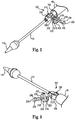
- FIG. 1 one embodiment of a stent delivery system 30 is shown in FIG. 1 .
- the system 30 generally includes a stability layer 32, an inner shaft assembly 34, a delivery sheath assembly 36, and a handle 38. Details on the various components are provided below.
- the delivery system 30 provides a loaded state in which a stent (not shown) is coupled to the inner shaft assembly 34 and compressively retained within a capsule 40 of the delivery sheath assembly 36.
- the delivery sheath assembly 36 can be manipulated to withdraw the capsule 40 proximally from the stent via operation of the handle 38, permitting the stent to self-expand and release from the inner shaft assembly 34.
- delivery systems in accordance with the present disclosure provide features capable of compressively retaining a self-deploying stent (e.g., the capsule 40) and a mechanism capable of effectuating release or deployment of the stent.
- a self-deploying stent e.g., the capsule 40
- the stability layer 32 illustratively includes a shaft 50, which forms a lumen 52 (referenced generally) sized to be slidably received over the inner shaft assembly 34, terminating at a distal end 54.
- the shaft 50 can take many forms and in general provides structural integrity to system 30, yet allowing sufficient flexibility to maneuver the capsule 40 to a target site (e.g., the aortic valve).
- target site e.g., the aortic valve
- shaft 50 in one embodiment, is formed of a polymeric material with an associated reinforcement layer. In other embodiments, the stability layer 32 can be eliminated.
- the inner shaft assembly 34 can have various constructions appropriate for supporting a stent within the capsule 40.
- the inner shaft assembly 34 can include a retention member 100, an intermediate tube 102, and a proximal tube 104.
- the retention member 100 can be akin to a plunger, and incorporates features for retaining the stent within the capsule 40 as described below.
- the tube 102 connects the retention member 100 to the proximal tube 104, with the proximal tube 104, in turn, coupling the inner shaft assembly 34 with the handle 38.
- the components 100-104 can combine to define a continuous lumen 106 (referenced generally) sized to slidably receive an auxiliary component such as a guide wire (not shown).
- the retention member 100 can include a tip 110, a support tube 112, and an attachment mechanism 120.
- the tip 110 forms or defines a nose cone having a distally tapering outer surface adapted to promote atraumatic contact with bodily tissue.
- the tip 110 can be fixed or slidable relative to the support tube 112.
- the support tube 112 extends proximally from the tip 110 and is configured to internally support a compressed stent generally disposed thereover, and has a length and outer diameter corresponding with dimensional attributes of the selected stent.
- the attachment mechanism 120 is attached to the support tube 112 opposite the tip 110 (e.g., with an adhesive bond), and is configured to selectively capture a corresponding feature of the stent.
- the attachment mechanism 120 can assume various forms, and is generally located along an intermediate portion of the inner shaft assembly 34.
- the attachment mechanism 120 includes one or more fingers sized to be received within corresponding apertures formed by the stent frame (e.g., the stent frame can form wire loops at an end thereof that are received over respective ones of the fingers when compressed within the capsule 40).
- the attachment mechanism 120 includes a pivot mechanism that effectuates release of the stent, as discussed in more detail below.
- the intermediate tube 102 is formed of a flexible polymer material (e.g., PEEK), and is sized to be slidably received within the delivery sheath assembly 36.
- the proximal tube 104 can include, in some embodiments, a leading portion 122 and a trailing portion 124.
- the leading portion 122 serves as a transition between the intermediate and proximal tubes 102, 104 and thus in some embodiments is a flexible polymer tubing (e.g., PEEK) having a diameter slightly less than that of the intermediate tube 102.
- the trailing portion 124 has a more rigid construction, configured for robust assembly with the handle 38 such as a metal hypotube, at a proximal end 126.
- Other constructions are also envisioned.
- the intermediate and proximal tubes 102, 104 are integrally formed as a single, homogenous tube or solid shaft.
- the delivery sheath assembly 36 includes the capsule 40 and a delivery sheath shaft 130, and defines proximal and distal ends 132, 134.
- the capsule 40 extends distally from the delivery shaft 130, and in some embodiments has a more stiffened construction (as compared to a stiffness of the delivery shaft 130) that exhibits sufficient radial or circumferential rigidity to overtly resist the expected expansive forces of the stent in the compressed arrangement.
- the delivery shaft 130 can be a polymer tube embedded with a metal braiding, whereas the capsule 40 is a laser-cut metal tube.
- the capsule 40 and the delivery shaft 130 can have a more uniform construction (e.g., a continuous polymer tube).
- the capsule 40 is constructed to compressively retain the stent at a predetermined diameter when loaded within the capsule 40, and the delivery shaft 130 serves to connect the capsule 40 with the handle 38.
- the delivery shaft 130 (as well as the capsule 40) is constructed to be sufficiently flexible for passage through a patient's vasculature, yet exhibit sufficient longitudinal rigidity to effectuate desired axial movement of the capsule 40.
- proximal retraction of the delivery shaft 130 is directly transferred to the capsule 40 and causes a corresponding proximal retraction of the capsule 40.
- the delivery shaft 130 is further configured to transmit a rotational force or movement onto the capsule 40.
- the handle 38 generally includes a housing 140 and one or more actuator mechanisms (i.e., controls) 142 (referenced generally).
- the housing 140 maintains the actuator mechanism(s) 142, with the handle 38 configured to facilitate sliding movement of the delivery sheath assembly 36 relative to the inner shaft assembly 34.
- the housing 140 can have any shape or size appropriate for convenient handling by a user.
- a first, deployment actuator mechanism 142a includes a user interface or actuator (e.g., a deployment actuator) 144 slidably retained by the housing 140 and coupled to a delivery sheath connector body 146.
- the proximal end 132 of the delivery sheath assembly 36 is connected to the delivery sheath connector body 146.
- the inner shaft assembly 34 and in particular the proximal tube 104, is slidably received within a passage 148 (referenced generally) of the delivery sheath connector body 146, and is rigidly coupled to the housing 140 at proximal end 126.
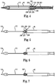
- FIGS. 2 and 3 illustrate exploded, isometric views of attachment mechanism 120, which includes a casing 200, pivoting lug 202 and an axle 204 for assisting in release of a stent from the delivery system 30.
- FIG. 4 is a sectional view of the coupling structure assembled within capsule 40.
- Casing 200 is directly coupled to tube 102 with a suitable fastening element 208 (e.g., exterior threads) positioned within tube 102, which may include internal threads for receiving fastening element 208.
- Casing 200 further defines a cavity 210 to accommodate pivoting lug 202 and opposed apertures 212 and 214 that receive axle 204.
- Lug 202 includes an elliptically shaped slot 216 positioned over support tube 112 and apertures 218 and 220 positioned on either side of slot 216. Furthermore, lug 202 includes fingers 222 and 224, to which a stent can be coupled during delivery. In one embodiment, the stent includes tabs or loops extending from a frame of the stent that are positioned in fingers 222 and 224. In particular, the fingers 222 and 224 are positioned on opposite sides of the lug 202 and define recessed portions to receive loops of the stent frame positioned therein. When compressively contained within capsule 40, the loops of the stent frame are coupled to the fingers 222 and 224.
- Axle 204 includes opposed ends 226 and 228 configured to form a press or interference fit with apertures 212 and 214 of casing 200, respectively. Additionally, upon assembly, axle 204 passes through apertures 218 and 220 of lug 202. Axle 204 also includes a central aperture 230 for support tube 112 to pass therethrough.
- FIGS. 5-7 illustrate the distal end of delivery system 30 with capsule 40 being retracted to expose the attachment mechanism 120. Due to the shape of slot 216 within lug 202, the lug 202 is allowed to pivot relative to the casing 200, for example to a first position 202' ( FIG. 6 ) or a second position 202" ( FIG. 7 ), in which the pivoting lug 202 comes into contact with support tube 112, preventing further rotation of the lug 202 relative to the casing. Forces placed on the lug 202 due to retraction of capsule 40 will cause the lug 202 to pivot about casing 200, effectuating release of a stent coupled thereto. As a result, situations where a stent gets caught on attachment mechanisms 202 can be prevented.
Applications Claiming Priority (2)
| Application Number | Priority Date | Filing Date | Title |
|---|---|---|---|
| US12/842,496 US8876878B2 (en) | 2010-07-23 | 2010-07-23 | Attachment mechanism for stent release |
| PCT/US2011/044883 WO2012012654A1 (en) | 2010-07-23 | 2011-07-21 | Attachment mechanism for stent release |
Publications (2)
| Publication Number | Publication Date |
|---|---|
| EP2595581A1 EP2595581A1 (en) | 2013-05-29 |
| EP2595581B1 true EP2595581B1 (en) | 2017-11-01 |
Family
ID=44629414
Family Applications (1)
| Application Number | Title | Priority Date | Filing Date |
|---|---|---|---|
| EP11738911.4A Active EP2595581B1 (en) | 2010-07-23 | 2011-07-21 | Attachment mechanism for stent release |
Country Status (7)
| Country | Link |
|---|---|
| US (3) | US8876878B2 (zh) |
| EP (1) | EP2595581B1 (zh) |
| JP (1) | JP6054293B2 (zh) |
| CN (1) | CN102985037B (zh) |
| AU (1) | AU2011281049B2 (zh) |
| BR (1) | BR112012033274A2 (zh) |
| WO (1) | WO2012012654A1 (zh) |
Families Citing this family (131)
| Publication number | Priority date | Publication date | Assignee | Title |
|---|---|---|---|---|
| WO2007047851A2 (en) | 2005-10-19 | 2007-04-26 | Pulsar Vascular, Inc. | Methods and systems for endovascularly clipping and repairing lumen and tissue defects |
| US9402707B2 (en) | 2008-07-22 | 2016-08-02 | Neuravi Limited | Clot capture systems and associated methods |
| KR101652804B1 (ko) | 2008-09-05 | 2016-08-31 | 펄사 배스큘라, 아이엔씨. | 생리적 구멍 또는 공동을 지지하거나 또는 폐쇄하기 위한 시스템과 방법 |
| US9192495B2 (en) | 2010-07-23 | 2015-11-24 | Medtronic, Inc. | Attachment mechanism for stent release |
| ES2683943T3 (es) | 2010-10-22 | 2018-09-28 | Neuravi Limited | Sistema de captura y extirpación de coágulos |
| US11259824B2 (en) | 2011-03-09 | 2022-03-01 | Neuravi Limited | Clot retrieval device for removing occlusive clot from a blood vessel |
| WO2012120490A2 (en) | 2011-03-09 | 2012-09-13 | Neuravi Limited | A clot retrieval device for removing occlusive clot from a blood vessel |
| EP2713904B1 (en) | 2011-06-03 | 2018-01-10 | Pulsar Vascular, Inc. | Aneurysm devices with additional anchoring mechanisms and associated systems |
| JP6174033B2 (ja) | 2011-10-05 | 2017-08-02 | パルサー バスキュラー インコーポレイテッド | 動脈瘤装置 |
| US9433521B2 (en) * | 2012-11-27 | 2016-09-06 | Medtronic, Inc. | Distal tip for a delivery catheter |
| US10561509B2 (en) | 2013-03-13 | 2020-02-18 | DePuy Synthes Products, Inc. | Braided stent with expansion ring and method of delivery |
| US10603157B2 (en) | 2013-03-13 | 2020-03-31 | DePuy Synthes Products, Inc. | Braid implant delivery and retraction device with distal engagement |
| PL2967611T3 (pl) | 2013-03-14 | 2019-08-30 | Neuravi Limited | Urządzenie do usuwania ostrych blokad z naczyń krwionośnych |
| CN105208950A (zh) | 2013-03-14 | 2015-12-30 | 尼尔拉维有限公司 | 一种用于从血管去除堵塞凝块的凝块收取装置 |
| US9433429B2 (en) | 2013-03-14 | 2016-09-06 | Neuravi Limited | Clot retrieval devices |
| US9414916B2 (en) * | 2013-07-17 | 2016-08-16 | Medtronic Vascular Galway | Adapter to actuate a delivery system |
| US10285720B2 (en) | 2014-03-11 | 2019-05-14 | Neuravi Limited | Clot retrieval system for removing occlusive clot from a blood vessel |
| US11154302B2 (en) | 2014-03-31 | 2021-10-26 | DePuy Synthes Products, Inc. | Aneurysm occlusion device |
| US11076860B2 (en) | 2014-03-31 | 2021-08-03 | DePuy Synthes Products, Inc. | Aneurysm occlusion device |
| WO2015189354A1 (en) | 2014-06-13 | 2015-12-17 | Neuravi Limited | Devices for removal of acute blockages from blood vessels |
| US10265086B2 (en) | 2014-06-30 | 2019-04-23 | Neuravi Limited | System for removing a clot from a blood vessel |
| US9918718B2 (en) | 2014-08-08 | 2018-03-20 | DePuy Synthes Products, Inc. | Embolic coil delivery system with retractable mechanical release mechanism |
| US10206796B2 (en) | 2014-08-27 | 2019-02-19 | DePuy Synthes Products, Inc. | Multi-strand implant with enhanced radiopacity |
| US9782178B2 (en) | 2014-09-19 | 2017-10-10 | DePuy Synthes Products, Inc. | Vasculature occlusion device detachment system with tapered corewire and heater activated fiber detachment |
| EP3223723B1 (en) | 2014-11-26 | 2020-01-08 | Neuravi Limited | A clot retrieval device for removing occlusive clot from a blood vessel |
| US10617435B2 (en) | 2014-11-26 | 2020-04-14 | Neuravi Limited | Clot retrieval device for removing clot from a blood vessel |
| US11253278B2 (en) | 2014-11-26 | 2022-02-22 | Neuravi Limited | Clot retrieval system for removing occlusive clot from a blood vessel |
| US10350067B2 (en) * | 2015-10-26 | 2019-07-16 | Edwards Lifesciences Corporation | Implant delivery capsule |
| US11116651B2 (en) | 2016-04-12 | 2021-09-14 | Suzhou Innomed Medical Device Co., Ltd | Vascular stent delivery system and tubing assembly thereof |
| CN107280830B (zh) * | 2016-04-12 | 2019-02-01 | 苏州茵络医疗器械有限公司 | 血管支架输送系统及其导管组件 |
| US10285710B2 (en) | 2016-06-01 | 2019-05-14 | DePuy Synthes Products, Inc. | Endovascular detachment system with flexible distal end and heater activated detachment |
| ES2834299T3 (es) | 2016-08-17 | 2021-06-17 | Neuravi Ltd | Un dispositivo de extracción de coágulos para eliminar un coágulo oclusivo de un vaso sanguíneo |
| US10076428B2 (en) | 2016-08-25 | 2018-09-18 | DePuy Synthes Products, Inc. | Expansion ring for a braided stent |
| MX2019002565A (es) | 2016-09-06 | 2019-09-18 | Neuravi Ltd | Dispositivo de extracción de coágulos para eliminar coágulos oclusivos de un vaso sanguíneo. |
| US10292851B2 (en) | 2016-09-30 | 2019-05-21 | DePuy Synthes Products, Inc. | Self-expanding device delivery apparatus with dual function bump |
| US10517708B2 (en) | 2016-10-26 | 2019-12-31 | DePuy Synthes Products, Inc. | Multi-basket clot capturing device |
| US10905853B2 (en) | 2017-01-17 | 2021-02-02 | DePuy Synthes Products, Inc. | System and method for delivering a catheter |
| US10881497B2 (en) | 2017-01-26 | 2021-01-05 | DePuy Synthes Products, Inc. | Composite vascular flow diverter |
| RU2019129526A (ru) | 2017-02-23 | 2021-03-23 | Депуи Синтез Продактс, Инк. | Устройство и система доставки для лечения аневризмы |
| US10806462B2 (en) | 2017-12-21 | 2020-10-20 | DePuy Synthes Products, Inc. | Implantable medical device detachment system with split tube and cylindrical coupling |
| US10751065B2 (en) | 2017-12-22 | 2020-08-25 | DePuy Synthes Products, Inc. | Aneurysm device and delivery system |
| US10905430B2 (en) | 2018-01-24 | 2021-02-02 | DePuy Synthes Products, Inc. | Aneurysm device and delivery system |
| US10918390B2 (en) | 2018-03-30 | 2021-02-16 | DePuy Synthes Products, Inc. | Helical balloon assist device and method for using the same |
| US10786259B2 (en) | 2018-03-30 | 2020-09-29 | DePuy Synthes Products, Inc. | Split balloon assist device and method for using the same |
| US10806461B2 (en) | 2018-04-27 | 2020-10-20 | DePuy Synthes Products, Inc. | Implantable medical device detachment system with split tube |
| CN108392298B (zh) * | 2018-05-11 | 2024-01-30 | 郑州大学第一附属医院 | 一种可控倒y型气道支架输送装置 |
| US11596412B2 (en) | 2018-05-25 | 2023-03-07 | DePuy Synthes Products, Inc. | Aneurysm device and delivery system |
| US11058430B2 (en) | 2018-05-25 | 2021-07-13 | DePuy Synthes Products, Inc. | Aneurysm device and delivery system |
| US10939915B2 (en) | 2018-05-31 | 2021-03-09 | DePuy Synthes Products, Inc. | Aneurysm device and delivery system |
| US10667833B2 (en) | 2018-06-08 | 2020-06-02 | Neuravi Limited | Guidewire with an atraumatic clot-circumventing configured distal end for use in an endovascular medical system |
| US10898216B2 (en) | 2018-06-13 | 2021-01-26 | DePuy Synthes Products, Inc. | Vasculature obstruction capture device |
| AU2019204522A1 (en) | 2018-07-30 | 2020-02-13 | DePuy Synthes Products, Inc. | Systems and methods of manufacturing and using an expansion ring |
| US10905431B2 (en) | 2018-08-03 | 2021-02-02 | DePuy Synthes Products, Inc. | Spiral delivery system for embolic braid |
| US10456280B1 (en) | 2018-08-06 | 2019-10-29 | DePuy Synthes Products, Inc. | Systems and methods of using a braided implant |
| US10278848B1 (en) | 2018-08-06 | 2019-05-07 | DePuy Synthes Products, Inc. | Stent delivery with expansion assisting delivery wire |
| US11051825B2 (en) | 2018-08-08 | 2021-07-06 | DePuy Synthes Products, Inc. | Delivery system for embolic braid |
| US10813780B2 (en) | 2018-08-08 | 2020-10-27 | DePuy Synthes Products, Inc. | Intraluminal implant delivery system and method |
| US10842498B2 (en) | 2018-09-13 | 2020-11-24 | Neuravi Limited | Systems and methods of restoring perfusion to a vessel |
| KR20200033757A (ko) | 2018-09-20 | 2020-03-30 | 디퍼이 신테스 프로덕츠, 인코포레이티드 | 형상화된 와이어를 갖는 스텐트 |
| US11123077B2 (en) | 2018-09-25 | 2021-09-21 | DePuy Synthes Products, Inc. | Intrasaccular device positioning and deployment system |
| US11406416B2 (en) | 2018-10-02 | 2022-08-09 | Neuravi Limited | Joint assembly for vasculature obstruction capture device |
| US11253287B2 (en) | 2018-10-04 | 2022-02-22 | Neuravi Limited | Retrograde blood flow occlusion flushing device |
| US11076861B2 (en) | 2018-10-12 | 2021-08-03 | DePuy Synthes Products, Inc. | Folded aneurysm treatment device and delivery method |
| US11406392B2 (en) | 2018-12-12 | 2022-08-09 | DePuy Synthes Products, Inc. | Aneurysm occluding device for use with coagulating agents |
| US11147562B2 (en) | 2018-12-12 | 2021-10-19 | DePuy Synthes Products, Inc. | Systems and methods for embolic implant detachment |
| US11272939B2 (en) | 2018-12-18 | 2022-03-15 | DePuy Synthes Products, Inc. | Intrasaccular flow diverter for treating cerebral aneurysms |
| US11039944B2 (en) | 2018-12-27 | 2021-06-22 | DePuy Synthes Products, Inc. | Braided stent system with one or more expansion rings |
| US11134953B2 (en) | 2019-02-06 | 2021-10-05 | DePuy Synthes Products, Inc. | Adhesive cover occluding device for aneurysm treatment |
| US11273285B2 (en) | 2019-02-07 | 2022-03-15 | DePuy Synthes Products, Inc. | Ancillary device for detaching implants |
| EP3705066B1 (en) | 2019-03-04 | 2021-12-29 | Neuravi Limited | Actuated clot retrieval catheter |
| US11382633B2 (en) | 2019-03-06 | 2022-07-12 | DePuy Synthes Products, Inc. | Strut flow diverter for cerebral aneurysms and methods for preventing strut entanglement |
| US11337706B2 (en) | 2019-03-27 | 2022-05-24 | DePuy Synthes Products, Inc. | Aneurysm treatment device |
| US11185334B2 (en) | 2019-03-28 | 2021-11-30 | DePuy Synthes Products, Inc. | Single lumen reduced profile occlusion balloon catheter |
| US11051928B2 (en) | 2019-04-11 | 2021-07-06 | Neuravi Limited | Floating carotid filter |
| US11931522B2 (en) | 2019-05-09 | 2024-03-19 | Neuravi Limited | Inflation lumen kink protection and balloon profile |
| US11607531B2 (en) | 2019-05-09 | 2023-03-21 | Neuravi Limited | Balloon catheter with venting of residual air in a proximal direction |
| US11957855B2 (en) | 2019-05-09 | 2024-04-16 | Neuravi Limited | Balloon guide catheter with positive venting of residual air |
| US11571553B2 (en) | 2019-05-09 | 2023-02-07 | Neuravi Limited | Balloon guide catheter with thermally expandable material |
| USD959659S1 (en) | 2019-05-10 | 2022-08-02 | DePuy Synthes Products, Inc. | Implant release handle |
| US11278292B2 (en) | 2019-05-21 | 2022-03-22 | DePuy Synthes Products, Inc. | Inverting braided aneurysm treatment system and method |
| US10653425B1 (en) | 2019-05-21 | 2020-05-19 | DePuy Synthes Products, Inc. | Layered braided aneurysm treatment device |
| US11497504B2 (en) | 2019-05-21 | 2022-11-15 | DePuy Synthes Products, Inc. | Aneurysm treatment with pushable implanted braid |
| US11413046B2 (en) | 2019-05-21 | 2022-08-16 | DePuy Synthes Products, Inc. | Layered braided aneurysm treatment device |
| US11602350B2 (en) | 2019-12-05 | 2023-03-14 | DePuy Synthes Products, Inc. | Intrasaccular inverting braid with highly flexible fill material |
| US11607226B2 (en) | 2019-05-21 | 2023-03-21 | DePuy Synthes Products, Inc. | Layered braided aneurysm treatment device with corrugations |
| US11672542B2 (en) | 2019-05-21 | 2023-06-13 | DePuy Synthes Products, Inc. | Aneurysm treatment with pushable ball segment |
| US11109939B2 (en) | 2019-06-14 | 2021-09-07 | DePuy Synthes Products, Inc. | Intravascular devices with radiopaque body markers |
| US11406403B2 (en) | 2019-06-14 | 2022-08-09 | Neuravi Limited | Visibility of mechanical thrombectomy device during diagnostic imaging |
| US11253265B2 (en) | 2019-06-18 | 2022-02-22 | DePuy Synthes Products, Inc. | Pull wire detachment for intravascular devices |
| US11207494B2 (en) | 2019-07-03 | 2021-12-28 | DePuy Synthes Products, Inc. | Medical device delivery member with flexible stretch resistant distal portion |
| US11426174B2 (en) | 2019-10-03 | 2022-08-30 | DePuy Synthes Products, Inc. | Medical device delivery member with flexible stretch resistant mechanical release |
| US11266426B2 (en) | 2019-07-10 | 2022-03-08 | DePuy Synthes Products, Inc. | Streamlined treatment of clot removal, angioplasty and prevention of restenosis using a single integrated intravascular device |
| US11266427B2 (en) | 2019-07-10 | 2022-03-08 | Neuravi Limited | Self-expanding intravascular medical device |
| US11395675B2 (en) | 2019-07-11 | 2022-07-26 | DePuy Synthes Products, Inc. | Clot retriever cleaning for reinsertion |
| JP2021041169A (ja) | 2019-09-11 | 2021-03-18 | ニューラヴィ・リミテッド | 拡大可能な口腔カテーテル |
| US11439403B2 (en) | 2019-09-17 | 2022-09-13 | DePuy Synthes Products, Inc. | Embolic coil proximal connecting element and stretch resistant fiber |
| US11712231B2 (en) | 2019-10-29 | 2023-08-01 | Neuravi Limited | Proximal locking assembly design for dual stent mechanical thrombectomy device |
| US11376013B2 (en) | 2019-11-18 | 2022-07-05 | DePuy Synthes Products, Inc. | Implant delivery system with braid cup formation |
| US11628282B2 (en) | 2019-11-25 | 2023-04-18 | Neuravi Limited | No preparation balloon guide catheter |
| US11779364B2 (en) | 2019-11-27 | 2023-10-10 | Neuravi Limited | Actuated expandable mouth thrombectomy catheter |
| US11839725B2 (en) | 2019-11-27 | 2023-12-12 | Neuravi Limited | Clot retrieval device with outer sheath and inner catheter |
| US11517340B2 (en) | 2019-12-03 | 2022-12-06 | Neuravi Limited | Stentriever devices for removing an occlusive clot from a vessel and methods thereof |
| US11457926B2 (en) | 2019-12-18 | 2022-10-04 | DePuy Synthes Products, Inc. | Implant having an intrasaccular section and intravascular section |
| US11457922B2 (en) | 2020-01-22 | 2022-10-04 | DePuy Synthes Products, Inc. | Medical device delivery member with flexible stretch resistant distal portion |
| US11957354B2 (en) | 2020-02-10 | 2024-04-16 | DePuy Synthes Products, Inc. | Aneurysm implant support device |
| US11432822B2 (en) | 2020-02-14 | 2022-09-06 | DePuy Synthes Products, Inc. | Intravascular implant deployment system |
| US11633198B2 (en) | 2020-03-05 | 2023-04-25 | Neuravi Limited | Catheter proximal joint |
| US11944327B2 (en) | 2020-03-05 | 2024-04-02 | Neuravi Limited | Expandable mouth aspirating clot retrieval catheter |
| US11883043B2 (en) | 2020-03-31 | 2024-01-30 | DePuy Synthes Products, Inc. | Catheter funnel extension |
| US11759217B2 (en) | 2020-04-07 | 2023-09-19 | Neuravi Limited | Catheter tubular support |
| US11730501B2 (en) | 2020-04-17 | 2023-08-22 | Neuravi Limited | Floating clot retrieval device for removing clots from a blood vessel |
| US11871946B2 (en) | 2020-04-17 | 2024-01-16 | Neuravi Limited | Clot retrieval device for removing clot from a blood vessel |
| US11717308B2 (en) | 2020-04-17 | 2023-08-08 | Neuravi Limited | Clot retrieval device for removing heterogeneous clots from a blood vessel |
| US11523831B2 (en) | 2020-04-30 | 2022-12-13 | DePuy Synthes Products, Inc. | Intrasaccular flow diverter |
| US11737771B2 (en) | 2020-06-18 | 2023-08-29 | Neuravi Limited | Dual channel thrombectomy device |
| US11937836B2 (en) | 2020-06-22 | 2024-03-26 | Neuravi Limited | Clot retrieval system with expandable clot engaging framework |
| US11395669B2 (en) | 2020-06-23 | 2022-07-26 | Neuravi Limited | Clot retrieval device with flexible collapsible frame |
| US11439418B2 (en) | 2020-06-23 | 2022-09-13 | Neuravi Limited | Clot retrieval device for removing clot from a blood vessel |
| US11951026B2 (en) | 2020-06-30 | 2024-04-09 | DePuy Synthes Products, Inc. | Implantable medical device detachment system with flexible braid section |
| US11864781B2 (en) | 2020-09-23 | 2024-01-09 | Neuravi Limited | Rotating frame thrombectomy device |
| US11826520B2 (en) | 2020-12-08 | 2023-11-28 | DePuy Synthes Products, Inc. | Catheter designs for enhanced column strength |
| US11786698B2 (en) | 2020-12-08 | 2023-10-17 | DePuy Synthes Products, Inc. | Catheter with textured surface |
| US11937837B2 (en) | 2020-12-29 | 2024-03-26 | Neuravi Limited | Fibrin rich / soft clot mechanical thrombectomy device |
| US11872354B2 (en) | 2021-02-24 | 2024-01-16 | Neuravi Limited | Flexible catheter shaft frame with seam |
| US11974764B2 (en) | 2021-06-04 | 2024-05-07 | Neuravi Limited | Self-orienting rotating stentriever pinching cells |
| US11937839B2 (en) | 2021-09-28 | 2024-03-26 | Neuravi Limited | Catheter with electrically actuated expandable mouth |
| US11751881B2 (en) | 2021-11-26 | 2023-09-12 | DePuy Synthes Products, Inc. | Securement wire withstanding forces during deployment of implantable intravascular treatment device using a delivery and detachment system |
| US11937824B2 (en) | 2021-12-30 | 2024-03-26 | DePuy Synthes Products, Inc. | Implant detachment systems with a modified pull wire |
| US11844490B2 (en) | 2021-12-30 | 2023-12-19 | DePuy Synthes Products, Inc. | Suture linkage for inhibiting premature embolic implant deployment |
| US11937825B2 (en) | 2022-03-02 | 2024-03-26 | DePuy Synthes Products, Inc. | Hook wire for preventing premature embolic implant detachment |
| US11937826B2 (en) | 2022-03-14 | 2024-03-26 | DePuy Synthes Products, Inc. | Proximal link wire for preventing premature implant detachment |
Family Cites Families (14)
| Publication number | Priority date | Publication date | Assignee | Title |
|---|---|---|---|---|
| CA2134090C (en) | 1992-05-08 | 1997-03-25 | Liann M. Johnson | Esophageal stent and delivery tool |
| US5817102A (en) | 1992-05-08 | 1998-10-06 | Schneider (Usa) Inc. | Apparatus for delivering and deploying a stent |
| DE69419877T2 (de) | 1993-11-04 | 1999-12-16 | Bard Inc C R | Ortsfeste Gefässprothese |
| US5417708A (en) | 1994-03-09 | 1995-05-23 | Cook Incorporated | Intravascular treatment system and percutaneous release mechanism therefor |
| US5601600A (en) | 1995-09-08 | 1997-02-11 | Conceptus, Inc. | Endoluminal coil delivery system having a mechanical release mechanism |
| US6168616B1 (en) * | 1997-06-02 | 2001-01-02 | Global Vascular Concepts | Manually expandable stent |
| US6530952B2 (en) * | 1997-12-29 | 2003-03-11 | The Cleveland Clinic Foundation | Bioprosthetic cardiovascular valve system |
| US6214036B1 (en) | 1998-11-09 | 2001-04-10 | Cordis Corporation | Stent which is easily recaptured and repositioned within the body |
| US6582451B1 (en) | 1999-03-16 | 2003-06-24 | The University Of Sydney | Device for use in surgery |
| US6858034B1 (en) * | 1999-05-20 | 2005-02-22 | Scimed Life Systems, Inc. | Stent delivery system for prevention of kinking, and method of loading and using same |
| US7556646B2 (en) * | 2001-09-13 | 2009-07-07 | Edwards Lifesciences Corporation | Methods and apparatuses for deploying minimally-invasive heart valves |
| US6673106B2 (en) | 2001-06-14 | 2004-01-06 | Cordis Neurovascular, Inc. | Intravascular stent device |
| US7763062B2 (en) * | 2003-01-21 | 2010-07-27 | Boston Scientific Scimed, Inc. | Method and system for delivering and implanting a graft |
| US8652202B2 (en) | 2008-08-22 | 2014-02-18 | Edwards Lifesciences Corporation | Prosthetic heart valve and delivery apparatus |
-
2010
- 2010-07-23 US US12/842,496 patent/US8876878B2/en active Active
-
2011
- 2011-07-21 CN CN201180034061.4A patent/CN102985037B/zh active Active
- 2011-07-21 AU AU2011281049A patent/AU2011281049B2/en not_active Ceased
- 2011-07-21 WO PCT/US2011/044883 patent/WO2012012654A1/en active Application Filing
- 2011-07-21 BR BR112012033274A patent/BR112012033274A2/pt not_active Application Discontinuation
- 2011-07-21 JP JP2013521837A patent/JP6054293B2/ja active Active
- 2011-07-21 EP EP11738911.4A patent/EP2595581B1/en active Active
-
2014
- 2014-10-01 US US14/503,522 patent/US9662238B2/en active Active
-
2017
- 2017-04-28 US US15/581,005 patent/US20170224511A1/en not_active Abandoned
Non-Patent Citations (1)
| Title |
|---|
| None * |
Also Published As
| Publication number | Publication date |
|---|---|
| US8876878B2 (en) | 2014-11-04 |
| JP2013535275A (ja) | 2013-09-12 |
| JP6054293B2 (ja) | 2016-12-27 |
| BR112012033274A2 (pt) | 2016-11-22 |
| US20150018930A1 (en) | 2015-01-15 |
| EP2595581A1 (en) | 2013-05-29 |
| CN102985037B (zh) | 2016-08-24 |
| WO2012012654A1 (en) | 2012-01-26 |
| CN102985037A (zh) | 2013-03-20 |
| US9662238B2 (en) | 2017-05-30 |
| US20170224511A1 (en) | 2017-08-10 |
| AU2011281049B2 (en) | 2014-06-05 |
| AU2011281049A1 (en) | 2013-01-17 |
| US20120022628A1 (en) | 2012-01-26 |
Similar Documents
| Publication | Publication Date | Title |
|---|---|---|
| EP2595581B1 (en) | Attachment mechanism for stent release | |
| EP2925259B1 (en) | Prosthetic valve crimping | |
| US8133266B2 (en) | Expandable tip delivery system and method | |
| EP1923020B1 (en) | Stent-graft with anchoring pins | |
| EP2552355B1 (en) | Transcatheter prosthetic heart valve delivery system with recapturing feature | |
| CN111971000A (zh) | 具有末端行程限制件的假体递送系统及其使用方法 | |
| EP2558039B1 (en) | Delivery system ejection component and method | |
| EP2558040B1 (en) | Delivery system ejection component | |
| EP2282704B1 (en) | Introducer | |
| EP1982677A2 (en) | Delivery system for stent-graft | |
| US20080228255A1 (en) | Positionable Stent-Graft Delivery System and Method | |
| US9192495B2 (en) | Attachment mechanism for stent release | |
| EP2586405B1 (en) | Releasable top cap assembly | |
| EP3245986B1 (en) | Wire retention and release mechanisms | |
| US20220273474A1 (en) | Structure for a catheter sleeve or an implant | |
| US20210282952A1 (en) | Endovascular catheter with delivery system separately assembled to stent graft system |
Legal Events
| Date | Code | Title | Description |
|---|---|---|---|
| PUAI | Public reference made under article 153(3) epc to a published international application that has entered the european phase |
Free format text: ORIGINAL CODE: 0009012 |
|
| 17P | Request for examination filed |
Effective date: 20130213 |
|
| AK | Designated contracting states |
Kind code of ref document: A1 Designated state(s): AL AT BE BG CH CY CZ DE DK EE ES FI FR GB GR HR HU IE IS IT LI LT LU LV MC MK MT NL NO PL PT RO RS SE SI SK SM TR |
|
| DAX | Request for extension of the european patent (deleted) | ||
| REG | Reference to a national code |
Ref country code: DE Ref legal event code: R079 Ref document number: 602011042907 Country of ref document: DE Free format text: PREVIOUS MAIN CLASS: A61F0002840000 Ipc: A61F0002950000 |
|
| GRAP | Despatch of communication of intention to grant a patent |
Free format text: ORIGINAL CODE: EPIDOSNIGR1 |
|
| RIC1 | Information provided on ipc code assigned before grant |
Ipc: A61F 2/95 20130101AFI20170614BHEP |
|
| INTG | Intention to grant announced |
Effective date: 20170719 |
|
| GRAS | Grant fee paid |
Free format text: ORIGINAL CODE: EPIDOSNIGR3 |
|
| GRAA | (expected) grant |
Free format text: ORIGINAL CODE: 0009210 |
|
| AK | Designated contracting states |
Kind code of ref document: B1 Designated state(s): AL AT BE BG CH CY CZ DE DK EE ES FI FR GB GR HR HU IE IS IT LI LT LU LV MC MK MT NL NO PL PT RO RS SE SI SK SM TR |
|
| REG | Reference to a national code |
Ref country code: GB Ref legal event code: FG4D |
|
| REG | Reference to a national code |
Ref country code: CH Ref legal event code: EP Ref country code: AT Ref legal event code: REF Ref document number: 941258 Country of ref document: AT Kind code of ref document: T Effective date: 20171115 |
|
| REG | Reference to a national code |
Ref country code: IE Ref legal event code: FG4D |
|
| REG | Reference to a national code |
Ref country code: NL Ref legal event code: FP |
|
| REG | Reference to a national code |
Ref country code: DE Ref legal event code: R096 Ref document number: 602011042907 Country of ref document: DE |
|
| REG | Reference to a national code |
Ref country code: CH Ref legal event code: NV Representative=s name: RENTSCH PARTNER AG, CH |
|
| REG | Reference to a national code |
Ref country code: LT Ref legal event code: MG4D |
|
| REG | Reference to a national code |
Ref country code: AT Ref legal event code: MK05 Ref document number: 941258 Country of ref document: AT Kind code of ref document: T Effective date: 20171101 |
|
| PG25 | Lapsed in a contracting state [announced via postgrant information from national office to epo] |
Ref country code: LT Free format text: LAPSE BECAUSE OF FAILURE TO SUBMIT A TRANSLATION OF THE DESCRIPTION OR TO PAY THE FEE WITHIN THE PRESCRIBED TIME-LIMIT Effective date: 20171101 Ref country code: SE Free format text: LAPSE BECAUSE OF FAILURE TO SUBMIT A TRANSLATION OF THE DESCRIPTION OR TO PAY THE FEE WITHIN THE PRESCRIBED TIME-LIMIT Effective date: 20171101 Ref country code: FI Free format text: LAPSE BECAUSE OF FAILURE TO SUBMIT A TRANSLATION OF THE DESCRIPTION OR TO PAY THE FEE WITHIN THE PRESCRIBED TIME-LIMIT Effective date: 20171101 Ref country code: NO Free format text: LAPSE BECAUSE OF FAILURE TO SUBMIT A TRANSLATION OF THE DESCRIPTION OR TO PAY THE FEE WITHIN THE PRESCRIBED TIME-LIMIT Effective date: 20180201 Ref country code: ES Free format text: LAPSE BECAUSE OF FAILURE TO SUBMIT A TRANSLATION OF THE DESCRIPTION OR TO PAY THE FEE WITHIN THE PRESCRIBED TIME-LIMIT Effective date: 20171101 |
|
| PG25 | Lapsed in a contracting state [announced via postgrant information from national office to epo] |
Ref country code: IS Free format text: LAPSE BECAUSE OF FAILURE TO SUBMIT A TRANSLATION OF THE DESCRIPTION OR TO PAY THE FEE WITHIN THE PRESCRIBED TIME-LIMIT Effective date: 20180301 Ref country code: GR Free format text: LAPSE BECAUSE OF FAILURE TO SUBMIT A TRANSLATION OF THE DESCRIPTION OR TO PAY THE FEE WITHIN THE PRESCRIBED TIME-LIMIT Effective date: 20180202 Ref country code: HR Free format text: LAPSE BECAUSE OF FAILURE TO SUBMIT A TRANSLATION OF THE DESCRIPTION OR TO PAY THE FEE WITHIN THE PRESCRIBED TIME-LIMIT Effective date: 20171101 Ref country code: BG Free format text: LAPSE BECAUSE OF FAILURE TO SUBMIT A TRANSLATION OF THE DESCRIPTION OR TO PAY THE FEE WITHIN THE PRESCRIBED TIME-LIMIT Effective date: 20180201 Ref country code: RS Free format text: LAPSE BECAUSE OF FAILURE TO SUBMIT A TRANSLATION OF THE DESCRIPTION OR TO PAY THE FEE WITHIN THE PRESCRIBED TIME-LIMIT Effective date: 20171101 Ref country code: LV Free format text: LAPSE BECAUSE OF FAILURE TO SUBMIT A TRANSLATION OF THE DESCRIPTION OR TO PAY THE FEE WITHIN THE PRESCRIBED TIME-LIMIT Effective date: 20171101 Ref country code: AT Free format text: LAPSE BECAUSE OF FAILURE TO SUBMIT A TRANSLATION OF THE DESCRIPTION OR TO PAY THE FEE WITHIN THE PRESCRIBED TIME-LIMIT Effective date: 20171101 |
|
| REG | Reference to a national code |
Ref country code: FR Ref legal event code: PLFP Year of fee payment: 8 |
|
| PG25 | Lapsed in a contracting state [announced via postgrant information from national office to epo] |
Ref country code: CZ Free format text: LAPSE BECAUSE OF FAILURE TO SUBMIT A TRANSLATION OF THE DESCRIPTION OR TO PAY THE FEE WITHIN THE PRESCRIBED TIME-LIMIT Effective date: 20171101 Ref country code: SK Free format text: LAPSE BECAUSE OF FAILURE TO SUBMIT A TRANSLATION OF THE DESCRIPTION OR TO PAY THE FEE WITHIN THE PRESCRIBED TIME-LIMIT Effective date: 20171101 Ref country code: CY Free format text: LAPSE BECAUSE OF FAILURE TO SUBMIT A TRANSLATION OF THE DESCRIPTION OR TO PAY THE FEE WITHIN THE PRESCRIBED TIME-LIMIT Effective date: 20171101 Ref country code: DK Free format text: LAPSE BECAUSE OF FAILURE TO SUBMIT A TRANSLATION OF THE DESCRIPTION OR TO PAY THE FEE WITHIN THE PRESCRIBED TIME-LIMIT Effective date: 20171101 Ref country code: EE Free format text: LAPSE BECAUSE OF FAILURE TO SUBMIT A TRANSLATION OF THE DESCRIPTION OR TO PAY THE FEE WITHIN THE PRESCRIBED TIME-LIMIT Effective date: 20171101 |
|
| REG | Reference to a national code |
Ref country code: DE Ref legal event code: R097 Ref document number: 602011042907 Country of ref document: DE |
|
| PG25 | Lapsed in a contracting state [announced via postgrant information from national office to epo] |
Ref country code: IT Free format text: LAPSE BECAUSE OF FAILURE TO SUBMIT A TRANSLATION OF THE DESCRIPTION OR TO PAY THE FEE WITHIN THE PRESCRIBED TIME-LIMIT Effective date: 20171101 Ref country code: RO Free format text: LAPSE BECAUSE OF FAILURE TO SUBMIT A TRANSLATION OF THE DESCRIPTION OR TO PAY THE FEE WITHIN THE PRESCRIBED TIME-LIMIT Effective date: 20171101 Ref country code: PL Free format text: LAPSE BECAUSE OF FAILURE TO SUBMIT A TRANSLATION OF THE DESCRIPTION OR TO PAY THE FEE WITHIN THE PRESCRIBED TIME-LIMIT Effective date: 20171101 Ref country code: SM Free format text: LAPSE BECAUSE OF FAILURE TO SUBMIT A TRANSLATION OF THE DESCRIPTION OR TO PAY THE FEE WITHIN THE PRESCRIBED TIME-LIMIT Effective date: 20171101 |
|
| PLBE | No opposition filed within time limit |
Free format text: ORIGINAL CODE: 0009261 |
|
| STAA | Information on the status of an ep patent application or granted ep patent |
Free format text: STATUS: NO OPPOSITION FILED WITHIN TIME LIMIT |
|
| 26N | No opposition filed |
Effective date: 20180802 |
|
| PG25 | Lapsed in a contracting state [announced via postgrant information from national office to epo] |
Ref country code: SI Free format text: LAPSE BECAUSE OF FAILURE TO SUBMIT A TRANSLATION OF THE DESCRIPTION OR TO PAY THE FEE WITHIN THE PRESCRIBED TIME-LIMIT Effective date: 20171101 |
|
| GBPC | Gb: european patent ceased through non-payment of renewal fee |
Effective date: 20180721 |
|
| PG25 | Lapsed in a contracting state [announced via postgrant information from national office to epo] |
Ref country code: LU Free format text: LAPSE BECAUSE OF NON-PAYMENT OF DUE FEES Effective date: 20180721 Ref country code: MC Free format text: LAPSE BECAUSE OF FAILURE TO SUBMIT A TRANSLATION OF THE DESCRIPTION OR TO PAY THE FEE WITHIN THE PRESCRIBED TIME-LIMIT Effective date: 20171101 |
|
| REG | Reference to a national code |
Ref country code: BE Ref legal event code: MM Effective date: 20180731 |
|
| PG25 | Lapsed in a contracting state [announced via postgrant information from national office to epo] |
Ref country code: GB Free format text: LAPSE BECAUSE OF NON-PAYMENT OF DUE FEES Effective date: 20180721 |
|
| PG25 | Lapsed in a contracting state [announced via postgrant information from national office to epo] |
Ref country code: BE Free format text: LAPSE BECAUSE OF NON-PAYMENT OF DUE FEES Effective date: 20180731 |
|
| PGFP | Annual fee paid to national office [announced via postgrant information from national office to epo] |
Ref country code: GB Payment date: 20190627 Year of fee payment: 13 |
|
| PGFP | Annual fee paid to national office [announced via postgrant information from national office to epo] |
Ref country code: CH Payment date: 20190624 Year of fee payment: 9 |
|
| PG25 | Lapsed in a contracting state [announced via postgrant information from national office to epo] |
Ref country code: MT Free format text: LAPSE BECAUSE OF NON-PAYMENT OF DUE FEES Effective date: 20180721 |
|
| PG25 | Lapsed in a contracting state [announced via postgrant information from national office to epo] |
Ref country code: TR Free format text: LAPSE BECAUSE OF FAILURE TO SUBMIT A TRANSLATION OF THE DESCRIPTION OR TO PAY THE FEE WITHIN THE PRESCRIBED TIME-LIMIT Effective date: 20171101 |
|
| PG25 | Lapsed in a contracting state [announced via postgrant information from national office to epo] |
Ref country code: HU Free format text: LAPSE BECAUSE OF FAILURE TO SUBMIT A TRANSLATION OF THE DESCRIPTION OR TO PAY THE FEE WITHIN THE PRESCRIBED TIME-LIMIT; INVALID AB INITIO Effective date: 20110721 Ref country code: PT Free format text: LAPSE BECAUSE OF FAILURE TO SUBMIT A TRANSLATION OF THE DESCRIPTION OR TO PAY THE FEE WITHIN THE PRESCRIBED TIME-LIMIT Effective date: 20171101 |
|
| PG25 | Lapsed in a contracting state [announced via postgrant information from national office to epo] |
Ref country code: MK Free format text: LAPSE BECAUSE OF NON-PAYMENT OF DUE FEES Effective date: 20171101 |
|
| PG25 | Lapsed in a contracting state [announced via postgrant information from national office to epo] |
Ref country code: AL Free format text: LAPSE BECAUSE OF FAILURE TO SUBMIT A TRANSLATION OF THE DESCRIPTION OR TO PAY THE FEE WITHIN THE PRESCRIBED TIME-LIMIT Effective date: 20171101 |
|
| REG | Reference to a national code |
Ref country code: CH Ref legal event code: PL |
|
| REG | Reference to a national code |
Ref country code: NL Ref legal event code: MM Effective date: 20200801 |
|
| PG25 | Lapsed in a contracting state [announced via postgrant information from national office to epo] |
Ref country code: LI Free format text: LAPSE BECAUSE OF NON-PAYMENT OF DUE FEES Effective date: 20200731 Ref country code: CH Free format text: LAPSE BECAUSE OF NON-PAYMENT OF DUE FEES Effective date: 20200731 Ref country code: NL Free format text: LAPSE BECAUSE OF NON-PAYMENT OF DUE FEES Effective date: 20200801 |
|
| PGFP | Annual fee paid to national office [announced via postgrant information from national office to epo] |
Ref country code: IE Payment date: 20230622 Year of fee payment: 13 |
|
| PGFP | Annual fee paid to national office [announced via postgrant information from national office to epo] |
Ref country code: FR Payment date: 20230724 Year of fee payment: 13 Ref country code: DE Payment date: 20230620 Year of fee payment: 13 |