EP2594522A2 - Vorrichtung, Verfahren und Computerprogrammprodukt zum Bewegen von Fracht, und Satz und Verfahren zur Verbesserung einer Vorrichtung zum Bewegen von Fracht - Google Patents
Vorrichtung, Verfahren und Computerprogrammprodukt zum Bewegen von Fracht, und Satz und Verfahren zur Verbesserung einer Vorrichtung zum Bewegen von Fracht Download PDFInfo
- Publication number
- EP2594522A2 EP2594522A2 EP12192204.1A EP12192204A EP2594522A2 EP 2594522 A2 EP2594522 A2 EP 2594522A2 EP 12192204 A EP12192204 A EP 12192204A EP 2594522 A2 EP2594522 A2 EP 2594522A2
- Authority
- EP
- European Patent Office
- Prior art keywords
- bus
- hydraulic accumulator
- energy
- electrical energy
- hydraulic
- Prior art date
- Legal status (The legal status is an assumption and is not a legal conclusion. Google has not performed a legal analysis and makes no representation as to the accuracy of the status listed.)
- Granted
Links
Images


Classifications
-
- F—MECHANICAL ENGINEERING; LIGHTING; HEATING; WEAPONS; BLASTING
- F15—FLUID-PRESSURE ACTUATORS; HYDRAULICS OR PNEUMATICS IN GENERAL
- F15B—SYSTEMS ACTING BY MEANS OF FLUIDS IN GENERAL; FLUID-PRESSURE ACTUATORS, e.g. SERVOMOTORS; DETAILS OF FLUID-PRESSURE SYSTEMS, NOT OTHERWISE PROVIDED FOR
- F15B15/00—Fluid-actuated devices for displacing a member from one position to another; Gearing associated therewith
-
- H—ELECTRICITY
- H02—GENERATION; CONVERSION OR DISTRIBUTION OF ELECTRIC POWER
- H02J—ELECTRIC POWER NETWORKS; CIRCUIT ARRANGEMENTS OR SYSTEMS FOR SUPPLYING OR DISTRIBUTING ELECTRIC POWER; SYSTEMS FOR STORING ELECTRIC ENERGY
- H02J15/00—Systems for storing electric energy specially adapted for power networks
- H02J15/10—Systems for storing electric energy specially adapted for power networks using storage of hydraulic energy
-
- B—PERFORMING OPERATIONS; TRANSPORTING
- B66—HOISTING; LIFTING; HAULING
- B66C—CRANES; LOAD-ENGAGING ELEMENTS OR DEVICES FOR CRANES, CAPSTANS, WINCHES, OR TACKLES
- B66C13/00—Other constructional features or details
- B66C13/18—Control systems or devices
-
- F—MECHANICAL ENGINEERING; LIGHTING; HEATING; WEAPONS; BLASTING
- F15—FLUID-PRESSURE ACTUATORS; HYDRAULICS OR PNEUMATICS IN GENERAL
- F15B—SYSTEMS ACTING BY MEANS OF FLUIDS IN GENERAL; FLUID-PRESSURE ACTUATORS, e.g. SERVOMOTORS; DETAILS OF FLUID-PRESSURE SYSTEMS, NOT OTHERWISE PROVIDED FOR
- F15B1/00—Installations or systems with accumulators; Supply reservoir or sump assemblies
- F15B1/02—Installations or systems with accumulators
- F15B1/024—Installations or systems with accumulators used as a supplementary power source, e.g. to store energy in idle periods to balance pump load
-
- F—MECHANICAL ENGINEERING; LIGHTING; HEATING; WEAPONS; BLASTING
- F15—FLUID-PRESSURE ACTUATORS; HYDRAULICS OR PNEUMATICS IN GENERAL
- F15B—SYSTEMS ACTING BY MEANS OF FLUIDS IN GENERAL; FLUID-PRESSURE ACTUATORS, e.g. SERVOMOTORS; DETAILS OF FLUID-PRESSURE SYSTEMS, NOT OTHERWISE PROVIDED FOR
- F15B21/00—Common features of fluid actuator systems; Fluid-pressure actuator systems or details thereof, not covered by any other group of this subclass
- F15B21/14—Energy-recuperation means
-
- F—MECHANICAL ENGINEERING; LIGHTING; HEATING; WEAPONS; BLASTING
- F15—FLUID-PRESSURE ACTUATORS; HYDRAULICS OR PNEUMATICS IN GENERAL
- F15B—SYSTEMS ACTING BY MEANS OF FLUIDS IN GENERAL; FLUID-PRESSURE ACTUATORS, e.g. SERVOMOTORS; DETAILS OF FLUID-PRESSURE SYSTEMS, NOT OTHERWISE PROVIDED FOR
- F15B2211/00—Circuits for servomotor systems
- F15B2211/20—Fluid pressure source, e.g. accumulator or variable axial piston pump
- F15B2211/205—Systems with pumps
- F15B2211/20507—Type of prime mover
- F15B2211/20515—Electric motor
-
- F—MECHANICAL ENGINEERING; LIGHTING; HEATING; WEAPONS; BLASTING
- F15—FLUID-PRESSURE ACTUATORS; HYDRAULICS OR PNEUMATICS IN GENERAL
- F15B—SYSTEMS ACTING BY MEANS OF FLUIDS IN GENERAL; FLUID-PRESSURE ACTUATORS, e.g. SERVOMOTORS; DETAILS OF FLUID-PRESSURE SYSTEMS, NOT OTHERWISE PROVIDED FOR
- F15B2211/00—Circuits for servomotor systems
- F15B2211/20—Fluid pressure source, e.g. accumulator or variable axial piston pump
- F15B2211/205—Systems with pumps
- F15B2211/2053—Type of pump
- F15B2211/20569—Type of pump capable of working as pump and motor
-
- F—MECHANICAL ENGINEERING; LIGHTING; HEATING; WEAPONS; BLASTING
- F15—FLUID-PRESSURE ACTUATORS; HYDRAULICS OR PNEUMATICS IN GENERAL
- F15B—SYSTEMS ACTING BY MEANS OF FLUIDS IN GENERAL; FLUID-PRESSURE ACTUATORS, e.g. SERVOMOTORS; DETAILS OF FLUID-PRESSURE SYSTEMS, NOT OTHERWISE PROVIDED FOR
- F15B2211/00—Circuits for servomotor systems
- F15B2211/20—Fluid pressure source, e.g. accumulator or variable axial piston pump
- F15B2211/21—Systems with pressure sources other than pumps, e.g. with a pyrotechnical charge
- F15B2211/212—Systems with pressure sources other than pumps, e.g. with a pyrotechnical charge the pressure sources being accumulators
-
- F—MECHANICAL ENGINEERING; LIGHTING; HEATING; WEAPONS; BLASTING
- F15—FLUID-PRESSURE ACTUATORS; HYDRAULICS OR PNEUMATICS IN GENERAL
- F15B—SYSTEMS ACTING BY MEANS OF FLUIDS IN GENERAL; FLUID-PRESSURE ACTUATORS, e.g. SERVOMOTORS; DETAILS OF FLUID-PRESSURE SYSTEMS, NOT OTHERWISE PROVIDED FOR
- F15B2211/00—Circuits for servomotor systems
- F15B2211/80—Other types of control related to particular problems or conditions
- F15B2211/88—Control measures for saving energy
Definitions
- the present invention relates to employing a hydraulic accumulator for storing and supplying energy in an apparatus for moving cargo.
- Gantry cranes and straddle carriers used in ports are powered by diesel engines or they may have a connection the electric mains.
- the gantry cranes and straddle carriers are used to pick up cargo containers at the port area for storing them in stacks or for loading the containers for transportation either by sea or land. These operations require lifting the cargo containers and to moving them to a desired location.
- the weight of empty cargo containers may be over 2000 kg and their carrying capacity may be up to 40000kg or more. Lifting such high loads poses a high requirement on the lifting power. When the containers are lifted up to a certain height and then lowered, potential energy is freed. Thereby, due to the weight of the cargo containers both the energy for lifting and lowering is high.
- a conventional gantry crane may have a height of up to 7 cargo containers and a width of multiple cargo containers, thus covering multiple rows of cargo containers at a time.
- the large dimensions provide fast moving of containers between adjacent stacks and in the rows covered by the gantry.
- a conventional straddle carrier may have a height of up to 4 cargo containers and a width of approximately 5 metres, thus being wide enough to cover one container at a time.
- the straddle carrier provides fast and flexible moving of containers between different areas of container terminals.
- the power from the engine of the gantry crane and the straddle crane must be fed to the motors which may be located on the top of it, or at its foot, near the tires. Due to the large dimensions and the plurality of functions needing power in the gantry crane and straddle carrier, energy losses between the engine and the different functions may become large.
- Hydraulic systems are generally used in cargo handling devices to transfer energy from the engine to the cargo handling.
- spillage of the hydraulic fluids may be environmentally harmful and hydraulic systems are vulnerable to leaks, which cause power leakage and thereby decrease in lifting capacity.
- the maintenance costs of hydraulic lifting systems may be high due to short service interval needed to control the leakages.
- a cargo container When heavy cargo containers are lifted to high altitudes a lot of energy is needed. Once lifted to a high altitude, a cargo container has potential energy that is directly proportional to the altitude of the cargo container from the ground. When the cargo container is then lowered to a lower altitude, on top of another cargo container or to the ground, potential energy is released. Due to the large mass of the cargo containers, also the kinetic energy involved in moving them is large. In braking, the kinetic energy is released.
- a peak power requirement may be very high while a lot of energy is released in deceleration and/or lowering cargo.
- an apparatus for moving cargo comprising a bus for transmission of electrical energy, at least one load connected to the bus, said at least one load configured to transform electrical energy from the bus into movement of a cargo with respect to the apparatus, energy transforming means configured to transform energy between electrical energy of the bus and potential energy of a hydraulic accumulator, wherein the apparatus is configured to store electrical energy from the bus as potential energy to the hydraulic accumulator and to supply the potential energy stored in the hydraulic accumulator as electrical energy to the at least one load.
- a method comprising providing a bus for transmission of electrical energy, providing at least one load connected to the bus, said at least one load configured to transform electrical energy from the bus into movement of a cargo with respect to the apparatus, transforming energy between electrical energy of the bus and potential energy of a hydraulic accumulator, storing electrical energy from the bus as potential energy to the hydraulic accumulator and supplying the potential energy stored in the hydraulic accumulator as electrical energy to the load.
- a computer program product comprising program instructions which, when loaded into the apparatus, cause the apparatus to perform a method according to an above aspect.
- an apparatus comprising means configured to perform a method according an aspect.
- a kit for upgrading an apparatus for moving cargo comprising a hydraulic accumulator for storing and supplying energy, an energy transforming means configured to transform energy between electrical energy and potential energy of the hydraulic accumulator; and controller means configured to control the transformer and the hydraulic accumulator to store electrical energy from the from the bus as potential energy to the hydraulic accumulator and supply the potential energy stored in the hydraulic accumulator as electrical energy.
- a method of upgrading an apparatus for moving cargo comprising, installing a kit according to an aspect to the apparatus for moving cargo.
- Some aspects provide improvements comprising providing a hydraulic accumulator for storing energy from a bus for transmission of electricity and obtained from movement of a cargo with respect to the apparatus carrying the cargo, and feeding the stored energy back to the bus so as to power the further movement of the cargo with respect to the apparatus and/or other functions including movement of the apparatus.
- This is achieved by the hydraulic accumulator connecting to the bus that powers the cargo-movement functions and/or other functions including those moving the whole apparatus, e.g. wheels.
- energy from decelerating movement of the cargo may be stored into the hydraulic accumulator and used afterwards to power the cargo movement and/or other functions by feeding energy from the hydraulic accumulator to the bus.
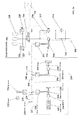
- FIG. 1 illustrates an apparatus for moving cargo 100 according to an embodiment.
- At least one load 104, 108 is connected to the bus.
- Each of the loads connects to the bus to transform electrical energy from the bus into movement of a cargo with respect to the apparatus.
- An energy recovery system 114 comprises a transformer 112 for transforming energy between electrical energy of the bus and potential energy of a hydraulic accumulator 110.
- a controller controls the transformer and the hydraulic accumulator to store electrical energy from the bus as potential energy to the hydraulic accumulator and supply the potential energy stored in the hydraulic accumulator as electrical energy to the at least one load.
- the functions of the apparatus comprising drive function 104, cargo movement function 108 and the energy recovery system 114 receive power from the bus, thereby they are loads connected to the bus.
- the drive function 104 and the cargo movement function are each configured to transform electrical energy from the bus into mechanical movement.
- the drive function moves the apparatus on a surface, and a cargo movement function moves a cargo carried by the apparatus with respect to the apparatus.
- the apparatus comprises a power supply 102 connected to a bus 106 for transmission of electrical energy.
- the power supply may comprise a diesel engine, a combustion engine, an electrical generator supplying DC or AC, or an electrical connection through which electrical energy may be supplied to the bus in the form of AC or DC current.
- Examples of the electrical connection comprise a socket, a cable reel or a busbar system to the electric mains.
- the power supply provides electrical energy to the bus.
- the power supply may comprise energy transforming means to transform energy into electrical energy.
- energy transforming means to transform energy into electrical energy.
- a combustion engine and a diesel engine may be provided with a generator to transform the mechanical movement of the engine into electrical energy.
- the bus comprises a transmission bus of electrical energy in the form of DC current.
- the bus may comprise a DC-rail, DC-busbar or DC-link.
- the bus is connectable by various functions of the apparatus, thereby forming an intermediate circuit between the functions and/or loads connected to the bus.
- the DC-bus may provide an intermediate circuit to functions and/or loads of the apparatus connected to the DC-bus via inverters.
- Each of the inverters transforms the DC from the DC-bus into AC, thereby performing DC/AC conversion.
- the DC/AC conversion may be optimized according to the specific requirement of each function, e.g. in terms of frequency, voltage, and/or current provided by the inverter.
- the power supply feeds energy via the bus to a plurality of functions connected to the bus. These functions include but are not limited to the drive function 104, cargo movement function 108 and an energy recovery system 114.
- the plurality of functions is connected to the bus so as to receive electrical energy supplied from the power supply.
- the drive function provides movement of the apparatus.
- the movement of the apparatus may be provided in a planar surface, for example in a port area.
- the drive function may comprise determining a direction of movement of the apparatus, i.e. steering, and moving the apparatus to the determined direction. Accordingly, the direction may be determined as forward, backward or to either side, left or right, of the apparatus.
- the drive function may comprise one or more wheels and an energy transformer for receiving electrical energy from the bus and transforming the received electrical energy into movement of the wheels.
- the transformer may provide transforming the DC received from the bus into mechanical movement of the wheels.
- the direction of movement may be determined in the drive function by a steering wheel that may turn the wheels to provide movement of the apparatus into the determined direction.
- the turning may comprise turning one or more of the wheels towards the determined direction and/or setting the rotational speeds of the one or more wheels to facilitate turning.
- the cargo movement function may comprise a support for receiving a cargo to be moved and an energy transformer for receiving electrical energy from the bus and transforming the received electrical energy into movement of the cargo with respect to the apparatus.
- the support may comprise a hoist, a fork, or a spreader, for example which support the cargo such that the cargo may be picked up and moved with respect to the apparatus.
- the cargo may comprise e.g. a freight container movable between different modes of transportation, e.g. transportation by sea and land, thus between ships and trucks.
- the freight containers may be provided in various sizes that are standardized and defined in International Organization for Standardization (ISO) 6346.
- the movement of the cargo with respect to the apparatus may be provided by lifting the cargo.
- the movement of the cargo in the direction perpendicular to the planar surface of movement the apparatus may comprise lifting the cargo.
- the movement of the cargo in the direction parallel to the planar surface of movement the apparatus may comprise increasing or decreasing a distance measured between the cargo and any part of the cargo moving apparatus in the direction parallel to the planar surface of movement of the apparatus. It should be appreciated that the increase or decrease of distance is performed with respect to the parts of the apparatus that are not moving with the cargo, thus not including the part of the cargo-moving apparatus supporting the cargo.
- the energy recovery system 114 may comprise energy storage 110 and a transformer 112.
- the transformer provides transformation of energy between the bus and the energy storage. Accordingly, in an embodiment energy in the bus is in different form than the energy in the energy recovery system, the transformer provides transformation between the different forms.
- the energy storage comprises one or more hydraulic accumulators 110 that store energy as potential energy. Then, the transformer provides transformation of electrical energy in the bus into potential energy of the hydraulic accumulator.
- the hydraulic accumulator comprises potential energy stored in a pressurised fluid.
- the fluid may comprise gas or a liquid.
- a hydraulic accumulator storing energy in pressurized liquid comprise a weight-loaded and a spring-loaded accumulator, for example.
- the hydraulic accumulators storing energy in pressurized gas comprise a piston type, bladder type, and membrane accumulator, for example.
- the hydraulic accumulator stores energy in pressurised gas.
- the hydraulic accumulator may comprise separate spaces for the gas and for a liquid used to pressurize the gas.
- the spaces may be separated by a membrane as in a bladder type or membrane hydraulic accumulator or with a piston as in the piston type accumulator, so as to prevent mixing up the gas and the liquid.
- the energy recovery system may further comprise a controller 116 comprising memory 118.
- the controller connects to the transformer and the hydraulic accumulator by electric connections which may provide analog or digital transmission of signals and/or messages between the controller and the transformer and the hydraulic accumulator.
- the controller may be a Programmable Logic Controller (PLC) comprising program code stored in the memory.
- the program code may provide control commands to the transformer and the hydraulic accumulator and processing of signals received from the transformer and the hydraulic accumulator.
- the controller may comprise a processor communicating with the memory to receive the program code or portions of the program code to be executed at the processor.
- the control of the energy recovery system comprising the transformer and the hydraulic accumulator may be provided by the execution of the program code or one or more portions of the program code stored in the memory which cause the controller to process signals received from the transformer and hydraulic accumulator and control their operation on the basis of the processing by transmitting signals to the hydraulic accumulator and transformer.
- the apparatus 100 of Figure 1 comprises a gantry crane, a straddle carrier, fork lift or lifttruck comprising a drive function, e.g. gantry drive 104 that provides movement of the gantry crane, a hoist winch 108 for moving cargo and an energy recovery system 114 including one or more hydraulic accumulators 110 for storing energy from the DC-rail 106 and supplying energy to the DC-rail.
- a drive function e.g. gantry drive 104 that provides movement of the gantry crane, a hoist winch 108 for moving cargo
- an energy recovery system 114 including one or more hydraulic accumulators 110 for storing energy from the DC-rail 106 and supplying energy to the DC-rail.
- Figure 2a illustrates a bus 260 for transmission of electrical energy to functions providing movement of the apparatus and the cargo, and an energy recovery system 200 connected to the bus according to an embodiment.
- the bus and energy recovery system of Figure 2a may be included in the apparatus of Figure 1 , for example.
- a diesel engine 232 is operated to drive a generator 234 of AC current.
- the generated current is fed to an inverter 235 that converts the AC current from the generator into DC current that is fed to a DC-rail.
- the DC-rail 260 provides transmission of electrical energy to a plurality of functions 237, 239 and the energy recovery system of the apparatus.
- Each of the plurality of functions and the energy recovery system is connected to the DC-rail to receive power. Accordingly, each of the plurality of functions and the energy recovery system may comprise a load connected to the DC-rail.
- the bus provides transmission of electrical energy to a cargo movement function 237 and a drive function 239.
- the cargo movement function may comprise a hoist winch 242 connected to an electric motor, the hoist motor, 246 that drives the hoist winch 242 via a gearbox 244.
- the hoist motor is powered by the hoist inverter 238 converting DC from the bus to AC and feeding the AC to the hoist motor.
- a hoist brake 248 is connected to the hoist motor to mechanically decelerate the hoist motor and thereby the movement of the hoist winch driven by the hoist motor.
- the hoist brake may be connected either to the gearbox 244 or the hoist winch 242, to decelerate the hoist winch.
- the drive function comprises one or more wheels 250 connected to an electric motor 256, the gantry motor that drives the wheel via a gearbox 254.
- the gantry motor is powered by the gantry inverter 240 converting DC from the bus to AC and feeding the AC to the gantry motor.
- a gantry brake 252 is connected to the wheel between the gearbox and the wheel to mechanically decelerate the rotational movement of the wheel. The deceleration of the gantry brake is transformed via the gearbox into deceleration of the gantry motor.
- the gantry brake may be connected to the gearbox 254 or the wheels 250, to decelerate the wheels.
- a brake resistor 236 is connected to the DC-rail to provide dissipation of excess energy from the bus as heat.
- the brake resistor may connect the DC-rail via a brake chopper 239 that allows connecting the brake resistor to the DC-rail when needed, for example when there is excess energy in the DC-rail.
- the operation of one or both of the hoist motor and the gantry motor may be reversed and they may operate as generators of electrical energy.
- the electrical energy generated by the generator may be AC or DC.
- the bus comprises a DC-rail the generated AC must be converted by an inverter to be supplied to the DC-rail.
- inverters may be omitted.
- the movement of the hoist winch may drive the hoist motor that transforms the movement into electrical energy in the form of AC.
- the generated AC is fed to the hoist inverter 238 for the generated AC to be converted into DC and to be supplied to the DC-rail.
- the movement of the wheel may drive the gantry motor that transforms the movement into electrical energy in the form of AC.
- the generated AC is fed to the gantry inverter 240 for the generated AC to be converted into DC and to be supplied to the DC-rail.
- the energy recovery system connects to the DC-rail via an inverter converting the DC to AC.
- the AC from the inverter is fed to the electric motor 204 that drives a hydraulic pump 206
- the electric motor provides transformation of electrical energy into mechanical energy by using the AC from the inverter to rotate a drive shaft.
- the hydraulic pump connects to a hydraulic tank comprising hydraulic fluid via a hydraulic line.
- the hydraulic pump is driven by the drive shaft of the electric motor.
- the drive shaft provides a common axis that connects the hydraulic pump and the electric motor.
- the hydraulic pump may connect to the drive shaft via a mechanical coupling.
- a gear box e.g. reduction gear may be used to connect the hydraulic pump to the drive shaft. Accordingly, the hydraulic pump provides transformation of mechanical energy from the electric motor into movement of the hydraulic fluid.
- the hydraulic pump comprises a fixed displacement pump, where a maximum volume flow rate of fluid per rotation (V rot ) of the pump is fixed.
- a fixed displacement pump comprise but are not limited to a gear pump, a rotary vane pump, a screw pump, bent axis pump, and axial piston pump using a swash plate.
- the hydraulic pump sucks the hydraulic fluid from the tank and pushes the hydraulic fluid to one or more hydraulic accumulators 218 connected to the hydraulic pump by a hydraulic line.
- a valve 216 may be provided between the hydraulic pump and the hydraulic accumulators.
- the displacement of the hydraulic pump may be used to control the amount of hydraulic fluid displaced by the pump by the suction and pushing per a revolution of the pump.
- the valve 216 may comprise a 2/2-way directional valve 2/2 proportional valve or a servo valve, for example.
- 2/2 proportional valve When the hydraulic fluid is pushed to the hydraulic accumulators by the hydraulic pump, the check function of the valve is set open towards the hydraulic accumulators, to provide flow of the hydraulic fluid to the hydraulic accumulators. When the hydraulic accumulators are discharged, hydraulic fluid is pushed to the hydraulic pump and the check function of the valve is set open towards the hydraulic pump.
- One or more sensors 220 and 222 may be connected to the hydraulic accumulators and arranged to detect an amount of potential energy stored in the hydraulic accumulators. Each of the sensors may connect to the hydraulic accumulators on a hydraulic line.
- the amount of potential energy stored in the hydraulic accumulators may comprise a charging level of the hydraulic accumulators.
- a minimum charging level indicates that the hydraulic accumulators need to be charged. When the charging level is at minimum, the hydraulic accumulators need to be charged before they can be used to supply energy to the bus.
- a maximum charging level indicates that the hydraulic accumulators store a maximum amount of potential energy. When the charging level is at its maximum the hydraulic accumulators cannot be charged and their charging must be stopped to avoid damaging the hydraulic accumulators.
- the sensors may comprise pressure switches, where a first pressure switch is arranged to detect when the pressure of the hydraulic accumulators indicates a minimum charging level of the hydraulic accumulators, and a second sensor is arranged to detect when the pressure of the hydraulic accumulators indicates a maximum charging level of the hydraulic accumulators.
- the pressure indicating a minimum charging level may be 100 bars and the pressure indicating a maximum charging level may be 400 bars.
- the energy recovery system may comprise a safety valve 212 that provides a hydraulic line to the tank for the hydraulic fluid flowing between the hydraulic accumulator and the hydraulic pump.
- the safety valve is switched open, when a pressure exceeds a threshold pressure, whereby the hydraulic fluid discharges through the safety valve to the tank.
- the threshold pressure may be a pressure that is greater than a pressure of the hydraulic accumulators at a maximum charging level of the hydraulic accumulators.
- the energy recovery system may comprise a filter 214 to keep the hydraulic fluid clean.
- the filter may be connected to a return path of the hydraulic fluid from the hydraulic accumulator and/or a return path of the hydraulic fluid from the safety valve.
- the filter is connected to a hydraulic line between the hydraulic accumulators and the hydraulic pump, via the safety valve. In this way the hydraulic fluid discharging through the safety valve may be cleaned.
- the filter is connected to a hydraulic line between the hydraulic pump and the tank. In this way the hydraulic fluid from the pump may be filtered.
- the operation of the hydraulic pump and the electric motor may be reversed so that they may be used to transform energy between electrical energy and the flow of hydraulic fluid in both directions.
- the hydraulic pump may comprise a hydraulic motor.
- the electric motor may comprise a generator of electric current.
- hydraulic fluid discharging from the hydraulic accumulators may drive the hydraulic motor that transforms the flow of the hydraulic fluid into mechanical movement.
- the hydraulic motor is connected to the generator and the mechanical movement from the hydraulic motor is transferred to the generator.
- the generator is driven by the mechanical movement from the hydraulic motor and the generator transforms the mechanical movement into electrical energy.
- the electrical energy may comprise AC or DC.
- the generator generates AC that is fed to the inverter 202 to be supplied to the DC-rail as DC.
- the energy recovery system comprises a controller 226 for controlling the operation of the energy recovery system.
- the controller connects to the energy recovery system to receive information on the amount of potential energy stored in the energy recovery system and to determine whether the energy recovery system is operated to store energy from the bus or whether energy recovery system is operated to supply energy to the bus.
- the controller connects electrically to the pressure switches 222 and 220 to receive information on the amount of potential energy stored in the hydraulic accumulator.
- the controller connects electrically to the 2/2-way directional valve to control the valve to enable the flow of hydraulic fluid to the hydraulic accumulator or from the hydraulic accumulator or to stop the flow of hydraulic fluid.
- the energy recovery system may comprise an encoder connected to the electric motor.
- the encoder determines the rotational speed of the electric motor and connects electrically to the controller to provide the rotational speed as an electric signal to a controller.
- the controller sets the rotational speed of the electric motor via the connection to the electric motor.
- the energy recovery system may further comprise a volume flow rate sensor 217 connected to the 2/2-way directional valve.
- the volume flow rate sensor provides the controller information of the volume flow rate passing through the 2/2-way-directional valve on an electric connection between the volume flow rate sensor and the controller.
- the controller 226 may connect electrically to means 223 for determining electrical properties of the DC-bus 260.
- the means 223 may comprise a device that measures e.g. voltage of the DC-bus, and/or any other electrical property of the DC. Based on the measured electrical properties a power requirement of the DC-bus may be determined.
- the means 223 may have the necessary processing power to determine the power requirement and output the power requirement to be used by the controller 226 in controlling the energy recovery system.
- the measured electrical properties or an indication of the measured electrical properties may be output to the controller 226 that determines the power requirement of the DC-bus on the basis of the information received from the means 223.
- FIG. 2b illustrates an energy recovery system 201 similar to that described with reference to Figure2a .
- the energy recovery system of Figure 2b uses the same components as described with reference to Figure 2a above and denoted by same reference numerals.
- the energy recovery system of Figure 2b the same hydraulic pump described above with reference to Figure 2a may be used with the difference that the hydraulic pump of Figure 2b comprises a variable displacement hydraulic pump 276 controlled by a controller 296 connected electrically to the variable displacement hydraulic pump.
- the volume flow rate per rotation may be varied.
- the controller controls the displacement of the variable displacement pump via the electrical connection.
- a variable displacement pump comprise but are not limited to a rotary vane pump, a bent axis pump, axial piston pump using a swash plate.
- the displacement of the pump may be optimized.
- the torque provided by the pump may be controlled, despite a change in the pressure of the hydraulic accumulator. This minimizes losses in the electric motor and increase overall response time of the system.
- the displacement can be set so that the rotation speed of the pump and therefore the rotation speed of the electric motor is in the range of high efficiency.
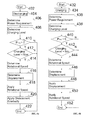
- Figure 3 illustrates a method of operating an energy recovery system according to an embodiment. The method may be performed by a controller of the energy recovery system, for example.
- electrical energy from a bus is stored into potential energy to a hydraulic accumulator and potential energy stored into the hydraulic accumulator is supplied as electrical energy to the bus to provide power to one or more functions of an apparatus for moving cargo.
- the method described below with Figure 3 may be a method in a sequence of methods according to Figure 4 .
- the energy stored from the bus according to the method of Figure 4 may be supplied as energy to the bus in a method according to Figure 4 executed next in the sequence.
- This provides energy stored from lowering a hoist winch in a gantry crane to be used to supply power to the wheels of the gantry crane and vice versa.
- energy stored from one function connected to the bus may be used to power other functions of the apparatus by storing electrical energy from the bus as potential energy to the hydraulic accumulator; and by supplying the potential energy stored in the hydraulic accumulator as electrical energy to the functions of the apparatus being powered by the bus.
- the energy recovery system may be the energy recovery system comprising a hydraulic accumulator described above with reference to Figures 2a and 2b .
- the method is described as deployed in a gantry crane comprising a bus for transmission of electrical energy to different functions of the gantry crane. These functions may comprise the hoist winch and wheels as described in Figure 2a .
- the method begins in 302, where the energy recovery system as described above with reference to Figures 2a and 2b is deployed in a gantry crane.
- the energy recovery system enables cutting the peak power requirements of the main power supply of the gantry crane e.g. diesel engine. This is because, during the operation of the gantry crane, lifting and driving of the gantry may be powered from the energy stored in the energy recovery system.
- the energy recovery system is used as energy source, power is not needed from the main power supply. This provides decreasing the fuel consumption of diesel engines since they may be idling or stopped for the time energy is supplied from the energy recovery system.
- a power requirement of the bus is determined.
- the power requirement may be determined by measuring the electrical properties of the bus, for example the voltage.
- the power requirement may be 0, when the power level of the bus is sufficient to provide power to all the functions of the gantry crane and there is no excess power in the bus to be stored in the energy recovery system.
- the power requirement may be greater than 0, when the bus has excess power to be stored and the power requirement may be less than 0, when more power should be supplied to the bus to power the functions of the gantry crane, e.g. when the hoist winch is used to lift a cargo container and/or the wheels need more power e.g. during acceleration.
- a charging level of a hydraulic accumulator is determined.
- the determining may comprise receiving information of the amount of potential energy stored in the hydraulic accumulator.
- a controller of the energy recovery system may receive information of the pressure of the hydraulic accumulator from one or more sensors connected to the hydraulic accumulator.
- the information may comprise the pressure value, or an indicator of the pressure which the controller may use to determine a pressure or a range of pressures comprising the pressure currently prevailing in the hydraulic accumulator.
- the information may be received as a signal comprising the information, e.g. an electric signal.
- the controller determines on the basis of the received information a charging level of the hydraulic accumulator.
- the charging level may comprise whether the hydraulic accumulator is at minimum, maximum and/or partially charged.
- the energy recovery system comprises a first pressure switch detecting a minimum pressure and a second pressure switch detecting a maximum pressure
- the minimum pressure comprises a pressure
- the hydraulic accumulator is discharged and the maximum pressure indicates a pressure where the hydraulic accumulator is fully charged.
- the controller receives a signal indicating detection of the minimum pressure from the pressure switch for detecting the minimum value pressure.
- the controller receives a signal indicating detection of the maximum pressure from the pressure switch. In this way the controller may determine charging levels of the hydraulic accumulator on the basis of the signals received from the pressure switches.
- the bus comprises no excess power that could be stored to the energy recovery system and there is no need for more power in the functions of the gantry crane or straddle carrier supplied by the bus, and the process proceeds to end 322.
- the power requirement is 0, the energy recovery system is stopped and it is not used to store or supply energy.
- the process proceeds to 310.
- the bus may comprise excess power received from deceleration.
- the deceleration may comprise decelerating movement of a hoist winch and/or wheels of the gantry crane.
- the energy received from the deceleration may be transformed into electrical energy and supplied to the DC-rail.
- the potential energy stored in the height of the cargo may be transformed into electrical energy and supplied to the bus.
- This may be performed in the example of Figure 2a , when the potential energy stored in the cargo lifted by hoist winch is released by the hoist winch when the cargo is lowered, whereby the hoist winch drives the hoist motor via the gearbox.
- the hoist motor operating as a generator converts the mechanical movement from the hoist winch to electrical energy.
- the AC generated by the hoist motor is fed to the hoist inverter that converts the AC to DC and supplies the DC to the bus.
- the bus may comprise excess power received from decelerating movement of the gantry crane. This may happen, when the gantry crane is engaged in a movement, whereby the gantry crane has kinetic energy stored in its movement. Upon deceleration of the movement, the kinetic energy may be transformed into electrical energy and supplied to the bus. This may be performed in the example of Figure 2a , when the kinetic energy stored in the movement of the wheels may be released by the decelerating wheels, whereby the decelerating wheels drive the gantry motor via the gearbox and the gantry brake.
- the gantry motor operating as a generator converts the mechanical movement from the wheels into electrical energy.
- the AC generated by the gantry motor is fed to the gantry inverter that converts the AC to DC and supplies the DC to the bus.
- the determining may be omitted and the process may proceed from 310 directly to 318.
- the determining in 312 may be performed. In this way possible errors in the determined power requirement may be determined, e.g. if the determined power requirement is not valid value. Accordingly, if the power requirement is not less than 0, it may be determined that an error situation has occurred and the process continues to end 322. Otherwise the process continues to 318.
- the charging level determined in 306 is greater than a minimum charging level of potential energy in the hydraulic accumulator.
- the minimum charging level may be determined as a pressure value.
- the hydraulic accumulator has potential energy that may be supplied to the bus and the process proceeds to 320 to discharge the hydraulic accumulator. Otherwise the process proceeds to end 322, since the hydraulic accumulator may be determined as discharged, in which case, the energy recovery system cannot supply electrical energy to the bus even if the power requirement is less than 0 and indicates that more power is needed in the bus.
- the charging level determined in 306 is less than a maximum charging level of potential energy in the hydraulic accumulator.
- the maximum charging level may be determined as a pressure value.
- the process proceeds to 316 to charge the hydraulic accumulator. Otherwise the hydraulic accumulator is determined as fully charged and thereby no more energy may be stored in the hydraulic accumulator, and the process proceeds to end 322.
- the hydraulic accumulator is charged by the electrical energy being transformed into a flow of hydraulic fluid into the hydraulic accumulator.
- the transformation comprises an electric motor connected to the bus and driving a hydraulic pump that pumps hydraulic fluid from a tank into the hydraulic accumulator.
- the charging may continue as long as there is excess power in the bus to be stored in the hydraulic accumulator or the hydraulic accumulator is not full, in which case the process ends in 322.
- step 304 described above may be continuously performed, when the hydraulic accumulator is charged to determine whether the bus has excess power to be stored into the potential energy of the hydraulic accumulator.
- step 306 described above may be continuously performed, when the hydraulic accumulator is charged to determine whether the charging level of the hydraulic accumulator and when the hydraulic accumulator reaches the maximum charging level.
- Figures 4a and 4b illustrate a method of operating a variable displacement pump of an energy recovery system according to an embodiment.
- a transition of the energy recovery system from discharging to charging is described.
- a transition of the energy recovery system from charging into discharging is described.
- the methods provide decreasing latency involved in changing the operation from storing to supplying and vice versa. Accordingly, the method of Figure 4a may be performed after the step 320 of Figure 3 to reduce a latency of a transition between discharging and charging, and the method of Figure 4b may be performed after the step 316 of Figure 3 to reduce latency of a transition between charging and discharging.
- the energy recovery system in methods of Figures 4a and 4b may be the energy recovery system comprising a hydraulic accumulator described in Figure 2b for example.
- the methods may be performed by a controller of the energy recovery system, for example.
- Figures 4a and 4b are described as deployed in a gantry crane comprising a bus for transmission of electrical energy to different functions of the gantry crane. These functions may comprise the hoist winch and wheels as described in Figure 2a .
- the process of Figure 4a starts in 402, where the energy recovery system is deployed into the gantry crane and the hydraulic accumulator of the energy recovery system is charged up to a charging level to supply electrical energy to the bus, to power the hoist winch and/or the wheels.
- the potential energy is discharged from the hydraulic accumulator, transformed into electrical energy and supplied into the bus to be used by the hoist winch and the wheels of the apparatus.
- the discharging may be performed as explained above with reference to step 320 of Figure 3 , for example.
- a power requirement of the bus is determined similar to step 304 of Figure 3 .
- a charging level of the hydraulic accumulator is determined similar to step 306 of Figure 3 .
- step 410 it is determined whether the power requirement is greater than 0, similar to step 310 in Figure 3 .
- the bus comprises excess power and the process proceeds to 412.
- the charging level determined in 408 is less than a maximum charging level of potential energy in the hydraulic accumulator similar to step 314 of Figure 3 .
- the charging level is less than a maximum, more energy may be stored to the hydraulic accumulator, and the hydraulic accumulator may be charged. If the charging level is less than the maximum charging level the process proceeds to 414, to charge the hydraulic accumulator. Otherwise the process proceeds to end 422.
- a rotational speed of the electric motor is determined to charge the hydraulic accumulator.
- the rotation speed of the electric motor is determined based on the wanted power level and the pressure level in the accumulator.
- the rotation speed can be set to be the maximum rotation speed of the pump or lower speed based on below equations, which may be predefined.
- a hydraulic accumulator storing potential energy in a pressurised fluid, e.g. gas, of an energy recovery system is designed with a maximum operating pressure
- the hydraulic accumulator may store and a minimum pressure of the hydraulic accumulator at which the hydraulic accumulator may still drive the hydraulic pump with needed power level, when the hydraulic fluid is discharged from the hydraulic accumulator to the hydraulic pump.
- a rotational speed of the hydraulic-pump motor may be defined on the basis of the predefined equations (1) and (2), when the power consumed by the electric motor P is the power requirement determined in 406.
- a displacement of the hydraulic pump may be determined, when the hydraulic pump of the energy recovery system comprises a variable displacement hydraulic pump.
- this step may be omitted, and since the displacement is constant.
- the torque of the hydraulic pump is less or equal to a maximum torque of the electric motor driving the hydraulic pump or driven by the hydraulic pump. In this way the torque from the hydraulic pump may be kept at a range of efficiency of the electric motor, which provides efficient transformation of the energy from the hydraulic accumulator into electrical energy. In some cases limiting the torque may also provide increased operating life and/or maintenance interval of the electric motor.
- a displacement of the hydraulic pump may be determined as a volume displaced by the hydraulic pump per rotation of the pump.
- the hydraulic pump motor comprises an axial piston pump using a swash plate
- displacement may be determined as a swash plate angle.
- the swash plate angle may be determined as an angle between a rotating axis of the cylinder and the swash plate.
- the rotational speed determined in 414 may be set to the electric motor and the direction of rotation of the electric motor may be reversed.
- the setting may comprise transmitting a command to the electric motor comprising the rotational speed and the direction of rotation.
- the displacement determined in 416 is set gradually to the hydraulic pump. In this way the determined rotational speed in 414 may be achieved faster, as the displacement is set to the determined value only after the rotational speed has reached the determined value.
- variable displacement pump comprises an axial piston pump using a swash plate
- the swash plate angle is set by gradually setting the swash plate angle from 0 displacement to the determined displacement angle.
- the hydraulic pump has to be charged so that it can be used to provide power to the bus.
- the hydraulic accumulator cannot be used to supply energy to the bus, but the following operation mode must be the charging mode.
- the displacement of the pump may be set to 0 before the direction and speed of rotation of the hydraulic pump is set in 414. In this way the operation of the pump may be changed from a motor discharging the hydraulic accumulators, into a pump for charging the hydraulic accumulator.
- the charging may be started with only a small latency since only the displacement needs to be set into the value determined in 414.
- FIG. 4b illustrating a method of operating a variable displacement pump of an energy recovery system according to an embodiment and where the energy recovery system changes from charging to discharging.
- the process starts in 432, where the energy recovery system is deployed into the gantry crane and the hydraulic accumulator of the energy recovery system is not fully charged, thereby allowing charging.
- electrical energy is charged into the hydraulic accumulator, comprising transforming electrical energy from the bus into movement of hydraulic fluid into the hydraulic accumulator to be stored as potential energy of the hydraulic accumulator.
- the charging may be performed as explained above with reference to step 316 of Figure 3 , for example.
- a power requirement of the bus is determined similar to step 304 of Figure 3 .
- a charging level of the hydraulic accumulator is determined similar to step 306 of Figure 3 .
- step 440 it is determined whether the power requirement is less than 0 similar to step 312 Figure 3 . When the power requirement is less than 0, more power needs to be supplied to the bus and the process proceeds to 442. Otherwise the process proceeds to end 452.
- the hydraulic accumulator comprises enough potential energy that the potential energy may be transformed into electrical energy and supplied to the bus, to satisfy the need of power in the bus. Otherwise there is not enough energy to be supplied to the bus in the hydraulic accumulator and the process proceeds to end 452.
- Determining of the rotational speed in step 444 and determining of the displacement in step 446 may be performed as described above respective steps 414 and 416 with Figure 4a .
- the displacement may be set to the variable displacement pump, in a similar manner as described with step 420 of Figure 4a . However, as a difference to step 420, herein the displacement should be set directly to the determined value.
- variable displacement pump comprises an axial piston pump using a swash plate
- the swash plate angle is set to the determined displacement angle
- the rotational speed determined in 434 may be set to the electric motor and the direction of rotation of the electric motor may be reversed, similar to described in step 418 of Figure 4a .
- the power provided from the electric motor may be low compared to the power obtained when the electric motor is at the determined rotational speed.
- the displacement in step 448 of Figure 4b may be set greater than the determined displacement angle during the acceleration of the electric motor to the determined speed. In this way a greater torque from the hydraulic pump may be provided to the electric motor during acceleration of the electric motor and more power may be supplied to the bus already during the acceleration of the electric motor.
- the latency involved between setting the setting of the rotational speed and direction of the electric motor and the time when the determined rotational speed is actually reached may be employed in setting the displacement gradually, whereby the displacement of the variable displacement hydraulic pump may be increased to the determined value directly proportionally to the acceleration of the electric motor.
- An embodiment provides a computer program embodied on a distribution medium, comprising program instructions which, when loaded into an electronic apparatus, constitute an apparatus for moving cargo or at least part of the apparatus, e.g. the controller 226, 296, described earlier.
- the computer program may be in source code form, object code form, or in some intermediate form, and it may be stored in some sort of carrier, which may be any entity or device capable of carrying the program.
- carrier include a record medium, computer memory, read-only memory, electrical carrier signal, telecommunications signal, and software distribution package, for example.
- the computer program may be executed in a programmable logic controller, a single electronic digital computer or it may be distributed amongst a number of computers.
- the controller 226, 296 may also be implemented as one or more integrated circuits, such as application-specific integrated circuits ASIC. Other hardware embodiments are also feasible, such as a circuit built of separate logic components or a programmable logic circuit. A hybrid of these different implementations is also feasible. When selecting the method of implementation, a person skilled in the art will consider the requirements set for the size and power consumption of the controller 226, 296, necessary processing capacity, production costs, and production volumes, for example.
- the steps/points, signaling messages and related functions described above in Figures 3 , 4a and 4b are in no absolute chronological order, and some of the steps may be performed simultaneously or in an order differing from the given one. Other functions can also be executed between the steps or within the steps. Some of the steps or part of the steps can also be left out or replaced by a corresponding step or part of the step.
- the controller 227, 296 operations illustrate a procedure that may be implemented in one or more physical or logical entities.
- Apparatuses for moving cargo comprise not only prior art means, but also means for providing a bus for transmission of electrical energy, means for providing at least one load connected to the bus, said at least one load configured to transform electrical energy from the bus into movement of a cargo with respect to the apparatus, means for transforming energy between electrical energy of the bus and potential energy of a hydraulic accumulator, means for storing electrical energy from the bus as potential energy to the hydraulic accumulator, and means for supplying the potential energy stored in the hydraulic accumulator as electrical energy to the load.
- controller 226, 296 may be a software application, or a module, or a unit configured as arithmetic operation, or as a program (including an added or updated software routine), executed by an operation processor.
- Programs, also called program products, including software routines, applets and macros, can be stored in any apparatus-readable data storage medium and they include program instructions to perform particular tasks.
- routines may be implemented as added or updated software routines, application circuits (ASIC) and/or programmable circuits.
- software routines may be downloaded into an apparatus.
- the apparatus such as a controller, may be configured as a computer or a microprocessor, such as single-chip computer element, including at least a memory for providing storage area used for arithmetic operation and an operation processor for executing the arithmetic operation.
- An example of the operation processor includes a central processing unit.
- the memory may be removable memory detachably connected to the apparatus.
- kits can be prepared according different standards (electrical, mechanical) for different markets, models and sizes, and its installation is shorter with a good preparation and planning, which in turn gives a short down-time in production. Also maintenance is more fluent after upgrading, when known combination of parts are used, rather than using a selection of random choice for each upgrade.
- a kit for upgrading an apparatus for moving cargo may comprise a hydraulic accumulator for storing and supplying energy, an energy transforming means configured to transform energy between electrical energy and potential energy of the hydraulic accumulator, and controller means configured to control the transformer and the hydraulic accumulator to store electrical energy from the from the bus as potential energy to the hydraulic accumulator and supply the potential energy stored in the hydraulic accumulator as electrical energy.
- the transformation of energy between electrical energy may be provided as explained above with reference to the above Figures, e.g. any one Figures 1 , 2a and 2b .
- the transformation may be performed e.g. the transformer 112 of Figure 1 .
- the controller means may be provided as explained above with reference to the above Figures, e.g. any one Figures 1 , 2a and 2b .
- the Controller means may comprise the controller 116 of Figure 1 and/or PLC 226 Figure 2a or PLC 296 in Figure 2b .
- the hydraulic accumulator may be provided as explained above with reference to the above Figures, e.g. any one Figures 1 , 2a and 2b .
- the Controller means may comprise the hydraulic accumulator 110of Figure 1 .
- a method for upgrading an apparatus for moving cargo is provided using the kit for upgrading according to an embodiment.
- the kit is installed to the apparatus for moving cargo. It should be appreciated that upgrading an existing apparatus for moving cargo provides various advantages.
- an apparatus for moving cargo may be upgraded by a computer program embodied on a distribution medium, comprising program instructions which, when loaded into an electronic apparatus, constitute an apparatus for moving cargo or at least part of the apparatus, e.g. the controller 226, 296, described earlier.
Landscapes
- Engineering & Computer Science (AREA)
- Mechanical Engineering (AREA)
- Physics & Mathematics (AREA)
- Fluid Mechanics (AREA)
- General Engineering & Computer Science (AREA)
- Automation & Control Theory (AREA)
- Chemical & Material Sciences (AREA)
- Analytical Chemistry (AREA)
- Power Engineering (AREA)
- Fluid-Pressure Circuits (AREA)
- Control Of Conveyors (AREA)
Priority Applications (1)
| Application Number | Priority Date | Filing Date | Title |
|---|---|---|---|
| PL12192204T PL2594522T3 (pl) | 2011-11-21 | 2012-11-12 | Urządzenie, sposób, i produkt w postaci programu komputerowego do przemieszczania ładunku oraz zestaw do modernizowania urządzenia do przemieszczania ładunku i sposób modernizowania urządzenia do przemieszczania ładunku |
Applications Claiming Priority (1)
| Application Number | Priority Date | Filing Date | Title |
|---|---|---|---|
| FI20116157A FI124200B (en) | 2011-11-21 | 2011-11-21 | A device, method, and computer program product for moving a load, and a kit and method for updating a device for moving a load |
Publications (3)
| Publication Number | Publication Date |
|---|---|
| EP2594522A2 true EP2594522A2 (de) | 2013-05-22 |
| EP2594522A3 EP2594522A3 (de) | 2013-05-29 |
| EP2594522B1 EP2594522B1 (de) | 2017-08-02 |
Family
ID=47665788
Family Applications (1)
| Application Number | Title | Priority Date | Filing Date |
|---|---|---|---|
| EP12192204.1A Not-in-force EP2594522B1 (de) | 2011-11-21 | 2012-11-12 | Vorrichtung, Verfahren und Computerprogrammprodukt zum Bewegen von Fracht, und Satz und Verfahren zur Verbesserung einer Vorrichtung zum Bewegen von Fracht |
Country Status (4)
| Country | Link |
|---|---|
| US (1) | US9316238B2 (de) |
| EP (1) | EP2594522B1 (de) |
| FI (1) | FI124200B (de) |
| PL (1) | PL2594522T3 (de) |
Cited By (2)
| Publication number | Priority date | Publication date | Assignee | Title |
|---|---|---|---|---|
| ITTO20130989A1 (it) * | 2013-12-04 | 2015-06-05 | Re Mac Ut S R L | Sistema di recupero di energia, e relativo metodo |
| EP3628554A1 (de) * | 2018-09-28 | 2020-04-01 | Goodrich Corporation | Hydraulisches bremssystem und verfahren |
Families Citing this family (20)
| Publication number | Priority date | Publication date | Assignee | Title |
|---|---|---|---|---|
| US8718881B2 (en) * | 2009-09-11 | 2014-05-06 | Tmeic Corporation | Fuel efficient crane system |
| US9488193B2 (en) * | 2013-12-23 | 2016-11-08 | Eaton Corporation | Uninterruptible power supply systems using electrohydraulic energy storage |
| DE102015118535A1 (de) * | 2015-10-29 | 2017-05-04 | Terex MHPS IP Management GmbH | Schwerlaststapler |
| CN106284475B (zh) * | 2016-09-19 | 2018-08-14 | 太原理工大学 | 一种双电动机驱动的液压挖掘机 |
| WO2018119972A1 (zh) * | 2016-12-30 | 2018-07-05 | 徐州重型机械有限公司 | 起重机液压控制系统和起重机 |
| DE102017001203A1 (de) | 2017-02-09 | 2018-08-09 | Hydac International Gmbh | Antriebseinrichtung zur Energieversorgung hochbelasteter Elektromotoren |
| CN107606002B (zh) * | 2017-08-24 | 2019-12-10 | 武汉理工大学 | 龙门起重机运行机构制动性能检测装置及方法 |
| CN108423551B (zh) * | 2017-11-30 | 2019-08-13 | 中船华南船舶机械有限公司 | 一种起重机消除累积误差系统及消除累积误差方法 |
| CN108708423B (zh) * | 2018-05-25 | 2020-07-21 | 太原理工大学 | 一种液电混合驱动的多执行器回路 |
| BR112021000946A2 (pt) * | 2018-07-19 | 2021-04-20 | Energy Vault, Inc. | bloco e garra para uso em sistema e método de armazenamento e geração de energia e método de operação da garra |
| DE102019122956A1 (de) * | 2019-08-27 | 2021-03-18 | J.D. Neuhaus Holding Gmbh & Co. Kg | Fluidbetriebenes Hebezeug |
| CN115210170A (zh) | 2020-01-22 | 2022-10-18 | 能源库公司 | 包括阻尼自定心机构的抓取器 |
| IL299073A (en) | 2020-06-30 | 2023-02-01 | Energy Vault Inc | A system and method for energy storage and its supply |
| US12132312B2 (en) * | 2020-12-24 | 2024-10-29 | Energy Vault, Inc. | Energy storage system with elevator lift system |
| CA3206366A1 (en) | 2021-02-02 | 2022-08-11 | Andrea Pedretti | Energy storage system with elevator lift system |
| US12215676B2 (en) | 2021-07-07 | 2025-02-04 | Energy Vault, Inc. | Lift drive system for energy storage and delivery system |
| US20240391741A1 (en) * | 2021-09-24 | 2024-11-28 | Paccar Inc | Stand-alone electronic control of winches |
| CN116262588A (zh) | 2021-12-13 | 2023-06-16 | 能源库公司 | 能量储存和输送系统及方法 |
| CN115991431B (zh) * | 2023-03-24 | 2023-05-16 | 济宁四通工程机械有限公司 | 一种起重机液压控制系统 |
| US11982261B1 (en) | 2023-04-10 | 2024-05-14 | Energy Vault, Inc. | Energy storage and delivery system and method |
Family Cites Families (15)
| Publication number | Priority date | Publication date | Assignee | Title |
|---|---|---|---|---|
| DE2509228C3 (de) | 1975-03-04 | 1981-01-22 | Maschinenfabrik Augsburg-Nuernberg Ag, 8500 Nuernberg | Elektro-hydraulischer Antrieb für Hebezeuge |
| JP2809292B2 (ja) | 1992-05-01 | 1998-10-08 | 三菱電機株式会社 | 油圧駆動式発電装置 |
| DE19745810A1 (de) | 1997-10-16 | 1998-05-14 | Gerold Ing Grad Bieber | Freikolbenbrennkraftmaschine für kompaktes Stadtauto |
| JP2001197785A (ja) | 1999-11-04 | 2001-07-19 | Shin Caterpillar Mitsubishi Ltd | 回路装置 |
| HRP20030051A2 (en) | 2000-08-18 | 2004-02-29 | Bucher Hydraulics Ag | Hydraulic lift with an accumulator |
| US7554278B2 (en) * | 2006-06-13 | 2009-06-30 | Railpower Technologies Corp. | Load-lifting apparatus and method of storing energy for the same |
| US8408144B2 (en) * | 2006-10-04 | 2013-04-02 | The United States Of America, As Represented By The Administrator Of The U.S. Environmental Protection Agency | Hybrid locomotive regenerative energy storage system and method |
| US7843076B2 (en) | 2006-11-29 | 2010-11-30 | Yshape Inc. | Hydraulic energy accumulator |
| CN100427771C (zh) | 2006-12-14 | 2008-10-22 | 浙江大学 | 一种液压配重可变的节能液压升降系统 |
| US7856816B2 (en) | 2008-01-03 | 2010-12-28 | Eaton Corporation | Hydraulic brake energy regeneration system for electric energy storage and vehicle drive assist |
| US7900724B2 (en) * | 2008-03-20 | 2011-03-08 | Terex-Telelect, Inc. | Hybrid drive for hydraulic power |
| CN202007082U (zh) | 2009-06-15 | 2011-10-12 | 姚航 | 港口吊车液压节能系统 |
| DE102009037807A1 (de) * | 2009-08-18 | 2011-02-24 | Voith Patent Gmbh | Vorrichtung zum Heben und Senken von Lasten |
| CN201634332U (zh) | 2010-02-02 | 2010-11-17 | 中铁十一局集团第六工程有限公司 | 重型门式提梁机 |
| WO2012102654A1 (en) * | 2011-01-27 | 2012-08-02 | Parker Hannifin Ab | Hyraulic accumulator system |
-
2011
- 2011-11-21 FI FI20116157A patent/FI124200B/en not_active IP Right Cessation
-
2012
- 2012-11-12 PL PL12192204T patent/PL2594522T3/pl unknown
- 2012-11-12 EP EP12192204.1A patent/EP2594522B1/de not_active Not-in-force
- 2012-11-19 US US13/681,113 patent/US9316238B2/en not_active Expired - Fee Related
Cited By (3)
| Publication number | Priority date | Publication date | Assignee | Title |
|---|---|---|---|---|
| ITTO20130989A1 (it) * | 2013-12-04 | 2015-06-05 | Re Mac Ut S R L | Sistema di recupero di energia, e relativo metodo |
| WO2015083095A1 (en) * | 2013-12-04 | 2015-06-11 | Re.Mac.Ut. S.R.L. | Energy recovery system, and method thereof |
| EP3628554A1 (de) * | 2018-09-28 | 2020-04-01 | Goodrich Corporation | Hydraulisches bremssystem und verfahren |
Also Published As
| Publication number | Publication date |
|---|---|
| US20130125540A1 (en) | 2013-05-23 |
| US9316238B2 (en) | 2016-04-19 |
| FI20116157A7 (fi) | 2013-05-22 |
| EP2594522B1 (de) | 2017-08-02 |
| EP2594522A3 (de) | 2013-05-29 |
| FI124200B (en) | 2014-04-30 |
| PL2594522T3 (pl) | 2017-11-30 |
Similar Documents
| Publication | Publication Date | Title |
|---|---|---|
| US9316238B2 (en) | Apparatus, method and computer program product for moving cargo, and a kit and method for upgrading an apparatus for moving cargo | |
| CN102241379B (zh) | 节能型行走式液压搬运机械 | |
| US7378808B2 (en) | Electric drive system having DC bus voltage control | |
| US8209975B2 (en) | Arrangement for operating a hydraulic device | |
| EP2373526B1 (de) | Bremsenergierückgewinnungssystem für ein fahrzeug | |
| KR101823168B1 (ko) | 하이브리드 구동 시스템을 가진 크레인 | |
| CN102171061A (zh) | 具有混合驱动装置的工具 | |
| US8914177B2 (en) | Hybrid wheel loader | |
| WO2003093046A2 (en) | Hybrid vehicle with combustion engine/electric motor drive | |
| KR20100125430A (ko) | 전기 견인 시스템 및 방법 | |
| CN104763696A (zh) | 一种用于工业车辆的电控液压驱动系统 | |
| CN103661353A (zh) | 用于具有增压器和附件的车辆驱动系统的控制系统 | |
| CN101011942B (zh) | 一种混合动力工业车辆 | |
| CN102712316A (zh) | 用于具有混合电动系统的车辆上设备的控制系统 | |
| CN113147359A (zh) | 作业机械的动力系统和控制方法 | |
| WO2011115615A1 (en) | Vehicle with primary and secondary air system control for electric power take off capability | |
| CN112639289A (zh) | 用于混合动力车辆的双空气压缩机 | |
| JP2012016993A (ja) | ハイブリッド型建設機械における制御システム | |
| CN101580207A (zh) | 港口吊车液压节能系统 | |
| JP5616086B2 (ja) | 車両搭載用クレーンの発電機駆動制御装置 | |
| CN104712603B (zh) | 一种汽车起重机的液压系统、汽车起重机及控制方法 | |
| CN107109823B (zh) | 作业机械的驱动控制系统、具备该驱动控制系统的作业机械、及其驱动控制方法 | |
| EP4101695B1 (de) | Stromverwaltungssystem für eine transportkühleinheit | |
| CN110696745A (zh) | 一种大型线缆盘运输车的电气系统 | |
| CN201009756Y (zh) | 一种混合动力工业车辆 |
Legal Events
| Date | Code | Title | Description |
|---|---|---|---|
| PUAL | Search report despatched |
Free format text: ORIGINAL CODE: 0009013 |
|
| PUAI | Public reference made under article 153(3) epc to a published international application that has entered the european phase |
Free format text: ORIGINAL CODE: 0009012 |
|
| AK | Designated contracting states |
Kind code of ref document: A2 Designated state(s): AL AT BE BG CH CY CZ DE DK EE ES FI FR GB GR HR HU IE IS IT LI LT LU LV MC MK MT NL NO PL PT RO RS SE SI SK SM TR |
|
| AX | Request for extension of the european patent |
Extension state: BA ME |
|
| AK | Designated contracting states |
Kind code of ref document: A3 Designated state(s): AL AT BE BG CH CY CZ DE DK EE ES FI FR GB GR HR HU IE IS IT LI LT LU LV MC MK MT NL NO PL PT RO RS SE SI SK SM TR |
|
| AX | Request for extension of the european patent |
Extension state: BA ME |
|
| RIC1 | Information provided on ipc code assigned before grant |
Ipc: E02F 9/20 20060101ALI20130419BHEP Ipc: B66C 13/28 20060101AFI20130419BHEP Ipc: E02F 9/22 20060101ALI20130419BHEP Ipc: B66F 9/22 20060101ALI20130419BHEP Ipc: F15B 21/14 20060101ALI20130419BHEP Ipc: B66F 9/24 20060101ALI20130419BHEP |
|
| 17P | Request for examination filed |
Effective date: 20131128 |
|
| RBV | Designated contracting states (corrected) |
Designated state(s): AL AT BE BG CH CY CZ DE DK EE ES FI FR GB GR HR HU IE IS IT LI LT LU LV MC MK MT NL NO PL PT RO RS SE SI SK SM TR |
|
| 17Q | First examination report despatched |
Effective date: 20150316 |
|
| RAP1 | Party data changed (applicant data changed or rights of an application transferred) |
Owner name: KONECRANES GLOBAL CORPORATION |
|
| REG | Reference to a national code |
Ref country code: DE Ref legal event code: R079 Ref document number: 602012035256 Country of ref document: DE Free format text: PREVIOUS MAIN CLASS: B66C0013280000 Ipc: B66C0013180000 |
|
| GRAP | Despatch of communication of intention to grant a patent |
Free format text: ORIGINAL CODE: EPIDOSNIGR1 |
|
| RIC1 | Information provided on ipc code assigned before grant |
Ipc: F15B 21/14 20060101ALI20170110BHEP Ipc: B66C 13/18 20060101AFI20170110BHEP Ipc: F15B 1/02 20060101ALI20170110BHEP |
|
| INTG | Intention to grant announced |
Effective date: 20170202 |
|
| GRAS | Grant fee paid |
Free format text: ORIGINAL CODE: EPIDOSNIGR3 |
|
| GRAJ | Information related to disapproval of communication of intention to grant by the applicant or resumption of examination proceedings by the epo deleted |
Free format text: ORIGINAL CODE: EPIDOSDIGR1 |
|
| GRAL | Information related to payment of fee for publishing/printing deleted |
Free format text: ORIGINAL CODE: EPIDOSDIGR3 |
|
| INTC | Intention to grant announced (deleted) | ||
| GRAR | Information related to intention to grant a patent recorded |
Free format text: ORIGINAL CODE: EPIDOSNIGR71 |
|
| GRAA | (expected) grant |
Free format text: ORIGINAL CODE: 0009210 |
|
| AK | Designated contracting states |
Kind code of ref document: B1 Designated state(s): AL AT BE BG CH CY CZ DE DK EE ES FI FR GB GR HR HU IE IS IT LI LT LU LV MC MK MT NL NO PL PT RO RS SE SI SK SM TR |
|
| INTG | Intention to grant announced |
Effective date: 20170628 |
|
| REG | Reference to a national code |
Ref country code: GB Ref legal event code: FG4D |
|
| REG | Reference to a national code |
Ref country code: CH Ref legal event code: EP Ref country code: AT Ref legal event code: REF Ref document number: 914216 Country of ref document: AT Kind code of ref document: T Effective date: 20170815 |
|
| REG | Reference to a national code |
Ref country code: IE Ref legal event code: FG4D |
|
| REG | Reference to a national code |
Ref country code: DE Ref legal event code: R096 Ref document number: 602012035256 Country of ref document: DE |
|
| REG | Reference to a national code |
Ref country code: NL Ref legal event code: FP |
|
| REG | Reference to a national code |
Ref country code: SE Ref legal event code: TRGR |
|
| REG | Reference to a national code |
Ref country code: AT Ref legal event code: MK05 Ref document number: 914216 Country of ref document: AT Kind code of ref document: T Effective date: 20170802 |
|
| REG | Reference to a national code |
Ref country code: LT Ref legal event code: MG4D |
|
| PG25 | Lapsed in a contracting state [announced via postgrant information from national office to epo] |
Ref country code: AT Free format text: LAPSE BECAUSE OF FAILURE TO SUBMIT A TRANSLATION OF THE DESCRIPTION OR TO PAY THE FEE WITHIN THE PRESCRIBED TIME-LIMIT Effective date: 20170802 Ref country code: HR Free format text: LAPSE BECAUSE OF FAILURE TO SUBMIT A TRANSLATION OF THE DESCRIPTION OR TO PAY THE FEE WITHIN THE PRESCRIBED TIME-LIMIT Effective date: 20170802 Ref country code: NO Free format text: LAPSE BECAUSE OF FAILURE TO SUBMIT A TRANSLATION OF THE DESCRIPTION OR TO PAY THE FEE WITHIN THE PRESCRIBED TIME-LIMIT Effective date: 20171102 Ref country code: FI Free format text: LAPSE BECAUSE OF FAILURE TO SUBMIT A TRANSLATION OF THE DESCRIPTION OR TO PAY THE FEE WITHIN THE PRESCRIBED TIME-LIMIT Effective date: 20170802 Ref country code: LT Free format text: LAPSE BECAUSE OF FAILURE TO SUBMIT A TRANSLATION OF THE DESCRIPTION OR TO PAY THE FEE WITHIN THE PRESCRIBED TIME-LIMIT Effective date: 20170802 |
|
| PG25 | Lapsed in a contracting state [announced via postgrant information from national office to epo] |
Ref country code: BG Free format text: LAPSE BECAUSE OF FAILURE TO SUBMIT A TRANSLATION OF THE DESCRIPTION OR TO PAY THE FEE WITHIN THE PRESCRIBED TIME-LIMIT Effective date: 20171102 Ref country code: IS Free format text: LAPSE BECAUSE OF FAILURE TO SUBMIT A TRANSLATION OF THE DESCRIPTION OR TO PAY THE FEE WITHIN THE PRESCRIBED TIME-LIMIT Effective date: 20171202 Ref country code: GR Free format text: LAPSE BECAUSE OF FAILURE TO SUBMIT A TRANSLATION OF THE DESCRIPTION OR TO PAY THE FEE WITHIN THE PRESCRIBED TIME-LIMIT Effective date: 20171103 Ref country code: RS Free format text: LAPSE BECAUSE OF FAILURE TO SUBMIT A TRANSLATION OF THE DESCRIPTION OR TO PAY THE FEE WITHIN THE PRESCRIBED TIME-LIMIT Effective date: 20170802 Ref country code: ES Free format text: LAPSE BECAUSE OF FAILURE TO SUBMIT A TRANSLATION OF THE DESCRIPTION OR TO PAY THE FEE WITHIN THE PRESCRIBED TIME-LIMIT Effective date: 20170802 Ref country code: LV Free format text: LAPSE BECAUSE OF FAILURE TO SUBMIT A TRANSLATION OF THE DESCRIPTION OR TO PAY THE FEE WITHIN THE PRESCRIBED TIME-LIMIT Effective date: 20170802 |
|
| PG25 | Lapsed in a contracting state [announced via postgrant information from national office to epo] |
Ref country code: DK Free format text: LAPSE BECAUSE OF FAILURE TO SUBMIT A TRANSLATION OF THE DESCRIPTION OR TO PAY THE FEE WITHIN THE PRESCRIBED TIME-LIMIT Effective date: 20170802 Ref country code: RO Free format text: LAPSE BECAUSE OF FAILURE TO SUBMIT A TRANSLATION OF THE DESCRIPTION OR TO PAY THE FEE WITHIN THE PRESCRIBED TIME-LIMIT Effective date: 20170802 Ref country code: CZ Free format text: LAPSE BECAUSE OF FAILURE TO SUBMIT A TRANSLATION OF THE DESCRIPTION OR TO PAY THE FEE WITHIN THE PRESCRIBED TIME-LIMIT Effective date: 20170802 |
|
| REG | Reference to a national code |
Ref country code: DE Ref legal event code: R097 Ref document number: 602012035256 Country of ref document: DE |
|
| PG25 | Lapsed in a contracting state [announced via postgrant information from national office to epo] |
Ref country code: SM Free format text: LAPSE BECAUSE OF FAILURE TO SUBMIT A TRANSLATION OF THE DESCRIPTION OR TO PAY THE FEE WITHIN THE PRESCRIBED TIME-LIMIT Effective date: 20170802 Ref country code: EE Free format text: LAPSE BECAUSE OF FAILURE TO SUBMIT A TRANSLATION OF THE DESCRIPTION OR TO PAY THE FEE WITHIN THE PRESCRIBED TIME-LIMIT Effective date: 20170802 Ref country code: SK Free format text: LAPSE BECAUSE OF FAILURE TO SUBMIT A TRANSLATION OF THE DESCRIPTION OR TO PAY THE FEE WITHIN THE PRESCRIBED TIME-LIMIT Effective date: 20170802 Ref country code: IT Free format text: LAPSE BECAUSE OF FAILURE TO SUBMIT A TRANSLATION OF THE DESCRIPTION OR TO PAY THE FEE WITHIN THE PRESCRIBED TIME-LIMIT Effective date: 20170802 |
|
| PLBE | No opposition filed within time limit |
Free format text: ORIGINAL CODE: 0009261 |
|
| STAA | Information on the status of an ep patent application or granted ep patent |
Free format text: STATUS: NO OPPOSITION FILED WITHIN TIME LIMIT |
|
| PG25 | Lapsed in a contracting state [announced via postgrant information from national office to epo] |
Ref country code: MC Free format text: LAPSE BECAUSE OF FAILURE TO SUBMIT A TRANSLATION OF THE DESCRIPTION OR TO PAY THE FEE WITHIN THE PRESCRIBED TIME-LIMIT Effective date: 20170802 |
|
| 26N | No opposition filed |
Effective date: 20180503 |
|
| GBPC | Gb: european patent ceased through non-payment of renewal fee |
Effective date: 20171112 |
|
| PG25 | Lapsed in a contracting state [announced via postgrant information from national office to epo] |
Ref country code: CH Free format text: LAPSE BECAUSE OF NON-PAYMENT OF DUE FEES Effective date: 20171130 Ref country code: LI Free format text: LAPSE BECAUSE OF NON-PAYMENT OF DUE FEES Effective date: 20171130 |
|
| PG25 | Lapsed in a contracting state [announced via postgrant information from national office to epo] |
Ref country code: LU Free format text: LAPSE BECAUSE OF NON-PAYMENT OF DUE FEES Effective date: 20171112 Ref country code: SI Free format text: LAPSE BECAUSE OF FAILURE TO SUBMIT A TRANSLATION OF THE DESCRIPTION OR TO PAY THE FEE WITHIN THE PRESCRIBED TIME-LIMIT Effective date: 20170802 |
|
| REG | Reference to a national code |
Ref country code: FR Ref legal event code: ST Effective date: 20180731 |
|
| REG | Reference to a national code |
Ref country code: IE Ref legal event code: MM4A |
|
| PG25 | Lapsed in a contracting state [announced via postgrant information from national office to epo] |
Ref country code: MT Free format text: LAPSE BECAUSE OF NON-PAYMENT OF DUE FEES Effective date: 20171112 |
|
| PG25 | Lapsed in a contracting state [announced via postgrant information from national office to epo] |
Ref country code: IE Free format text: LAPSE BECAUSE OF NON-PAYMENT OF DUE FEES Effective date: 20171112 Ref country code: FR Free format text: LAPSE BECAUSE OF NON-PAYMENT OF DUE FEES Effective date: 20171130 |
|
| PG25 | Lapsed in a contracting state [announced via postgrant information from national office to epo] |
Ref country code: GB Free format text: LAPSE BECAUSE OF NON-PAYMENT OF DUE FEES Effective date: 20171112 |
|
| PG25 | Lapsed in a contracting state [announced via postgrant information from national office to epo] |
Ref country code: HU Free format text: LAPSE BECAUSE OF FAILURE TO SUBMIT A TRANSLATION OF THE DESCRIPTION OR TO PAY THE FEE WITHIN THE PRESCRIBED TIME-LIMIT; INVALID AB INITIO Effective date: 20121112 |
|
| PG25 | Lapsed in a contracting state [announced via postgrant information from national office to epo] |
Ref country code: CY Free format text: LAPSE BECAUSE OF NON-PAYMENT OF DUE FEES Effective date: 20170802 |
|
| PG25 | Lapsed in a contracting state [announced via postgrant information from national office to epo] |
Ref country code: MK Free format text: LAPSE BECAUSE OF FAILURE TO SUBMIT A TRANSLATION OF THE DESCRIPTION OR TO PAY THE FEE WITHIN THE PRESCRIBED TIME-LIMIT Effective date: 20170802 |
|
| PGFP | Annual fee paid to national office [announced via postgrant information from national office to epo] |
Ref country code: NL Payment date: 20191120 Year of fee payment: 8 Ref country code: DE Payment date: 20191121 Year of fee payment: 8 Ref country code: SE Payment date: 20191121 Year of fee payment: 8 |
|
| PGFP | Annual fee paid to national office [announced via postgrant information from national office to epo] |
Ref country code: BE Payment date: 20191120 Year of fee payment: 8 Ref country code: PL Payment date: 20191028 Year of fee payment: 8 |
|
| PG25 | Lapsed in a contracting state [announced via postgrant information from national office to epo] |
Ref country code: TR Free format text: LAPSE BECAUSE OF FAILURE TO SUBMIT A TRANSLATION OF THE DESCRIPTION OR TO PAY THE FEE WITHIN THE PRESCRIBED TIME-LIMIT Effective date: 20170802 |
|
| PG25 | Lapsed in a contracting state [announced via postgrant information from national office to epo] |
Ref country code: PT Free format text: LAPSE BECAUSE OF FAILURE TO SUBMIT A TRANSLATION OF THE DESCRIPTION OR TO PAY THE FEE WITHIN THE PRESCRIBED TIME-LIMIT Effective date: 20170802 |
|
| PG25 | Lapsed in a contracting state [announced via postgrant information from national office to epo] |
Ref country code: AL Free format text: LAPSE BECAUSE OF FAILURE TO SUBMIT A TRANSLATION OF THE DESCRIPTION OR TO PAY THE FEE WITHIN THE PRESCRIBED TIME-LIMIT Effective date: 20170802 |
|
| REG | Reference to a national code |
Ref country code: DE Ref legal event code: R119 Ref document number: 602012035256 Country of ref document: DE |
|
| REG | Reference to a national code |
Ref country code: SE Ref legal event code: EUG |
|
| REG | Reference to a national code |
Ref country code: NL Ref legal event code: MM Effective date: 20201201 |
|
| REG | Reference to a national code |
Ref country code: BE Ref legal event code: MM Effective date: 20201130 |
|
| PG25 | Lapsed in a contracting state [announced via postgrant information from national office to epo] |
Ref country code: SE Free format text: LAPSE BECAUSE OF NON-PAYMENT OF DUE FEES Effective date: 20201113 Ref country code: NL Free format text: LAPSE BECAUSE OF NON-PAYMENT OF DUE FEES Effective date: 20201201 |
|
| PG25 | Lapsed in a contracting state [announced via postgrant information from national office to epo] |
Ref country code: DE Free format text: LAPSE BECAUSE OF NON-PAYMENT OF DUE FEES Effective date: 20210601 |
|
| PG25 | Lapsed in a contracting state [announced via postgrant information from national office to epo] |
Ref country code: BE Free format text: LAPSE BECAUSE OF NON-PAYMENT OF DUE FEES Effective date: 20201130 |
|
| PG25 | Lapsed in a contracting state [announced via postgrant information from national office to epo] |
Ref country code: PL Free format text: LAPSE BECAUSE OF NON-PAYMENT OF DUE FEES Effective date: 20201112 |