EP2594510B1 - Fördervorrichtung - Google Patents
Fördervorrichtung Download PDFInfo
- Publication number
- EP2594510B1 EP2594510B1 EP12187907.6A EP12187907A EP2594510B1 EP 2594510 B1 EP2594510 B1 EP 2594510B1 EP 12187907 A EP12187907 A EP 12187907A EP 2594510 B1 EP2594510 B1 EP 2594510B1
- Authority
- EP
- European Patent Office
- Prior art keywords
- belt
- carrying device
- conveying device
- face
- magnet
- Prior art date
- Legal status (The legal status is an assumption and is not a legal conclusion. Google has not performed a legal analysis and makes no representation as to the accuracy of the status listed.)
- Active
Links
Images



Classifications
-
- B—PERFORMING OPERATIONS; TRANSPORTING
- B65—CONVEYING; PACKING; STORING; HANDLING THIN OR FILAMENTARY MATERIAL
- B65G—TRANSPORT OR STORAGE DEVICES, e.g. CONVEYORS FOR LOADING OR TIPPING, SHOP CONVEYOR SYSTEMS OR PNEUMATIC TUBE CONVEYORS
- B65G15/00—Conveyors having endless load-conveying surfaces, i.e. belts and like continuous members, to which tractive effort is transmitted by means other than endless driving elements of similar configuration
- B65G15/30—Belts or like endless load-carriers
- B65G15/58—Belts or like endless load-carriers with means for holding or retaining the loads in fixed position, e.g. magnetic
-
- B—PERFORMING OPERATIONS; TRANSPORTING
- B65—CONVEYING; PACKING; STORING; HANDLING THIN OR FILAMENTARY MATERIAL
- B65G—TRANSPORT OR STORAGE DEVICES, e.g. CONVEYORS FOR LOADING OR TIPPING, SHOP CONVEYOR SYSTEMS OR PNEUMATIC TUBE CONVEYORS
- B65G19/00—Conveyors comprising an impeller or a series of impellers carried by an endless traction element and arranged to move articles or materials over a supporting surface or underlying material, e.g. endless scraper conveyors
- B65G19/18—Details
- B65G19/22—Impellers, e.g. push-plates, scrapers; Guiding means therefor
- B65G19/24—Attachment of impellers to traction element
-
- B—PERFORMING OPERATIONS; TRANSPORTING
- B65—CONVEYING; PACKING; STORING; HANDLING THIN OR FILAMENTARY MATERIAL
- B65G—TRANSPORT OR STORAGE DEVICES, e.g. CONVEYORS FOR LOADING OR TIPPING, SHOP CONVEYOR SYSTEMS OR PNEUMATIC TUBE CONVEYORS
- B65G19/00—Conveyors comprising an impeller or a series of impellers carried by an endless traction element and arranged to move articles or materials over a supporting surface or underlying material, e.g. endless scraper conveyors
- B65G19/18—Details
- B65G19/22—Impellers, e.g. push-plates, scrapers; Guiding means therefor
- B65G19/225—Impellers, e.g. push-plates, scrapers; Guiding means therefor for article conveyors, e.g. for container conveyors
-
- B—PERFORMING OPERATIONS; TRANSPORTING
- B65—CONVEYING; PACKING; STORING; HANDLING THIN OR FILAMENTARY MATERIAL
- B65G—TRANSPORT OR STORAGE DEVICES, e.g. CONVEYORS FOR LOADING OR TIPPING, SHOP CONVEYOR SYSTEMS OR PNEUMATIC TUBE CONVEYORS
- B65G19/00—Conveyors comprising an impeller or a series of impellers carried by an endless traction element and arranged to move articles or materials over a supporting surface or underlying material, e.g. endless scraper conveyors
- B65G19/18—Details
- B65G19/28—Troughs, channels, or conduits
- B65G19/30—Troughs, channels, or conduits with supporting surface modified to facilitate movement of loads, e.g. friction reducing devices
- B65G19/303—Troughs, channels, or conduits with supporting surface modified to facilitate movement of loads, e.g. friction reducing devices for article conveyors, e.g. for container conveyors
- B65G19/306—Troughs, channels, or conduits with supporting surface modified to facilitate movement of loads, e.g. friction reducing devices for article conveyors, e.g. for container conveyors the supporting surface being provided with rollers
-
- B—PERFORMING OPERATIONS; TRANSPORTING
- B65—CONVEYING; PACKING; STORING; HANDLING THIN OR FILAMENTARY MATERIAL
- B65G—TRANSPORT OR STORAGE DEVICES, e.g. CONVEYORS FOR LOADING OR TIPPING, SHOP CONVEYOR SYSTEMS OR PNEUMATIC TUBE CONVEYORS
- B65G21/00—Supporting or protective framework or housings for endless load-carriers or traction elements of belt or chain conveyors
- B65G21/20—Means incorporated in, or attached to, framework or housings for guiding load-carriers, traction elements or loads supported on moving surfaces
- B65G21/2009—Magnetic retaining means
- B65G21/2018—Magnetic retaining means for retaining the load on the load-carrying surface
-
- B—PERFORMING OPERATIONS; TRANSPORTING
- B65—CONVEYING; PACKING; STORING; HANDLING THIN OR FILAMENTARY MATERIAL
- B65G—TRANSPORT OR STORAGE DEVICES, e.g. CONVEYORS FOR LOADING OR TIPPING, SHOP CONVEYOR SYSTEMS OR PNEUMATIC TUBE CONVEYORS
- B65G35/00—Mechanical conveyors not otherwise provided for
- B65G35/06—Mechanical conveyors not otherwise provided for comprising a load-carrier moving along a path, e.g. a closed path, and adapted to be engaged by any one of a series of traction elements spaced along the path
Definitions
- the invention relates to a conveying device according to the preamble of patent claim 1.
- such a conveyor In the GB 1 350 715 such a conveyor is disclosed.
- This has a car with four wheels, over which it is mounted on two rails. Between the rails, a belt extends below the cart, which is movable in the direction of the rails.
- an electromagnet is arranged on the wagon.
- the wagon above the belt has an opening through which the electromagnet engages in a switched and thus energized state on existing of a magnetic material belt.
- the electromagnet is displaceably mounted. In the de-energized state, it is moved by return springs away from the belt.
- current paths are provided between the rails, which are electrically connected via a arranged on the trolley Stromabgreif worn with the electromagnets.
- a disadvantage of this solution is the device technology extremely complex configuration of the conveyor.
- a conveyor in the form of a suspension conveyor system is known.
- the support device is slidably guided in a rail, wherein the Tansportgut is arranged with respect to the direction of gravity below the rail.
- a traction means in the form of a conveyor belt, which consists of magnetizable material.
- permanent magnets which can connect the support device with the traction means.
- the Permanentmagenete are arranged in a magnet carrier housing.
- a conveying device has a carrying device used for transporting, in particular a carrier plate. This is slidably mounted and guided in at least one conveying direction via a guideway. To move the support device is a, in particular in the conveying direction extending traction means arranged. For connecting the carrying device to the traction means in order to transmit a tensile force from the traction means to the carrier device, a magnetic force of a permanent magnet is provided.
- the permanent magnet is arranged on the support device.
- different strong permanent magnets can be used for different support devices, that is, support devices with different weights, and the traction means does not have to be adapted to the support device.
- the traction means is a, in particular rotating, drawstring. This can then extend along the guideway, whereby the support device is seen at any point of the guideway in the conveying direction connected to the drawstring. It would also be conceivable to use a plurality of draw bands arranged in parallel or in series.
- the tension band is preferably made of a magnetic material.
- it has approximately in the conveying direction extending steel strands, which are embedded in a plastic.
- the drawstring has an outer wall surface, which can be applied to an engagement surface of the support device. Over the attack surface then acts the magnetic force of the permanent magnet on the tension band.
- the drawstring can also drive the carrying device in the conveying direction due to frictional forces when the outer band surface and the engagement surface slide on each other.
- the outer wall surface of the tension band and the engagement surface of the support device are designed such that they slide on each other when a predetermined tensile force acting on the support device is exceeded.
- the acceleration acting on the support device by the tension band in the conveying direction is limited, whereby, for example, a smooth start of the support device from a standstill is possible.
- one or more carrying devices are prevented from moving in the conveying direction, for example because they have reached the end of the conveying device (dusting operation), then the pulling belt can easily slide under the one or more carrying devices. Wear of the tension band is advantageously extremely low.
- a drive power of a drive for the drawstring is also very low, since the tensile force acting on the support device is limited by the sliding possibility between the support device and the drawstring.
- a holding force between the outer wall surface of the tension band and the engagement surface of the support device in the conveying direction is about a maximum of 10 N.
- a magnetic carrier housing on the support device for storing and fixing the at least one permanent magnet arranged.
- This consists in particular of a non-magnetic material, such as aluminum.
- the attack surface of the support device can then be formed on the magnet carrier housing.
- the magnet carrier housing is bounded by a non-magnetic bearing plate, wherein at least a portion of an outer surface of the bearing plate forms the engagement surface.
- the permanent magnets can then be supported on an inner surface of the bearing plate. Thereby, a distance between the at least one permanent magnet and the tension band can be adjusted by a thickness of the bearing plate.
- the bearing plate consists in particular of a plastic.
- a plurality of permanent magnets can preferably be arranged in a matrix-like manner in the magnet carrier housing with alternating polarity.
- the permanent magnets have a circular-cylindrical cross-section and lie with their end face on the inner surface of the support plate.
- a magnetic element such as a steel plate, are used.
- the support device of the guideway is mounted and guided relative to the tension band such that a voltage applied to the engagement surface of the support device holding portion of the tension band is spaced from a management plane of the tension band.
- the tension band is thus offset in particular in the region of the attack surface approximately in the direction of a surface normal of its outer wall surface towards the support device.
- a coefficient of static friction between the engagement surface of the support device and the outer surface of the tension band is between 0.3 to 0.5.
- the attack surface of the support device and the outer wall surface of the tension band are substantially flat here. However, it would also be conceivable that these surfaces have a toothing.
- a distance between the attack surface and the outer wall surface in the magnet-free state about 0.5 to 2.0 mm, wherein a thickness of the support plate may be 1 mm.
- the guide track has at least two substantially parallel spaced guide rails. Between these, the support device can then be guided approximately transversely to the conveying direction and be slidably mounted in the conveying direction.
- bearing rollers for guiding and supporting the carrying device can be provided on the guide track and / or on the carrying device.
- a traction means carrier is preferably provided on which a traction mechanism drive can also be arranged.
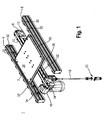
- the conveyor device 1 has a supporting device designed as a support plate 2.
- the support plate 2 is guided laterally between two parallel spaced guide rails 4 and 6 of a guideway and slidably mounted in a longitudinal direction of the guide rails 4 and 6 extending conveying direction.
- a traction means 8 is arranged for guiding and driving a traction means in the form of an annular tension band 10.
- This is formed circumferentially with a first and second reversal region 12 and 14, wherein in the second reversal region 14, a drive device 16 is arranged for the drawstring 10.
- This is in particular an electric motor, which is electrically contacted via power supply lines 18.
- the power supply 18 is connected via a plug connection 20 with a power supply, not shown.
- the drawstring 10 extends substantially in the conveying direction, ie along the guide rails 4 and 6 below the support plate 2. Between the reversal areas 12 and 14, the tension band 10 is stretched in the conveying direction. Via an inner band surface 22 of the tension band 10, the drive device 16 engages for driving the tension band 10. For this purpose, the inner band surface may have teeth, corresponding to a toothed belt into which a pinion of the drive device 16 then engages.
- the drawstring 10 is arranged such that an upper Buchbandabêt 24 adjacent to the support plate 2 is moved in the conveying direction and a lower Switzerlandbandabêt 26 is moved against the conveying direction.
- the drawstring 10 is magnetic, so it can be attracted by a magnetic force, and has for this purpose steel strands. These are circumferentially introduced into the drawstring 10 and enclosed with a plastic.
- the support plate 2 can be moved by the drawstring 10 in the conveying direction, this has on its side facing the tension band 10 side permanent magnets, which is explained in more detail in the following figures.
- the support plate 2 has an upper side 28, on which objects to be transported can be arranged. Furthermore, the support plate 2 is enclosed by a support frame 30, via which it is supported and guided on the guide rails 4 and 6.
- a respective guide rail 4 and 6 has a plurality of bearing rollers 32, of which, for the sake of simplicity, only some in the FIG. 2 are provided with a reference numeral. About the bearing rollers 32, the support plate 2 is guided laterally over its support frame 30 and slidably mounted in the conveying direction.
- a length of the guide rail 4 and 6 is in the FIG. 1 shown only as an example. These can be any length or consist of several, in particular composable, sections. The same applies to the Glasstoffani 8 and the Tieback 10, which may also have different lengths. It is conceivable to arrange a plurality of drawstrings one behind the other in series for long lengths, and / or to arrange one or more drawstrings parallel to one another. Also, a plurality of support plates 2 can be arranged on the conveyor device 1.
- the guide rail 4 has on its side facing away from the support plate 2 side also bearing rollers 32 which are arranged for a further parallel to the conveyor device 1 in the FIG. 1 serve not shown conveyor.
- the permanent magnets 34 can be seen. These are arranged in a magnet carrier housing 36, which is below in the FIGS. 7 and 8th is explained in more detail.
- a magnet carrier housing 36 On the support plate 2 in this case two magnetic carrier housing 36 and 38 are provided, which are arranged in the conveying direction in series one behind the other on a to the drawstring 10 facing bottom 40 of the support plate 2.
- the magnet carrier housing 36 and 38 extend substantially in the longitudinal direction of the conveying direction and above the Werbandabismes 24 of the tension band 10.
- a respective magnet carrier housing 36 and 38 with a bearing plate 42 is closed. This consists of a non-magnetic material, such as plastic.
- a respective bearing plate 42 forms on its underside a direction away from the permanent magnet 34 engagement surface 44 to which the drawstring 10 abuts with a holding portion of its outer wall surface 46 or slides along.
- a magnetic member in the form of a steel plate 48 is used to reinforce the magnetic force of the permanent magnets 34.
- a magnetic member in the form of a steel plate 48 is used to reinforce the magnetic force of the permanent magnets 34.
- four through holes 50 are introduced, via which the magnet carrier housing 36 and 38 are fixed by screws 52 on the support plate 2.
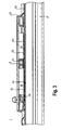
- FIG. 3 shows the support plate 2 with the cut support frame 30 and the magnet carrier housings 36 and 38.
- the drawstring 10 rests with its outer band surface 46 on the engagement surface 44 of a respective bearing plate 42 of a respective magnet carrier housing 36 and 38 at.
- the drawstring 10 is lifted in this area by a guide surface 54 of the tension member carrier 8, whereby a gap 56 is formed in the FIG. 3 is shown in black.
- the engagement surfaces 44 are thus of the outer band surface 46 of the tension band 10 approximately at a parallel distance, except for the part of the tension band, by the magnetic force of the permanent magnet 36 from FIG.
- the cross-section through the conveyor device 1 takes place through a plane that intersects the magnet carrier housing 36.
- the Buchstofftown 8 has in the FIG. 4 an inner support structure 58, which has an approximately U-shaped longitudinal recess 60 on its side facing the support plate 2, in which the circumferential drawstring 10 is arranged.
- the movable in the conveying direction Wegneckabites 24 extends here in a inserted into the longitudinal recess 60 of the support structure 58, a cross-sectionally U-shaped guide recess having, guide rail 62. This leads the Buchbandab mustard 24 of the drawstring 10 laterally and forms the guide surface 54, see also FIG. 3 , out.
- the support frame 30 of the support plate 2 has in each case on its side facing the guide rail 4 and 6 L-shaped bearing surfaces 64 and 66.
- a respective bearing surface 64 and 66 in this case has on a respective peripheral surface 68 of the bearing rollers 32 supporting support surface 70 and 72 and a lateral guide surface 76 and 78, respectively, which can be supported on a respective end face 74 of the bearing rollers 32.
- a respective bearing roller 32 is mounted on a bearing shaft 80 via a roller bearing 78, in particular a deep groove ball bearing, which are respectively fixed in the guide rails 4 and 6 stored.
- a respective guide rail 4 and 6 is configured in each case like a support structure.
- FIG. 5 shows a longitudinal section through the conveyor 1 in a plane which extends through the magnet carrier housing 36 and 38. Again, the drawstring 10 can be seen that in the area of the engagement surfaces 44 of the magnet carrier housing 36 and 38th lifts off from its guide surface 54. For better representation of the surfaces is an enlarged cross-section A of Figure 6 FIG. 5 shown.
- FIG. 6 is the guide strip 10 on the engagement surface 44 of the bearing plate 42 at.
- FIG. 6 is also a distance between the inner wall surface 22 of the bearing strip 10 and the guide surface 54 of the guide rail 62 from FIG. 4 recognizable.
- the permanent magnet 34 from FIG. 6 are circular cylindrical configured with an upper and lower end face 82 and 84. This lies with its lower end face 84 on an inner surface 86 of the bearing plate 42 at. On its upper end face 82 while the steel plate 48 is arranged.
- a distance from central axes 92 of the permanent magnets 34 is about 110 to 115% of a diameter of the permanent magnet 34.
- a distance between the engagement surface 44 of the bearing plate 42 and the outer band surface 46 of the fastener tape 10 is preferably between 0.5 to 2.5mm.
- the magnet carrier housing 36 in FIG. 7 has this total of 18 permanent magnets 34, which are arranged in a parallel array in two rows.
- the magnet carrier housing 36 made of aluminum has, for receiving each of the permanent magnets, a through hole 94 having an approximately circular cylindrical cross section into which a respective permanent magnet 34 can be inserted and stored via its outer circumferential surface.
- the arrangement of the through holes 94, a distance between the permanent magnet 34 is determined, which is explained above. This distance also applies to the permanent magnets 34 arranged in series with one another.
- the through-bores 94 of the magnet carrier housing 36 are introduced into a bottom side 96 of the approximately cup-shaped magnet carrier housing 36.
- the pot shape is created by an inserted into the magnet carrier housing 36 longitudinal groove 98.
- This has two oppositely spaced side surfaces 100 and 102, between which the through holes 94 are formed.
- the longitudinal groove 98 is in the region of their respective Widened end portion 104 and 106 in the transverse direction, in which in a respective side surface 100 and 102 end a semi-circular cross-section having recess is introduced.
- the steel plate 48 has a longitudinal groove 98 corresponding length and a distance of the side surfaces 102 and 104 of the longitudinal groove 98 corresponding width whereby it is laterally supported in the longitudinal groove 98 through the magnet carrier housing 36.
- I the top 88 of the stave plate 48 are two blind holes 108 introduced, in each of which a pin 110 is inserted.
- An end face 111 of a respective pin 110 facing away from the upper side 88 lies approximately in one plane with a support plate 2 FIG. 2 facing top 113 of the magnet carrier housing 36, whereby the steel plate 48 via the pins 110 from the bottom 90 of the support plate 2 against the bottom side 96 and / or against the permanent magnet 34 of the magnet carrier housing 36 can be tensioned.
- the steel plate 48 can be gripped laterally by a fitter or a machine through the longitudinal groove 98, which is widened in the transverse direction at the end, in a state inserted into the magnet carrier housing 36.
- two bores 114 are respectively introduced, via which the magnet carrier housing 36 with the screws 52 FIG. 2 is determined on the support plate 2.
- the permanent magnets 34 are disposed in the magnet carrier housing 36 so that their poles are alternately aligned.
- the poles of the permanent magnets 34 are in the FIG. 7 denoted by the reference symbol S for the south pole and the reference symbol N for the north pole.
- the respectively immediately adjacent permanent magnets are arranged in the reverse polarity direction in the magnet carrier housing 36.
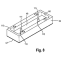
- FIG. 8 shows the magnet carrier housing 36 in the assembled state.
- the arrangement of the end faces 111 of the pins 110 and the upper side 113 of the magnet support housing 36 can be seen in an approximately same plane.
- the permanent magnets 34 out FIG. 7 are thus mounted between the bearing plate 42 and the steel plate 48 in the magnet carrier housing 36, wherein the steel plate 48 in turn via their pins 110 of the support plate 3 from FIG. 2 and is defined by the longitudinal groove 98 in the magnet carrier housing 36.
- the tension band 10 slides with its outer band surface 46 out FIG. 2 at the engagement surfaces 44 of the support plate 2, wherein the support plate 2 is then accelerated by a frictional force. From a certain speed of the support plate 2, the outer band surface 46 and the engagement surface 44 of the support plate 2 adhere to each other again.
- the maximum transferable to the support plate 2 tensile force is advantageously independent of their weight and thus independent of their payload, since the weight of the support plate 2 is supported by the guide rails 4 and 6.
- the transferable to the support plate 2 of the drawstring 10 traction is dependent on the size of the magnetic force.
- the magnetic force acting on the drawstring can be determined by the number of permanent magnets 34 FIG. 7 be set.
- the permanent magnet 34 from FIG. 7 For example, have a diameter of 10mm and exist from NdFeB.
- An adhesion force is about 2.4 kg directly at the magnet, about 1.0 kg at a distance of 1 mm and about 0.5 kg at a distance of 2 mm.
- a holding force between the drawstring 10 and the support plate 2 is preferably 10 N.
- the transferable from the drawstring 10 on the support plate 2 tensile force can also by the coefficient of friction between the outer band surface 46 and the engagement surface 44, see FIG. 3 to be discontinued. It has been shown that a friction coefficient ⁇ is approximately between 0.3 to 0.5, wherein the outer band surface 46 and the engagement surface 44 are preferably flat. It is also conceivable, however, that these surfaces have teeth that intermesh positively in order to increase the coefficient of friction.
- a conveying device for moving a support plate with a traction means in the form of a tension band.
- the tension band is brought by a magnetic force of at least one permanent magnet in contact with this, whereby the support plate is then moved over the tension band due to static friction or sliding friction.
Landscapes
- Engineering & Computer Science (AREA)
- Mechanical Engineering (AREA)
- Non-Mechanical Conveyors (AREA)
- Structure Of Belt Conveyors (AREA)
- Belt Conveyors (AREA)
Description
- Die Erfindung betrifft eine Fördervorrichtung gemäß dem Oberbegriff des Patentanspruchs 1.
- In der
GB 1 350 715 - Nachteilig bei dieser Lösung ist die vorrichtungstechnisch äußerst aufwendige Ausgestaltung der Fördervorrichtung.
- Aus der
DE 195 38 350 A1 ist eine Fördervorrichtung in Form eines Hängefördersystems bekannt. Die Tragvorrichtung ist gleitend in einer Profilschiene geführt, wobei das Tansportgut bezüglich der Richtung der Schwerkraft unterhalb der Profilschiene angeordnet ist. Oberhalb der Tragvorrichtung befindet sich ein Zugmittel in Form eines Transportbandes, das aus magnetisierbarem Material besteht. In der Tragvorrichtung befinden sich Permanentmagnete, welche die Tragvorrichtung mit dem Zugmittel verbinden können. Die Permanentmagenete sind in einem Magnetträgergehäuse angeordnet. Nachteilig ist, dass die Permanentmagnete das Zugmittel unmittelbar berühren. Hierdurch kann es zu Abrieb und Beschädigungen an den Permanentmagneten kommen, wenn Schlupf zwischen dem Zugmittel und der Tragvorrichtung auftritt. Dies ist beispielsweise der Fall, wenn die Tragvorrichtung an einer gewünschten Position stillgesetzt wird, wobei das Zugmittel weiterläuft. Dieser Nachteil wird durch die Erfindung überwunden. - Aus der
DD 228 790 A1 WO 2008/064834 A2 und derDE 42 10 188 A1 sind weitere Fördervorrichtungen bekannt, welche Magnete umfassen. - Weiter liegt der Erfindung die Aufgabe zugrunde eine vorrichtungstechnisch einfach aufgebaute Fördervorrichtung zu schaffen.
- Diese Aufgabe wird gelöst mit den Merkmalen des Patentanspruchs 1.
- Sonstige vorteilhafte Weiterbildungen der Erfindung sind Gegenstand weiterer Unteransprüche.
- Erfindungsgemäß hat eine Fördervorrichtung eine zum transportieren eingesetzte Tragvorrichtung, insbesondere eine Trägerplatte. Diese ist über eine Führungsbahn verschiebbar in zumindest einer Förderrichtung gelagert und geführt. Zum Bewegen der Tragvorrichtung ist ein, sich insbesondere in Förderrichtung erstreckendes, Zugmittel angeordnet. Zum Verbinden der Tragvorrichtung mit dem Zugmittel, um eine Zugkraft vom Zugmittel auf die Tragvorrichtung zu übertragen, ist eine Magnetkraft eines Permanentmagneten vorgesehen.
- Diese Lösung hat den Vorteil, dass die Verbindung der Tragvorrichtung mit dem Zugmittel mit einem geringen vorrichtungstechnischen Aufwand einfach mit einem Permanentmagneten erfolgt. Es sind insbesondere keine vorrichtungstechnisch aufwendig ausgestaltete Stromzuführungen, wie im eingangs erläuterten Stand der Technik, notwendig.
- Vorzugsweise ist der Permanentmagnet an der Tragvorrichtung angeordnet. Somit ist denkbar, dass für unterschiedliche Tragvorrichtungen, das heißt Tragvorrichtungen mit unterschiedlichem Gewicht, unterschiedliche starke Permanentmagneten eingesetzt werden können und das Zugmittel nicht an die Tragvorrichtung angepasst werden muss.
- In weiterer Ausgestaltung ist das Zugmittel ein, insbesondere umlaufendes, Zugband. Dieses kann sich dann entlang der Führungsbahn erstrecken, wodurch die Tragvorrichtung an einer beliebigen Stelle der Führungsbahn in Förderrichtung gesehen mit dem Zugband verbindbar ist. Denkbar wäre auch eine Mehrzahl von parallel oder in Reihe angeordneter Zugbänder einzusetzen.
- Das Zugband besteht vorzugsweise aus einem magnetischen Material. Insbesondere weist es etwa in Förderrichtung sich erstreckende Stahllitzen auf, die in einem Kunststoff eingebettet sind.
- In weiterer Ausgestaltung der Erfindung hat das Zugband eine Außenwandfläche, die an eine Angriffsfläche der Tragvorrichtung anlegbar ist. Über die Angriffsfläche wirkt dann die Magnetkraft des Permanentmagneten auf das Zugband. Eine derartige Anordnung erlaubt es, dass die Tragvorrichtung und das Zugband über die genannten Flächen aneinander haften oder relativ zueinander gleiten. Somit kann das Zugband die Tragevorrichtung auch dann in Förderrichtung aufgrund von Reibkräften antreiben, wenn die Außenbandfläche und die Angriffsfläche aufeinander abgleiten.
- Mit Vorteil sind die Außenwandfläche des Zugbands und die Angriffsfläche der Tragvorrichtung derart ausgestaltet, dass diese bei Überschreiten einer vorbestimmten auf die Tragvorrichtung wirkenden Zugkraft aufeinander gleiten. Somit wird die auf die Tragvorrichtung durch das Zugband in Förderrichtung wirkende Beschleunigung begrenzt, wodurch beispielsweise ein sanftes Anfahren der Tragvorrichtung aus einem Stillstand möglich ist. Wird eine oder mehrere Tragvorrichtungen an einer Bewegung in Förderrichtung gehindert, beispielsweise weil sie das Ende der Fördervorrichtung erreicht haben (Staubetrieb), so kann das Zugband einfach unter der einen oder der Mehrzahl von Tragvorrichtungen entlang gleiten. Ein Verschleiß des Zugbands ist hierbei vorteilhafterweise äußerst gering. Des Weiteren ist eine Antriebsleistung eines Antriebs für das Zugband ebenfalls sehr gering, da die auf die Tragvorrichtung wirkende Zugkraft durch die Gleitmöglichkeit zwischen Tragvorrichtung und Zugband begrenzt ist.
- Vorzugsweise beträgt eine Haltekraft zwischen der Außenwandfläche des Zugbands und der Angriffsfläche der Tragvorrichtung in Förderrichtung etwa maximal 10 N.
- Es ist ein Magnetträgergehäuse an der Tragvorrichtung zum Lagern und Festlegen des zumindest einen Permanentmagneten angeordnet. Dieses besteht insbesondere aus einem nichtmagnetischen Material, wie beispielsweise Aluminium. Die Angriffsfläche der Tragvorrichtung kann dann am Magnetträgergehäuse ausgebildet sein.
- Das Magnetträgergehäuse ist von einer nichtmagnetischen Lagerplatte begrenzt, wobei zumindest ein Abschnitt einer Außenfläche der Lagerplatte die Angriffsfläche bildet. Die Permanentmagneten können sich dann an einer Innenfläche der Lagerplatte abstützen. Hierdurch kann ein Abstand zwischen dem zumindest einen Permanentmagneten und dem Zugband durch eine Dicke der Lagerplatte eingestellt werden. Die Lagerplatte besteht insbesondere aus einem Kunststoff.
- Sind eine Mehrzahl von Permanentmagneten vorgesehen, so können diese vorzugsweise matrixartig im Magnetträgergehäuse mit wechselweiser Polung angeordnet werden. Die Permanentmagneten weisen insbesondere einen kreiszylindrischen Querschnitt auf und liegen mit ihrer Stirnfläche auf der Innenfläche der Tragplatte. Zur Verstärkung der Magnetkraft eines oder mehrerer Permanentmagneten kann in das Magnetträgergehäuse zusätzlich ein magnetisches Element, wie beispielsweise eine Stahlplatte, eingesetzt werden.
- In weiterer Ausgestaltung der Erfindung ist die Tragvorrichtung von der Führungsbahn relativ zum Zugband derart gelagert und geführt, dass ein an der Angriffsfläche der Tragvorrichtung anliegender Halteabschnitt des Zugbands von einer Führungsebene des Zugbands beabstandet ist. Das Zugband wird somit insbesondere im Bereich der Angriffsfläche etwa in Richtung einer Flächennormalen ihrer Außenwandfläche hin zur Tragvorrichtung versetzt. Dies hat den Vorteil, dass eine Innenmantelfläche des Zugbands, über die das Zugband geführt sein kann, von einer Zugbandführung im Bereich ihres Halteabschnitts beabstandet ist, wodurch eine Reibung zwischen dem Zugband und der Zugbandführung verkleinert ist. Sind mehrere Tragvorrichtungen vorgesehen, so sind entsprechend mehrere Halteabschnitte des Zugbands zur Führungsebene des Zugbands versetzt, wodurch eine Reibung zwischen der Innenmantelfläche des Zugbands und einer Führungsfläche weiter stark gesenkt wird.
- Bevorzugter Weise beträgt ein Haftreibwert zwischen der Angriffsfläche der Tragvorrichtung und der Außenfläche des Zugbands zwischen 0,3 bis 0,5. Die Angriffsfläche der Tragvorrichtung und die Außenwandfläche des Zugbands sind hier im Wesentlichen eben ausgebildet. Denkbar wäre allerdings auch, dass diese Flächen eine Verzahnung aufweisen.
- Vorteilhafterweise ist ein Abstand zwischen der Angriffsfläche und der Außenwandfläche im magnetfreien Zustand etwa 0,5 bis 2,0mm, wobei eine Dicke der Tragplatte 1 mm betragen kann.
- Zur Führung der Tragvorrichtung hat die Führungsbahn zumindest zwei im Wesentlichen im Parallelabstand zueinander angeordneter Führungsschienen. Zwischen denen kann dann die Tragvorrichtung etwa quer zur Förderrichtung geführt sein und in Förderrichtung gleitend gelagert werden.
- Um eine Lagerreibung zu minimieren, können an der Führungsbahn und / oder an der Tragvorrichtung Lagerrollen zum Führen und Lagern der Tragvorrichtung vorgesehen sein.
- Zum Führen und Lagern des Zugmittels ist vorzugsweise ein Zugmittelträger vorgesehen, an dem auch ein Zugmittelantrieb angeordnet sein kann.
- Im Folgenden wird anhand schematischer Zeichnungen ein bevorzugtes Ausführungsbeispiel der Erfindung näher erläutert. Es zeigen:
-
Figur 1 in einer perspektivischen Darstellung die erfindungsgemäße Fördervorrichtung gemäß einem Ausführungsbeispiels; -
Figur 2 in einer Explosionsdarstellung einen Teil der erfindungsgemäßen Fördervorrichtung; -
Figur 3 in einer Längsschnittansicht einen Ausschnitt der erfindungsgemäßen Fördervorrichtung; -
Figur 4 in einer Querschnittansicht die erfindungsgemäße Fördervorrichtung; -
Figur 5 eine weitere Längsschnittansicht eines Ausschnitts der erfindungsgemäßen Fördervorrichtung; -
Figur 6 einen vergrößerten Ausschnitt A der Fördervorrichtung ausFigur 5 ; -
Figur 7 in einer Explosionsdarstellung ein Magnetträgergehäuse der erfindungsgemäßen Fördervorrichtung, und -
Figur 8 in einer perspektivischen Darstellung das Magnetträgergehäuse. - Gemäß
Figur 1 hat die Fördervorrichtung 1 eine als Tragplatte 2 ausgebildete Tragvorrichtung. Die Tragplatte 2 ist zwischen zwei im Parallelabstand angeordneter Führungsschienen 4 und 6 einer Führungsbahn seitlich geführt und in einer sich in Längsrichtung der Führungsschienen 4 und 6 sich erstreckenden Förderrichtung verschiebbar gelagert. Etwa mittig zwischen den Führungsschienen 4 und 6 ist ein Zugmittelträger 8 zum Führen und Antreiben eines Zugmittels in Form eines ringförmigen Zugbands 10 angeordnet. Dieses ist umlaufend ausgebildet mit einem ersten und zweiten Umkehrbereich 12 und 14, wobei im zweiten Umkehrbereich 14 eine Antriebsvorrichtung 16 für das Zugband 10 angeordnet ist. Bei dieser handelt es sich insbesondere um einen Elektromotor, der über Stromzuführungen 18 elektrisch kontaktiert ist. Die Stromzuführung 18 ist über eine Steckerverbindung 20 mit einer nicht dargestellten Stromzuführung verbindbar. - Das Zugband 10 erstreckt sich im Wesentlichen in Förderrichtung, also entlang der Führungsschienen 4 und 6 unterhalb der Tragplatte 2. Zwischen den Umkehrbereichen 12 und 14 ist das Zugband 10 in Förderrichtung gespannt. Über eine Innenbandfläche 22 des Zugbands 10 greift die Antriebsvorrichtung 16 zum Antreiben des Zugbands 10 an. Hierzu kann die Innenbandfläche Zähne aufweisen, entsprechend einem Zahnriemen, in die dann ein Ritzel der Antriebsvorrichtung 16 eingreift. Das Zugband 10 ist dabei derart angeordnet, dass ein oberer Zugbandabschnitt 24 benachbart zur Tragplatte 2 in Förderrichtung bewegt ist und ein unterer Zugbandabschnitt 26 gegen die Förderrichtung bewegt ist. Das Zugband 10 ist magnetisch, kann also von einer Magnetkraft angezogen werden, und weist hierzu Stahllitzen auf. Diese sind umlaufend in das Zugband 10 eingebracht und mit einem Kunststoff umschlossen.
- Damit die Tragplatte 2 vom Zugband 10 in die Förderrichtung bewegt werden kann, weist diese auf ihrer zum Zugband 10 weisenden Seite Permanentmagneten auf, was in den nachfolgenden Figuren näher erläutert ist.
- Die Tragplatte 2 hat eine Oberseite 28, auf die zu transportierende Gegenstände angeordnet werden können. Des Weiteren ist die Tragplatte 2 von einem Tragrahmen 30 eingefasst, über den diese auf den Führungsschienen 4 und 6 gelagert und geführt ist. Eine jeweilige Führungsschiene 4 und 6 weist eine Vielzahl von Lagerrollen 32 auf, von denen der Einfachheit halber nur einige in der
Figur 2 mit einem Bezugszeichen versehen sind. Über die Lagerrollen 32 ist die Tragplatte 2 über ihren Tragrahmen 30 seitlich geführt und in Förderrichtung verschiebbar gelagert. - Eine Länge der Führungsschiene 4 und 6 ist in der
Figur 1 nur beispielhaft dargestellt. Diese können dabei beliebig lang sein oder aus mehreren, insbesondere zusammensetzbaren, Abschnitten bestehen. Das gleiche gilt für den Zugmittelträger 8 und das Zugband 10, die auch unterschiedliche Längen aufweisen können. Es ist denkbar, mehrere Zugbänder hintereinander in Reihe für große Längen anzuordnen, und/oder ein oder mehrere Zugbänder parallel zueinander anzuordnen. Auch kann eine Mehrzahl von Tragplatten 2 auf der Fördervorrichtung 1 angeordnet werden. Die Führungsschiene 4 hat auf ihrer von der Tragplatte 2 wegweisenden Seite ebenfalls Lagerrollen 32, die für eine weitere parallel zur Fördervorrichtung 1 angeordnete in derFigur 1 nicht dargestellte Fördervorrichtung dienen. - In der
Figur 2 sind die Permanentmagneten 34 ersichtlich. Diese sind in einem Magnetträgergehäuse 36 angeordnet, was unten stehenden in denFiguren 7 und8 näher erläutert ist. An der Tragplatte 2 sind hierbei zwei Magnetträgergehäuse 36 und 38 vorgesehen, die in Förderrichtung gesehen in Reihe hintereinander an einer zum Zugband 10 weisenden Unterseite 40 der Tragplatte 2 angeordnet sind. Die Magnetträgergehäuse 36 und 38 erstrecken sich im Wesentlichen in Längsrichtung der Förderrichtung und oberhalb des Zugbandabschnitts 24 des Zugbands 10. Bodenseitig ist ein jeweiliges Magnetträgergehäuse 36 und 38 mit einer Lagerplatte 42 verschlossen. Diese besteht aus einem nichtmagnetischen Material, beispielsweise Kunststoff. Eine jeweilige Lagerplatte 42 bildet an ihrer Unterseite eine von den Permanentmagneten 34 wegweisende Angriffsfläche 44 aus, an die das Zugband 10 mit einem Halteabschnitt seiner Außenwandfläche 46 anliegt oder entlang gleitet. - In ein jeweiliges Magnetträgergehäuse 36 und 38 ist zusätzlich zu den Permanentmagneten 34 ein magnetisches Element in Form einer Stahlplatte 48 eingesetzt, um die Magnetkraft der Permanentmagneten 34 zu verstärken. In der Tragplatte 2 sind für ein jeweiliges Magnetträgergehäuse 36 und 38 vier Durchgangsbohrungen 50 eingebracht, über die die Magnetträgergehäuse 36 und 38 durch Schrauben 52 an der Tragplatte 2 festgelegt sind.
- Der Längsschnitt gemäß
Figur 3 durch die Fördervorrichtung 1 erfolgt in einer die Fördervorrichtung 1 etwa zwischen dem Zugmittelträger 8 und der rechten Führungsschiene 6 ausFigur 1 schneidenden Ebene.Figur 3 zeigt die Tragplatte 2 mit dem geschnittenen Tragrahmen 30 und den Magnetträgergehäusen 36 und 38. Das Zugband 10 liegt dabei mit seiner Außenbandfläche 46 an der Angriffsfläche 44 einer jeweiligen Lagerplatte 42 eines jeweiligen Magnetträgergehäuses 36 beziehungsweise 38 an. Das Zugband 10 wird dabei in diesem Bereich von einer Führungsfläche 54 des Zugmittelträgers 8 abgehoben, wodurch ein Spalt 56 entsteht, der in derFigur 3 schwarz dargestellt ist. Die Angriffsflächen 44 sind somit von der Außenbandfläche 46 des Zugbands 10 etwa im Parallelabstand, außer zu dem Teil des Zugbands, der durch die Magnetkraft der Permanentmagneten 36 ausFigur 2 an der Angriffsfläche 44 anliegt. Sind mehrere Tragplatten 2 bei der Fördervorrichtung 2 vorgesehen, so wird das Zugband 10 auch von den weiteren Tragplatten 2 durch die Magnetkraft von der Führungsfläche 54 des Zugmittelsträger 8 angehoben, wodurch eine Reibung zwischen der Führungsfläche 54 und dem Zugband 10 insgesamt stark verringert ist. - Gemäß der
Figur 4 erfolgt der Querschnitt durch die Fördervorrichtung 1 durch eine Ebene, die das Magnetträgergehäuse 36 schneidet. Der Zugmittelträger 8 hat in derFigur 4 eine innere Tragstruktur 58, die auf ihrer zur Tragplatte 2 weisenden Seite eine etwa U-förmige Längsaussparung 60 aufweist, in der das umlaufende Zugband 10 angeordnet ist. Der in Förderungsrichtung bewegbare Zugbandabschnitt 24 erstreckt sich hierbei in einer in die Längsaussparung 60 der Tragstruktur 58 eingesetzten, eine im Querschnitt U-förmige Führungsaussparung aufweisende, Führungsschiene 62. Diese führt den Zugbandabschnitt 24 des Zugbands 10 seitlich und bildet die Führungsfläche 54, siehe auchFigur 3 , aus. Auf der von der Tragplatte 2 weg weisenden Seite der Führungsschiene 62 ist der sich gegen die Förderrichtung bewegende Zugbandabschnitt 26 über geeignete Mittel in dem Zugmittelträger 8 geführt. - Der Tragrahmen 30 der Tragplatte 2 hat jeweils auf seiner zur Führungsschiene 4 bzw. 6 weisenden Seite L-förmig ausgestaltete Lagerflächen 64 bzw. 66. Eine jeweilige Lagerfläche 64 und 66 hat hierbei eine sich auf einer jeweiligen Umfangsfläche 68 der Lagerrollen 32 abstützende Stützfläche 70 bzw. 72 und eine sich an einer jeweiligen Stirnfläche 74 der Lagerrollen 32 abstützbare Seitenführungsfläche 76 bzw. 78. Eine jeweilige Lagerrolle 32 ist über ein Wälzlager 78, insbesondere ein Rillenkugellager, auf einer Lagerachse 80, die jeweils in den Führungsschienen 4 bzw. 6 festgelegt sind gelagert. Eine jeweilige Führungsschiene 4 und 6 ist jeweils tragstrukturartig ausgestaltet.
-
Figur 5 zeigt einen Längsschnitt durch die Fördervorrichtung 1 in einer Ebene, die sich durch die Magnetträgergehäuse 36 und 38 erstreckt. Auch hier ist das Zugband 10 erkennbar, das im Bereich der Angriffsflächen 44 der Magnetträgergehäuse 36 bzw. 38 von ihrer Führungsfläche 54 abhebt. Zur besseren Darstellbarkeit der Flächen ist in Figur 6 ein vergrößerter Querschnitt A derFigur 5 gezeigt. - Gemäß
Figur 6 liegt das Führungsband 10 an der Angriffsfläche 44 der Lagerplatte 42 an. In dieserFigur 6 ist auch ein Abstand zwischen der Innenwandfläche 22 des Lagerbands 10 und der Führungsfläche 54 der Führungsschiene 62 ausFigur 4 erkennbar. Die Permanentmagneten 34 ausFigur 6 sind kreiszylindrisch ausgestaltet mit einer oberen und unteren Stirnfläche 82 bzw. 84. Diese liegt mit ihrer unteren Stirnfläche 84 an einer Innenfläche 86 der Lagerplatte 42 an. Auf ihrer oberen Stirnfläche 82 ist dabei die Stahlplatte 48 angeordnet. Zwischen einer von den Permanentmagneten 34 weg weisenden Oberseite 88 der Stahlplatte 48 und einer zur Stahlplatte 48 weisenden Unterseite 90 der Tragplatte 2 ist ein Freiraum, damit Magnetkräfte im Bereich der Oberseite 28 der Tragplatte 2 möglichst gering sind, um darauf angeordnete zu transportierende Gegenstände möglichst nicht mit Magnetkräften zu beeinflussen. - Ein Abstand von Mittelachsen 92 der Permanentmagneten 34 beträgt etwa 110 bis 115 % eines Durchmessers des Permanentmagneten 34. Ein Abstand zwischen der Angriffsfläche 44 der Lagerplatte 42 und der Außenbandfläche 46 des Tragbands 10 beträgt vorzugsweise zwischen 0,5 bis 2,5mm.
- Gemäß der Explosionsdarstellung des Magnetträgergehäuses 36 in
Figur 7 weist dieses insgesamt 18 Permanentmagneten 34 auf, die parallel in zwei Reihen matrixartig angeordnet sind. Das aus Aluminium bestehende Magnetträgergehäuse 36 weist zur Aufnahme eines jeden Permanentmagneten eine einen etwa kreiszylindrischen Querschnitt aufweisende Durchgangsbohrung 94 auf, in die ein jeweiliger Permanentmagnet 34 einsetzbar und über seine Außenmantelfläche lagerbar ist. Durch die Anordnung der Durchgangsbohrungen 94 wird ein Abstand zwischen den Permanentmagneten 34 bestimmt, der oben stehend erläutert ist. Dieser Abstand gilt auch für die zueinander in Reihe angeordneten Permanentmagneten 34. Die Durchgangsbohrungen 94 des Magnetträgergehäuses 36 sind in eine Bodenseite 96 des etwa topfförmig ausgebildeten Magnetträgergehäuses 36 eingebracht. Die Topfform wird durch eine in das Magnetträgergehäuse 36 eingebrachte Längsnut 98 geschaffen. Diese hat zwei sich gegenüber im Parallelabstand angeordnete Seitenflächen 100 und 102, zwischen denen die Durchgangsbohrungen 94 ausgebildet sind. Die Längsnut 98 ist im Bereich ihres jeweiligen Endabschnitts 104 bzw. 106 in Querrichtung verbreitert, in dem in eine jeweilige Seitenfläche 100 und 102 endseitig eine einen halbkreisförmigen Querschnitt aufweisende Aussparung eingebracht ist. - Die Stahlplatte 48 hat eine der Längsnut 98 entsprechende Länge und eine dem Abstand der Seitenflächen 102 und 104 der Längsnut 98 entsprechende Breite wodurch diese in der Längsnut 98 durch das Magnetträgergehäuse 36 seitlich gelagert ist. I die Oberseite 88 der Stehlplatte 48 sind zwei Sacklochbohrungen 108 eingebracht, in die jeweils ein Stift 110 eingesetzt ist. Eine von der Oberseite 88 weg weisende Stirnfläche 111 eines jeweiligen Stifts 110 liegt dabei etwa in einer Ebene mit einer zur Tragplatte 2 aus
Figur 2 weisenden Oberseite 113 des Magnetträgergehäuses 36, wodurch die Stahlplatte 48 über die Stifte 110 von der Unterseite 90 der Tragplatte 2 gegen die Bodenseite 96 und/ oder gegen die Permanentmagneten 34 des Magnetträgergehäuses 36 spannbar ist. - Durch die endseitig in Querrichtung verbreiterte Längsnut 98 kann die Stahlplatte 48 in einem in das Magnetträgergehäuse 36 eingesetzten Zustand seitlich von einem Monteur oder einer Maschine gegriffen werden.
- Zwischen einer jeweiligen Seitenfläche 100 und 102 und einer Außenmantelfläche 112 des Magnetträgergehäuses 36 sind jeweils zwei Bohrungen 114 eingebracht, über die das Magnetträgergehäuse 36 mit den Schrauben 52 aus
Figur 2 an der Tragplatte 2 festgelegt wird. - Die Permanentmagneten 34 sind derart in dem Magnetträgergehäuse 36 angeordnet, dass ihre Pole wechselweise ausgerichtet sind. Die Pole der Permanentmagneten 34 sind in der
Figur 7 durch das Bezugszeichen S für Südpol und Bezugszeichen N für Nordpol gekennzeichnet. Ausgehend von einem jeweiligen Permanentmagneten 34 sind die jeweils unmittelbar benachbarten Permanentmagneten in umgekehrter Polrichtung in dem Magnetträgergehäuse 36 angeordnet. -
Figur 8 zeigt das Magnetträgergehäuse 36 in zusammengesetzten Zustand. Hierbei ist die Anordnung der Stirnflächen 111 der Stifte 110 und der Oberseite 113 des Magnetträgegehäuses 36 in einer etwa gleichen Ebene ersichtlich. Die Permanentmagneten 34 ausFigur 7 werden somit zwischen der Lagerplatte 42 und der Stahlplatte 48 im Magnetträgergehäuse 36 gelagert, wobei die Stahlplatte 48 wiederum über ihre Stifte 110 von der Tragplatte 3 ausFigur 2 und durch die Längsnut 98 im Magnetträgergehäuse 36 festgelegt ist. - Im Folgenden wird die Funktionsweise der Fördervorrichtung 1 anhand der
Figuren 1 bis 8 näher erläutert. - Im Einsatz der Fördervorrichtung 1 führt das Zugband aus
Figur 1 eine umlaufende Bewegung aus, wobei sich der benachbart zur Tragplatte 2 befindliche Zugbandabschnitt 24 in Förderrichtung bewegt. Wird nun die Tragplatte 2 auf die Führungsschienen 4 und 6 gesetzt, so wird das Zugband 10 durch die Permanentmagneten 34, sieheFigur 5 und6 , durch die Magnetkraft auf die Angriffsfläche 44 der Lagerplatte 42 gezogen. Das Zugband 10 hebt dann in diesem Bereich von ihrer Führungsfläche 54 ab, wodurch sich ein Spalt bildet. Haftet nun das Zugband 10 an der Angriffsfläche 44 der Tragplatte 2, so wird die Tragplatte 2 durch eine von der Antriebsvorrichtung 16 ausFigur 1 erzeugte Zugkraft des Zugbands 10 beschleunigt. Übersteigt die auf die Tragplatte 2 wirkende Zugkraft einen vorbestimmten Wert, so gleitet das Zugband 10 mit ihrer Außenbandfläche 46 ausFigur 2 an den Angriffsflächen 44 der Tragplatte 2 ab, wobei die Tragplatte 2 dann über eine Reibungskraft beschleunigt wird. Ab einer bestimmten Geschwindigkeit der Tragplatte 2 haften die Außenbandfläche 46 und die Angriffsfläche 44 der Tragplatte 2 wieder aufeinander. Die maximale auf die Tragplatte 2 übertragbare Zugkraft ist dabei vorteilhafterweise unabhängig von deren Gewicht und somit unabhängig von deren Zuladung, da das Gewicht der Tragplatte 2 durch die Führungsschienen 4 und 6 getragen wird. - Die auf die Tragplatte 2 von dem Zugband 10 übertragbare Zugkraft ist dabei abhängig von der Größe der Magnetkraft. Je größer die Magnetkraft, desto größer ist auch die auf die Tragplatte 2 übertragbare Zugkraft. Die auf das Zugband wirkende Magnetkraft kann durch die Anzahl der Permanentmagneten 34 aus
Figur 7 eingestellt werden. Je mehr Permanentmagneten 34 vorgesehen sind, desto größer ist die auf das Zugband 10 wirkende Magnetkraft. Durch Veränderung der Anzahl von Permanentmagneten 34 kann somit eine Anpassung an ein Werkstückgewicht erfolgen. Die Permanentmagneten 34 ausFigur 7 haben beispielsweise einen Durchmesser von 10mm und bestehen aus NdFeB. Eine Haftkraft beträgt unmittelbar am Magneten etwa 2,4 kg, bei einem Abstand von 1 mm etwa 1,0 kg und bei einem Abstand von 2mm etwa 0,5 kg. - Eine Haltekraft zwischen dem Zugband 10 und der Tragplatte 2 beträgt vorzugsweise 10 N.
- Die von dem Zugband 10 auf die Tragplatte 2 übertragbare Zugkraft kann auch durch den Reibwert zwischen der Außenbandfläche 46 und der Angriffsfläche 44, siehe
Figur 3 , eingestellt werden. Es hat sich gezeigt, dass ein Reibungskoeffizient µ etwa zwischen 0,3 bis 0,5 beträgt, wobei die Außenbandfläche 46 und die Angriffsfläche 44 vorzugsweise eben ausgebildet sind. Denkbar ist allerdings auch, dass diese Fläche Verzahnungen aufweisen, die formschlüssig ineinander greifen, um den Reibwert zu erhöhen. - Offenbart ist eine Fördervorrichtung zum Bewegen einer Tragplatte mit einem Zugmittel in Form eines Zugbands. Zum Ziehen der Tragplatte wird das Zugband über eine Magnetkraft zumindest eines Permanentmagneten in Anlage an diese gebracht, wodurch die Tragplatte dann über das Zugband aufgrund von Haftreibung oder Gleitreibung mitbewegt wird.
-
- 1
- Fördervorrichtung
- 2
- Tragplatte
- 4
- Führungsschiene
- 6
- Führungsschiene
- 8
- Zugmittelträger
- 10
- Zugband
- 12
- Umkehrbereich
- 14
- Umkehrbereich
- 16
- Antriebsvorrichtung
- 18
- Stromzuführung
- 20
- Steckerverbindung
- 22
- Innenbandfläche
- 24
- Zugbandabschnitt
- 26
- Zugbandabschnitt
- 28
- Oberseite
- 30
- Tragrahmen
- 32
- Lagerrolle
- 34
- Permanentmagnet
- 36
- Magnetträgergehäuse
- 38
- Magnetträgergehäuse
- 40
- Unterseite
- 42
- Lagerplatte
- 44
- Angriffsfläche
- 46
- Außenbandfläche
- 48
- Stahlplatte
- 50
- Durchgangsbohrung
- 52
- Schraube
- 54
- Führungsfläche
- 56
- Spalt
- 58
- Tragstruktur
- 60
- Längsaussparung
- 62
- Führrungsschiene
- 64
- Lagerfläche
- 66
- Lagerfläche
- 68
- Umfangsfläche
- 70
- Stützfläche
- 72
- Stützfläche
- 74
- Stirnfläche
- 76
- Seitenführungsfläche
- 78
- Wälzlager
- 80
- Lagerachse
- 82
- Stirnfläche
- 84
- Stirnfläche
- 86
- Innenfläche
- 88
- Oberseite
- 90
- Unterseite
- 92
- Mittelachsen
- 94
- Durchgangsbohrung
- 96
- Bodenseite
- 98
- Längsnut
- 100
- Seitenfläche
- 102
- Seitenfläche
- 104
- Endabschnitt
- 106
- Endabschnitt
- 108
- Sacklochbohrung
- 110
- Stift
- 111
- Stirnfläche
- 112
- Außenmantelfläche
- 113
- Oberseite
- 114
- Bohrung
Claims (13)
- Fördervorrichtung mit einer Tragvorrichtung (2), die über eine Führungsbahn (4, 6) verschiebbar in einer Förderrichtung gelagert und geführt ist, wobei ein Zugmittel (10) zum Ziehen der Tragvorrichtung in die Förderrichtung angeordnet ist, wobei zum Verbinden der Tragvorrichtung (2) mit dem Zugmittel (10) eine Magnetkraft eines Permanentmagneten (34) vorgesehen ist, wobei ein Magnetträgergehäuse (36, 38) an der Tragvorrichtung (2) zum Lagern und Festlegen des zumindest einen Permanentmagneten (34) angeordnet ist,
dadurch gekennzeichnet, dass das Magnetträgergehäuse (36, 38)
von einer nicht magnetischen Lagerplatte (42) begrenzt ist, wobei zumindest ein Abschnitt einer Außenfläche der Lagerplatte (42) die Angriffsfläche (44) bildet, und
wobei sich der zumindest eine Permanentmagnet (34) an einer Innenfläche (96) der Lagerplatte (42) abstützt. - Fördervorrichtung nach Anspruch 1, wobei der Permanentmagnet (34) an der Tragvorrichtung (2) angeordnet ist.
- Fördervorrrichtung nach Anspruch 1 oder 2, wobei das Zugmittel ein Zugband (10) ist.
- Fördervorrichtung nach Anspruch 3, wobei das Zugband (10) aus einem magnetischen Material besteht.
- Fördervorrichtung nach Anspruch 3 oder 4, wobei das Zugband (10) eine Außenbandfläche (46) hat, die an eine Angriffsfläche (44) der Tragvorrichtung (2) anliegbar ist, wobei über die Angriffsfläche (44) die Magnetkraft auf das Zugband (10) wirkt.
- Fördervorrichtung nach Anspruch 5, wobei die Außenbandfläche (46) des Zugbands (10) und die Angriffsfläche (44) der Tragvorrichtung (2) derart ausgestaltet sind, dass diese bei Überschreiten einer vorbestimmten auf die Tragvorrichtung (2) wirkenden Zugkraft aufeinander gleiten.
- Fördervorrichtung nach einem der vorstehenden Ansprüche, wobei eine Mehrzahl matrixartig im Magnetträgergehäuse (36, 38) angeordneter Permanentmagneten (34) vorgesehen sind.
- Fördervorrichtung nach einem der Ansprüche 5 bis 7, wobei die Tragvorrichtung (2) von der Führungsbahn (4, 6) derart gelagert und geführt ist, dass ein an der Angriffsfläche (44) der Tragvorrichtung (2) anliegender Halteabschnitt des Zugbands (10) von einer Führungsebene (54) des Zugbands (10) beabstandet ist.
- Fördervorrichtung nach einem der Ansprüche 5 bis 8, wobei ein Reibungskoeffizient zwischen der Angriffsfläche (44) der Tragvorrichtung (2) und der Außenbandfläche (46) des Zugbands (10) zwischen 0,3 bis 0,5 liegt.
- Fördervorrichtung nach einem der Ansprüche 5 bis 9, wobei ein Abstand zwischen der Angriffsfläche (44) der Tragvorrichtung (2) und der Außenbandfläche (46) des Zugbands (10) im magnetfreien Zustand etwa 0,5 bis 2,5 mm beträgt.
- Fördervorrichtung nach einem der vorhergehenden Ansprüche, wobei die Führungsbahn zum Führen der Tragvorrichtung (2) zumindest zwei im Wesentlichen im Parallelabstand zueinander angeordnete Führungsschienen (4, 6) aufweist, zwischen denen die Tragvorrichtung (2) etwa quer zur Förderrichtung geführt ist und in Förderrichtung gleitend gelagert ist.
- Fördervorrichtung nach einem der vorhergehenden Ansprüche, wobei an der Führungsbahn (4, 6) und / oder an der Tragvorrichtung (2) Lagerrollen (32) zum Führen und / oder Lagern der Tragvorrichtung (2) vorgesehen sind.
- Fördervorrichtung nach einem der vorhergehenden Ansprüche, wobei ein Zugmittelträger (8) zum Führen und Lagern des Zugmittels (10) vorgesehen ist.
Applications Claiming Priority (1)
| Application Number | Priority Date | Filing Date | Title |
|---|---|---|---|
| DE102011118977A DE102011118977A1 (de) | 2011-11-19 | 2011-11-19 | Fördervorrichtung |
Publications (2)
| Publication Number | Publication Date |
|---|---|
| EP2594510A1 EP2594510A1 (de) | 2013-05-22 |
| EP2594510B1 true EP2594510B1 (de) | 2014-04-30 |
Family
ID=47263026
Family Applications (1)
| Application Number | Title | Priority Date | Filing Date |
|---|---|---|---|
| EP12187907.6A Active EP2594510B1 (de) | 2011-11-19 | 2012-10-10 | Fördervorrichtung |
Country Status (5)
| Country | Link |
|---|---|
| US (1) | US8833544B2 (de) |
| EP (1) | EP2594510B1 (de) |
| CN (1) | CN103121570B (de) |
| DE (1) | DE102011118977A1 (de) |
| ES (1) | ES2464152T3 (de) |
Families Citing this family (54)
| Publication number | Priority date | Publication date | Assignee | Title |
|---|---|---|---|---|
| EP2589967A1 (de) | 2011-11-04 | 2013-05-08 | Roche Diagnostics GmbH | Laborprobenverteilungssystem und entsprechendes Betriebsverfahren |
| DE102013215753A1 (de) * | 2013-08-09 | 2015-02-12 | Robert Bosch Gmbh | Vorrichtung zum Umsetzen von Werkstückträgern mit Gleitführung |
| EP2995580A1 (de) | 2014-09-09 | 2016-03-16 | Roche Diagniostics GmbH | Laborprobenverteilungssystem und Laborautomatisierungssystem |
| EP2995958A1 (de) | 2014-09-15 | 2016-03-16 | Roche Diagniostics GmbH | Verfahren zum Betrieb einer Laborprobe Verteilungssystem, Laborprobenverteilungssystems und Laborautomatisierungssystem |
| CN104400542A (zh) * | 2014-11-10 | 2015-03-11 | 苏州互强工业设备有限公司 | 一种工装板同步装置 |
| EP3070479B1 (de) * | 2015-03-16 | 2019-07-03 | Roche Diagniostics GmbH | Transportträger, laborfrachtverteilungssystem und laborautomatisierungssystem |
| EP3096146A1 (de) | 2015-05-22 | 2016-11-23 | Roche Diagniostics GmbH | Verfahren zum betrieb eines laborprobenverteilungssystems, laborprobenverteilungssystem und laborautomatisierungssystem |
| EP3095739A1 (de) | 2015-05-22 | 2016-11-23 | Roche Diagniostics GmbH | Verfahren zum betrieb eines laborprobenverteilungssystems, laborprobenverteilungssystem und laborautomatisierungssystem |
| EP3112874A1 (de) | 2015-07-02 | 2017-01-04 | Roche Diagnostics GmbH | Speichermodul, verfahren zum betrieb eines laborautomatisierungssystems und laborautomatisierungssystem |
| EP3121603A1 (de) | 2015-07-22 | 2017-01-25 | Roche Diagnostics GmbH | Probenbehälterträger, laborprobenverteilungssystem und laborautomatisierungssystem |
| EP3139175B1 (de) | 2015-09-01 | 2021-12-15 | Roche Diagnostics GmbH | Laborfrachtverteilungssystem, laborautomatisierungssystem und verfahren zum betrieb eines laborfrachtverteilungssystems |
| EP3153866A1 (de) | 2015-10-06 | 2017-04-12 | Roche Diagnostics GmbH | Verfahren zur bestimmung einer übergabeposition und laborautomatisierungssystem |
| EP3156352B1 (de) | 2015-10-13 | 2019-02-27 | Roche Diagniostics GmbH | Laborprobenverteilungssystem und laborautomatisierungssystem |
| BR112018015108B1 (pt) * | 2016-02-01 | 2022-12-06 | Laitram, L.L.C | Módulo de correia transportadora magnética |
| EP3211430A1 (de) | 2016-02-26 | 2017-08-30 | Roche Diagnostics GmbH | Transportvorrichtung mit grundplattenmodulen |
| EP3211429A1 (de) | 2016-02-26 | 2017-08-30 | Roche Diagnostics GmbH | Transportvorrichtung mit gefliester fahroberfläche |
| EP3211428A1 (de) | 2016-02-26 | 2017-08-30 | Roche Diagnostics GmbH | Transportvorrichtungseinheit für ein laborprobenverteilungssystem |
| CN105584671A (zh) * | 2016-02-29 | 2016-05-18 | 兰溪市恒升健身器材配件厂 | 一种包装设备推拉输送装置 |
| DE102016107976A1 (de) * | 2016-04-29 | 2017-11-02 | Weber Maschinenbau Gmbh Breidenbach | Vorrichtung zum Bewegen von Produkten |
| CN105858067B (zh) * | 2016-05-08 | 2018-05-08 | 车新宁 | 一种带式输送机用磁力摩擦式加力站 |
| CN109196363A (zh) | 2016-06-03 | 2019-01-11 | 豪夫迈·罗氏有限公司 | 实验室样品分配系统和实验室自动化系统 |
| EP3255519B1 (de) | 2016-06-09 | 2019-02-20 | Roche Diagniostics GmbH | Laborprobenverteilungssystem und verfahren zum betrieb eines laborprobenverteilungssystems |
| EP3260867A1 (de) | 2016-06-21 | 2017-12-27 | Roche Diagnostics GmbH | Verfahren zur bestimmung einer übergabeposition und laborautomatisierungssystem |
| US10829316B2 (en) * | 2016-07-21 | 2020-11-10 | Siemens Healthcare Diagnostics Inc. | Linear motor housing construction |
| WO2018024885A1 (en) | 2016-08-04 | 2018-02-08 | EXCEPT de AND usROCHE DIAGNOSTICS GMBH | Laboratory sample distribution system and laboratory automation system |
| DE102016121349A1 (de) * | 2016-11-08 | 2018-05-09 | Axmann Fördersysteme GmbH | Stetigförderer |
| EP3330717B1 (de) | 2016-12-01 | 2022-04-06 | Roche Diagnostics GmbH | Laborprobenverteilungssystem und laborautomatisierungssystem |
| EP3343232B1 (de) | 2016-12-29 | 2021-09-15 | Roche Diagnostics GmbH | Laborprobenverteilungssystem und laborautomatisierungssystem |
| EP3355065B1 (de) | 2017-01-31 | 2021-08-18 | Roche Diagnostics GmbH | Laborprobenverteilungssystem und laborautomatisierungssystem |
| EP3357842B1 (de) | 2017-02-03 | 2022-03-23 | Roche Diagnostics GmbH | Laborautomatisierungssystem |
| HUE069619T2 (hu) * | 2017-03-07 | 2025-03-28 | Abb Schweiz Ag | Mágneses fogasléc, szállítókocsi és megfelelõ szállítóberendezés |
| EP3410123B1 (de) | 2017-06-02 | 2023-09-20 | Roche Diagnostics GmbH | Verfahren zum betrieb eines laborprobenverteilungssystems, laborprobenverteilungssystem und laborautomatisierungssystem |
| DE102017113953B3 (de) * | 2017-06-23 | 2018-10-31 | Flexlink Ab | Passive Transportvorrichtung zum Transportieren von Fördergut sowie Transportsystem, Verfahren sowie Steuerungsverfahren hierzu |
| EP3428653B1 (de) | 2017-07-13 | 2021-09-15 | Roche Diagnostics GmbH | Verfahren zum betreiben eines laborprobenverteilungssystems, laborprobenverteilungssystem und laborautomatisierungssystem |
| EP3456415B1 (de) | 2017-09-13 | 2021-10-20 | Roche Diagnostics GmbH | Probenbehälterträger, laborprobenverteilungssystem und laborautomatisierungssystem |
| EP3457144B1 (de) | 2017-09-13 | 2021-10-20 | Roche Diagnostics GmbH | Probenbehälterträger, laborprobenverteilungssystem und laborautomatisierungssystem |
| CN108045874A (zh) * | 2017-12-27 | 2018-05-18 | 哈工大机器人(合肥)国际创新研究院 | 一种皮带摩擦式运输线体装置 |
| EP3537159B1 (de) | 2018-03-07 | 2022-08-31 | Roche Diagnostics GmbH | Verfahren zum betrieb eines laborprobenverteilungssystems, laborprobenverteilungssystem und laborautomatisierungssystem |
| EP3540443B1 (de) | 2018-03-16 | 2023-08-30 | Roche Diagnostics GmbH | Laborsystem, laborprobenverteilungssystem und laborautomationssystem |
| JP7059812B2 (ja) * | 2018-05-30 | 2022-04-26 | トヨタ自動車株式会社 | ワイヤー駆動搬送装置 |
| CN108974784B (zh) * | 2018-06-04 | 2020-05-05 | 湖州旭源电气科技有限公司 | 一种贴片机用pcb板输送装置 |
| MX2020012338A (es) * | 2018-06-06 | 2021-01-29 | Doben Ltd | Transportador magnetico de pieza de trabajo para celda de soldadura robotica. |
| CN109436703B (zh) * | 2018-11-12 | 2024-07-05 | 深圳市凯中精密技术股份有限公司 | 一种多物料输送装置 |
| CN109867099A (zh) * | 2019-04-19 | 2019-06-11 | 广州陈扬枝科技有限责任公司 | 炒菜机及托盘输送装置 |
| EP3925911B1 (de) | 2020-06-19 | 2023-05-24 | Roche Diagnostics GmbH | Laborprobenverteilungssystem und entsprechendes verfahren zum betrieb |
| EP3940388B1 (de) | 2020-07-15 | 2024-04-10 | Roche Diagnostics GmbH | Laborprobenverteilungssystem und verfahren zum betrieb davon |
| CN111689135A (zh) * | 2020-07-20 | 2020-09-22 | 岳阳长风电磁机械有限公司 | 一种钢带输送用磁力可调型永磁铁装置及应用 |
| EP4200239B1 (de) * | 2020-08-20 | 2025-08-13 | Kinemation AG | Fördersystem |
| EP4001923B1 (de) | 2020-11-23 | 2024-06-05 | Roche Diagnostics GmbH | Laborprobenverteilungssystem und laborautomatisierungssystem |
| CN112607324A (zh) * | 2020-12-21 | 2021-04-06 | 山东中清智能科技股份有限公司 | 一种冰块转运输送机构 |
| CN112607325A (zh) * | 2020-12-21 | 2021-04-06 | 山东中清智能科技股份有限公司 | 一种冰块转运机构 |
| US11747356B2 (en) | 2020-12-21 | 2023-09-05 | Roche Diagnostics Operations, Inc. | Support element for a modular transport plane, modular transport plane, and laboratory distribution system |
| CN113581775B (zh) * | 2021-07-30 | 2022-09-06 | 河北金彭车业有限公司 | 一种电动车车身组装用输送装置 |
| CN116199078B (zh) * | 2023-03-31 | 2026-01-02 | 北京理工大学 | 一种磁悬浮输送装置 |
Family Cites Families (11)
| Publication number | Priority date | Publication date | Assignee | Title |
|---|---|---|---|---|
| DE1288505B (de) * | 1964-03-04 | 1969-01-30 | Telefunken Patent | Transportvorrichtung fuer eine Anlage zur automatischen Montage von Werkstuecken, insbesondere der Systeme von Elektronenroehren |
| GB1350715A (en) | 1972-07-24 | 1974-04-24 | Automa Eng Co Ltd | Electromagnetic transport system |
| US4197934A (en) * | 1976-04-28 | 1980-04-15 | The Furukawa Electric Co., Ltd. | Belt conveyor transportation system utilizing magnetic attraction |
| DD228790A1 (de) * | 1984-05-16 | 1985-10-23 | Ilmenau Tech Hochschule | Werkstueckfoerderung durch magnetische mitnahme von werkstuecktraegern |
| DE4210188C2 (de) * | 1992-03-30 | 1995-05-18 | Christian Dipl Ing Boehner | Transportanlage zur Förderung von Gütern entlang einer vorgegebenen Förderlinie |
| DE19538350A1 (de) * | 1995-10-14 | 1997-04-17 | Schlafhorst & Co W | Hängefördersystem für Textilspulen |
| JP2010510943A (ja) * | 2006-11-30 | 2010-04-08 | ノーフ ハウ アーゲー エンジニアリング | 物体の搬送方法 |
| CN101117173B (zh) * | 2007-09-14 | 2010-12-01 | 冼自根 | 一种用于平板类陶瓷建材及石材加工的传动输送装置 |
| DE102008020052B4 (de) * | 2008-04-22 | 2010-10-07 | Ceratis Gmbh | Werkstückträgereinrichtung sowie Fördersystem |
| US8967051B2 (en) * | 2009-01-23 | 2015-03-03 | Magnemotion, Inc. | Transport system powered by short block linear synchronous motors and switching mechanism |
| CN101857127A (zh) * | 2009-04-10 | 2010-10-13 | 友达光电(苏州)有限公司 | 载盘双层传输装置 |
-
2011
- 2011-11-19 DE DE102011118977A patent/DE102011118977A1/de not_active Withdrawn
-
2012
- 2012-10-10 EP EP12187907.6A patent/EP2594510B1/de active Active
- 2012-10-10 ES ES12187907.6T patent/ES2464152T3/es active Active
- 2012-11-16 CN CN201210462563.3A patent/CN103121570B/zh not_active Expired - Fee Related
- 2012-11-16 US US13/678,728 patent/US8833544B2/en active Active
Also Published As
| Publication number | Publication date |
|---|---|
| CN103121570A (zh) | 2013-05-29 |
| ES2464152T3 (es) | 2014-05-30 |
| EP2594510A1 (de) | 2013-05-22 |
| CN103121570B (zh) | 2017-04-12 |
| US20130126307A1 (en) | 2013-05-23 |
| DE102011118977A1 (de) | 2013-05-23 |
| US8833544B2 (en) | 2014-09-16 |
Similar Documents
| Publication | Publication Date | Title |
|---|---|---|
| EP2594510A1 (de) | Fördervorrichtung | |
| EP2388215B1 (de) | Umlenkvorrichtung für ein Fördersystem | |
| EP3028965B1 (de) | Fördervorrichtung zum Fördern von Produkten | |
| EP1232974B1 (de) | Fördersystem | |
| EP3094777B1 (de) | Verseilmaschine | |
| AT506036B1 (de) | Fördervorrichtung für stückgut und verfahren zum betrieb einer solchen | |
| WO2013156177A1 (de) | Transportvorrichtung mit linearmotorantrieb | |
| DE202016008555U1 (de) | Transfervorrichtung zum Transfer von Stückgütern | |
| DE102011103447A1 (de) | Vorrichtung zum Fördern von blattartigem Transportgut | |
| EP3670393A1 (de) | Magnetkupplungsanordnung in einer förderanlage | |
| WO2019243630A1 (de) | Transportanordnung für einen langstatorlinearmotor | |
| DE3807132A1 (de) | Antriebsvorrichtung fuer einen vorhang | |
| DE102013215753A1 (de) | Vorrichtung zum Umsetzen von Werkstückträgern mit Gleitführung | |
| DE10228026A1 (de) | Transporteinrichtung mit Hysteresekupplung | |
| DE60205337T2 (de) | Fördervorrichtung, Rollentransportvorrichtung und eine Fördereinheit | |
| EP3294601B1 (de) | Mechanisch-elektrischer antrieb | |
| WO2012171615A1 (de) | Rollenförderer mit kammartigem förderstreckenlagerelement | |
| DE102013203066A1 (de) | Transportvorrichtung und Verfahren zum Betrieb der Transportvorrichtung | |
| EP1681425A2 (de) | Rollengelagerte Schiebetür mit einem magnetischen Antriebssystem | |
| DE19822554C2 (de) | Transportvorrichtung | |
| WO2008017093A2 (de) | Vorgelegeantrieb | |
| DE2243338A1 (de) | Gliederbandfoerderer | |
| DE8210739U1 (de) | Vorrichtung zum Handhaben von Transport- bzw. Lagereinheiten, insbesondere in Hochregal-Blocklagersystemen | |
| DE102010000775B4 (de) | Verfahren zum Verpacken einer Verpackungscharge und Vorrichtung zur Durchführung des Verfahrens | |
| DE102005002042A1 (de) | Schiebetür mit einem magnetischen Antriebssystem und individuell öffnenden Türflügeln und Verfahren zu deren Ansteuerung |
Legal Events
| Date | Code | Title | Description |
|---|---|---|---|
| PUAI | Public reference made under article 153(3) epc to a published international application that has entered the european phase |
Free format text: ORIGINAL CODE: 0009012 |
|
| AK | Designated contracting states |
Kind code of ref document: A1 Designated state(s): AL AT BE BG CH CY CZ DE DK EE ES FI FR GB GR HR HU IE IS IT LI LT LU LV MC MK MT NL NO PL PT RO RS SE SI SK SM TR |
|
| AX | Request for extension of the european patent |
Extension state: BA ME |
|
| 17P | Request for examination filed |
Effective date: 20131122 |
|
| RBV | Designated contracting states (corrected) |
Designated state(s): AL AT BE BG CH CY CZ DE DK EE ES FI FR GB GR HR HU IE IS IT LI LT LU LV MC MK MT NL NO PL PT RO RS SE SI SK SM TR |
|
| GRAP | Despatch of communication of intention to grant a patent |
Free format text: ORIGINAL CODE: EPIDOSNIGR1 |
|
| INTG | Intention to grant announced |
Effective date: 20140211 |
|
| GRAS | Grant fee paid |
Free format text: ORIGINAL CODE: EPIDOSNIGR3 |
|
| GRAA | (expected) grant |
Free format text: ORIGINAL CODE: 0009210 |
|
| AK | Designated contracting states |
Kind code of ref document: B1 Designated state(s): AL AT BE BG CH CY CZ DE DK EE ES FI FR GB GR HR HU IE IS IT LI LT LU LV MC MK MT NL NO PL PT RO RS SE SI SK SM TR |
|
| REG | Reference to a national code |
Ref country code: GB Ref legal event code: FG4D Free format text: NOT ENGLISH Ref country code: CH Ref legal event code: EP |
|
| REG | Reference to a national code |
Ref country code: AT Ref legal event code: REF Ref document number: 664963 Country of ref document: AT Kind code of ref document: T Effective date: 20140515 |
|
| REG | Reference to a national code |
Ref country code: IE Ref legal event code: FG4D Free format text: LANGUAGE OF EP DOCUMENT: GERMAN |
|
| REG | Reference to a national code |
Ref country code: ES Ref legal event code: FG2A Ref document number: 2464152 Country of ref document: ES Kind code of ref document: T3 Effective date: 20140530 |
|
| REG | Reference to a national code |
Ref country code: DE Ref legal event code: R096 Ref document number: 502012000658 Country of ref document: DE Effective date: 20140612 |
|
| REG | Reference to a national code |
Ref country code: LT Ref legal event code: MG4D |
|
| REG | Reference to a national code |
Ref country code: NL Ref legal event code: VDEP Effective date: 20140430 |
|
| PG25 | Lapsed in a contracting state [announced via postgrant information from national office to epo] |
Ref country code: CY Free format text: LAPSE BECAUSE OF FAILURE TO SUBMIT A TRANSLATION OF THE DESCRIPTION OR TO PAY THE FEE WITHIN THE PRESCRIBED TIME-LIMIT Effective date: 20140430 Ref country code: IS Free format text: LAPSE BECAUSE OF FAILURE TO SUBMIT A TRANSLATION OF THE DESCRIPTION OR TO PAY THE FEE WITHIN THE PRESCRIBED TIME-LIMIT Effective date: 20140830 Ref country code: BG Free format text: LAPSE BECAUSE OF FAILURE TO SUBMIT A TRANSLATION OF THE DESCRIPTION OR TO PAY THE FEE WITHIN THE PRESCRIBED TIME-LIMIT Effective date: 20140730 Ref country code: NL Free format text: LAPSE BECAUSE OF FAILURE TO SUBMIT A TRANSLATION OF THE DESCRIPTION OR TO PAY THE FEE WITHIN THE PRESCRIBED TIME-LIMIT Effective date: 20140430 Ref country code: NO Free format text: LAPSE BECAUSE OF FAILURE TO SUBMIT A TRANSLATION OF THE DESCRIPTION OR TO PAY THE FEE WITHIN THE PRESCRIBED TIME-LIMIT Effective date: 20140730 Ref country code: GR Free format text: LAPSE BECAUSE OF FAILURE TO SUBMIT A TRANSLATION OF THE DESCRIPTION OR TO PAY THE FEE WITHIN THE PRESCRIBED TIME-LIMIT Effective date: 20140731 Ref country code: LT Free format text: LAPSE BECAUSE OF FAILURE TO SUBMIT A TRANSLATION OF THE DESCRIPTION OR TO PAY THE FEE WITHIN THE PRESCRIBED TIME-LIMIT Effective date: 20140430 Ref country code: FI Free format text: LAPSE BECAUSE OF FAILURE TO SUBMIT A TRANSLATION OF THE DESCRIPTION OR TO PAY THE FEE WITHIN THE PRESCRIBED TIME-LIMIT Effective date: 20140430 |
|
| PG25 | Lapsed in a contracting state [announced via postgrant information from national office to epo] |
Ref country code: LV Free format text: LAPSE BECAUSE OF FAILURE TO SUBMIT A TRANSLATION OF THE DESCRIPTION OR TO PAY THE FEE WITHIN THE PRESCRIBED TIME-LIMIT Effective date: 20140430 Ref country code: PL Free format text: LAPSE BECAUSE OF FAILURE TO SUBMIT A TRANSLATION OF THE DESCRIPTION OR TO PAY THE FEE WITHIN THE PRESCRIBED TIME-LIMIT Effective date: 20140430 Ref country code: SE Free format text: LAPSE BECAUSE OF FAILURE TO SUBMIT A TRANSLATION OF THE DESCRIPTION OR TO PAY THE FEE WITHIN THE PRESCRIBED TIME-LIMIT Effective date: 20140430 Ref country code: HR Free format text: LAPSE BECAUSE OF FAILURE TO SUBMIT A TRANSLATION OF THE DESCRIPTION OR TO PAY THE FEE WITHIN THE PRESCRIBED TIME-LIMIT Effective date: 20140430 Ref country code: RS Free format text: LAPSE BECAUSE OF FAILURE TO SUBMIT A TRANSLATION OF THE DESCRIPTION OR TO PAY THE FEE WITHIN THE PRESCRIBED TIME-LIMIT Effective date: 20140430 |
|
| PG25 | Lapsed in a contracting state [announced via postgrant information from national office to epo] |
Ref country code: PT Free format text: LAPSE BECAUSE OF FAILURE TO SUBMIT A TRANSLATION OF THE DESCRIPTION OR TO PAY THE FEE WITHIN THE PRESCRIBED TIME-LIMIT Effective date: 20140901 |
|
| PG25 | Lapsed in a contracting state [announced via postgrant information from national office to epo] |
Ref country code: RO Free format text: LAPSE BECAUSE OF FAILURE TO SUBMIT A TRANSLATION OF THE DESCRIPTION OR TO PAY THE FEE WITHIN THE PRESCRIBED TIME-LIMIT Effective date: 20140430 Ref country code: DK Free format text: LAPSE BECAUSE OF FAILURE TO SUBMIT A TRANSLATION OF THE DESCRIPTION OR TO PAY THE FEE WITHIN THE PRESCRIBED TIME-LIMIT Effective date: 20140430 Ref country code: EE Free format text: LAPSE BECAUSE OF FAILURE TO SUBMIT A TRANSLATION OF THE DESCRIPTION OR TO PAY THE FEE WITHIN THE PRESCRIBED TIME-LIMIT Effective date: 20140430 Ref country code: SK Free format text: LAPSE BECAUSE OF FAILURE TO SUBMIT A TRANSLATION OF THE DESCRIPTION OR TO PAY THE FEE WITHIN THE PRESCRIBED TIME-LIMIT Effective date: 20140430 Ref country code: CZ Free format text: LAPSE BECAUSE OF FAILURE TO SUBMIT A TRANSLATION OF THE DESCRIPTION OR TO PAY THE FEE WITHIN THE PRESCRIBED TIME-LIMIT Effective date: 20140430 |
|
| REG | Reference to a national code |
Ref country code: DE Ref legal event code: R097 Ref document number: 502012000658 Country of ref document: DE |
|
| PLBE | No opposition filed within time limit |
Free format text: ORIGINAL CODE: 0009261 |
|
| STAA | Information on the status of an ep patent application or granted ep patent |
Free format text: STATUS: NO OPPOSITION FILED WITHIN TIME LIMIT |
|
| 26N | No opposition filed |
Effective date: 20150202 |
|
| REG | Reference to a national code |
Ref country code: DE Ref legal event code: R097 Ref document number: 502012000658 Country of ref document: DE Effective date: 20150202 |
|
| PG25 | Lapsed in a contracting state [announced via postgrant information from national office to epo] |
Ref country code: LU Free format text: LAPSE BECAUSE OF FAILURE TO SUBMIT A TRANSLATION OF THE DESCRIPTION OR TO PAY THE FEE WITHIN THE PRESCRIBED TIME-LIMIT Effective date: 20141010 Ref country code: MC Free format text: LAPSE BECAUSE OF FAILURE TO SUBMIT A TRANSLATION OF THE DESCRIPTION OR TO PAY THE FEE WITHIN THE PRESCRIBED TIME-LIMIT Effective date: 20140430 |
|
| PG25 | Lapsed in a contracting state [announced via postgrant information from national office to epo] |
Ref country code: BE Free format text: LAPSE BECAUSE OF NON-PAYMENT OF DUE FEES Effective date: 20141031 |
|
| REG | Reference to a national code |
Ref country code: IE Ref legal event code: MM4A |
|
| PG25 | Lapsed in a contracting state [announced via postgrant information from national office to epo] |
Ref country code: SI Free format text: LAPSE BECAUSE OF FAILURE TO SUBMIT A TRANSLATION OF THE DESCRIPTION OR TO PAY THE FEE WITHIN THE PRESCRIBED TIME-LIMIT Effective date: 20140430 |
|
| REG | Reference to a national code |
Ref country code: FR Ref legal event code: PLFP Year of fee payment: 4 |
|
| PG25 | Lapsed in a contracting state [announced via postgrant information from national office to epo] |
Ref country code: IE Free format text: LAPSE BECAUSE OF NON-PAYMENT OF DUE FEES Effective date: 20141010 |
|
| REG | Reference to a national code |
Ref country code: CH Ref legal event code: PL |
|
| PG25 | Lapsed in a contracting state [announced via postgrant information from national office to epo] |
Ref country code: HU Free format text: LAPSE BECAUSE OF FAILURE TO SUBMIT A TRANSLATION OF THE DESCRIPTION OR TO PAY THE FEE WITHIN THE PRESCRIBED TIME-LIMIT; INVALID AB INITIO Effective date: 20121010 Ref country code: CH Free format text: LAPSE BECAUSE OF NON-PAYMENT OF DUE FEES Effective date: 20151031 Ref country code: MT Free format text: LAPSE BECAUSE OF FAILURE TO SUBMIT A TRANSLATION OF THE DESCRIPTION OR TO PAY THE FEE WITHIN THE PRESCRIBED TIME-LIMIT Effective date: 20140430 Ref country code: TR Free format text: LAPSE BECAUSE OF FAILURE TO SUBMIT A TRANSLATION OF THE DESCRIPTION OR TO PAY THE FEE WITHIN THE PRESCRIBED TIME-LIMIT Effective date: 20140430 Ref country code: LI Free format text: LAPSE BECAUSE OF NON-PAYMENT OF DUE FEES Effective date: 20151031 |
|
| REG | Reference to a national code |
Ref country code: FR Ref legal event code: PLFP Year of fee payment: 5 |
|
| PG25 | Lapsed in a contracting state [announced via postgrant information from national office to epo] |
Ref country code: SM Free format text: LAPSE BECAUSE OF FAILURE TO SUBMIT A TRANSLATION OF THE DESCRIPTION OR TO PAY THE FEE WITHIN THE PRESCRIBED TIME-LIMIT Effective date: 20140430 |
|
| REG | Reference to a national code |
Ref country code: FR Ref legal event code: PLFP Year of fee payment: 6 |
|
| PG25 | Lapsed in a contracting state [announced via postgrant information from national office to epo] |
Ref country code: MK Free format text: LAPSE BECAUSE OF FAILURE TO SUBMIT A TRANSLATION OF THE DESCRIPTION OR TO PAY THE FEE WITHIN THE PRESCRIBED TIME-LIMIT Effective date: 20140430 |
|
| REG | Reference to a national code |
Ref country code: FR Ref legal event code: PLFP Year of fee payment: 7 |
|
| PG25 | Lapsed in a contracting state [announced via postgrant information from national office to epo] |
Ref country code: AL Free format text: LAPSE BECAUSE OF FAILURE TO SUBMIT A TRANSLATION OF THE DESCRIPTION OR TO PAY THE FEE WITHIN THE PRESCRIBED TIME-LIMIT Effective date: 20140430 |
|
| REG | Reference to a national code |
Ref country code: AT Ref legal event code: MM01 Ref document number: 664963 Country of ref document: AT Kind code of ref document: T Effective date: 20171010 |
|
| PG25 | Lapsed in a contracting state [announced via postgrant information from national office to epo] |
Ref country code: AT Free format text: LAPSE BECAUSE OF NON-PAYMENT OF DUE FEES Effective date: 20171010 |
|
| PGFP | Annual fee paid to national office [announced via postgrant information from national office to epo] |
Ref country code: ES Payment date: 20211117 Year of fee payment: 10 Ref country code: GB Payment date: 20211022 Year of fee payment: 10 |
|
| PGFP | Annual fee paid to national office [announced via postgrant information from national office to epo] |
Ref country code: IT Payment date: 20211029 Year of fee payment: 10 Ref country code: FR Payment date: 20211021 Year of fee payment: 10 |
|
| P01 | Opt-out of the competence of the unified patent court (upc) registered |
Effective date: 20230509 |
|
| GBPC | Gb: european patent ceased through non-payment of renewal fee |
Effective date: 20221010 |
|
| PG25 | Lapsed in a contracting state [announced via postgrant information from national office to epo] |
Ref country code: FR Free format text: LAPSE BECAUSE OF NON-PAYMENT OF DUE FEES Effective date: 20221031 |
|
| PG25 | Lapsed in a contracting state [announced via postgrant information from national office to epo] |
Ref country code: IT Free format text: LAPSE BECAUSE OF NON-PAYMENT OF DUE FEES Effective date: 20221010 Ref country code: GB Free format text: LAPSE BECAUSE OF NON-PAYMENT OF DUE FEES Effective date: 20221010 |
|
| REG | Reference to a national code |
Ref country code: ES Ref legal event code: FD2A Effective date: 20231128 |
|
| PG25 | Lapsed in a contracting state [announced via postgrant information from national office to epo] |
Ref country code: ES Free format text: LAPSE BECAUSE OF NON-PAYMENT OF DUE FEES Effective date: 20221011 |
|
| PG25 | Lapsed in a contracting state [announced via postgrant information from national office to epo] |
Ref country code: ES Free format text: LAPSE BECAUSE OF NON-PAYMENT OF DUE FEES Effective date: 20221011 |
|
| PGFP | Annual fee paid to national office [announced via postgrant information from national office to epo] |
Ref country code: DE Payment date: 20251209 Year of fee payment: 14 |