EP2594461A1 - Verfahren zum Erkennen einer Parklücke für ein Kraftfahrzeug, Parkhilfesystem und Kraftfahrzeug mit einem Parkhilfesystem - Google Patents
Verfahren zum Erkennen einer Parklücke für ein Kraftfahrzeug, Parkhilfesystem und Kraftfahrzeug mit einem Parkhilfesystem Download PDFInfo
- Publication number
- EP2594461A1 EP2594461A1 EP12191987.2A EP12191987A EP2594461A1 EP 2594461 A1 EP2594461 A1 EP 2594461A1 EP 12191987 A EP12191987 A EP 12191987A EP 2594461 A1 EP2594461 A1 EP 2594461A1
- Authority
- EP
- European Patent Office
- Prior art keywords
- parking
- motor vehicle
- parking space
- environmental information
- curb
- Prior art date
- Legal status (The legal status is an assumption and is not a legal conclusion. Google has not performed a legal analysis and makes no representation as to the accuracy of the status listed.)
- Granted
Links
- 238000000034 method Methods 0.000 title claims abstract description 23
- 230000007613 environmental effect Effects 0.000 claims description 34
- 238000001454 recorded image Methods 0.000 claims description 6
- 238000005259 measurement Methods 0.000 description 4
- 238000001514 detection method Methods 0.000 description 3
- 238000002592 echocardiography Methods 0.000 description 2
- 238000003909 pattern recognition Methods 0.000 description 2
- 238000000926 separation method Methods 0.000 description 2
- 230000001133 acceleration Effects 0.000 description 1
- 238000004364 calculation method Methods 0.000 description 1
- 230000001419 dependent effect Effects 0.000 description 1
- 230000000694 effects Effects 0.000 description 1
- 238000007373 indentation Methods 0.000 description 1
- 230000003287 optical effect Effects 0.000 description 1
- 238000005070 sampling Methods 0.000 description 1
- 230000003595 spectral effect Effects 0.000 description 1
Images

Classifications
-
- B—PERFORMING OPERATIONS; TRANSPORTING
- B62—LAND VEHICLES FOR TRAVELLING OTHERWISE THAN ON RAILS
- B62D—MOTOR VEHICLES; TRAILERS
- B62D15/00—Steering not otherwise provided for
- B62D15/02—Steering position indicators ; Steering position determination; Steering aids
- B62D15/027—Parking aids, e.g. instruction means
- B62D15/0285—Parking performed automatically
-
- G—PHYSICS
- G08—SIGNALLING
- G08G—TRAFFIC CONTROL SYSTEMS
- G08G1/00—Traffic control systems for road vehicles
- G08G1/01—Detecting movement of traffic to be counted or controlled
- G08G1/04—Detecting movement of traffic to be counted or controlled using optical or ultrasonic detectors
-
- G—PHYSICS
- G08—SIGNALLING
- G08G—TRAFFIC CONTROL SYSTEMS
- G08G1/00—Traffic control systems for road vehicles
- G08G1/09—Arrangements for giving variable traffic instructions
- G08G1/0962—Arrangements for giving variable traffic instructions having an indicator mounted inside the vehicle, e.g. giving voice messages
- G08G1/09623—Systems involving the acquisition of information from passive traffic signs by means mounted on the vehicle
-
- G—PHYSICS
- G08—SIGNALLING
- G08G—TRAFFIC CONTROL SYSTEMS
- G08G1/00—Traffic control systems for road vehicles
- G08G1/09—Arrangements for giving variable traffic instructions
- G08G1/0962—Arrangements for giving variable traffic instructions having an indicator mounted inside the vehicle, e.g. giving voice messages
- G08G1/09626—Arrangements for giving variable traffic instructions having an indicator mounted inside the vehicle, e.g. giving voice messages where the origin of the information is within the own vehicle, e.g. a local storage device, digital map
-
- G—PHYSICS
- G08—SIGNALLING
- G08G—TRAFFIC CONTROL SYSTEMS
- G08G1/00—Traffic control systems for road vehicles
- G08G1/16—Anti-collision systems
- G08G1/168—Driving aids for parking, e.g. acoustic or visual feedback on parking space
Definitions
- the invention relates to a method for detecting a parking space for a motor vehicle by means of a parking assistance system of the motor vehicle.
- the parking aid system determines a geometric parameter of the parking space on the basis of sensor data of a sensor device of the parking aid system, namely in particular based on sensor data of at least one ultrasonic sensor.
- the parking aid system detects the parking space on the basis of the geometric parameter of the parking space and taking into account the other environmental information of the motor vehicle.
- the invention also relates to a parking aid system for carrying out the method according to the invention, as well as a motor vehicle with such a parking aid system.
- Parking assistance systems for motor vehicles are already state of the art. They serve to assist the driver when parking the motor vehicle in a parking space, be it a Querparklücke or a L Lucassparklücke.
- Such parking aid systems generally include ultrasonic sensors which provide sensor data at a potential parking space during a passage of the motor vehicle, by means of which it can be recognized whether the potential parking space is suitable for the parking operation or not - thus the parking space is detected on the basis of the sensor data.
- the dimension of the parking space in the longitudinal direction of the road is determined, as well as the depth of the parking space. If a potential parking space is interpreted as a parking space suitable for the parking operation, this is indicated to the driver, and the driver can decide whether the parking operation should be performed or not.
- the publication DE 10 2004 047 507 A1 describes a method and a parking aid system for detecting a free parking space for a motor vehicle.
- geometric parameters of the parking space are determined, and it is decided whether the parking space has a sufficient size for the motor vehicle and thus is suitable for the parking operation or not.
- map information of a navigation system of the motor vehicle or camera images are taken into account so that further, not on the parking space related environmental information - such as a parking ban - are detected.
- the knowledge of this information is used to exclude an initially recognized as suitable parking space and to suppress the display of a first considered suitable parking space for the driver.
- a suitable parking space can also be detected when the motor vehicle can be parked at least partially on a curb or a walkway.
- a parking space for a motor vehicle is detected by means of a parking aid system of the motor vehicle.
- the parking aid system determines a geometric parameter of the parking space based on sensor data Sensor device of the parking aid system, namely, for example, based on sensor data of at least one ultrasonic sensor,
- Sensor device of the parking aid system namely, for example, based on sensor data of at least one ultrasonic sensor
- This additional environmental information is taken into account in the detection of the parking space to the effect that the geometric parameter of the parking space - namely in particular the depth of the parking space and / or the relative position of the parking space of the motor vehicle - is also determined in dependence on the other environmental information of the motor vehicle.
- the other environmental information is only used to suppress the display of a suitable parking space, if necessary - the additional environmental information according to the invention taken into account in the determination of the geometric parameter of the parking space, namely in particular when determining the depth of the parking space and / or the relative position the parking space (especially in the transverse direction of the road) with respect to the motor vehicle.
- the geometric parameter of the parking space namely in particular when determining the depth of the parking space and / or the relative position the parking space (especially in the transverse direction of the road) with respect to the motor vehicle.
- the curb limiting the road can be ignored by the parking aid system in determining the geometric parameter of the parking space, and the parking aid system can, for example, after another Find curb, which is further away from the motor vehicle.
- This second curb can then be used to determine the geometric parameter of the parking space - especially the depth. This prevents that the first curb (which may be parked on) is interpreted by the parking assistance system as an obstacle and the motor vehicle is parked in front of the curb. This first curb can be run over by the motor vehicle so that the motor vehicle can be properly parked.
- a geometric parameter which is determined based on the sensor data of the sensor device and in dependence on the other environmental information of the motor vehicle, is preferably a depth of the parking space in the transverse direction of the road and / or a determined relative position of the parking space with respect to the motor vehicle.
- the available width of the parking space and thus the exact position of the parking space relative to the motor vehicle can be determined overall. In this way it is achieved that a plausible parking path can be calculated by the parking aid system, along which the motor vehicle can be guided into the parking space. It is also achieved that the motor vehicle is properly parked in the transverse direction of the road, and not too close to the road. The available depth of the parking space can thus be used effectively.
- the further environmental information can be detected on the basis of an image which is recorded by means of a camera of the parking aid system.
- a camera can continuously detect the environment of the motor vehicle, so that the respective environment information can be detected depending on the situation and needs.
- the further environmental information can also be obtained on the basis of map data of a navigation system of the motor vehicle and taking into account the current geographical or global position of the motor vehicle.
- This embodiment has the advantage that in such map data also such environment information can be included, which can not be detected on the basis of a camera image.
- a navigation system which is generally available anyway can be used and, if necessary, a camera can be dispensed with. Both with the aid of a camera and a navigation system, numerous environmental information can be detected, such as a parking ban, the possibility of parking on a sidewalk and the like.
- a traffic sign is identified in the recorded image.
- the other environment information can be obtained from the image of the traffic sign in the captured image.
- a wide variety of environmental information can be detected by the parking assistance system, because the parking assistance system can subject the captured images pattern recognition in terms of a variety of possible relevant traffic signs.
- the traffic sign can be detected that the motor vehicle can be partially or completely parked on a sidewalk.
- This way of capturing environmental information is also particularly reliable Namely, completely new traffic signs can be recognized, which are present for example only for a short time and thus not yet stored in the map data of a navigation system.
- the permissibility of the partial or complete parking on a sidewalk or a curb is detected as additional environmental information, be it on the basis of map data of a navigation system or on the basis of an image recorded by means of a camera.
- This environment information enables the accurate determination of the depth of the parking space, so that a corresponding reliable parking path for the parking operation can be calculated by the parking assistance system.
- the parking aid system can calculate the said parking path in such a way that a recognized curb - which is usually interpreted by known parking assistance systems as an obstacle and thus as a limitation of the parking space - by the motor vehicle is also overrun and is not taken into account in the calculation of the depth of the parking space.
- a reliable parking is possible.
- parking bays that extend along a street and are bounded by two curbs:
- the first curb separates the parking bay from the actual road and the second curb limits the parking bay from the actual walkway.
- a parking bay is covered by the general term " sidewalk", so that the term “sidewalk” in the present case also includes such parking indentations which are separated from the street by means of a curb.
- the parking aid system may ignore the first curb in determining the depth of the parking space and search for a second curb. Thus, the second curb can be found and the depth of the parking space can be determined correctly.
- the sidewalk may be parked - ignored in the direction of laterally away from the motor vehicle befindaji first curb by the parking assistance system in the determination of the geometric parameter of the parking space, especially the depth. It is thus possible that the first curb is run over by the motor vehicle and the motor vehicle can thus be properly parked on the sidewalk.
- a second curb located laterally away from the motor vehicle is preferably detected and taken into account in the determination of the geometric parameter, in particular the depth.
- the ignoring of the first curb and the consideration of the second curb can basically be done in two different ways:
- the measurement can be influenced in advance by means of the sensor device, namely, when the permissibility of parking on the sidewalk is detected.
- the sensor device - namely in particular at least one ultrasonic sensor - be controlled in such a way that only the distance to the second curb is measured. In this case, for example, a sampling frequency and / or the range of the sensor device can be changed.
- the sensor data provided by the sensor device are processed in such a way that the first curb is "filtered out” and only the second curb, which is further away from the motor vehicle, in determining the depth the parking space is taken into account.
- Both embodiments result in that the first curb can be run over by the motor vehicle, while the second curb represents an actual limitation of the parking space in the transverse direction of the road to the outside.
- an information signal can then be output by the parking assistance system, by which the driver is informed about the parking ban.
- the driver can be informed whether the parking is permitted at all or not. He can then decide for himself whether he actually wants to do the parking or not.
- the driver can make a corresponding input to an input device of the parking aid system, which determines whether the parking assistance system is to perform a parking operation, that is to say in particular to calculate a parking path or not.
- a parking alternative for parking by the parking assistance system is proposed.
- This may, for example, be such that this parking alternative is recognized on the basis of map data of the navigation system and taking into account the current global position of the motor vehicle and proposed to the driver. This is particularly user-friendly, because the driver does not have to search alone for possible parking alternatives, but he is informed about these parking alternatives by means of the parking aid system.
- the parking aid system can detect a parking ban, for example, based on map data of the navigation system and / or on the basis of a camera image.
- Indirect traffic signs which are recognized by the parking aid system, may also apply as parking restrictions.
- a traffic sign may be, for example, the sign of a bus stop, a stop sign, a railroad crossing and the like.
- the parking aid system then recognizes, for example, that parking at a distance of 15 meters from a bus stop is not permitted.
- Such a parking ban can also be detected on the basis of map data of the navigation system. For example, if the driver wants to park at an intersection or too close to a crosswalk, he or she may be warned by the parking aid system. The same applies if, for example, the driver wants to park outside on the road.
- the parking assistance system can automatically switch between different country-specific laws regarding parking. According to the country information from the navigation system and the icon or the pattern of different traffic signs can be changed, which should be detected by the parking assistance system based on camera images.
- the parking aid system recognizes as further environmental information that a parking disc is necessary in the detected parking space.
- the parking assistance system can then inform the driver accordingly to this circumstance, so that the driver is informed by the parking assistance system that a parking disc is required.
- this lane boundary or the structural lane separation can be detected on the basis of a recorded image. If it is detected by the parking aid system that the distance between the parked motor vehicle and the said limitation is less than a predefined limit value, a warning signal can be output, by means of which the driver is informed about this too small distance. Alternatively, the proposal or the display of this parking space for the parking operation can be suppressed by the parking assistance system.
- a parking aid system according to the invention is designed to carry out a method according to the invention.
- a motor vehicle according to the invention has a parking garage system according to the invention.
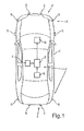
- An in Fig. 1 schematically shown motor vehicle 1 is a passenger car.
- the motor vehicle 1 includes a parking assistance system 2, which is designed to assist the driver when parking in a parking space.
- the parking assistance system 2 comprises a control device 3 and a sensor device 4, which has a multiplicity of ultrasonic sensors 5.
- a plurality of ultrasonic sensors 5 are arranged distributed on the front bumper of the motor vehicle 1, and a plurality of ultrasonic sensors 5 are mounted on the rear bumper.
- at least one ultrasonic sensor 5 is arranged on the left and the right side flank in such a way that the lateral areas can be detected next to the motor vehicle 1.
- the sensor device 4 provides sensor data and transmits this sensor data to the control device 3.
- the control device 3 can determine the respective distances between the motor vehicle 1 and external obstacles on the basis of the sensor data.
- the parking assistance system 2 is used to assist the driver when parking in a parking space. This involves first the detection of a suitable parking space. Such is detected during a passage of the motor vehicle 1 at the parking space. During the passage, the ultrasonic sensors 5 (namely, the lateral ultrasonic sensors 5) detect the lateral area adjacent to the motor vehicle 1. On the basis of the sensor data thus acquired, the control device 3 determines the dimensions of the parking space both in the longitudinal direction and in the transverse direction of the road. The control device 3 also determines the relative position of the parking space with respect to the motor vehicle 1 and then calculates a suitable parking path along which the motor vehicle 1 can be packed into the parking space. This parking space can then be displayed to the driver, such as by means of an output device 6, which may include a speaker and / or a display.
- an output device 6 which may include a speaker and / or a display.
- the parking assistance system 2 may also include a GPS receiver 7, which outputs position signals to the control device 3. These position signals contain information about the respective current global or geographical position of the motor vehicle 1.
- map data are stored, which include a plurality of maps of different regions as well as other environmental information, such as parking, parking restrictions and the like.
- the parking aid system 2 also includes cameras 9, which are arranged distributed on the motor vehicle 1.
- the cameras 9 are optical sensors which detect light in the visible spectral range and can thus take pictures.
- the number and arrangement of the ultrasonic sensors 5 and the cameras 9 are in the embodiment according to Fig. 1 merely by way of example and may vary depending on the embodiment.
- the image data captured by the cameras 9 are transmitted to the control device 3 and can be processed by the control device 3.
- the controller 3 may subject the captured images to pattern recognition in a variety of predetermined patterns, and thus identify predetermined traffic signs. Based on the images, the control device 3 can thus detect further environmental information that is independent of the sensor data of the ultrasonic sensors 5.
- This walkway 10 represents a parking bay, which is located between a road 11 (road) on the one hand and the actual walkway 12 on the other. Between the walkway 10 on the one hand and the road 11 on the other hand there is a first curb 13; between the walkway or the parking bay on the one hand and the actual pedestrian walkway 12 on the other hand, there is a second curb 14, which is arranged in the transverse direction of the road 11 further away than the first curb 13.
- a parking space 15 is located on the walkway 10, between a parking space limiting vehicle 16 on the one hand and the parking space 15 also limiting tree 17 on the other.
- the parking space 15 in the longitudinal direction of the road 11 on the one hand by the motor vehicle 16 and on the other hand by the tree 17 is directly limited.
- the parking space 15 is on the one hand by the first curb 13 and on the other hand by the second curb 14 limited. It is therefore a longitudinal parking space 15 which extends parallel to the road 11 and along the longitudinal direction of the road 11.
- the parking space 15 is first detected by means of the ultrasonic sensors 5 during passage of the motor vehicle 1 at the parking space 15.
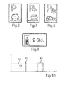
- a time course of echoes such as in Fig. 10 is shown.
- a received signal S of the sensor device 4 ie the echoes
- the time t is plotted.
- the sensor device 4 receives a first echo E1, which corresponds to the tree 17, as well as a second echo E2, which corresponds to the vehicle 16.
- a third echo E3 represents the first curb 13.
- a fourth echo E4 is the second curb 14 in Fig. 2 assigned.
- the second curb 14 or the echo E4 is filtered out, and only the echo E3 of the first curb 13 is taken into account.
- the first curb 13 is in fact interpreted in the prior art as an obstacle that must not be run over by the motor vehicle.
- the control device 3 in the present case detects the above-mentioned further environmental information of the motor vehicle 1, that is, among other things, the information that may be parked on the sidewalk or the parking bay 10.
- This environment information can win the control device 3 based on the map data and the current global position of the motor vehicle 1 and / or based on a recognized in a captured image traffic sign.
- the control device 3 can identify traffic signs in the recorded images, such as those in the Fig. 6 to 8 are shown. According to Fig. 6
- the control device 3 can recognize that the motor vehicle 1 can be partially parked on the sidewalk in the longitudinal direction of the road 11 Fig.
- the control device 3 can also recognize on the basis of the images that the motor vehicle 1 can be parked completely on the sidewalk. In this case, the control device 3 recognizes the direction in which the parking on the sidewalk - seen from the traffic sign - is allowed, ie left and / or right of the traffic sign based on an arrow on the traffic sign. Finally, the control device 3 according to Fig. 8 also recognize that the motor vehicle 1 can be partially parked on the sidewalk, and that perpendicular to the road 11. Here, the controller 3 also recognizes the double arrow shown on the road sign that parking on the sidewalk on the two sides of the road sign is possible.
- the control device 3 can also obtain corresponding information from the map data.
- the control device 3 takes into account only the echo E4 when determining the depth of the parking space 15 and when determining the position of the parking space 15 relative to the motor vehicle 1 of the second curb 14, the first curb 13 is not taken into account. This may in particular be such that the echo E3 of the first curb 13 is filtered out or else the measurement is influenced in such a way by means of the sensor device 4 that only the second curb 14 is measured by the sensor device 4.
- the control device 3 As the outer boundary of the parking space 15, the control device 3 thus considers the second curb 14, and not the first curb 13. This results in the control device 3 recognizing the parking space 15 which is located on the sidewalk or the parking bay 10. This means that the control device 3 can calculate a parking path along which the motor vehicle 1 can be parked in the parking space 15 and thereby can drive over the first curb 13.
- the control device 3 can also identify further traffic signs on the basis of the recorded images, such as traffic signs relating to the parking prohibition, as in the US Pat Fig. 3 to 5 shown.
- the control device 3 can output an information signal, by which the driver is informed about the parking ban.
- the driver can decide for himself whether the parking operation should be carried out or not. This decision can be made, for example, by means of an input device of the parking aid system 2.
- the information signal concerning the parking prohibition can also be output when the traffic sign of a bus stop - as in Fig. 5 is shown - and the distance between the motor vehicle 1 and the traffic sign of the bus stop is smaller than a predetermined limit, namely in particular less than 15 m.
- a traffic sign can be identified, as it is in Fig. 9 is shown.
- This traffic sign means that a parking disc is required. If the control device 3 recognizes this environmental information - be it from the camera images or from the map data - then a corresponding information signal is output, and the driver is informed of the need for the parking disc.
Abstract
Description
- Die Erfindung betrifft ein Verfahren zum Erkennen einer Parklücke für ein Kraftfahrzeug mithilfe eines Parkhilfesystems des Kraftfahrzeugs. Das Parkhilfesystem ermittelt einen geometrischen Parameter der Parklücke anhand von Sensordaten einer Sensoreinrichtung des Parkhilfesystems, nämlich insbesondere anhand von Sensordaten zumindest eines Ultraschallsensors. Es werden außerdem weitere, von den Sensordaten unterschiedliche - insbesondere nicht auf die Parklücke selbst bezogene - Umgebungsinformationen des Kraftfahrzeugs mittels des Parkhilfesystems erfasst, und das Parkhilfesystem erkennt die Parklücke anhand des geometrischen Parameters der Parklücke sowie unter Berücksichtigung der weiteren Umgebungsinformationen des Kraftfahrzeugs. Die Erfindung betrifft außerdem ein Parkhilfesystem zum Durchführen des erfindungsgemäßen Verfahrens, wie auch ein Kraftfahrzeug mit einem derartigen Parkhilfesystem.
- Parkhilfesysteme für Kraftfahrzeuge sind bereits Stand der Technik. Sie dienen zum Unterstützen des Fahrers beim Einparken des Kraftfahrzeugs in eine Parklücke, sei es eine Querparklücke oder aber eine Längsparklücke. Solche Parkhilfesysteme beinhalten in der Regel Ultraschallsensoren, welche während einer Vorbeifahrt des Kraftfahrzeugs an einer potentiellen Parklücke Sensordaten bereitstellen, anhand welcher erkannt werden kann, ob die potentielle Parklücke für den Parkvorgang geeignet ist oder nicht - es wird also die Parklücke anhand der Sensordaten erkannt. Dabei wird insbesondere die Abmessung der Parklücke in Längsrichtung der Straße ermittelt, wie auch die Tiefe der Parklücke. Wird eine potentielle Parklücke als eine für den Parkvorgang geeignete Parklücke interpretiert, so wird dies dem Fahrer angezeigt, und der Fahrer kann entscheiden, ob der Parkvorgang durchgeführt werden soll oder nicht. Hier gibt es unterschiedliche Möglichkeiten: Es existieren so genannte vollautomatische Parkhilfesysteme, wie auch halbautomatische bzw. semi-autonome Parkhilfesysteme. Bei vollautomatischen Parkhilfesystemen braucht der Fahrer den Parkvorgang lediglich freizugeben; das Parkhilfesystem übernimmt dabei die Lenkung und gegebenenfalls sogar auch die Beschleunigung und das Abbremsen. Bei halbautomatischen Systemen hingegen wird dem Fahrer angezeigt, in weiche Richtung er lenken soll, damit das Kraftfahrzeug in die Parklücke eingeparkt wird.
- Problematisch können solche Situationen sein, bei welchen das Kraftfahrzeug teilweise oder vollständig auf einem Gehweg eingeparkt werden kann. Solche Parksituationen können nicht ohne weiteres anhand von Sensordaten eines Ultraschallsensors erkannt werden. Dies gilt insbesondere dann, wenn sich die potentielle Parklücke zwischen zwei anderen Kraftfahrzeugen befindet, von denen eines auf der Straße und das andere zur Hälfte oder vollständig auf dem Gehweg geparkt ist. Selbiges Problem ergibt sich auch dann, wenn das eine Kraftfahrzeug teilweise auf dem Gehweg und das andere vollständig auf dem Gehweg geparkt ist, oder aber eine potentielle Parklücke gegeben ist, welche nur durch ein einziges Kraftfahrzeug begrenzt ist. Bei derartigen Situationen kann das Parkhilfesystem nicht genau einschätzen, wie tief die potentielle Parklücke tatsächlich ist, sodass das Parkhilfesystem die Endposition des Kraftfahrzeugs in der Parklücke nicht oder nur mit einem großen Messaufwand bestimmen kann.
- Die Druckschrift
DE 10 2004 047 507 A1 beschreibt ein Verfahren sowie ein Parkhilfesystem zur Erkennung einer freien Parklücke für ein Kraftfahrzeug. Es werden zunächst geometrische Parameter der Parklücke bestimmt, und es wird entschieden, ob die Parklücke eine ausreichende Größe für das Kraftfahrzeug aufweist und somit für den Parkvorgang geeignet ist oder nicht. Des Weiteren werden auch Karteninformationen eines Navigationssystems des Kraftfahrzeugs oder aber Kamerabilder berücksichtigt, sodass weitere, nicht auf die Parklücke bezogene Umgebungsinformationen - etwa ein Parkverbot - erfasst werden. Die Kenntnis dieser Informationen wird dazu verwendet, eine zunächst als geeignet erkannte Parklücke auszuschließen und die Anzeige einer zunächst als geeignet angesehenen Parklücke für den Fahrer zu unterdrücken. - Es ist Aufgabe der Erfindung, eine Lösung aufzuzeigen, wie bei einem Verfahren der eingangs genannten Gattung eine geeignete Parklücke auch dann erkannt werden kann, wenn das Kraftfahrzeug zumindest teilweise auf einem Bordstein bzw. einem Gehweg geparkt werden kann.
- Diese Aufgabe wird erfindungsgemäß durch ein Verfahren, ein Parkhilfesystem sowie durch ein Kraftfahrzeug mit den Merkmalen gemäß den jeweiligen unabhängigen Patentansprüchen gelöst. Vorteilhafte Ausführungen der Erfindung sind Gegenstand der abhängigen Patentansprüche, der Beschreibung und der Figuren.
- Bei einem erfindungsgemäßen Verfahren wird eine Parklücke für ein Kraftfahrzeug mithilfe eines Parkhilfesystems des Kraftfahrzeugs erkannt. Das Parkhilfesystem ermittelt einen geometrischen Parameter der Parklücke anhand von Sensordaten einer Sensoreinrichtung des Parkhilfesystems, nämlich beispielsweise anhand von Sensordaten zumindest eines Ultraschallsensors, Es werden auch weitere, von den Sensordaten unterschiedliche - insbesondere von der Parklücke unabhängige bzw. nicht auf die Parklücke selbst bezogene - Umgebungsinformationen des Kraftfahrzeugs mittels des Parkhilfesystems erfasst. Diese weiteren Umgebungsinformationen werden bei der Erkennung der Parklücke dahingehend berücksichtigt, dass der geometrische Parameter der Parklücke - nämlich insbesondere die Tiefe der Parklücke und/oder die relative Position der Parklücke des Kraftfahrzeugs - auch in Abhängigkeit von den weiteren Umgebungsinformationen des Kraftfahrzeugs bestimmt wird.
- Anders als im Gegenstand gemäß Druckschrift
DE 10 2004 047 507 A1 - dort werden die weiteren Umgebungsinformationen lediglich dazu verwendet, die Anzeige einer geeigneten Parklücke gegebenenfalls zu unterdrücken - werden die weiteren Umgebungsinformationen erfindungsgemäß auch bei der Ermittlung des geometrischen Parameters der Parklücke berücksichtigt, nämlich insbesondere bei der Bestimmung der Tiefe der Parklücke und/oder der relativen Position der Parklücke (insbesondere in Querrichtung der Straße) bezüglich des Kraftfahrzeugs. Auf diesem Wege gelingt es, den geometrischen Parameter der Parklücke mit höchster Genauigkeit auch dann zu bestimmen, wenn das Kraftfahrzeug zumindest teilweise auf einem Bordstein bzw. einem Gehweg geparkt werden darf und die potentielle Parklücke durch zwei andere Kraftfahrzeuge begrenzt ist, die in Querrichtung der Straße unterschiedlich geparkt sind, oder aber die Parklücke lediglich durch ein einziges Kraftfahrzeug begrenzt ist. Wird beispielsweise als weitere Umgebungsinformation erfasst, dass das Kraftfahrzeug teilweise oder vollständig auf dem Gehweg geparkt werden darf, so kann beispielsweise der die Straße begrenzende Bordstein durch das Parkhilfesystem bei der Bestimmung des geometrischen Parameters der Parklücke ignoriert werden, und das Parkhilfesystem kann beispielsweise nach einem weiteren Bordstein suchen, der sich weiter weg vom Kraftfahrzeug befindet. Dieser zweite Bordstein kann dann zur Bestimmung des geometrischen Parameters der Parklücke - insbesondere der Tiefe - herangezogen werden. Somit wird verhindert, dass der erste Bordstein (auf welchem geparkt werden darf) durch das Parkhilfesystem als ein Hindernis interpretiert wird und das Kraftfahrzeug vor dem Bordstein geparkt wird. Dieser erste Bordstein kann durch das Kraftfahrzeug überfahren werden, sodass das Kraftfahrzeug ordnungsgemäß eingeparkt werden kann. - Als geometrischer Parameter, der anhand der Sensordaten der Sensoreinrichtung sowie in Abhängigkeit von den weiteren Umgebungsinformationen des Kraftfahrzeugs bestimmt wird, wird bevorzugt eine Tiefe der Parklücke in Querrichtung der Fahrbahn und/oder eine relative Position der Parklücke bezüglich des Kraftfahrzeugs bestimmt. In Abhängigkeit von den weiteren Umgebungsinformationen kann also insgesamt die zur Verfügung stehende Breite der Parklücke und somit die genaue Position der Parklücke relativ zum Kraftfahrzeug bestimmt werden. Hierdurch wird erreicht, dass eine plausible Parkbahn durch das Parkhilfesystem berechnet werden kann, entlang welcher das Kraftfahrzeug in die Parklücke geführt werden kann. Es wird außerdem erreicht, dass das Kraftfahrzeug ordnungsgemäß in Querrichtung der Straße, und nicht etwa zu nahe an der Straße eingeparkt wird. Die zur Verfügung stehende Tiefe der Parklücke kann somit wirkungsvoll genutzt werden.
- Für die Erfassung der weiteren Umgebungsinformationen sind vorliegend zwei Ausführungsformen vorgesehen: Zum einen können die weiteren Umgebungsinformationen anhand eines Bildes erfasst werden, welches mittels einer Kamera des Parkhilfesystems aufgenommen wird. Eine solche Kamera kann die Umgebung des Kraftfahrzeugs fortlaufend erfassen, sodass die jeweiligen Umgebungsinformationen situationsabhängig und bedarfsgerecht erfasst werden können. Ergänzend oder alternativ können die weiteren Umgebungsinformationen auch anhand von Kartendaten eines Navigationssystems des Kraftfahrzeugs sowie unter Berücksichtigung der aktuellen geographischen bzw. globalen Position des Kraftfahrzeugs gewonnen werden. Diese Ausführungsform hat den Vorteil, dass in solchen Kartendaten auch derartige Umgebungsinformationen enthalten sein können, die anhand eines Kamerabildes nicht erfasst werden können. Ein weiterer Vorteil besteht darin, dass ein in der Regel ohnehin vorhandenes Navigationssystem verwendet werden kann und gegebenenfalls auf eine Kamera verzichtet werden kann. Sowohl mithilfe einer Kamera als auch mittels eines Navigationssystems können zahlreiche Umgebungsinformationen erfasst werden, nämlich beispielsweise ein Parkverbot, die Möglichkeit des Parkens auf einem Gehweg und dergleichen.
- Besonders bevorzugt ist es, wenn in dem aufgenommenen Bild ein Verkehrszeichen identifiziert wird. Dann können die weiteren Umgebungsinformationen aus dem Abbild des Verkehrszeichens in dem aufgenommenen Bild gewonnen werden. Somit können unterschiedlichste Umgebungsinformationen durch das Parkhilfesystem erfasst werden, denn das Parkhilfesystem kann die aufgenommenen Bilder einer Mustererkennung hinsichtlich einer Vielzahl von möglichen relevanten Verkehrszeichen unterziehen. In dem aufgenommenen Bild kann beispielsweise das Verkehrszeichen detektiert werden, dass das Kraftfahrzeug teilweise oder vollständig auf einem Gehweg geparkt werden kann. Diese Art der Erfassung der Umgebungsinformationen ist auch besonders zuverlässig, es können nämlich auch ganz neue Verkehrszeichen erkannt werden, die beispielsweise erst seit einer kurzen Zeit vorhanden sind und somit noch nicht in den Kartendaten eines Navigationssystems abgespeichert sind.
- Wie bereits ausgeführt, wird in einer Ausführungsform die Zulässigkeit des teilweisen oder vollständigen Parkens auf einem Gehweg bzw. einem Bordstein als weitere Umgebungsinformation erfasst, sei es anhand von Kartendaten eines Navigationssystems, sei es anhand eines mittels einer Kamera aufgenommenen Bildes. Diese Umgebungsinformation ermöglicht die genaue Bestimmung der Tiefe der Parklücke, sodass auch eine entsprechende zuverlässige Parkbahn für den Parkvorgang durch das Parkhilfesystem berechnet werden kann. Ist das Parken auf einem Bordstein zulässig, so kann das Parkhilfesystem nämlich die genannte Parkbahn auch in der Weise berechnen, dass ein erkannter Bordstein - welcher in der Regel durch bekannte Parkhilfesysteme als ein Hindernis und somit als eine Begrenzung der Parklücke interpretiert wird - durch das Kraftfahrzeug auch überfahren wird und bei der Berechnung der Tiefe der Parklücke nicht berücksichtigt wird. Somit ist ein zuverlässiges Parken möglich.
- Es existieren auch Parkbuchten, die sich entlang einer Straße erstrecken und durch zwei Bordsteine seitlich begrenzt sind: Der erste Bordstein trennt die Parkbucht von der tatsächlichen Straße und der zweite Bordstein begrenzt die Parkbucht von dem tatsächlichen Gehweg. Eine derartige Parkbucht fällt vorliegend unter den allgemeinen Begriff "Gehweg", sodass der Begriff "Gehweg" vorliegend auch solche Parkeinbuchtungen beinhaltet, die mittels eines Bordsteins von der Straße getrennt sind.
- In einer Ausführungsform wird in Abhängigkeit von der Information über die Zulässigkeit des Parkens auf dem Gehweg eine Annahme bezüglich der Position eines die Parklücke begrenzenden Bordsteins getroffen. Hier wird also der seitliche Abstand bestimmt, in welchem der Bordstein erwartet wird. Wird die Information über die Zulässigkeit des Parkens auf dem Gehweg - nämlich in einer durch zwei Bordsteine begrenzten Parkbucht - durch das Parkhilfesystem erfasst, so kann das Parkhilfesystem den ersten Bordstein bei der Bestimmung der Tiefe der Parklücke ignorieren und nach einem zweiten Bordstein suchen. Somit kann der zweite Bordstein aufgefunden und die Tiefe der Parklücke korrekt bestimmt werden.
- Also ist in einer Ausführungsform vorgesehen, dass - falls anhand der weiteren Umgebungsinformationen erkannt wird, dass das Kraftfahrzeug zumindest teilweise auf dem Gehweg geparkt werden darf - ein in Richtung seitlich vom Kraftfahrzeug weg befindlicher erster Bordstein durch das Parkhilfesystem bei der Bestimmung des geometrischen Parameters der Parklücke, insbesondere der Tiefe, ignoriert wird. Es wird somit ermöglicht, dass der erste Bordstein durch das Kraftfahrzeug überfahren wird und das Kraftfahrzeug somit ordnungsgemäß auf dem Gehweg geparkt werden kann.
- Wird anhand der weiteren Umgebungsinformationen erkannt, dass das Kraftfahrzeugs zumindest teilweise auf dem Gehweg geparkt werden darf, so wird bevorzugt ein in Richtung seitlich vom Kraftfahrzeug weg befindlicher zweiter Bordstein erfasst und bei der Bestimmung des geometrischen Parameters, insbesondere der Tiefe, berücksichtigt. Das Ignorieren des ersten Bordsteins und die Berücksichtigung des zweiten Bordsteins kann grundsätzlich auf zwei unterschiedliche Art und Weisen erfolgen: Zum einen kann die Messung mithilfe der Sensoreinrichtung bereits vorab beeinflusst werden, nämlich dann, wenn die Zulässigkeit des Parkens auf dem Gehweg erkannt wird. Hier kann die Sensoreinrichtung - nämlich insbesondere zumindest ein Ultraschallsensor - in der Weise angesteuert werden, dass ausschließlich der Abstand zum zweiten Bordstein gemessen wird. Dabei kann beispielsweise eine Abtastfrequenz und/oder die Reichweite der Sensoreinrichtung verändert werden. Zum anderen kann auch vorgesehen sein, dass nach der Messung die durch die Sensoreinrichtung bereitgestellten Sensordaten in der Weise verarbeitet werden, dass der erste Bordstein "herausgefiltert" wird und lediglich der zweite Bordstein, der sich weiter weg vom Kraftfahrzeug befindet, bei der Bestimmung der Tiefe der Parklücke berücksichtigt wird. Beide Ausführungsformen führen dazu, dass der erste Bordstein durch das Kraftfahrzeug überfahren werden kann, während der zweite Bordstein eine tatsächliche Begrenzung der Parklücke in Querrichtung der Straße nach außen hin darstellt.
- Anhand der weiteren Umgebungsinformationen kann in einer Ausführungsform auch festgestellt werden, ob das Parken in einer anhand der Sensordaten erkannten potentiellen Parklücke zulässig ist oder nicht. Nach Feststellen eines Parkverbots kann dann ein Informationssignal durch das Parkhilfesystem ausgegeben werden, durch welches der Fahrer über das Parkverbot informiert wird. Somit kann der Fahrer darüber informiert werden, ob das Einparken überhaupt zulässig ist oder nicht. Er kann dann selbst entscheiden, ob er den Parkvorgang tatsächlich durchführen will oder nicht. Dazu kann der Fahrer eine entsprechende Eingabe an einer Eingabeeinrichtung des Parkhilfesystems vornehmen, über welche festgelegt wird, ob das Parkhilfesystem einen Parkvorgang durchführen soll, also insbesondere eine Parkbahn berechnen soll oder nicht.
- Es kann auch vorgesehen sein, dass nach Feststellen des Parkverbots eine Parkaltenative für das Einparken durch das Parkhilfesystem vorgeschlagen wird. Dies kann beispielsweise so aussehen, dass diese Parkalternative anhand von Kartendaten des Navigationssystems sowie unter Berücksichtigung der aktuellen globalen Position des Kraftfahrzeugs erkannt und dem Fahrer vorgeschlagen wird. Dies ist besonders benutzerfreundlich, denn der Fahrer muss nicht alleine nach möglichen Parkalternativen suchen, sondern er wird über diese Parkalternativen mittels des Parkhilfesystems informiert.
- Also kann das Parkhilfesystem ein Parkverbot erkennen, und zwar beispielsweise anhand von Kartendaten des Navigationssystems und/oder anhand eines Kamerabildes. Als Parkverbot können auch indirekte Verkehrszeichen gelten, die durch das Parkhilfesystem erkannt werden. Als derartiges Verkehrszeichen kann zum Beispiel das Zeichen einer Bushattestelle, ein Stopp-Zeichen, ein Bahnübergang und dergleichen gelten. Das Parkhilfesystem erkennt dann beispielsweise, dass das Einparken in einem Abstand von 15m von einer Bushaltestelle nicht erlaubt ist. Ein solches Parkverbot kann auch anhand von Kartendaten des Navigationssystems erkannt werden. Will der Fahrer beispielsweise an einem Kreuzungsbereich oder aber zu nahe an einem Zebrastreifen einparken, kann er durch das Parkhilfesystem gewarnt werden. Selbiges gilt, wenn der Fahrer beispielsweise außerorts auf der Fahrbahn einparken möchte.
- Entsprechend den Länderinformationen aus dem Navigationssystem kann die Vorgabe für das automatische Parken verändert werden, zum Beispiel für Länder, in denen das Parken auf Gehwegen generell erlaubt ist. So kann das Parkhilfesystem automatisch zwischen unterschiedlichen länderspezifischen Gesetzen bezüglich des Parkens umschalten. Entsprechend der Länderinformation aus dem Navigationssystem kann auch das Piktogramm bzw. das Muster unterschiedlicher Verkehrszeichen verändert werden, welche durch das Parkhilfesystem anhand von Kamerabildern erkannt werden sollen.
- In einer Ausführungsform ist vorgesehen, dass das Parkhilfesystem als weitere Umgebungsinformation erkennt, dass in der erkannten Parklücke eine Parkscheibe notwendig ist. Das Parkhilfesystem kann dann den Fahrer entsprechend auf diesen Umstand hinweisen, sodass der Fahrer durch das Parkhilfesystem darüber informiert wird, dass eine Parkscheibe erforderlich ist.
- Um zu vermeiden, dass der seitliche Abstand des Kraftfahrzeugs zu einer Fahrstreifenbegrenzung oder einer baulichen Fahrspurtrennung (Bordstein) in der Endposition in der Parklücke zu klein wird, kann anhand eines aufgenommenen Bildes diese Fahrstreifenbegrenzung oder die bauliche Fahrspurtrennung erkannt werden. Wird durch das Parkhilfesystem erkannt, dass der Abstand des geparkten Kraftfahrzeugs zu der genannten Begrenzung kleiner als ein vorgegebener Grenzwert ist, kann ein Warnsignal ausgegeben werden, mittels welchem der Fahrer über diesen zu kleinen Abstand informiert wird. Alternativ kann der Vorschlag bzw. die Anzeige dieser Parklücke für den Parkvorgang durch das Parkhilfesystem unterdrückt werden.
- Ein erfindungsgemäßes Parkhilfesystem ist zum Durchführen eines erfindungsgemäßen Verfahrens ausgebildet.
- Ein erfindungsgemäßes Kraftfahrzeug weist ein erfindungsgemäßes Parkhiffesystem auf.
- Die mit Bezug auf das erfindungsgemäße Verfahren vorgestellten bevorzugten Ausführungsformen und deren Vorteile gelten entsprechend für das erfindungsgemäße Parkhilfesystem sowie für das erfindungsgemäße Kraftfahrzeug.
- Weitere Merkmale der Erfindung ergeben sich aus den Ansprüchen, den Figuren und der Figurenbeschreibung. Alle vorstehend in der Beschreibung genannten Merkmale und Merkmalskombinationen sowie die nachfolgend in der Figurenbeschreibung genannten und/oder in den Figuren alleine gezeigten Merkmale und Merkmalskombinationen sind nicht nur in der jeweils angegebenen Kombination, sondern auch in anderen Kombinationen oder aber in Alleinstellung verwendbar.
- Die Erfindung wird nun anhand einzelner bevorzugter Ausführungsformen, wie auch unter Bezugnahme auf die beigefügten Zeichnungen näher erläutert.
- Es zeigen:
- Fig. 1
- in schematischer Darstellung ein Kraftfahrzeug mit einem Parkhilfesystem gemäß einer Ausführungsform der Erfindung;
- Fig. 2
- in schematischer Darstellung eine Parksituation, in welcher das Kraftfahrzeug auf einem Gehweg eingeparkt werden kann;
- Fig. 3 bis 9
- in schematischer Darstellung jeweils ein Verkehrszeichen, welches durch das Parkhilfesystem anhand von Bildern einer Kamera identifiziert wird; und
- Fig. 10
- einen zeitlichen Verlauf von Empfangssignalen eines Ultraschallsensors beim Vermessen einer Parklücke während der Vorbeifahrt des Kraftfahrzeugs an der Parklücke.
- Ein in
Fig. 1 in schematischer Darstellung gezeigtes Kraftfahrzeug 1 ist ein Personenkraftwagen. Das Kraftfahrzeug 1 beinhaltet ein Parkhilfesystem 2, welches zum Unterstützen des Fahrers beim Einparken in eine Parklücke ausgebildet ist. Das Parkhilfesystem 2 umfasst eine Steuereinrichtung 3 sowie eine Sensoreinrichtung 4, welche eine Vielzahl von Ultraschallsensoren 5 aufweist. Dabei sind eine Vielzahl von Ultraschallsensoren 5 an dem vorderen Stoßfänger des Kraftfahrzeugs 1 verteilt angeordnet, und eine Vielzahl von Ultraschallsensoren 5 sind am hinteren Stoßfänger angebracht. Dabei ist jeweils zumindest ein Ultraschallsensor 5 derart an der linken und der rechten Seitenflanke angeordnet, dass die seitlichen Bereiche neben dem Kraftfahrzeug 1 erfasst werden können. - Die Sensoreinrichtung 4 stellt Sensordaten bereit und übermittelt diese Sensordaten an die Steuereinrichtung 3. Die Steuereinrichtung 3 kann anhand der Sensordaten jeweilige Abstände zwischen dem Kraftfahrzeug 1 und fahrzeugexternen Hindernissen bestimmen.
- Wie bereits ausgeführt, dient das Parkhilfesystem 2 zum Unterstützen des Fahrers beim Einparken in eine Parklücke. Dies beinhaltet zunächst die Erkennung einer geeigneten Parklücke. Eine solche wird während einer Vorbeifahrt des Kraftfahrzeugs 1 an der Parklücke erfasst. Während der Vorbeifahrt erfassen die Ultraschallsensoren 5 (nämlich die seitlichen Ultraschallsensoren 5) den seitlichen Bereich neben dem Kraftfahrzeug 1. Anhand der so erfassten Sensordaten ermittelt die Steuereinrichtung 3 die Abmessungen der Parklücke sowohl in Längsrichtung als auch in Querrichtung der Straße. Die Steuereinrichtung 3 bestimmt auch die relative Position der Parklücke bezüglich des Kraftfahrzeugs 1 und berechnet dann eine geeignete Parkbahn, entlang welcher das Kraftfahrzeug 1 in die Parklücke eingepackt werden kann. Diese Parklücke kann dann dem Fahrer angezeigt werden, etwa mithilfe einer Ausgabeeinrichtung 6, die einen Lautsprecher und/oder ein Display umfassen kann.
- Das Parkhilfesystem 2 kann auch einen GPS-Empfänger 7 umfassen, welcher Positionssignale an die Steuereinrichtung 3 abgibt. Diese Positionssignale beinhalten Informationen über die jeweils augenblickliche globale bzw. geographische Position des Kraftfahrzeugs 1. In einem Speicher 8 sind Kartendaten abgelegt, welche eine Vielzahl von Karten unterschiedlicher Regionen sowie auch weitere Umgebungsinformationen beinhalten, wie insbesondere Parkmöglichkeiten, Parkverbote und dergleichen.
- Zum Parkhilfesystem 2 gehören auch Kameras 9, die an dem Kraftfahrzeug 1 verteilt angeordnet sind. Die Kameras 9 sind optische Sensoren, welche Licht im sichtbaren Spektralbereich detektieren und so Bilder aufnehmen können.
- Die Anzahl und die Anordnung der Ultraschallsensoren 5 sowie der Kameras 9 sind im Ausführungsbeispiel gemäß
Fig. 1 lediglich beispielhaft und können je nach Ausführungsform variieren. - Die von den Kameras 9 erfassten Bilddaten werden an die Steuereinrichtung 3 übermittelt und können durch die Steuereinrichtung 3 verarbeitet werden. Die Steuereinrichtung 3 kann die aufgenommenen Bilder einer Mustererkennung hinsichtlich einer Vielzahl vorbestimmter Muster unterziehen und auf diese Art und Weise vorbestimmte Verkehrszeichen identifizieren. Anhand der Bilder kann die Steuereinrichtung 3 also weitere Umgebungsinformationen erfassen, die unabhängig von den Sensordaten der Ultraschallsensoren 5 sind.
- Vorliegend richtet sich das Interesse auf das Einparken des Kraftfahrzeugs 1 auf einem Gehweg, wie er in schematischer Darstellung in
Fig. 2 dargestellt und mit 10 bezeichnet ist. Dieser Gehweg 10 stellt eine Parkbucht dar, die sich zwischen einer Straße 11 (Fahrbahn) einerseits und dem tatsächlichen Gehweg 12 andererseits befindet. Zwischen dem Gehweg 10 einerseits und der Straße 11 andererseits befindet sich ein erster Bordstein 13; zwischen dem Gehweg bzw. der Parkbucht einerseits und dem tatsächlichen Fußgängerweg 12 andererseits befindet sich ein zweiter Bordstein 14, der in Querrichtung der Straße 11 weiter weg als der erste Bordstein 13 angeordnet ist. Eine Parklücke 15 befindet sich auf dem Gehweg 10, und zwar zwischen einem die Parklücke begrenzenden Fahrzeug 16 einerseits und einem die Parklücke 15 ebenfalls begrenzenden Baum 17 andererseits. Also ist die Parklücke 15 in Längsrichtung der Straße 11 einerseits durch das Kraftfahrzeug 16 und andererseits durch den Baum 17 unmittelbar begrenzt. In Querrichtung der Straße 11 hingegen ist die Parklücke 15 einerseits durch den ersten Bordstein 13 und andererseits durch den zweiten Bordstein 14 begrenzt. Es handelt sich also um eine Längsparklücke 15, die sich parallel zur Straße 11 bzw. entlang der Längsrichtung der Straße 11 erstreckt. - Die Parklücke 15 wird zunächst mittels der Ultraschallsensoren 5 während einer Vorbeifahrt des Kraftfahrzeugs 1 an der Parklücke 15 erfasst. Bei dem Ausführungsbeispiel gemäß
Fig. 2 entsteht dabei ein zeitlicher Verlauf von Echos, wie er beispielsweise inFig. 10 dargestellt ist. Auf der y-Achse ist ein Empfangssignal S der Sensoreinrichtung 4 (also die Echos) aufgetragen, und auf der x-Achse ist die Zeit t aufgetragen. Wie ausFig. 10 hervorgeht, empfängt die Sensoreinrichtung 4 ein erstes Echo E1, welches dem Baum 17 entspricht, wie auch ein zweites Echo E2, welches dem Fahrzeug 16 entspricht. Ein drittes Echo E3 stellt den ersten Bordstein 13 dar. Schließlich ist ein viertes Echo E4 dem zweiten Bordstein 14 inFig. 2 zugeordnet. - Mit weiterem Bezug auf
Fig. 10 wird bei den aus dem Stand der Technik bekannten Parkhilfesystemen der zweite Bordstein 14 bzw. das Echo E4 herausgefiltert, und lediglich das Echo E3 des ersten Bordsteins 13 wird berücksichtigt. Dies führt im Stand der Technik dazu, dass bei der Parksituation gemäßFig. 2 das Kraftfahrzeug vor dem ersten Bordstein 13, also auf der Straße eingeparkt wird, oder aber überhaupt keine Parklücke erkannt wird. Der erste Bordstein 13 wird nämlich im Stand der Technik als ein Hindernis interpretiert, welches durch das Kraftfahrzeug nicht überfahren werden darf. - Hingegen erfasst die Steuereinrichtung 3 vorliegend die oben genannten weiteren Umgebungsinformationen des Kraftfahrzeugs 1, also unter Anderem auch die Information, dass auf dem Gehweg bzw. der Parkbucht 10 eingeparkt werden darf. Diese Umgebungsinformation kann die Steuereinrichtung 3 anhand der Kartendaten und der aktuellen globalen Position des Kraftfahrzeugs 1 und/oder anhand eines in einem aufgenommenen Bild erkannten Verkehrszeichens gewinnen. Die Steuereinrichtung 3 kann in den aufgenommenen Bildern nämlich Verkehrszeichen identifizieren, wie sie beispielsweise in den
Fig. 6 bis 8 dargestellt sind. GemäßFig. 6 kann die Steuereinrichtung 3 erkennen, dass das Kraftfahrzeug 1 teilweise auf dem Gehweg eingeparkt werden kann, und zwar in Längsrichtung der Straße 11. Wie inFig. 7 dargestellt ist, kann die Steuereinrichtung 3 auch anhand der Bilder erkennen, dass das Kraftfahrzeug 1 vollständig auf dem Gehweg geparkt werden kann. Dabei erkennt die Steuereinrichtung 3 anhand eines auf dem Verkehrszeichen dargestellten Pfeils die Richtung, in welche das Parken auf dem Gehweg - von dem Verkehrszeichen aus gesehen - erlaubt ist, also links und/oder rechts von dem Verkehrszeichen. Schließlich kann die Steuereinrichtung 3 gemäßFig. 8 auch erkennen, dass das Kraftfahrzeug 1 teilweise auf dem Gehweg eingeparkt werden kann, und zwar senkrecht zur Straße 11. Hier erkennt die Steuereinrichtung 3 auch den auf dem Verkehrszeichen dargestellten Doppelpfeil, dass das Einparken auf dem Gehweg auf den beiden Seiten des Verkehrszeichens möglich ist. - Entsprechende Informationen kann die Steuereinrichtung 3 auch aus den Kartendaten gewinnen.
- Wird nun durch die Steuereinrichtung 3 die Information erfasst, dass das Parken auf dem Gehweg 10 möglich ist, so berücksichtigt die Steuereinrichtung 3 bei der Bestimmung der Tiefe der Parklücke 15 sowie bei der Bestimmung der Position der Parklücke 15 relativ zum Kraftfahrzeug 1 ausschließlich das Echo E4 des zweiten Bordsteins 14, wobei der erste Bordstein 13 nicht berücksichtigt wird. Dies kann insbesondere so aussehen, dass das Echo E3 des ersten Bordsteins 13 herausgefiltert wird oder aber die Messung mithilfe der Sensoreinrichtung 4 derart beeinflusst wird, dass durch die Sensoreinrichtung 4 ausschließlich der zweite Bordstein 14 vermessen wird.
- Als die äußere Begrenzung der Parklücke 15 betrachtet die Steuereinrichtung 3 also den zweiten Bordstein 14, und nicht etwa den ersten Bordstein 13. Dies führt dazu, dass die Steuereinrichtung 3 die Parklücke 15 erkennt, die sich auf dem Gehweg bzw. der Parkbucht 10 befindet. Dies bedeutet, dass die Steuereinrichtung 3 eine Parkbahn berechnen kann, entlang welcher das Kraftfahrzeug 1 in die Parklücke 15 eingeparkt werden kann und dabei den ersten Bordstein 13 überfahren kann.
- Die Steuereinrichtung 3 kann anhand der aufgenommenen Bilder auch weitere Verkehrszeichen identifizieren, und zwar etwa Verkehrszeichen betreffend das Parkverbot, wie in den
Fig. 3 bis 5 dargestellt. Werden die Verkehrszeichen gemäß denFig. 3 bzw. 4 erkannt, so kann die Steuereinrichtung 3 ein Informationssignal ausgeben, durch welches der Fahrer über das Parkverbot informiert wird. Hier kann der Fahrer selbst entscheiden, ob der Parkvorgang durchgeführt werden soll oder nicht. Diese Entscheidung kann beispielsweise mithilfe einer Eingabeeinrichtung des Parkhilfesystems 2 getroffen werden. Das Informationssignal betreffend das Parkverbot kann auch dann ausgegeben werden, wenn durch die Steuereinrichtung 3 das Verkehrszeichen einer Bushaltestelle - wie inFig. 5 dargestellt - erkannt wird und der Abstand zwischen dem Kraftfahrzeug 1 und dem Verkehrszeichen der Bushaltestelle kleiner als ein vorgegebener Grenzwert ist, nämlich insbesondere kleiner als 15 m. - Durch die Steuereinrichtung 3 kann auch ein Verkehrszeichen identifiziert werden, wie es in
Fig. 9 dargestellt ist. Dieses Verkehrszeichen bedeutet, dass eine Parkscheibe erforderlich ist. Erkennt die Steuereinrichtung 3 diese Umgebungsinformation - sei es anhand der Kamerabilder, sei es anhand der Kartendaten - so wird ein entsprechendes Informationssignal ausgegeben, und der Fahrer wird über die Notwendigkeit der Parkscheibe informiert.
Claims (13)
- Verfahren zum Erkennen einer Parklücke (15) für ein Kraftfahrzeug (1) mithilfe eines Parkhilfesystems (2) des Kraftfahrzeugs (1), mit den Schritten:- Ermitteln eines geometrischen Parameters der Parklücke (15) anhand von Sensordaten einer Sensoreinrichtung (4) des Parkhilfesystems (2),- Erfassen von weiteren, von den Sensordaten unterschiedlichen Umgebungsinformationen des Kraftfahrzeugs (1) mittels des Parkhilfesystems (2) und- Erkennen der Parklücke (15) anhand des geometrischen Parameters der Parklücke (15) und hierbei Berücksichtigen der weiteren Umgebungsinformationen,
dadurch gekennzeichnet, dass
das Berücksichtigen der weiteren Umgebungsinformationen umfasst, dass der geometrische Parameter der Parklücke (15) auch in Abhängigkeit von den weiteren Umgebungsinformationen des Kraftfahrzeugs (1) bestimmt wird. - Verfahren nach Anspruch 1,
dadurch gekennzeichnet, dass
als geometrischer Parameter eine Tiefe der Parklücke (15) in Querrichtung einer Fahrbahn (11), auf welcher sich das Kraftfahrzeug (1) beim Erfassen der Sensordaten bewegt, und/oder eine relative Position der Parklücke (15) bezüglich des Kraftfahrzeugs (1) bestimmt wird. - Verfahren nach Anspruch 1 oder 2,
dadurch gekennzeichnet, dass
die weiteren Umgebungsinformationen erfasst werden:- anhand eines mittels einer Kamera (9) des Parkhilfesystems (2) aufgenommenen Bildes der Fahrzeugumgebung und/oder- anhand von Kartendaten eines Navigationssystems (7, 8) des Kraftfahrzeugs (1) und anhand der aktuellen geografischen Position des Kraftfahrzeugs (1). - Verfahren nach Anspruch 3,
dadurch gekennzeichnet, dass
in dem aufgenommenen Bild ein Verkehrszeichen identifiziert wird und die weiteren Umgebungsinformationen aus dem Abbild des Verkehrszeichens gewonnen werden. - Verfahren nach einem der vorhergehenden Ansprüche,
dadurch gekennzeichnet, dass
als weitere Umgebungsinformationen die Zulässigkeit des teilweisen oder vollständigen Parkens auf einem Gehweg (10) erfasst wird. - Verfahren nach Anspruch 5,
dadurch gekennzeichnet, dass
in Abhängigkeit von der Information über die Zulässigkeit des Parkens auf dem Gehweg (10) eine Annahme bezüglich der Position eines die Parklücke (15) begrenzenden Bordsteins (13, 14) getroffen wird. - Verfahren nach Anspruch 5 oder 6,
dadurch gekennzeichnet, dass
falls anhand der weiteren Umgebungsinformationen erkannt wird, dass das Kraftfahrzeug (1) zumindest teilweise auf dem Gehweg (10) geparkt werden darf, ein in Richtung seitlich vom Kraftfahrzeug (1) weg befindlicher erster Bordstein (13) durch das Parkhilfesystem (2) bei der Bestimmung des geometrischen Parameters der Parklücke (15), insbesondere der Tiefe der Parklücke (15), ignoriert wird. - Verfahren nach einem der Ansprüche 5 bis 7,
dadurch gekennzeichnet, dass
falls anhand der weiteren Umgebungsinformationen erkannt wird, dass das Kraftfahrzeug (1) zumindest teilweise auf dem Gehweg (10) geparkt werden darf, ein in Richtung seitlich vom Kraftfahrzeug (1) weg befindlicher zweiter Bordstein (14) erfasst wird und bei der Bestimmung des geometrischen Parameters, insbesondere der Tiefe der Parklücke (15), berücksichtigt wird. - Verfahren nach einem der vorhergehenden Ansprüche,
dadurch gekennzeichnet, dass
anhand der weiteren Umgebungsinformationen festgestellt wird, ob das Parken in einer anhand der Sensordaten erkannten potentiellen Parklücke (15) zulässig ist oder nicht, und nach Feststellen eines Parkverbots ein Informationssignal durch das Parkhilfesystem (2) ausgegeben wird, durch welches der Fahrer des Kraftfahrzeugs (1) über das Parkverbot informiert wird. - Verfahren nach Anspruch 9,
dadurch gekennzeichnet, dass
nach Ausgabe des Informationssignals eine Eingabe durch das Parkhilfesystem (2) empfangen wird, weiche der Fahrer an einer Eingabeeinrichtung des Parkhilfesystems (2) vornimmt und über welche festgelegt wird, ob das Parkhilfesystem (2) einen Parkvorgang durchzuführen hat oder nicht. - Verfahren nach Anspruch 9 oder 10,
dadurch gekennzeichnet, dass
nach Feststellen des Parkverbots eine Parkalternative für das Einparken anhand von Kartendaten eines Navigationssystems (7, 8) und anhand der aktuellen geografischen Position des Kraftfahrzeugs (1) durch das Parkhilfesystem (2) vorgeschlagen wird. - Parkhilfesystem (2), welches zum Durchführen eines Verfahrens nach einem der vorhergehenden Ansprüche ausgebildet ist.
- Kraftfahrzeug (1) mit einem Parkhiffesystem (2) nach Anspruch 12.
Applications Claiming Priority (1)
| Application Number | Priority Date | Filing Date | Title |
|---|---|---|---|
| DE102011118726A DE102011118726A1 (de) | 2011-11-16 | 2011-11-16 | Verfahren zum Erkennen einer Parklücke für ein Kraftfahrzeug, Parkhilfesystem und Kraftfahrzeug mit einem Parkhilfesystem |
Publications (2)
| Publication Number | Publication Date |
|---|---|
| EP2594461A1 true EP2594461A1 (de) | 2013-05-22 |
| EP2594461B1 EP2594461B1 (de) | 2015-04-29 |
Family
ID=47143751
Family Applications (1)
| Application Number | Title | Priority Date | Filing Date |
|---|---|---|---|
| EP20120191987 Active EP2594461B1 (de) | 2011-11-16 | 2012-11-09 | Verfahren zum Erkennen einer Parklücke für ein Kraftfahrzeug, Parkhilfesystem und Kraftfahrzeug mit einem Parkhilfesystem |
Country Status (2)
| Country | Link |
|---|---|
| EP (1) | EP2594461B1 (de) |
| DE (1) | DE102011118726A1 (de) |
Cited By (6)
| Publication number | Priority date | Publication date | Assignee | Title |
|---|---|---|---|---|
| DE102013220931A1 (de) | 2013-10-16 | 2015-04-16 | Ford Global Technologies, Llc | Verfahren und Vorrichtung zum Unterstützen des Auffahrens eines Kraftfahrzeuges auf einen Bordstein |
| CN106875736A (zh) * | 2017-04-01 | 2017-06-20 | 江苏大学 | 一种无线自动泊车系统及方法 |
| WO2017102268A1 (de) * | 2015-12-16 | 2017-06-22 | Robert Bosch Gmbh | Verfahren und vorrichtung zum klassifizieren einer mittels eines distanzbasierten detektionsverfahrens erkannten parklücke auf gültigkeit |
| CN107187444A (zh) * | 2016-03-14 | 2017-09-22 | 福特全球技术公司 | 用于车辆停车的路沿检测 |
| DE102017211799A1 (de) | 2017-07-11 | 2019-01-17 | Ford Global Technologies, Llc | Verfahren und Vorrichtung zur Unterstützung eines Parkmanövers eines Kraftfahrzeuges |
| CN110167829A (zh) * | 2017-03-09 | 2019-08-23 | 奥迪股份公司 | 用于运行机动车的方法,机动车和发送装置 |
Families Citing this family (5)
| Publication number | Priority date | Publication date | Assignee | Title |
|---|---|---|---|---|
| US10185319B2 (en) | 2015-11-16 | 2019-01-22 | Ford Global Technologies, Llc | Method and device for assisting a parking maneuver |
| DE102016014506A1 (de) | 2016-12-07 | 2017-05-24 | Daimler Ag | Verfahren zur Erkennung einer Parkfläche |
| DE102018101388A1 (de) * | 2018-01-23 | 2019-07-25 | Valeo Schalter Und Sensoren Gmbh | Korrigieren einer Position eines Fahrzeugs mit SLAM |
| DE102018205968A1 (de) * | 2018-04-19 | 2019-10-24 | Volkswagen Aktiengesellschaft | Verfahren zum Betreiben eines Parkassistenzsystems eines Kraftfahrzeugs und Parkassistenzsystem für ein Kraftfahrzeug |
| DE102020206495A1 (de) | 2020-05-25 | 2021-11-25 | Volkswagen Aktiengesellschaft | Parkassistenzsystem zum Parken eines Kraftfahrzeugs, Verfahren zum Parken eines Kraftfahrzeugs und Kraftfahrzeug mit einem Parkassistenzsystem |
Citations (6)
| Publication number | Priority date | Publication date | Assignee | Title |
|---|---|---|---|---|
| DE102004047507A1 (de) | 2004-09-28 | 2006-04-06 | Daimlerchrysler Ag | Verfahren und Vorrichtung zur Erkennung einer freien Parklücke für ein Fahrzeug |
| DE102005029335A1 (de) * | 2004-09-27 | 2006-04-13 | Daimlerchrysler Ag | Verfahren zur Bestimmung einer von einem Fahrzeug zu befahrenden Wegstrecke |
| DE202008015837U1 (de) * | 2008-11-29 | 2009-02-19 | GM Global Technology Operations, Inc., Detroit | Einparkhilfe zur Unterstützung eines Fahrers beim Einparken |
| DE102007055390A1 (de) * | 2007-11-20 | 2009-05-28 | Valeo Schalter Und Sensoren Gmbh | Verfahren und Vorrichtung zur Bahnplanung beim Einparken eines Fahrzeugs |
| DE102009001316A1 (de) * | 2009-03-04 | 2010-09-09 | Robert Bosch Gmbh | Verfahren zum voll-oder teilautomatischen Durchführen und/oder Unterstützen eines Einparkvorgangs eines Kraftfahrzeugs sowie Fahrerassistenzvorrichtung |
| DE102009024083A1 (de) * | 2009-06-05 | 2010-12-09 | Valeo Schalter Und Sensoren Gmbh | Verfahren zum Durchführen eines zumindest semi-autonomen Parkvorgangs eines Fahrzeugs und Parkassistenzsystem für ein Fahrzeug |
-
2011
- 2011-11-16 DE DE102011118726A patent/DE102011118726A1/de not_active Withdrawn
-
2012
- 2012-11-09 EP EP20120191987 patent/EP2594461B1/de active Active
Patent Citations (6)
| Publication number | Priority date | Publication date | Assignee | Title |
|---|---|---|---|---|
| DE102005029335A1 (de) * | 2004-09-27 | 2006-04-13 | Daimlerchrysler Ag | Verfahren zur Bestimmung einer von einem Fahrzeug zu befahrenden Wegstrecke |
| DE102004047507A1 (de) | 2004-09-28 | 2006-04-06 | Daimlerchrysler Ag | Verfahren und Vorrichtung zur Erkennung einer freien Parklücke für ein Fahrzeug |
| DE102007055390A1 (de) * | 2007-11-20 | 2009-05-28 | Valeo Schalter Und Sensoren Gmbh | Verfahren und Vorrichtung zur Bahnplanung beim Einparken eines Fahrzeugs |
| DE202008015837U1 (de) * | 2008-11-29 | 2009-02-19 | GM Global Technology Operations, Inc., Detroit | Einparkhilfe zur Unterstützung eines Fahrers beim Einparken |
| DE102009001316A1 (de) * | 2009-03-04 | 2010-09-09 | Robert Bosch Gmbh | Verfahren zum voll-oder teilautomatischen Durchführen und/oder Unterstützen eines Einparkvorgangs eines Kraftfahrzeugs sowie Fahrerassistenzvorrichtung |
| DE102009024083A1 (de) * | 2009-06-05 | 2010-12-09 | Valeo Schalter Und Sensoren Gmbh | Verfahren zum Durchführen eines zumindest semi-autonomen Parkvorgangs eines Fahrzeugs und Parkassistenzsystem für ein Fahrzeug |
Cited By (9)
| Publication number | Priority date | Publication date | Assignee | Title |
|---|---|---|---|---|
| DE102013220931A1 (de) | 2013-10-16 | 2015-04-16 | Ford Global Technologies, Llc | Verfahren und Vorrichtung zum Unterstützen des Auffahrens eines Kraftfahrzeuges auf einen Bordstein |
| WO2017102268A1 (de) * | 2015-12-16 | 2017-06-22 | Robert Bosch Gmbh | Verfahren und vorrichtung zum klassifizieren einer mittels eines distanzbasierten detektionsverfahrens erkannten parklücke auf gültigkeit |
| US10614714B2 (en) | 2015-12-16 | 2020-04-07 | Robert Bosch Gmbh | Method and device for classifying a parking spot identified with the aid of a distance-based detection method for validity |
| CN107187444A (zh) * | 2016-03-14 | 2017-09-22 | 福特全球技术公司 | 用于车辆停车的路沿检测 |
| CN110167829A (zh) * | 2017-03-09 | 2019-08-23 | 奥迪股份公司 | 用于运行机动车的方法,机动车和发送装置 |
| CN106875736A (zh) * | 2017-04-01 | 2017-06-20 | 江苏大学 | 一种无线自动泊车系统及方法 |
| CN106875736B (zh) * | 2017-04-01 | 2022-12-20 | 江苏大学 | 一种无线自动泊车系统及方法 |
| DE102017211799A1 (de) | 2017-07-11 | 2019-01-17 | Ford Global Technologies, Llc | Verfahren und Vorrichtung zur Unterstützung eines Parkmanövers eines Kraftfahrzeuges |
| US10906584B2 (en) | 2017-07-11 | 2021-02-02 | Ford Global Technologies, Llc | Method and device that assists a parking maneuver of a motor vehicle |
Also Published As
| Publication number | Publication date |
|---|---|
| EP2594461B1 (de) | 2015-04-29 |
| DE102011118726A1 (de) | 2013-05-16 |
Similar Documents
| Publication | Publication Date | Title |
|---|---|---|
| EP2594461B1 (de) | Verfahren zum Erkennen einer Parklücke für ein Kraftfahrzeug, Parkhilfesystem und Kraftfahrzeug mit einem Parkhilfesystem | |
| DE102017202115B4 (de) | Fahrzeugeigene vorrichtung, verfahren zum steuern einer fahrzeugeigenen vorrichtung und computerlesbares speichermedium | |
| EP3160813B1 (de) | Verfahren zur erstellung eines umfeldmodells eines fahrzeugs | |
| EP2643188B1 (de) | Verfahren und vorrichtung zum unterstützen eines fahrers eines kraftfahrzeugs beim ausparken aus einer parklücke und kraftfahrzeug | |
| EP2289057B1 (de) | Verfahren zur kombinierten ausgabe eines bildes und einer fahrinformation, sowie kraftfahrzeug hierfür | |
| DE102014002116B4 (de) | Verfahren zum Betrieb eines Fahrerassistenzsystems für Überholvorgänge und Kraftfahrzeug | |
| EP2557020B1 (de) | Verfahren zur Unterstützung eines Fahrers beim Einparken | |
| EP2479077A1 (de) | Verfahren zum Betrieb eines eine auf einen Überholvorgang bezogene Empfehlung ausgebenden Fahrerassistenzsystems eines Kraftfahrzeugs und Kraftfahrzeug | |
| DE102010043742A1 (de) | Verfahren zur Auswahl einer Parklücke bei mehreren zum Einparken geeigneten Parklücken | |
| DE102010045162A1 (de) | Schlaglochassistent mit Umfeldwahrnehmung | |
| DE102014116037A1 (de) | Verfahren zum Betreiben eines Fahrerassistenzsystems eines Kraftfahrzeugs, Fahrerassistenzsystem und Kraftfahrzeug | |
| DE102013219023A1 (de) | Verfahren und Vorrichtung zur Unterstützung eines Fahrers eines Fahrzeugs beim Spurwechsel | |
| DE102012017931A1 (de) | Warnen eines Fahrers eines Kraftfahrzeugs vor einem nicht zulässigen Einparkvorgang | |
| DE102014111012A1 (de) | Verfahren zum Unterstützen eines Fahrers eines Kraftfahrzeugs beim Ausparken, Fahrerassistenzsystem und Kraftfahrzeug | |
| DE102015110969A1 (de) | Verfahren zum Ausgeben eines einen Spurwechsel eines Kraftfahrzeugs betreffenden Fahrhinweises, Steuereinrichtung, Fahrerassistenzsystem sowie Kraftfahrzeug | |
| EP3204889B1 (de) | Verfahren für ein kraftfahrzeug mit einer kamera, vorrichtung und system | |
| DE102011016217A1 (de) | Verfahren und Kamerasystem zum Warnen eines Fahrers eines Kraftfahrzeugs vor einer Kollisionsgefahr und Kraftfahrzeug mit einem Kamerasystem | |
| DE102012220191A1 (de) | Verfahren zur Unterstützung eines Fahrers bei der Querführung eines Fahrzeugs | |
| DE102010050573A1 (de) | Verfahren zum Vermeiden von seitlichen Kollisionen eines Kraftfahrzeugs mit fahrzeugexternen Hindernissen, Fahrerassistenzsystem und Kraftfahrzeug | |
| DE102014214507A1 (de) | Verfahren zur Erstellung eines Umfeldmodells eines Fahrzeugs | |
| DE102014214505A1 (de) | Verfahren zur Erstellung eines Umfeldmodells eines Fahrzeugs | |
| DE102009033124A1 (de) | Verfahren zur Ermittlung eines Ein- oder Ausschervorgangs eines dem eigenen Kraftfahrzeug vorausfahrenden Fahrzeugs | |
| EP2654027B1 (de) | Verfahren zum Ausgeben einer Warnung vor einem Überholvorgang | |
| EP2688768B1 (de) | Fahrerassistenzsystem und fahrerassistenzverfahren für ein fahrzeug | |
| EP1428722B1 (de) | Verfahren zur Ermittlung einer geeigneten Parklücke |
Legal Events
| Date | Code | Title | Description |
|---|---|---|---|
| PUAI | Public reference made under article 153(3) epc to a published international application that has entered the european phase |
Free format text: ORIGINAL CODE: 0009012 |
|
| AK | Designated contracting states |
Kind code of ref document: A1 Designated state(s): AL AT BE BG CH CY CZ DE DK EE ES FI FR GB GR HR HU IE IS IT LI LT LU LV MC MK MT NL NO PL PT RO RS SE SI SK SM TR |
|
| AX | Request for extension of the european patent |
Extension state: BA ME |
|
| 17P | Request for examination filed |
Effective date: 20131120 |
|
| RBV | Designated contracting states (corrected) |
Designated state(s): AL AT BE BG CH CY CZ DE DK EE ES FI FR GB GR HR HU IE IS IT LI LT LU LV MC MK MT NL NO PL PT RO RS SE SI SK SM TR |
|
| 17Q | First examination report despatched |
Effective date: 20131219 |
|
| GRAP | Despatch of communication of intention to grant a patent |
Free format text: ORIGINAL CODE: EPIDOSNIGR1 |
|
| INTG | Intention to grant announced |
Effective date: 20141202 |
|
| GRAS | Grant fee paid |
Free format text: ORIGINAL CODE: EPIDOSNIGR3 |
|
| GRAA | (expected) grant |
Free format text: ORIGINAL CODE: 0009210 |
|
| AK | Designated contracting states |
Kind code of ref document: B1 Designated state(s): AL AT BE BG CH CY CZ DE DK EE ES FI FR GB GR HR HU IE IS IT LI LT LU LV MC MK MT NL NO PL PT RO RS SE SI SK SM TR |
|
| REG | Reference to a national code |
Ref country code: GB Ref legal event code: FG4D Free format text: NOT ENGLISH |
|
| REG | Reference to a national code |
Ref country code: CH Ref legal event code: EP |
|
| REG | Reference to a national code |
Ref country code: AT Ref legal event code: REF Ref document number: 724267 Country of ref document: AT Kind code of ref document: T Effective date: 20150515 |
|
| REG | Reference to a national code |
Ref country code: IE Ref legal event code: FG4D Free format text: LANGUAGE OF EP DOCUMENT: GERMAN |
|
| REG | Reference to a national code |
Ref country code: DE Ref legal event code: R096 Ref document number: 502012002976 Country of ref document: DE Effective date: 20150611 |
|
| REG | Reference to a national code |
Ref country code: NL Ref legal event code: VDEP Effective date: 20150429 |
|
| REG | Reference to a national code |
Ref country code: LT Ref legal event code: MG4D |
|
| PG25 | Lapsed in a contracting state [announced via postgrant information from national office to epo] |
Ref country code: NL Free format text: LAPSE BECAUSE OF FAILURE TO SUBMIT A TRANSLATION OF THE DESCRIPTION OR TO PAY THE FEE WITHIN THE PRESCRIBED TIME-LIMIT Effective date: 20150429 |
|
| PG25 | Lapsed in a contracting state [announced via postgrant information from national office to epo] |
Ref country code: FI Free format text: LAPSE BECAUSE OF FAILURE TO SUBMIT A TRANSLATION OF THE DESCRIPTION OR TO PAY THE FEE WITHIN THE PRESCRIBED TIME-LIMIT Effective date: 20150429 Ref country code: NO Free format text: LAPSE BECAUSE OF FAILURE TO SUBMIT A TRANSLATION OF THE DESCRIPTION OR TO PAY THE FEE WITHIN THE PRESCRIBED TIME-LIMIT Effective date: 20150729 Ref country code: LT Free format text: LAPSE BECAUSE OF FAILURE TO SUBMIT A TRANSLATION OF THE DESCRIPTION OR TO PAY THE FEE WITHIN THE PRESCRIBED TIME-LIMIT Effective date: 20150429 Ref country code: PT Free format text: LAPSE BECAUSE OF FAILURE TO SUBMIT A TRANSLATION OF THE DESCRIPTION OR TO PAY THE FEE WITHIN THE PRESCRIBED TIME-LIMIT Effective date: 20150831 Ref country code: HR Free format text: LAPSE BECAUSE OF FAILURE TO SUBMIT A TRANSLATION OF THE DESCRIPTION OR TO PAY THE FEE WITHIN THE PRESCRIBED TIME-LIMIT Effective date: 20150429 Ref country code: ES Free format text: LAPSE BECAUSE OF FAILURE TO SUBMIT A TRANSLATION OF THE DESCRIPTION OR TO PAY THE FEE WITHIN THE PRESCRIBED TIME-LIMIT Effective date: 20150429 |
|
| PG25 | Lapsed in a contracting state [announced via postgrant information from national office to epo] |
Ref country code: IS Free format text: LAPSE BECAUSE OF FAILURE TO SUBMIT A TRANSLATION OF THE DESCRIPTION OR TO PAY THE FEE WITHIN THE PRESCRIBED TIME-LIMIT Effective date: 20150829 Ref country code: GR Free format text: LAPSE BECAUSE OF FAILURE TO SUBMIT A TRANSLATION OF THE DESCRIPTION OR TO PAY THE FEE WITHIN THE PRESCRIBED TIME-LIMIT Effective date: 20150730 Ref country code: LV Free format text: LAPSE BECAUSE OF FAILURE TO SUBMIT A TRANSLATION OF THE DESCRIPTION OR TO PAY THE FEE WITHIN THE PRESCRIBED TIME-LIMIT Effective date: 20150429 Ref country code: RS Free format text: LAPSE BECAUSE OF FAILURE TO SUBMIT A TRANSLATION OF THE DESCRIPTION OR TO PAY THE FEE WITHIN THE PRESCRIBED TIME-LIMIT Effective date: 20150429 |
|
| REG | Reference to a national code |
Ref country code: FR Ref legal event code: PLFP Year of fee payment: 4 |
|
| PG25 | Lapsed in a contracting state [announced via postgrant information from national office to epo] |
Ref country code: EE Free format text: LAPSE BECAUSE OF FAILURE TO SUBMIT A TRANSLATION OF THE DESCRIPTION OR TO PAY THE FEE WITHIN THE PRESCRIBED TIME-LIMIT Effective date: 20150429 Ref country code: DK Free format text: LAPSE BECAUSE OF FAILURE TO SUBMIT A TRANSLATION OF THE DESCRIPTION OR TO PAY THE FEE WITHIN THE PRESCRIBED TIME-LIMIT Effective date: 20150429 |
|
| REG | Reference to a national code |
Ref country code: DE Ref legal event code: R097 Ref document number: 502012002976 Country of ref document: DE |
|
| PG25 | Lapsed in a contracting state [announced via postgrant information from national office to epo] |
Ref country code: RO Free format text: LAPSE BECAUSE OF NON-PAYMENT OF DUE FEES Effective date: 20150429 Ref country code: CZ Free format text: LAPSE BECAUSE OF FAILURE TO SUBMIT A TRANSLATION OF THE DESCRIPTION OR TO PAY THE FEE WITHIN THE PRESCRIBED TIME-LIMIT Effective date: 20150429 Ref country code: SK Free format text: LAPSE BECAUSE OF FAILURE TO SUBMIT A TRANSLATION OF THE DESCRIPTION OR TO PAY THE FEE WITHIN THE PRESCRIBED TIME-LIMIT Effective date: 20150429 Ref country code: PL Free format text: LAPSE BECAUSE OF FAILURE TO SUBMIT A TRANSLATION OF THE DESCRIPTION OR TO PAY THE FEE WITHIN THE PRESCRIBED TIME-LIMIT Effective date: 20150429 |
|
| PLBE | No opposition filed within time limit |
Free format text: ORIGINAL CODE: 0009261 |
|
| STAA | Information on the status of an ep patent application or granted ep patent |
Free format text: STATUS: NO OPPOSITION FILED WITHIN TIME LIMIT |
|
| 26N | No opposition filed |
Effective date: 20160201 |
|
| PG25 | Lapsed in a contracting state [announced via postgrant information from national office to epo] |
Ref country code: IT Free format text: LAPSE BECAUSE OF FAILURE TO SUBMIT A TRANSLATION OF THE DESCRIPTION OR TO PAY THE FEE WITHIN THE PRESCRIBED TIME-LIMIT Effective date: 20150429 |
|
| PG25 | Lapsed in a contracting state [announced via postgrant information from national office to epo] |
Ref country code: SI Free format text: LAPSE BECAUSE OF FAILURE TO SUBMIT A TRANSLATION OF THE DESCRIPTION OR TO PAY THE FEE WITHIN THE PRESCRIBED TIME-LIMIT Effective date: 20150429 |
|
| PG25 | Lapsed in a contracting state [announced via postgrant information from national office to epo] |
Ref country code: MC Free format text: LAPSE BECAUSE OF FAILURE TO SUBMIT A TRANSLATION OF THE DESCRIPTION OR TO PAY THE FEE WITHIN THE PRESCRIBED TIME-LIMIT Effective date: 20150429 Ref country code: LU Free format text: LAPSE BECAUSE OF FAILURE TO SUBMIT A TRANSLATION OF THE DESCRIPTION OR TO PAY THE FEE WITHIN THE PRESCRIBED TIME-LIMIT Effective date: 20151109 |
|
| REG | Reference to a national code |
Ref country code: CH Ref legal event code: PL |
|
| PG25 | Lapsed in a contracting state [announced via postgrant information from national office to epo] |
Ref country code: CH Free format text: LAPSE BECAUSE OF NON-PAYMENT OF DUE FEES Effective date: 20151130 Ref country code: LI Free format text: LAPSE BECAUSE OF NON-PAYMENT OF DUE FEES Effective date: 20151130 |
|
| REG | Reference to a national code |
Ref country code: IE Ref legal event code: MM4A |
|
| PG25 | Lapsed in a contracting state [announced via postgrant information from national office to epo] |
Ref country code: IE Free format text: LAPSE BECAUSE OF NON-PAYMENT OF DUE FEES Effective date: 20151109 |
|
| REG | Reference to a national code |
Ref country code: FR Ref legal event code: PLFP Year of fee payment: 5 |
|
| PG25 | Lapsed in a contracting state [announced via postgrant information from national office to epo] |
Ref country code: SM Free format text: LAPSE BECAUSE OF FAILURE TO SUBMIT A TRANSLATION OF THE DESCRIPTION OR TO PAY THE FEE WITHIN THE PRESCRIBED TIME-LIMIT Effective date: 20150429 Ref country code: BG Free format text: LAPSE BECAUSE OF FAILURE TO SUBMIT A TRANSLATION OF THE DESCRIPTION OR TO PAY THE FEE WITHIN THE PRESCRIBED TIME-LIMIT Effective date: 20150429 Ref country code: HU Free format text: LAPSE BECAUSE OF FAILURE TO SUBMIT A TRANSLATION OF THE DESCRIPTION OR TO PAY THE FEE WITHIN THE PRESCRIBED TIME-LIMIT; INVALID AB INITIO Effective date: 20121109 |
|
| PG25 | Lapsed in a contracting state [announced via postgrant information from national office to epo] |
Ref country code: SE Free format text: LAPSE BECAUSE OF FAILURE TO SUBMIT A TRANSLATION OF THE DESCRIPTION OR TO PAY THE FEE WITHIN THE PRESCRIBED TIME-LIMIT Effective date: 20150429 Ref country code: CY Free format text: LAPSE BECAUSE OF FAILURE TO SUBMIT A TRANSLATION OF THE DESCRIPTION OR TO PAY THE FEE WITHIN THE PRESCRIBED TIME-LIMIT Effective date: 20150429 |
|
| PG25 | Lapsed in a contracting state [announced via postgrant information from national office to epo] |
Ref country code: BE Free format text: LAPSE BECAUSE OF NON-PAYMENT OF DUE FEES Effective date: 20151130 |
|
| PG25 | Lapsed in a contracting state [announced via postgrant information from national office to epo] |
Ref country code: MT Free format text: LAPSE BECAUSE OF FAILURE TO SUBMIT A TRANSLATION OF THE DESCRIPTION OR TO PAY THE FEE WITHIN THE PRESCRIBED TIME-LIMIT Effective date: 20150429 |
|
| REG | Reference to a national code |
Ref country code: FR Ref legal event code: PLFP Year of fee payment: 6 |
|
| PG25 | Lapsed in a contracting state [announced via postgrant information from national office to epo] |
Ref country code: MK Free format text: LAPSE BECAUSE OF FAILURE TO SUBMIT A TRANSLATION OF THE DESCRIPTION OR TO PAY THE FEE WITHIN THE PRESCRIBED TIME-LIMIT Effective date: 20150429 Ref country code: TR Free format text: LAPSE BECAUSE OF FAILURE TO SUBMIT A TRANSLATION OF THE DESCRIPTION OR TO PAY THE FEE WITHIN THE PRESCRIBED TIME-LIMIT Effective date: 20150429 |
|
| PG25 | Lapsed in a contracting state [announced via postgrant information from national office to epo] |
Ref country code: AL Free format text: LAPSE BECAUSE OF FAILURE TO SUBMIT A TRANSLATION OF THE DESCRIPTION OR TO PAY THE FEE WITHIN THE PRESCRIBED TIME-LIMIT Effective date: 20150429 |
|
| REG | Reference to a national code |
Ref country code: AT Ref legal event code: MM01 Ref document number: 724267 Country of ref document: AT Kind code of ref document: T Effective date: 20171109 |
|
| PG25 | Lapsed in a contracting state [announced via postgrant information from national office to epo] |
Ref country code: AT Free format text: LAPSE BECAUSE OF NON-PAYMENT OF DUE FEES Effective date: 20171109 |
|
| P01 | Opt-out of the competence of the unified patent court (upc) registered |
Effective date: 20230528 |
|
| PGFP | Annual fee paid to national office [announced via postgrant information from national office to epo] |
Ref country code: GB Payment date: 20231120 Year of fee payment: 12 |
|
| PGFP | Annual fee paid to national office [announced via postgrant information from national office to epo] |
Ref country code: FR Payment date: 20231124 Year of fee payment: 12 Ref country code: DE Payment date: 20231107 Year of fee payment: 12 |