EP2594165B1 - Support pour la fixation par serrage d'un objet, notamment d'un dispositif de tensionnement d'un cable pour un dispositif de pare-soleil et/ou de protection contre la vue, sur un cadre de fenêtre ou de porte - Google Patents
Support pour la fixation par serrage d'un objet, notamment d'un dispositif de tensionnement d'un cable pour un dispositif de pare-soleil et/ou de protection contre la vue, sur un cadre de fenêtre ou de porte Download PDFInfo
- Publication number
- EP2594165B1 EP2594165B1 EP20110189733 EP11189733A EP2594165B1 EP 2594165 B1 EP2594165 B1 EP 2594165B1 EP 20110189733 EP20110189733 EP 20110189733 EP 11189733 A EP11189733 A EP 11189733A EP 2594165 B1 EP2594165 B1 EP 2594165B1
- Authority
- EP
- European Patent Office
- Prior art keywords
- eccentric
- clamping
- rotary element
- clamping piece
- arm
- Prior art date
- Legal status (The legal status is an assumption and is not a legal conclusion. Google has not performed a legal analysis and makes no representation as to the accuracy of the status listed.)
- Not-in-force
Links
Images


Classifications
-
- A—HUMAN NECESSITIES
- A47—FURNITURE; DOMESTIC ARTICLES OR APPLIANCES; COFFEE MILLS; SPICE MILLS; SUCTION CLEANERS IN GENERAL
- A47H—FURNISHINGS FOR WINDOWS OR DOORS
- A47H1/00—Curtain suspension devices
- A47H1/18—Other curtain suspension devices, e.g. wire, cord, springs
- A47H1/19—Devices for mounting the wire, cord, or the like
-
- E—FIXED CONSTRUCTIONS
- E06—DOORS, WINDOWS, SHUTTERS, OR ROLLER BLINDS IN GENERAL; LADDERS
- E06B—FIXED OR MOVABLE CLOSURES FOR OPENINGS IN BUILDINGS, VEHICLES, FENCES OR LIKE ENCLOSURES IN GENERAL, e.g. DOORS, WINDOWS, BLINDS, GATES
- E06B7/00—Special arrangements or measures in connection with doors or windows
- E06B7/28—Other arrangements on doors or windows, e.g. door-plates, windows adapted to carry plants, hooks for window cleaners
-
- E—FIXED CONSTRUCTIONS
- E06—DOORS, WINDOWS, SHUTTERS, OR ROLLER BLINDS IN GENERAL; LADDERS
- E06B—FIXED OR MOVABLE CLOSURES FOR OPENINGS IN BUILDINGS, VEHICLES, FENCES OR LIKE ENCLOSURES IN GENERAL, e.g. DOORS, WINDOWS, BLINDS, GATES
- E06B9/00—Screening or protective devices for wall or similar openings, with or without operating or securing mechanisms; Closures of similar construction
- E06B9/24—Screens or other constructions affording protection against light, especially against sunshine; Similar screens for privacy or appearance; Slat blinds
- E06B9/26—Lamellar or like blinds, e.g. venetian blinds
- E06B9/28—Lamellar or like blinds, e.g. venetian blinds with horizontal lamellae, e.g. non-liftable
- E06B9/30—Lamellar or like blinds, e.g. venetian blinds with horizontal lamellae, e.g. non-liftable liftable
- E06B9/32—Operating, guiding, or securing devices therefor
- E06B9/324—Cord-locks
-
- E—FIXED CONSTRUCTIONS
- E06—DOORS, WINDOWS, SHUTTERS, OR ROLLER BLINDS IN GENERAL; LADDERS
- E06B—FIXED OR MOVABLE CLOSURES FOR OPENINGS IN BUILDINGS, VEHICLES, FENCES OR LIKE ENCLOSURES IN GENERAL, e.g. DOORS, WINDOWS, BLINDS, GATES
- E06B9/00—Screening or protective devices for wall or similar openings, with or without operating or securing mechanisms; Closures of similar construction
- E06B9/24—Screens or other constructions affording protection against light, especially against sunshine; Similar screens for privacy or appearance; Slat blinds
- E06B9/26—Lamellar or like blinds, e.g. venetian blinds
- E06B9/28—Lamellar or like blinds, e.g. venetian blinds with horizontal lamellae, e.g. non-liftable
- E06B9/30—Lamellar or like blinds, e.g. venetian blinds with horizontal lamellae, e.g. non-liftable liftable
- E06B9/32—Operating, guiding, or securing devices therefor
- E06B9/327—Guides for raisable lamellar blinds with horizontal lamellae
-
- E—FIXED CONSTRUCTIONS
- E06—DOORS, WINDOWS, SHUTTERS, OR ROLLER BLINDS IN GENERAL; LADDERS
- E06B—FIXED OR MOVABLE CLOSURES FOR OPENINGS IN BUILDINGS, VEHICLES, FENCES OR LIKE ENCLOSURES IN GENERAL, e.g. DOORS, WINDOWS, BLINDS, GATES
- E06B9/00—Screening or protective devices for wall or similar openings, with or without operating or securing mechanisms; Closures of similar construction
- E06B9/56—Operating, guiding or securing devices or arrangements for roll-type closures; Spring drums; Tape drums; Counterweighting arrangements therefor
- E06B9/58—Guiding devices
Definitions
- the invention relates to a clamp for fixing an object, in particular a cable tensioning device for a sun and / or privacy device, such as a pleated blind, a blind or a curtain, on a window or door frame.
- Out EP 0 730 081 A1 is a clamp for mounting a sun or privacy device on a window or door frame known comprising an elbow and a clamping piece.
- the elbow engages behind the frame with a first leg and protrudes with a second leg forward over the frame.
- the clamping piece is slidably mounted on the second leg of the elbow and pressed against the frame for clamping the frame between the first leg of the elbow and the clamping piece.
- the clamping piece has an opening through which the second leg of the elbow passes. In the region of the opening, a spring tongue is provided, which engages in a toothing provided on the second leg.
- a fastening device for fastening a cable tensioning device for curtains on a window frame comprising a holding piece and a clamping piece.
- the holding piece has a first and a second leg.
- the clamping piece can be latched along the first leg in steps with the holding piece.
- Out DE 196 36 921 C1 is a clamp for the support member of a sun or protection device on the frame of a window or a door known comprising an angular holding piece whose first leg engages behind the frame and the second leg, the support member via a thread and allows the setting of the clamp to different frame thicknesses wherein the frame is clamped between the first arm and the support arm.
- a bracket for blinds comprising a pair of complementary sections, each of which is formed at its outer end for connection to a window frame, and inner end portions of the sections which are overlapping and slidable relative to each other, wherein the two sections with a hook are coupled.
- GB 2 104 586A and US 1 772 621A both disclose a clamp with the features of the preamble of claim 1.
- the present invention has for its object to provide a new, easy-to-use clamping bracket for attaching an object, in particular a cable tensioning device for a sun and / or privacy protection device to a window or door frame.
- the clamp holder comprises a clamping piece and an angle piece.
- the clamping piece is connected to the object to be fastened, for example a cable tensioning device, or can be connected, or the clamping piece comprises the object to be fastened, for example the cable tensioning device.
- the elbow comprises a first leg and a second leg which enclose an angle therebetween. The first leg engages behind the window or door frame and the second leg projects forward over the frame.
- the clamping piece is slidably mounted on the second leg of the elbow and pressed against the frame for clamping the frame between the second leg of the elbow and the clamping piece.
- the invention provides that in and / or on the second leg of the angle piece, a rotary member is rotatably mounted with an eccentric extension.
- the eccentric extension of the rotary element engages in a corresponding eccentric recess in the clamping piece.
- the invention provides that upon rotation of the rotary member in the intended direction of clamping areas of a lateral, in the clamping direction of rotation pressing surface of the Exzenterfortsatzes press against a first leg of the elbow facing away Andrückwand of the clamping piece, whereby the clamping piece is pressed against the frame.
- the region of the pressing surface which presses against the pressing wall can move radially outwards on rotation of the rotary element in the clamping direction of rotation on the rotating element.
- the invention further contemplates that the clamping piece is displaceable along a longitudinal axis of the second leg, wherein the clamping piece has parallel to the longitudinal axis extending lateral projections which are guided in likewise extending parallel to the longitudinal axis undercut guide rails on the second leg.
- the advantages of the invention are in particular the simple handling of the clamp.
- the clamp can be attached to window or door frames of different thickness and removed again, without leaving any damage to the frame.
- the clamp is simple in construction and inexpensive to manufacture.
- a variant of the invention provides that the pressure wall is substantially planar.
- the pressing surface of the eccentric extension of the rotary element can be curved substantially convexly be, in particular with a curvature, which decreases with increasing radial distance from the axis of rotation of the rotary member, preferably decreases steadily.
- the pressing surface of the Exzenterfortsatzes is spirally curved.
- the eccentric recess of the clamping piece has an opening on its side facing the first leg of the angle piece. This opening serves to insert the Exzenterfortsatzes in the ExzenterausEnglishung during assembly of the clamp by pushing together clamping piece and elbow.
- the pressure wall is formed on a arranged in the ExzenterausEnglishung and elastically depressible nose of a latching hook.
- the rotary element can be rotatably mounted in a corresponding recess in the second leg of the angle piece, in particular in a recess which has a screening which corresponds to one or more latching lugs of the rotary element.
- the rotary member between a clamping position and a release position is rotatable, wherein the clamping bracket is clamped in the clamping position of the rotary member on the window or door frame and is removable in a release position of the window or door frame.
- the rotating element may be opposite to the eccentric extension Side have a handle for manually carrying out a rotary movement of the rotary member, the position of which indicates to an operator the assumed position of the rotary member.
- the first leg of the elbow may essentially consist of metal and be latched by means of latching with the second leg, which preferably consists essentially of plastic.
- the angle between the first and second legs of the elbow can be 90 °. In order to strengthen the clamping forces, but can also be provided that the angle between the first and second leg between 70 ° and 90 °, preferably between 80 ° and 90 °.
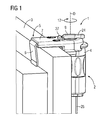
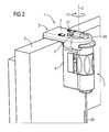
- FIG. 1 to FIG. 17 relate to the same embodiment of a clamp holder 1 according to the invention.
- FIG. 1 and FIG. 2 It is clear that the clamping bracket 1 for attachment of an object, here a cable tensioning device 2 for a sun and / or privacy protection, on a window or door frame 3 is used.
- a stretched with the rope tensioning device 2 rope 26 may, for example intended to guide a pleated blind, a blind or a curtain.
- the clamp holder comprising a clamping piece 4 and an elbow 5, wherein the clamping piece 4 comprises the cable tensioning device 2, that is, the rope tensioning device 2 is part of the clamping piece 4.
- the rope tensioning device 2 corresponds to the EP 2 329 747 A2 known rope tensioning device. For more information on their characteristics, please refer to this document.
- the angle piece 5 comprises a first leg 6 and a second leg 7, which enclose an angle 8.
- This angle 8 is not at 90 °, but at about 83 ° to enhance the clamping action.
- the first leg 6 of the elbow 5 made of metal, it is bent at the transition to the second leg 7 and locked by a metal nose 34 with the second leg 7.
- the second leg 7 and at least substantially the clamping part 2 may for example consist of plastic.
- the first leg 6 of the elbow 5 engages behind the window or door frame 3, the second leg 7 projects forward over the frame 3.
- the clamping piece 4 is slidably mounted on the second leg 7 of the elbow 5 along a longitudinal axis of the second leg 7 and for clamping the frame 3 between the second leg 7 of the elbow 5 and the clamping piece 4 to the frame 3 pressed.
- the clamping piece 4 parallel to the longitudinal axis of the second leg 7 of the elbow 5 extending lateral projections 17 on its second leg 7 facing upper side 28, which pass over a curved projection 30 on a side facing away from the first leg 6 end face 29 of the clamping piece 4 into each other ,
- the lateral projections 17 are guided by two guide rails 18, which are formed as undercut guide rails 18 on a clamping element 4 facing bottom 31 of the second leg 7 of the elbow 5 and with the lateral projections 17 correspond to such that they a guided linear displacement of the clamping piece 4 along the longitudinal axis of the second leg 7 of the elbow 5 allow.
- a rotary member 9 is rotatably mounted on or in the second leg 7 of the angle piece 5.
- a recess 19 corresponding to the rotary element 9 is provided in the second leg 7.
- This recess 19 has on its side wall a screening 20 which cooperates with a detent 21 on the rotary member 9.
- the rotary element 9 has an eccentric extension 10 on its underside 32 facing the clamping element 4.
- This eccentric extension 10 engages in a corresponding ExzenterausEnglishung 11 in the clamping piece 4 a.
- the clamping piece 4 Upon rotation of the rotary member 9 in a predetermined clamping direction of rotation 12 of the eccentric extension 10 presses the clamping piece 4 to the frame 3.
- the clamping piece 4 a Andschreibwand 14, which is oriented such that it faces away from the first leg 6 of the elbow 5, ie, when pressed against the Andschreibwand 14 of the clamping piece 4, the clamping piece 4 in the direction of the first leg 6 of the elbow 5 pressed.
- Areas of this pressing surface 13 press upon rotation of the rotary member 9 in clamping direction 12 against the Andschreibwand 14 of the clamping piece 4.
- the Andschreibwand 14 of the clamping piece 4 is a flat surface, the pressing surface 13 of the Exzenterfortsatzes 10 of the rotary member 9, however, is curved convexly, with a curvature which steadily, namely spirally decreases with increasing radial distance from the rotational axis D of the rotary member 9 ,
- the oppressive wall 14 pressing portion of the pressing surface 13 of the Exzenterfortsatzes 10 thereby migrates upon rotation of the rotary member 9 in the clamping direction 12 on the rotary member 9 radially outward.
- the rotary member 9 is rotatable between a clamping position 22 and a release position 23, wherein the clamping bracket 1 is clamped in the clamping position 22 of the rotary member 9 on the window or door frame 3 and in the release position 23 from the window or door frame 3 is removable.
- Decisive for the adoption of the clamping position 22 and the release position 23 is the position of the Exzenterfortsatzes 10 and thus the force exerted by him on the Andgurwand 14 force.
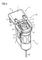
- FIG. 3 and FIG. 4 Therefore, in each case by omitting a view obstructing part of the second leg 6 and the rotary member 9, the position of the Exzenterfortsatzes 10th
- FIG. 3 shows the position of the Exzenterfortsatzes 10 in the release position 23 of the clamp 1
- FIG. 4 shows the position of the Exzenterfortsatzes 10 in the clamping position 22 of the clamping bracket. 1
- FIG. 3 It can be seen that the clamping piece 4 in the release position 23 from the first leg 6 of the elbow 5 is moved away until the Andschreibwand 14 abuts one of the pressing surface 13 opposite back 33 of the Exzenterfortsatzes 10, which is in the clamping direction 12 of the rotary member 11 behind.
- This back 33 of the Exzenterfortsatzes 10 is formed as a flat surface.
- FIG. 4 It can be seen that the clamping piece 4 is pressed in the clamping position 22 to the first leg 6 of the elbow 5, a portion of the pressing surface 13 of the Exzenterfortsatzes 10 presses against the Andschreibwand 14th
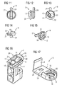
- FIG. 7 and FIG. 9 / FIG. 10 and so too 5 and FIG. 6 such as FIG. 8 show a position of the Exzenterfortsatzes 10 between the in FIG. 3 and FIG. 4 shown positions.
- the rotary member 9 has on its side opposite the Exzenterfortsatz 10 a handle 24 for manually carrying out a rotary movement of the rotary member 9, for example in Klemmformatraum 12 for clamping the clamp bracket 1 on the frame 3 or in the opposite direction to release the clamp bracket 1 from the frame 3 on ,
- the position of the handle 24 indicates to an operator the assumed position of the rotary member 9, in particular, the operator can thereby recognize whether the clamping bracket 1 is in the release position 23 or in the clamping position 22.
- the rotational movement of the rotary member 9 is limited by a stop 27 for the handle 24.
- the clamping direction of rotation 12 in plan view of the handle 24 is a rotary movement in the clockwise direction.
- stop position of the handle 24 on the stop 27 corresponds to the release position 23 of the clamping piece 4, it is indicated to the operator by a suitable symbol (open lock).
- the rotary member 9 is rotated to clamp the clamp bracket 1 on the frame 3 in the clamping direction 12 until the respective frame thickness corresponding clamping position 22 is reached.
- a maximum rotational movement is possible up to the position in which the handle 24 abuts against the opposite side of the stop 27. This position is indicated by a suitable symbol (closed lock). From the two symbols, the operator thus easily recognizes the direction of rotation of the rotary element 9 required for clamping or releasing the clamping holder 1.
- the eccentric extension can be pushed over the nose 25 with the pressure wall 14 away into the eccentric recess 11.
- the latching hook 16 allows this movement. After insertion of the Exzenterfortsatzes 10 in the ExzenterausEnglishung 11 moves the elastic latching hook 16, the nose 25 back to its original position, so that the Andschreibwand 14 at the nose 25 now prevents a new pushing out of the Exzenterfortsatzes 10 from the Exzenterausnaturalung 11.
Claims (7)
- Support de serrage (1) permettant de fixer un objet, en particulier un tendeur de câble (2) pour un dispositif de protection contre le soleil et/ou la vue, sur un cadre de fenêtre ou de porte (3), comportant une pièce de serrage (4) et une pièce coudée (5), ladite pièce de serrage (4) étant reliée ou pouvant être reliée à l'objet, en particulier le tendeur de câble (2), ou comportant ledit objet, en particulier le tendeur de câble (2), ladite pièce coudée (5) comportant une première branche (6) et une deuxième branche (7) qui forment un angle (8), ladite première branche (6) s'engageant derrière le cadre de fenêtre ou de porte (3) et la deuxième branche (7) s'avançant en saillie vers l'avant au-delà du cadre (3), et ladite pièce de serrage (4) étant montée mobile sur la deuxième branche (7) de la pièce coudée (5) et pouvant être pressée contre le cadre (3) pour enserrer le cadre (3) entre la deuxième branche (7) de la pièce coudée (5) et la pièce de serrage (4),
un élément rotatif (9) avec une saillie excentrée (10) étant monté rotatif dans et/ou sur la deuxième branche (7) de la pièce coudée (5),
ladite saillie excentrée (10) s'engageant dans un évidement excentré (11) correspondant dans la pièce de serrage (4), ladite saillie excentrée (10) pressant la pièce de serrage (4) contre le cadre (3) lorsque l'élément rotatif (9) tourne dans une direction de serrage (12) prédéfinie, et,
lorsque l'élément rotatif (9) tourne dans la direction de serrage (12), des zones d'une surface de pression (13) latérale, située à l'avant dans le sens de rotation, de la saillie excentrée (10) poussant contre une paroi d'appui (14) de la pièce de serrage (4), détournée de la première branche (6) de la pièce coudée (5), moyennant quoi la pièce de serrage (4) est pressée contre le cadre (3),
la pièce de serrage (4) pouvant se déplacer le long d'un axe longitudinal de la deuxième branche (7),
caractérisé en ce que la pièce de serrage (4) comporte des saillies (17) latérales, parallèles à l'axe longitudinal, lesquelles sont logées sur la deuxième branche (7) dans des rails de guidage (18) détalonnés, également parallèles à l'axe longitudinal. - Support de serrage selon la revendication 1, caractérisé en ce que la zone de la surface de pression (13), poussant contre la paroi d'appui (14), se déplace radialement vers l'extérieur sur l'élément rotatif (9) lorsque ledit élément rotatif (9) tourne dans la direction de serrage (12).
- Support de serrage selon la revendication 1 ou 2, caractérisé en ce que la paroi d'appui (14) est sensiblement plane et/ou la surface de pression (13) possède une courbure sensiblement convexe, en particulier une courbure qui diminue en s'écartant radialement de l'axe de rotation (D) de l'élément rotatif (9), de préférence qui diminue en continu et/ou en spirale.
- Support de serrage selon l'une quelconque des revendications précédentes, caractérisé
en ce que l'évidement excentré (11) de la pièce de serrage (4) comporte, au niveau de son côté orienté vers la première branche (6) de la pièce coudée (5), une ouverture (15) pour insérer la saillie excentrée (10) dans l'évidement excentré (11) au moment de l'assemblage du support de serrage (1) par le rapprochement de la pièce de serrage (4) et de la pièce coudée (5), et
en ce que la paroi d'appui (14) est réalisée sur un taquet (25) d'un crochet de blocage (16), lequel taquet est disposé dans l'évidement excentré (11) et peut être enfoncé élastiquement et lequel est agencé et réalisé de telle sorte que, lorsque la saillie excentrée (10) est introduite dans l'évidement excentré (11), ledit taquet, compte tenu de sa conception en forme de cale, est enfoncé par la saillie excentrée (10) plus profondément dans l'évidement excentré (11) et, de ce fait, permet l'introduction de la saillie excentrée (10) dans l'évidement excentré (11), néanmoins revient dans sa position initiale après l'introduction de la saillie excentrée (10) et, en raison de la paroi d'appui (14), empêche dans cette position que la saillie excentrée (10) puisse s'extraire à nouveau de l'évidement excentré (11). - Support de serrage selon l'une quelconque des revendications précédentes, caractérisé en ce que l'élément rotatif (9) est monté rotatif dans un évidement (19) correspondant dans la deuxième branche (7) de la pièce coudée (5), en particulier dans un évidement (19) qui comporte une surface à crans de blocage (20) qui correspondent à un ou plusieurs ergots de blocage (21) sur l'élément rotatif (9).
- Support de serrage selon l'une quelconque des revendications précédentes, caractérisé en ce que l'élément rotatif (9) est apte à tourner entre une position de blocage (22) et une position de déblocage (23), ledit support de serrage (1) étant immobilisé contre le cadre de fenêtre ou de porte (3) dans la position de blocage (22) de l'élément rotatif (9) et pouvant être détaché du cadre de fenêtre ou de porte (3) dans une position de déblocage (23).
- Support de serrage selon l'une quelconque des revendications précédentes, caractérisé en ce que l'élément rotatif (9), au niveau de son côté en regard de la saillie excentrée (10), comporte une poignée (24) permettant d'effectuer manuellement un mouvement de rotation de l'élément rotatif (9), dont la position indique à un utilisateur la position prise par l'élément rotatif (9).
Priority Applications (1)
| Application Number | Priority Date | Filing Date | Title |
|---|---|---|---|
| EP20110189733 EP2594165B1 (fr) | 2011-11-18 | 2011-11-18 | Support pour la fixation par serrage d'un objet, notamment d'un dispositif de tensionnement d'un cable pour un dispositif de pare-soleil et/ou de protection contre la vue, sur un cadre de fenêtre ou de porte |
Applications Claiming Priority (1)
| Application Number | Priority Date | Filing Date | Title |
|---|---|---|---|
| EP20110189733 EP2594165B1 (fr) | 2011-11-18 | 2011-11-18 | Support pour la fixation par serrage d'un objet, notamment d'un dispositif de tensionnement d'un cable pour un dispositif de pare-soleil et/ou de protection contre la vue, sur un cadre de fenêtre ou de porte |
Publications (2)
| Publication Number | Publication Date |
|---|---|
| EP2594165A1 EP2594165A1 (fr) | 2013-05-22 |
| EP2594165B1 true EP2594165B1 (fr) | 2013-08-28 |
Family
ID=45092241
Family Applications (1)
| Application Number | Title | Priority Date | Filing Date |
|---|---|---|---|
| EP20110189733 Not-in-force EP2594165B1 (fr) | 2011-11-18 | 2011-11-18 | Support pour la fixation par serrage d'un objet, notamment d'un dispositif de tensionnement d'un cable pour un dispositif de pare-soleil et/ou de protection contre la vue, sur un cadre de fenêtre ou de porte |
Country Status (1)
| Country | Link |
|---|---|
| EP (1) | EP2594165B1 (fr) |
Families Citing this family (3)
| Publication number | Priority date | Publication date | Assignee | Title |
|---|---|---|---|---|
| EP3189754B1 (fr) * | 2016-01-08 | 2018-06-06 | Inventex Establishment | Support de fixation d'un dispositif pare-soleil et/ou pare-vue sur un cadre de porte ou de fenêtre |
| DE102017112247A1 (de) * | 2017-06-02 | 2018-12-06 | Windhager Handelsgesmbh | Klemmmechanismus für Profil-Rahmensystem |
| US11352824B2 (en) | 2020-05-27 | 2022-06-07 | Hi-Lex Controls, Inc. | Cable guide assembly for a window regulator |
Family Cites Families (5)
| Publication number | Priority date | Publication date | Assignee | Title |
|---|---|---|---|---|
| US1772621A (en) * | 1927-10-08 | 1930-08-12 | William C Wofford | Window-shade support |
| EP0081277B1 (fr) * | 1981-08-05 | 1987-11-19 | James Pert | Connecteur avec moyen de serrage |
| DE29503342U1 (de) | 1995-02-28 | 1995-04-13 | Henning Wolfgang | Universal-Montageprofil zum Anklemmen |
| DE19636921C1 (de) | 1996-09-11 | 1998-03-12 | Gerd Liese | Klemmhalterung für das Trägerelement einer Sonnen- oder Blickschutzeinrichtung |
| CH701983A1 (de) | 2009-10-14 | 2011-04-15 | Inventex Establishment | Spannvorrichtung für Vorhangseil. |
-
2011
- 2011-11-18 EP EP20110189733 patent/EP2594165B1/fr not_active Not-in-force
Also Published As
| Publication number | Publication date |
|---|---|
| EP2594165A1 (fr) | 2013-05-22 |
Similar Documents
| Publication | Publication Date | Title |
|---|---|---|
| DE60304318T2 (de) | Befestigung einer rohrklemme | |
| DE202007008610U1 (de) | Befestigungssystem | |
| EP2876238B1 (fr) | Élément de réception pour un châssis en acier et châssis en acier en étant équipé | |
| EP2536958A1 (fr) | Dispositif de fixation | |
| EP3633131B1 (fr) | Élément de cadre | |
| EP2594165B1 (fr) | Support pour la fixation par serrage d'un objet, notamment d'un dispositif de tensionnement d'un cable pour un dispositif de pare-soleil et/ou de protection contre la vue, sur un cadre de fenêtre ou de porte | |
| EP1960220A1 (fr) | Coupleur de store pour un store de toit ouvrant de véhicule, et bande de store, et store de toit ouvrant de véhicule | |
| DE102009050159A1 (de) | Montagevorrichtung für eine Einbauleuchte | |
| DE202011052021U1 (de) | Klemmhalterung zur Befestigung eines Objekts, insbesondere einer Seilspannvorrichtung für einen Sonnen- und/oder Blickschutzvorrichtung, an einem Fenster- oder Türrahmen | |
| DE202010007139U1 (de) | Vorrichtung zur Befestigung eines Moduls zur Nutzung von Sonnenenergie | |
| WO2008092585A1 (fr) | Unité de fixation comprenant un élément de fixation pouvant être attaché au niveau d'un élément de support | |
| DE10029102B4 (de) | Vorrichtung zum Befestigen einer Leuchte | |
| EP3336275B1 (fr) | Dispositif de fixation de toile et dispositif de guidage | |
| EP3535824B1 (fr) | Support de jeu de barres et ensemble correspondant | |
| DE102012104863B3 (de) | Türbandanordnung mit einem Türband und einem Aufnahmeelement | |
| DE102010047991A1 (de) | Befestigungssystem eines Kabelübergangsgerätes in einem Mast | |
| DE202016103609U1 (de) | Adapter zur Montage an einem Fixpunkt eines Fahrzeugs | |
| DE102005057589B4 (de) | Spannbügel | |
| DE202008007345U1 (de) | Scharniertopf für Möbelscharniere | |
| DE102013112761A1 (de) | Haltevorrichtung für ein Gehäuse und Verfahren zur Montage des Gehäuses unter Verwendung der Haltevorrichtung | |
| DE102020126347B3 (de) | Abstandhalter, Führungsschiene für einen Raffstore oder eine Jalousie sowie Raffstore und Jalousie und Verfahren hierfür | |
| DE202010004995U1 (de) | Befestiger zur Befestigung eines ersten Bauteils an einem zweiten Bauteil | |
| DE202010006532U1 (de) | Rastscharnier | |
| DE202009010957U1 (de) | Montageaufbau eines teleskopischen Schutzdeckels | |
| DE102011101759A1 (de) | Vorrichtung zur Montage eines Schalters oder dergleichen an einer Montageplatte |
Legal Events
| Date | Code | Title | Description |
|---|---|---|---|
| GRAP | Despatch of communication of intention to grant a patent |
Free format text: ORIGINAL CODE: EPIDOSNIGR1 |
|
| PUAI | Public reference made under article 153(3) epc to a published international application that has entered the european phase |
Free format text: ORIGINAL CODE: 0009012 |
|
| 17P | Request for examination filed |
Effective date: 20120705 |
|
| AK | Designated contracting states |
Kind code of ref document: A1 Designated state(s): AL AT BE BG CH CY CZ DE DK EE ES FI FR GB GR HR HU IE IS IT LI LT LU LV MC MK MT NL NO PL PT RO RS SE SI SK SM TR |
|
| AX | Request for extension of the european patent |
Extension state: BA ME |
|
| GRAS | Grant fee paid |
Free format text: ORIGINAL CODE: EPIDOSNIGR3 |
|
| GRAA | (expected) grant |
Free format text: ORIGINAL CODE: 0009210 |
|
| AK | Designated contracting states |
Kind code of ref document: B1 Designated state(s): AL AT BE BG CH CY CZ DE DK EE ES FI FR GB GR HR HU IE IS IT LI LT LU LV MC MK MT NL NO PL PT RO RS SE SI SK SM TR |
|
| REG | Reference to a national code |
Ref country code: GB Ref legal event code: FG4D Free format text: NOT ENGLISH |
|
| REG | Reference to a national code |
Ref country code: CH Ref legal event code: EP |
|
| REG | Reference to a national code |
Ref country code: AT Ref legal event code: REF Ref document number: 628821 Country of ref document: AT Kind code of ref document: T Effective date: 20130915 |
|
| REG | Reference to a national code |
Ref country code: IE Ref legal event code: FG4D Free format text: LANGUAGE OF EP DOCUMENT: GERMAN |
|
| REG | Reference to a national code |
Ref country code: DE Ref legal event code: R096 Ref document number: 502011001252 Country of ref document: DE Effective date: 20131024 |
|
| REG | Reference to a national code |
Ref country code: CH Ref legal event code: NV Representative=s name: FIAMMENGHI-FIAMMENGHI, CH |
|
| REG | Reference to a national code |
Ref country code: LT Ref legal event code: MG4D |
|
| REG | Reference to a national code |
Ref country code: NL Ref legal event code: VDEP Effective date: 20130828 |
|
| PG25 | Lapsed in a contracting state [announced via postgrant information from national office to epo] |
Ref country code: PT Free format text: LAPSE BECAUSE OF FAILURE TO SUBMIT A TRANSLATION OF THE DESCRIPTION OR TO PAY THE FEE WITHIN THE PRESCRIBED TIME-LIMIT Effective date: 20131230 Ref country code: LT Free format text: LAPSE BECAUSE OF FAILURE TO SUBMIT A TRANSLATION OF THE DESCRIPTION OR TO PAY THE FEE WITHIN THE PRESCRIBED TIME-LIMIT Effective date: 20130828 Ref country code: NO Free format text: LAPSE BECAUSE OF FAILURE TO SUBMIT A TRANSLATION OF THE DESCRIPTION OR TO PAY THE FEE WITHIN THE PRESCRIBED TIME-LIMIT Effective date: 20131128 Ref country code: CY Free format text: LAPSE BECAUSE OF FAILURE TO SUBMIT A TRANSLATION OF THE DESCRIPTION OR TO PAY THE FEE WITHIN THE PRESCRIBED TIME-LIMIT Effective date: 20130918 Ref country code: SE Free format text: LAPSE BECAUSE OF FAILURE TO SUBMIT A TRANSLATION OF THE DESCRIPTION OR TO PAY THE FEE WITHIN THE PRESCRIBED TIME-LIMIT Effective date: 20130828 Ref country code: IS Free format text: LAPSE BECAUSE OF FAILURE TO SUBMIT A TRANSLATION OF THE DESCRIPTION OR TO PAY THE FEE WITHIN THE PRESCRIBED TIME-LIMIT Effective date: 20131228 Ref country code: HR Free format text: LAPSE BECAUSE OF FAILURE TO SUBMIT A TRANSLATION OF THE DESCRIPTION OR TO PAY THE FEE WITHIN THE PRESCRIBED TIME-LIMIT Effective date: 20130828 |
|
| REG | Reference to a national code |
Ref country code: NL Ref legal event code: VDEP Effective date: 20130828 |
|
| PG25 | Lapsed in a contracting state [announced via postgrant information from national office to epo] |
Ref country code: PL Free format text: LAPSE BECAUSE OF FAILURE TO SUBMIT A TRANSLATION OF THE DESCRIPTION OR TO PAY THE FEE WITHIN THE PRESCRIBED TIME-LIMIT Effective date: 20130828 Ref country code: GR Free format text: LAPSE BECAUSE OF FAILURE TO SUBMIT A TRANSLATION OF THE DESCRIPTION OR TO PAY THE FEE WITHIN THE PRESCRIBED TIME-LIMIT Effective date: 20131129 Ref country code: FI Free format text: LAPSE BECAUSE OF FAILURE TO SUBMIT A TRANSLATION OF THE DESCRIPTION OR TO PAY THE FEE WITHIN THE PRESCRIBED TIME-LIMIT Effective date: 20130828 Ref country code: LV Free format text: LAPSE BECAUSE OF FAILURE TO SUBMIT A TRANSLATION OF THE DESCRIPTION OR TO PAY THE FEE WITHIN THE PRESCRIBED TIME-LIMIT Effective date: 20130828 |
|
| PG25 | Lapsed in a contracting state [announced via postgrant information from national office to epo] |
Ref country code: CY Free format text: LAPSE BECAUSE OF FAILURE TO SUBMIT A TRANSLATION OF THE DESCRIPTION OR TO PAY THE FEE WITHIN THE PRESCRIBED TIME-LIMIT Effective date: 20130828 |
|
| PG25 | Lapsed in a contracting state [announced via postgrant information from national office to epo] |
Ref country code: CZ Free format text: LAPSE BECAUSE OF FAILURE TO SUBMIT A TRANSLATION OF THE DESCRIPTION OR TO PAY THE FEE WITHIN THE PRESCRIBED TIME-LIMIT Effective date: 20130828 Ref country code: EE Free format text: LAPSE BECAUSE OF FAILURE TO SUBMIT A TRANSLATION OF THE DESCRIPTION OR TO PAY THE FEE WITHIN THE PRESCRIBED TIME-LIMIT Effective date: 20130828 Ref country code: DK Free format text: LAPSE BECAUSE OF FAILURE TO SUBMIT A TRANSLATION OF THE DESCRIPTION OR TO PAY THE FEE WITHIN THE PRESCRIBED TIME-LIMIT Effective date: 20130828 Ref country code: RO Free format text: LAPSE BECAUSE OF FAILURE TO SUBMIT A TRANSLATION OF THE DESCRIPTION OR TO PAY THE FEE WITHIN THE PRESCRIBED TIME-LIMIT Effective date: 20130828 Ref country code: NL Free format text: LAPSE BECAUSE OF FAILURE TO SUBMIT A TRANSLATION OF THE DESCRIPTION OR TO PAY THE FEE WITHIN THE PRESCRIBED TIME-LIMIT Effective date: 20130828 Ref country code: SK Free format text: LAPSE BECAUSE OF FAILURE TO SUBMIT A TRANSLATION OF THE DESCRIPTION OR TO PAY THE FEE WITHIN THE PRESCRIBED TIME-LIMIT Effective date: 20130828 |
|
| PG25 | Lapsed in a contracting state [announced via postgrant information from national office to epo] |
Ref country code: IT Free format text: LAPSE BECAUSE OF FAILURE TO SUBMIT A TRANSLATION OF THE DESCRIPTION OR TO PAY THE FEE WITHIN THE PRESCRIBED TIME-LIMIT Effective date: 20130828 Ref country code: ES Free format text: LAPSE BECAUSE OF FAILURE TO SUBMIT A TRANSLATION OF THE DESCRIPTION OR TO PAY THE FEE WITHIN THE PRESCRIBED TIME-LIMIT Effective date: 20130828 |
|
| REG | Reference to a national code |
Ref country code: DE Ref legal event code: R097 Ref document number: 502011001252 Country of ref document: DE |
|
| BERE | Be: lapsed |
Owner name: INVENTEX ESTABLISHMENT Effective date: 20131130 |
|
| PLBE | No opposition filed within time limit |
Free format text: ORIGINAL CODE: 0009261 |
|
| STAA | Information on the status of an ep patent application or granted ep patent |
Free format text: STATUS: NO OPPOSITION FILED WITHIN TIME LIMIT |
|
| PG25 | Lapsed in a contracting state [announced via postgrant information from national office to epo] |
Ref country code: MC Free format text: LAPSE BECAUSE OF FAILURE TO SUBMIT A TRANSLATION OF THE DESCRIPTION OR TO PAY THE FEE WITHIN THE PRESCRIBED TIME-LIMIT Effective date: 20130828 |
|
| 26N | No opposition filed |
Effective date: 20140530 |
|
| REG | Reference to a national code |
Ref country code: IE Ref legal event code: MM4A |
|
| REG | Reference to a national code |
Ref country code: DE Ref legal event code: R097 Ref document number: 502011001252 Country of ref document: DE Effective date: 20140530 |
|
| PG25 | Lapsed in a contracting state [announced via postgrant information from national office to epo] |
Ref country code: BE Free format text: LAPSE BECAUSE OF NON-PAYMENT OF DUE FEES Effective date: 20131130 |
|
| PG25 | Lapsed in a contracting state [announced via postgrant information from national office to epo] |
Ref country code: IE Free format text: LAPSE BECAUSE OF NON-PAYMENT OF DUE FEES Effective date: 20131118 |
|
| PG25 | Lapsed in a contracting state [announced via postgrant information from national office to epo] |
Ref country code: SM Free format text: LAPSE BECAUSE OF FAILURE TO SUBMIT A TRANSLATION OF THE DESCRIPTION OR TO PAY THE FEE WITHIN THE PRESCRIBED TIME-LIMIT Effective date: 20130828 |
|
| REG | Reference to a national code |
Ref country code: CH Ref legal event code: PL |
|
| PG25 | Lapsed in a contracting state [announced via postgrant information from national office to epo] |
Ref country code: RS Free format text: LAPSE BECAUSE OF FAILURE TO SUBMIT A TRANSLATION OF THE DESCRIPTION OR TO PAY THE FEE WITHIN THE PRESCRIBED TIME-LIMIT Effective date: 20131128 Ref country code: SI Free format text: LAPSE BECAUSE OF NON-PAYMENT OF DUE FEES Effective date: 20140110 Ref country code: HU Free format text: LAPSE BECAUSE OF FAILURE TO SUBMIT A TRANSLATION OF THE DESCRIPTION OR TO PAY THE FEE WITHIN THE PRESCRIBED TIME-LIMIT; INVALID AB INITIO Effective date: 20111118 Ref country code: MK Free format text: LAPSE BECAUSE OF FAILURE TO SUBMIT A TRANSLATION OF THE DESCRIPTION OR TO PAY THE FEE WITHIN THE PRESCRIBED TIME-LIMIT Effective date: 20130828 Ref country code: CH Free format text: LAPSE BECAUSE OF NON-PAYMENT OF DUE FEES Effective date: 20141130 Ref country code: BG Free format text: LAPSE BECAUSE OF FAILURE TO SUBMIT A TRANSLATION OF THE DESCRIPTION OR TO PAY THE FEE WITHIN THE PRESCRIBED TIME-LIMIT Effective date: 20130828 Ref country code: LU Free format text: LAPSE BECAUSE OF NON-PAYMENT OF DUE FEES Effective date: 20131118 Ref country code: LI Free format text: LAPSE BECAUSE OF NON-PAYMENT OF DUE FEES Effective date: 20141130 |
|
| PG25 | Lapsed in a contracting state [announced via postgrant information from national office to epo] |
Ref country code: MT Free format text: LAPSE BECAUSE OF FAILURE TO SUBMIT A TRANSLATION OF THE DESCRIPTION OR TO PAY THE FEE WITHIN THE PRESCRIBED TIME-LIMIT Effective date: 20130828 |
|
| REG | Reference to a national code |
Ref country code: FR Ref legal event code: PLFP Year of fee payment: 5 |
|
| PGFP | Annual fee paid to national office [announced via postgrant information from national office to epo] |
Ref country code: FR Payment date: 20151127 Year of fee payment: 5 |
|
| GBPC | Gb: european patent ceased through non-payment of renewal fee |
Effective date: 20151118 |
|
| PG25 | Lapsed in a contracting state [announced via postgrant information from national office to epo] |
Ref country code: TR Free format text: LAPSE BECAUSE OF FAILURE TO SUBMIT A TRANSLATION OF THE DESCRIPTION OR TO PAY THE FEE WITHIN THE PRESCRIBED TIME-LIMIT Effective date: 20130828 |
|
| PG25 | Lapsed in a contracting state [announced via postgrant information from national office to epo] |
Ref country code: GB Free format text: LAPSE BECAUSE OF NON-PAYMENT OF DUE FEES Effective date: 20151118 |
|
| REG | Reference to a national code |
Ref country code: FR Ref legal event code: ST Effective date: 20170731 |
|
| PG25 | Lapsed in a contracting state [announced via postgrant information from national office to epo] |
Ref country code: FR Free format text: LAPSE BECAUSE OF NON-PAYMENT OF DUE FEES Effective date: 20161130 |
|
| REG | Reference to a national code |
Ref country code: AT Ref legal event code: MM01 Ref document number: 628821 Country of ref document: AT Kind code of ref document: T Effective date: 20161118 |
|
| PG25 | Lapsed in a contracting state [announced via postgrant information from national office to epo] |
Ref country code: AT Free format text: LAPSE BECAUSE OF NON-PAYMENT OF DUE FEES Effective date: 20161118 |
|
| PG25 | Lapsed in a contracting state [announced via postgrant information from national office to epo] |
Ref country code: AL Free format text: LAPSE BECAUSE OF FAILURE TO SUBMIT A TRANSLATION OF THE DESCRIPTION OR TO PAY THE FEE WITHIN THE PRESCRIBED TIME-LIMIT Effective date: 20130828 |
|
| PGFP | Annual fee paid to national office [announced via postgrant information from national office to epo] |
Ref country code: DE Payment date: 20181204 Year of fee payment: 8 |
|
| REG | Reference to a national code |
Ref country code: DE Ref legal event code: R119 Ref document number: 502011001252 Country of ref document: DE |
|
| PG25 | Lapsed in a contracting state [announced via postgrant information from national office to epo] |
Ref country code: DE Free format text: LAPSE BECAUSE OF NON-PAYMENT OF DUE FEES Effective date: 20200603 |