EP2592966B1 - Ausziehführung für schubladen - Google Patents
Ausziehführung für schubladen Download PDFInfo
- Publication number
- EP2592966B1 EP2592966B1 EP11710725.0A EP11710725A EP2592966B1 EP 2592966 B1 EP2592966 B1 EP 2592966B1 EP 11710725 A EP11710725 A EP 11710725A EP 2592966 B1 EP2592966 B1 EP 2592966B1
- Authority
- EP
- European Patent Office
- Prior art keywords
- rail
- pull
- drawer
- automatic retraction
- out guide
- Prior art date
- Legal status (The legal status is an assumption and is not a legal conclusion. Google has not performed a legal analysis and makes no representation as to the accuracy of the status listed.)
- Active
Links
Images


Classifications
-
- A—HUMAN NECESSITIES
- A47—FURNITURE; DOMESTIC ARTICLES OR APPLIANCES; COFFEE MILLS; SPICE MILLS; SUCTION CLEANERS IN GENERAL
- A47B—TABLES; DESKS; OFFICE FURNITURE; CABINETS; DRAWERS; GENERAL DETAILS OF FURNITURE
- A47B88/00—Drawers for tables, cabinets or like furniture; Guides for drawers
- A47B88/40—Sliding drawers; Slides or guides therefor
- A47B88/453—Actuated drawers
- A47B88/46—Actuated drawers operated by mechanically-stored energy, e.g. by springs
- A47B88/467—Actuated drawers operated by mechanically-stored energy, e.g. by springs self-closing
-
- A—HUMAN NECESSITIES
- A47—FURNITURE; DOMESTIC ARTICLES OR APPLIANCES; COFFEE MILLS; SPICE MILLS; SUCTION CLEANERS IN GENERAL
- A47B—TABLES; DESKS; OFFICE FURNITURE; CABINETS; DRAWERS; GENERAL DETAILS OF FURNITURE
- A47B2210/00—General construction of drawers, guides and guide devices
- A47B2210/0091—Drawer movement damping
- A47B2210/0094—Drawer damping device with 2 relatively movable parts to convert kinetic energy
-
- A—HUMAN NECESSITIES
- A47—FURNITURE; DOMESTIC ARTICLES OR APPLIANCES; COFFEE MILLS; SPICE MILLS; SUCTION CLEANERS IN GENERAL
- A47B—TABLES; DESKS; OFFICE FURNITURE; CABINETS; DRAWERS; GENERAL DETAILS OF FURNITURE
- A47B88/00—Drawers for tables, cabinets or like furniture; Guides for drawers
- A47B88/40—Sliding drawers; Slides or guides therefor
- A47B88/49—Sliding drawers; Slides or guides therefor with double extensible guides or parts
Definitions
- the invention relates to a pull-out for drawers or the like.
- a carcass rail With a carcass rail, with a drawer rail and a self-closing pull the drawer rail in its closed end position, the self-closing is attached to the carcass or drawer rail and a longitudinally displaceable guided, tiltable coupling element has, which cooperates with a provided on the other rail driver.
- drawers for drawers are known in which the self-closing is arranged horizontally next to the rail guide package.
- this additional space is needed in addition to the rail guide package, so that the apron of the goods carrier must be designed to be large enough to cover the Diseinzugsmechanik also.
- pull-out guides are known in which the self-closing mechanism is arranged between the drawer rail and the carcase rail, i. is integrated into the rail guide package, and the triggering kinematics of the self-closing is triggered horizontally.
- this horizontal tripping kinematics has the disadvantage that the self-closing housing must be made relatively stiff and often protrudes laterally from the guide package. This results in the goods carrier often a noticeable lateral release movement, since the release force acts in the direction of the weaker area moment of inertia of the guide package.
- elaborate Deinzugsgepurkonstruktionen made of sheet metal to absorb the resulting lateral tripping forces. Even with these solutions, the coupling mechanism often protrudes horizontally from the guide package.
- pullout guides are known in which the self-closing is arranged in the carcass or the drawer rail. Since this area can not then be used as a guideway, in these solutions, the self-retraction can therefore only be arranged in extension of the rails, which has the use of longer, more expensive rails result. In the arrangement in the carcass rail also no short guide versions are possible.
- This object is achieved in that the self-closing and the driver are arranged in a vertical space formed between a horizontal web of the carcass rail and a horizontal web of the drawer rail that the self-closing housing rests against the horizontal web of that rail to which the self-closing is attached , And that the coupling element is tiltable about a horizontal axis in a locking position.
- the inventive support of the self-closing housing on the horizontal web of the carcass or drawer rail allows a particularly compact and filigree integration of Double-coupling between carcass and drawer rail, since the vertical coupling and decoupling of the coupling element resulting vertical coupling or decoupling forces on the carcass or Drawer rail can be derived.
- the drawer load vertically receivable by these rails is much larger than the horizontally absorbable forces.
- the coupling-in or coupling-out forces which occur are taken up vertically in the direction of the higher load-bearing capacity of the rail guide and introduced there barely noticeably into the guide package.
- the vertical game in the leadership package is much lower than the horizontal game.
- the compact design also makes it possible to cover the guide package with a hollow chamber frame / goods carrier / drawer to the very bottom of the wall bracket.
- the self-closing housing is preferably located on the horizontal web at least in the two end positions of the coupling element.
- the coupling element rests in its cocked tilted end position inside of that housing wall of the self-closing housing, with which the self-closing housing rests on the outside of the horizontal web.
- Pull-out guide 1 shown for a drawer comprises a carcass rail 2, a drawer rail 3 and a middle rail running between the two .
- the rails 2, 3, 4 are guided by rolling elements (not shown) relative to each other in the longitudinal direction displaceable.
- the rolling elements are rotatably mounted within WälzSystemurafigen of two WälzSystemwagen (not shown), of which the lower WälzSystemwagen is mounted in the carcass rail 2 and the upper WälzSystemwagen in the drawer rail 3.
- On the carcass rail 2 two body legs 5 are provided for attachment to a furniture body.
- the entire guide package from the rails 2, 3, 4 and their guides is in Fig. 2 denoted by 6 .
- a built-in guide package 6 self-closing 10 is attached, which absorbs the drawer rail 3 damped just before its closed end position in this end position.
- the self-closing 10 has a longitudinally displaceably guided, tiltable coupling element 11 which is guided in a guide of the self-closing housing 12 and cooperates with a provided on the carcass rail 2 driver 13 , and a linear damper 14 for damping the retraction movement.
- the self-retraction 10 and the driver 13 are arranged in a vertical gap 15 which is formed between a horizontal web 2a of the carcass rail 2 and a horizontal web 3a of the drawer rail 3.
- the self-closing housing 12 rests on its entire length, ie in particular on the entire displacement path of the coupling element 11, with the upper housing wall at the bottom of the horizontal web 3a of the drawer rail 3.
- the linear damper 14 is located with its top down on the horizontal web 3a of the drawer rail 3.
- FIGS. 3a, 3b the drawer rail 3 is shown in its closed end position with retracted self-closing 10, wherein the driver 13 engages in a recess of the hook-shaped coupling element 11.
- a catch spring (not shown) longitudinally displaced until it tilts at the end of the guide track about a horizontal axis 16 in a locked position and thereby decoupled from the driver 13.
- the drawer rail 3 with the now tensioned self-closing 10 can be pulled out freely to its open end position.
- the coupling element 11 is located on the inside of that housing wall with which the self-closing housing 12 abuts the outside of the horizontal web 3a.
- the driver 13 again engages in the recess of the coupling element 11 shortly before its closed end position and begins to rotate the coupling element 11 out of its locking position.
- the pull-in spring pulls the coupling element 11, which is held on the driver 13, and thus the drawer rail 3 ( FIGS. 4a, 4b ), whereby the drawer rail 3 - damped by the linear damper 14 - is brought into the fully retracted position.
- the self-closing housing 12 together with the linear damper 14 rests on the horizontal web 3a of the drawer rail 3 and the coupling element 11 abuts in its cocked tilted end position on Diseinzugsgephase 12, the vertical input or Auskoppel concept generated by the feed spring during tilting of the coupling element 11 directly to the drawer rail 3 derived.
- the drawer rail 3 is designed on the one hand for receiving high vertical drawer loads, and on the other hand, the vertically from the drawer rail 3 recordable drawer load is much larger than the horizontally absorbable forces.
- the incoming or decoupling forces of the coupling element 11 are received vertically in the direction of the higher load bearing of the rail guide and introduced there barely noticeable in the guide package 6.
- pull-out 1 is formed due to their center rail 4 for a full extension of the drawer, which is in FIGS. 5 and 6 shown pull-out 1, which has no center rail, formed only for a partial extension of the drawer.
- the drawer rail 3 is guided directly in the carcass rail 2, and the horizontal web 2a of the carcass rail 2 is formed by a bent tab of the carcass rail 2, on which the driver 13 is attached.
Landscapes
- Engineering & Computer Science (AREA)
- Mechanical Engineering (AREA)
- Drawers Of Furniture (AREA)
Description
- Die Erfindung betrifft eine Ausziehführung für Schubladen oder dgl. mit einer Korpusschiene, mit einer Schubladenschiene und mit einem Selbsteinzug zum Einziehen der Schubladenschiene in ihre geschlossene Endstellung, wobei der Selbsteinzug an der Korpus- oder an der Schubladenschiene befestigt ist und ein längsverschiebbar geführtes, verkippbares Kopplungselement aufweist, das mit einem an der jeweils anderen Schiene vorgesehenen Mitnehmer zusammenwirkt.
- Es sind Ausziehführungen für Schubladen bekannt, bei denen der Selbsteinzug horizontal neben dem Schienenführungspaket angeordnet ist. Allerdings wird hierbei zusätzlicher Platz neben dem Schienenführungspaket benötigt, so dass die Schürze des Warenträgers entsprechend groß ausgelegt werden muss, um die Selbsteinzugsmechanik ebenfalls zu überdecken.
- Auch sind Ausziehführungen bekannt, bei denen der Selbsteinzug zwischen Schubladen- und Korpusschiene angeordnet ist, d.h. in das Schienenführungspaket integriert ist, und die Auslösekinematik des Selbsteinzugs horizontal ausgelöst wird. Diese horizontale Auslösekinematik hat allerdings den Nachteil, dass das Selbsteinzugsgehäuse relativ steif ausgeführt werden muss und oft seitlich aus dem Führungspaket absteht. Hierbei entsteht am Warenträger oft eine spürbare seitliche Auslösebewegung, da die Auslösekraft in Richtung des schwächeren Flächenträgheitsmomentes des Führungspaketes wirkt. Auch bekannt sind aufwändige Selbsteinzugsgehäusekonstruktionen aus Blech, um die entstehenden seitlichen Auslösekräfte aufzufangen. Auch bei diesen Lösungen ragt die Kopplungsmechanik oft horizontal aus dem Führungspaket vor.
- Weiterhin sind auch Ausziehführungen bekannt, bei denen der Selbsteinzug in der Korpus- oder der Schubladenschiene angeordnet ist. Da dieser Bereich dann nicht als Führungsbahn benutzt werden kann, kann bei diesen Lösungen der Selbsteinzug also nur in Verlängerung der Schienen angeordnet werden, was den Einsatz von längeren, teureren Schienen zur Folge hat. Bei der Anordnung in der Korpusschiene sind zudem keine kurzen Führungsversionen möglich.
- Ein Beispiel von einer Ausziehführung mit einem Selbsteinzug ist aus der veröffentliche
Patent US 7,040,725 B1 zu entnehmen. - Demgegenüber ist es die Aufgabe der vorliegenden Erfindung, bei einer Ausziehführung der eingangs genannten Art diese Nachteile zu beheben.
- Diese Aufgabe wird erfindungsgemäß dadurch gelöst, dass der Selbsteinzug und der Mitnehmer in einem vertikalen Zwischenraum angeordnet sind, der zwischen einem Horizontalsteg der Korpusschiene und einem Horizontalsteg der Schubladenschiene gebildet ist, dass das Selbsteinzugsgehäuse an dem Horizontalsteg derjenigen Schiene anliegt, an der der Selbsteinzug befestigt ist, und dass das Kopplungselement um eine horizontale Achse in eine Arretierstellung verkippbar ist.
- Die erfindungsgemäße Abstützung des Selbsteinzugsgehäuses am Horizontalsteg der Korpus- oder der Schubladenschiene ermöglicht eine besonders kompakte und filigrane Integration des Selbsteinzugs zwischen Korpus- und Schubladenschiene, da die beim vertikalen Ein- und Auskoppeln des Kopplungselements entstehenden vertikalen Einkoppel- bzw. Auskoppelkräfte auf die Korpus- bzw. Schubladenschiene abgeleitet werden. Die von diesen Schienen vertikal aufnehmbare Schubladenlast ist viel größer als die horizontal aufnehmbaren Kräfte. Die auftretenden Einkoppel- bzw. Auskoppelkräfte werden erfindungsgemäß vertikal in Richtung der höheren Lastaufnahme der Schienenführung aufgenommen und dort kaum merklich in das Führungspaket eingeleitet. Zudem ist das vertikale Spiel im Führungspaket wesentlich geringer als das horizontale Spiel. Die kompakte Bauweise ermöglicht auch das Verdecken des Führungspaketes mit Hohlkammerzarge/Warenträger/Schublade bis tief zum Wandbügel hin.
- Zur optimalen Aufnahme der Einkoppel- bzw. Auskoppelkräfte des Kopplungselements liegt das Selbsteinzugsgehäuse vorzugsweise zumindest in den beiden Endpositionen des Kopplungselements am Horizontalsteg an.
- Besonders bevorzugt liegt dass Kopplungselement in seiner gespannten verkippten Endstellung innen an derjenigen Gehäusewand des Selbsteinzugsgehäuses anliegt, mit der das Selbsteinzugsgehäuse außen am Horizontalsteg anliegt.
- Weitere Vorteile der Erfindung ergeben sich aus der Beschreibung und der Zeichnung. Ebenso können die vorstehend genannten und die noch weiter ausgeführten Merkmale erfindungsgemäß jeweils einzeln für sich oder zu mehreren in beliebigen Kombinationen Verwendung finden. Die gezeigten und beschriebenen Ausführungsformen sind nicht als abschließende Aufzählung zu verstehen, sondern haben vielmehr beispielhaften Charakter für die Schilderung der Erfindung.
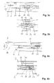
- Die Erfindung ist in den Zeichnungen dargestellt und wird anhand von Ausführungsbeispielen näher erläutert. Es zeigt:
- Fig. 1
- eine erste Ausführungsform der erfindungsgemäße Ausziehführung für eine Schublade in einer perspektivischen Ansicht;
- Fig. 2
- eine Querschnittansicht durch die in
Fig. 1 gezeigte Ausziehführung in ihrer geschlossenen Endstellung; - Fign. 3a, 3b
- eine Seitenansicht (
Fig. 3a ) und eine Detailansicht (Fig. 3b ) der inFig. 1 gezeigten Ausziehführung mit eingezogenem Selbsteinzug; - Fig. 4a, 4b
- eine Seitenansicht (
Fig. 4a ) und eine Detailansicht (Fig. 4b ) der inFig. 1 gezeigten Ausziehführung mit ausgezogenem, gespanntem Selbsteinzug; - Fig. 5
- eine zweite Ausführungsform der erfindungsgemäße Ausziehführung für eine Schublade in einer perspektivischen Ansicht; und
- Fig. 6
- eine Querschnittansicht durch die in
Fig. 5 gezeigte Ausziehführung in ihrer geschlossenen Endstellung. - Die in
Fig. 1 gezeigte Ausziehführung 1 für eine Schublade umfasst eine Korpusschiene 2, eine Schubladenschiene 3 und eine zwischen den beiden laufende Mittelschiene 4. Die Schienen 2, 3, 4 sind über Wälzkörper (nicht gezeigt) relativ zueinander in Längsrichtung verschiebbar geführt. Die Wälzkörper sind innerhalb von Wälzkörperkäfigen von zwei Wälzkörperwagen (nicht gezeigt) drehbar gelagert, von denen der untere Wälzkörperwagen in der Korpusschiene 2 und der obere Wälzkörperwagen in der Schubladenschiene 3 gelagert ist. An der Korpusschiene 2 sind zwei Korpusschenkel 5 zur Befestigung an einem Möbelkorpus vorgesehen. Das gesamte Führungspaket aus den Schienen 2, 3, 4 und ihren Führungen ist inFig. 2 mit 6 bezeichnet. - An der Schubladenschiene 3 ist ein in das Führungspaket 6 integrierter Selbsteinzug 10 befestigt, der die Schubladenschiene 3 kurz vor ihrer geschlossenen Endstellung in diese Endstellung gedämpft einzieht.
- Wie in
Fign. 3 und 4 gezeigt, weist der Selbsteinzug 10 ein längsverschiebbar geführtes, verkippbares Kopplungselement 11, das in einer Führung des Selbsteinzugsgehäuses 12 geführt ist und mit einem an der Korpusschiene 2 vorgesehenen Mitnehmer 13 zusammenwirkt, sowie einen Lineardämpfer 14 zum Dämpfen der Einzugsbewegung auf. - Wie in
Fig. 2 gezeigt, sind der Selbsteinzug 10 und der Mitnehmer 13 in einem vertikalen Zwischenraum 15 angeordnet, der zwischen einem Horizontalsteg 2a der Korpusschiene 2 und einem Horizontalsteg 3a der Schubladenschiene 3 ausgebildet ist. Das Selbsteinzugsgehäuse 12 liegt auf seiner gesamten Länge, also insbesondere auf dem gesamten Verschiebeweg des Kopplungselements 11, mit der oberen Gehäusewand unten am Horizontalsteg 3a der Schubladenschiene 3 an. Auch der Lineardämpfer 14 liegt mit seiner Oberseite unten am Horizontalsteg 3a der Schubladenschiene 3 an. - In
Fign. 3a, 3b ist die Schubladenschiene 3 in ihrer geschlossenen Endstellung mit eingezogenem Selbsteinzug 10 gezeigt, wobei der Mitnehmer 13 in eine Aussparung des hakenförmigen Kopplungselements 11 eingreift. Beim Ausziehen der Schubladenschiene 3 gegenüber der Korpusschiene 2 wird das am Mitnehmer 13 gehaltene Kopplungselement 11 in einer geraden Führungsbahn des Selbsteinzugsgehäuses 12 gegen die Wirkung einer Einzugsfeder (nicht gezeigt) längsverschoben, bis es am Ende der Führungsbahn um eine horizontale Achse 16 in eine Arretierstellung verkippt und dadurch vom Mitnehmer 13 entkoppelt ist. Die Schubladenschiene 3 mit dem nun gespannten Selbsteinzug 10 kann frei bis in ihre geöffnete Endstellung ausgezogen werden. In dieser gespannten verkippten Endstellung liegt das Kopplungselement 11 innen an derjenigen Gehäusewand an, mit der das Selbsteinzugsgehäuse 12 außen am Horizontalsteg 3a anliegt. - Wird die Schubladenschiene 3 geschlossen, so greift kurz vor ihrer geschlossenen Endstellung der Mitnehmer 13 wieder in die Aussparung des Kopplungselements 11 ein und beginnt das Kopplungselement 11 aus seiner Arretierstellung heraus zu drehen. Sobald sich das Kopplungselement 11 wieder in der geraden Führungsbahn befindet, zieht die Einzugsfeder das am Mitnehmer 13 gehaltene Kopplungselement 11 und damit die Schubladenschiene 3 ein (
Fign. 4a, 4b ), wodurch die Schubladenschiene 3 - vom Lineardämpfer 14 gedämpft - in die vollständig eingezogene Stellung gebracht wird. - Da das Selbsteinzugsgehäuse 12 samt Lineardämpfer 14 am Horizontalsteg 3a der Schubladenschiene 3 anliegt und auch das Kopplungselement 11 in seiner gespannten verkippten Endstellung am Selbsteinzugsgehäuse 12 anliegt, werden die durch die Einzugsfeder beim Verkippen des Kopplungselements 11 erzeugten vertikalen Ein- bzw. Auskoppelkräfte unmittelbar auf die Schubladenschiene 3 abgeleitet. Die Schubladenschiene 3 ist einerseits zur Aufnahme hoher vertikaler Schubladenlasten ausgelegt, und anderseits ist die von der Schubladenschiene 3 vertikal aufnehmbare Schubladenlast viel größer als die horizontal aufnehmbaren Kräfte. Die auftretenden Ein- bzw. Auskoppelkräfte des Kopplungselements 11 werden vertikal in Richtung der höheren Lastaufnahme der Schienenführung aufgenommen und dort kaum merklich in das Führungspaket 6 eingeleitet.
- Während die in
Fign. 1 bis 4 gezeigte Ausziehführung 1 aufgrund ihrer Mittelschiene 4 für einen Vollauszug der Schublade ausgebildet, ist die inFign. 5 und 6 gezeigte Ausziehführung 1, die keine Mittelschiene aufweist, lediglich für einen Teilauszug der Schublade ausgebildet. Die Schubladenschiene 3 ist unmittelbar in der Korpusschiene 2 geführt, und der Horizontalsteg 2a der Korpusschiene 2 ist durch einen umgebogenen Lappen der Korpusschiene 2 gebildet, auf dem der Mitnehmer 13 befestigt ist.
Claims (10)
- Ausziehführung (1) für Schubladen oder dgl., mit einer Korpusschiene (2), mit einer Schubladenschiene (3) und mit einem Selbsteinzug (10) zum Einziehen der Schubladenschiene (3) in ihre geschlossene Endstellung,
wobei der Selbsteinzug (10) an der Korpus- oder an der Schubladenschiene (2, 3) befestigt ist und ein längsverschiebbar geführtes, verkippbares Kopplungselement (11) aufweist, das mit einem an der jeweils anderen Schiene (3, 2) vorgesehenen Mitnehmer (13) zusammenwirkt und um eine horizontale Achse (16) in eine Arretierstellung verkippbar ist,
dadurch gekennzeichnet,
dass der Selbsteinzug (10) und der Mitnehmer (13) in einem vertikalen Zwischenraum (15) angeordnet sind, der zwischen einem Horizontalsteg (2a) der Korpusschiene (2) und einem Horizontalsteg (3a) der Schubladenschiene (3) gebildet ist, und dass das Selbsteinzugsgehäuse (12) an dem Horizontalsteg (3a) derjenigen Schiene (3) anliegt, an der der Selbsteinzug (10) befestigt ist. - Ausziehführung nach Anspruch 1, dadurch gekennzeichnet, dass das Selbsteinzugsgehäuse (12) zumindest in den beiden Endpositionen des Kopplungselements (11) am Horizontalsteg (3a) anliegt.
- Ausziehführung nach Anspruch 1 oder 2, dadurch gekennzeichnet, dass das Selbsteinzugsgehäuse (12) auf dem gesamten Verschiebeweg des Kopplungselements (11) am Horizontalsteg (3a) anliegt.
- Ausziehführung nach einem der vorhergehenden Ansprüche, dadurch gekennzeichnet, dass das Selbsteinzugsgehäuse (12) auf seiner gesamten Länge am Horizontalsteg (3a) anliegt.
- Ausziehführung nach einem der vorhergehenden Ansprüche, dadurch gekennzeichnet, dass der Selbsteinzug (10) einen Lineardämpfer (14) aufweist, der am Horizontalsteg (3a) anliegt.
- Ausziehführung nach einem der vorhergehenden Ansprüche, dadurch gekennzeichnet, dass das Kopplungselement (11) in seiner gespannten verkippten Endstellung am Selbsteinzugsgehäuse (12) anliegt.
- Ausziehführung nach einem der vorhergehenden Ansprüche, dadurch gekennzeichnet, dass das Kopplungselement (11) in seiner gespannten verkippten Endstellung innen an derjenigen Gehäusewand des Selbsteinzugsgehäuses (12) anliegt, mit der das Selbsteinzugsgehäuse (12) außen am Horizontalsteg (3a) anliegt.
- Ausziehführung nach einem der vorhergehenden Ansprüche, dadurch gekennzeichnet, dass für einen Vollauszug zwischen Korpus- und Schubladenschiene (2, 3) eine Mittelschiene (4) vorgesehen ist.
- Ausziehführung nach einem der Ansprüche 1 bis 7, dadurch gekennzeichnet, dass für einen Teilauszug die Schubladenschiene (3) unmittelbar in der Korpusschiene (2) geführt ist.
- Ausziehführung nach Anspruch 9, dadurch gekennzeichnet, dass der Horizontalsteg (2a) der Korpusschiene (2) durch einen umgebogenen Lappen der Korpusschiene (2) gebildet ist.
Priority Applications (1)
| Application Number | Priority Date | Filing Date | Title |
|---|---|---|---|
| PL11710725T PL2592966T3 (pl) | 2010-07-14 | 2011-03-18 | Prowadnica wyciągowa dla szuflad |
Applications Claiming Priority (2)
| Application Number | Priority Date | Filing Date | Title |
|---|---|---|---|
| DE202010008079U DE202010008079U1 (de) | 2010-07-14 | 2010-07-14 | Ausziehführung für Schubladen |
| PCT/EP2011/054134 WO2012007189A1 (de) | 2010-07-14 | 2011-03-18 | Ausziehführung für schubladen |
Publications (2)
| Publication Number | Publication Date |
|---|---|
| EP2592966A1 EP2592966A1 (de) | 2013-05-22 |
| EP2592966B1 true EP2592966B1 (de) | 2015-06-24 |
Family
ID=42733633
Family Applications (1)
| Application Number | Title | Priority Date | Filing Date |
|---|---|---|---|
| EP11710725.0A Active EP2592966B1 (de) | 2010-07-14 | 2011-03-18 | Ausziehführung für schubladen |
Country Status (8)
| Country | Link |
|---|---|
| US (1) | US9033433B2 (de) |
| EP (1) | EP2592966B1 (de) |
| CN (1) | CN103002771B (de) |
| DE (1) | DE202010008079U1 (de) |
| DK (1) | DK2592966T3 (de) |
| ES (1) | ES2547906T3 (de) |
| PL (1) | PL2592966T3 (de) |
| WO (1) | WO2012007189A1 (de) |
Families Citing this family (8)
| Publication number | Priority date | Publication date | Assignee | Title |
|---|---|---|---|---|
| CN103919375B (zh) * | 2014-04-25 | 2016-03-02 | 无锡海达尔精密滑轨有限公司 | 三段式隐藏滑轨机构 |
| EP3258196B1 (de) * | 2015-02-13 | 2022-05-25 | LG Electronics Inc. | Kühlschrank |
| DE102016214896A1 (de) * | 2016-08-10 | 2018-02-15 | Schock Metallwerk Gmbh | Auszugführung |
| DE102016120588A1 (de) * | 2016-10-27 | 2018-05-03 | Paul Hettich Gmbh & Co. Kg | Möbel und Verfahren zum Öffnen eines Schubkastens und eines Innenschubkastens |
| AT519982B1 (de) * | 2017-08-17 | 2018-12-15 | Blum Gmbh Julius | Schubladenausziehführung |
| AT17935U1 (de) * | 2017-08-17 | 2023-08-15 | Blum Gmbh Julius | Schubladenausziehführung |
| DE102018118721A1 (de) * | 2018-08-01 | 2020-02-06 | Paul Hettich Gmbh & Co. Kg | Auszug und Verfahren zum Bewegen einer Auszugsführung mit einem Schubelement |
| US11920401B2 (en) | 2021-05-03 | 2024-03-05 | Kohler Co. | Slow close mechanism for sliding applications |
Family Cites Families (29)
| Publication number | Priority date | Publication date | Assignee | Title |
|---|---|---|---|---|
| US5207781A (en) * | 1989-04-03 | 1993-05-04 | Julius Blum Gesellschaft M.B.H. | Closing device for moving a drawer to a fully inserted position within a furniture body |
| DE9114787U1 (de) | 1990-12-14 | 1992-02-20 | Julius Blum Ges.m.b.H., Höchst | Schublade mit einer Schließvorrichtung |
| AT401717B (de) | 1993-06-23 | 1996-11-25 | Blum Gmbh Julius | Schliessvorrichtung für schubladen |
| AT407602B (de) * | 1994-08-31 | 2001-05-25 | Alfit Ag | Einzugsvorrichtung für schubladen |
| DE19835466B4 (de) * | 1998-08-06 | 2004-08-05 | Grass Ges.m.b.H., Metallwarenfabrik, Höchst | Bremsvorrichtung mit Schließfolgeregler für bewegliche Möbelteile |
| MY131087A (en) * | 2002-05-17 | 2007-07-31 | Harn Marketing Sdn Bhd | Closing device for drawers |
| AT413187B (de) | 2003-04-25 | 2005-12-15 | Blum Gmbh Julius | Einzugsvorrichtung für schubladen |
| DE20311795U1 (de) | 2003-07-31 | 2004-11-18 | Alfit Ag | Schubladen-Ausziehführung mit Einzugsautomatik mit integrierter Dämpfung |
| TWI231749B (en) * | 2003-12-24 | 2005-05-01 | Mau-Chin Shen | Restoring/positioning device for slide rail of drawer |
| AT503045B1 (de) | 2004-06-18 | 2008-01-15 | Blum Gmbh Julius | Vorrichtung zum bewegen eines bewegbaren möbelteils |
| CN101384193B (zh) * | 2004-11-05 | 2010-12-08 | 艾库里德国际有限公司 | 自动移动机构及包括该机构的滑动装置 |
| DE202005006724U1 (de) | 2005-02-14 | 2005-07-28 | Grass Gmbh | Schubladenführung |
| MY139488A (en) * | 2005-06-09 | 2009-10-30 | Harn Marketing Sdn Bhd | Closing device |
| US7533946B2 (en) * | 2005-08-25 | 2009-05-19 | Knape & Vogt Manufacturing Company | Closing device for drawers |
| DE202005017635U1 (de) | 2005-11-09 | 2007-03-22 | Grass Gmbh | Lösbare Kupplung zur linearen Kraftübertragung, insbesondere für Schubladenschienen |
| ATE548940T1 (de) * | 2005-11-10 | 2012-03-15 | Grass Gmbh | Vorrichtung zum öffnen und schliessen eines bewegbaren möbelteils und möbelteil |
| JP4806609B2 (ja) * | 2005-11-21 | 2011-11-02 | トックベアリング株式会社 | 引き込みユニット |
| EP1817983A1 (de) * | 2006-02-13 | 2007-08-15 | Grass GmbH | Vorrichtung zur Beeinflussung der Bewegung von relativ zueinander bewegbaren Möbelteilen und Schubladenführung sowie Verfahren zu deren Herstellung |
| TWM302606U (en) * | 2006-06-02 | 2006-12-11 | Gslide Corp | Automatic closing equipment for hidden drawer rail |
| DE202007019190U1 (de) | 2007-02-20 | 2011-02-10 | Karl Simon Gmbh & Co. Kg | Einzugvorrichtung für Schiebelemente |
| AT505053B1 (de) | 2007-04-02 | 2009-02-15 | Fulterer Gmbh | Rollen-differentialausziehführung |
| TWI321995B (en) * | 2007-05-15 | 2010-03-21 | King Slide Works Co Ltd | Drawer slide assembly with an undermount drawer slide |
| US7600828B2 (en) * | 2007-12-20 | 2009-10-13 | King Slide Works Co., Ltd. | Slide assembly having a homing device |
| US8414094B2 (en) * | 2008-02-04 | 2013-04-09 | Accuride International, Inc. | Drawer system slide assemblies and closure mechanisms |
| TWI367083B (en) * | 2008-05-07 | 2012-07-01 | King Slide Works Co Ltd | Retraction mechanism for a drawer |
| DE202008008541U1 (de) | 2008-06-30 | 2009-11-19 | Paul Hettich Gmbh & Co. Kg | Kupplungsvorrichtung zwischen zwei Schienen einer Möbelauszugsführung |
| DE202008016409U1 (de) | 2008-12-13 | 2010-04-22 | Paul Hettich Gmbh & Co. Kg | Selbsteinzugsvorrichtung und Auszugsführung |
| DE202009005433U1 (de) | 2009-04-14 | 2009-07-23 | Häfele GmbH & Co. KG | Schließ- und/oder Einzugsvorrichtung für bewegbare Möbelteile |
| US8240788B2 (en) * | 2010-03-04 | 2012-08-14 | Sun Chain Metal Industry Co., Ltd. | Hidden self-closing drawer slide assembly |
-
2010
- 2010-07-14 DE DE202010008079U patent/DE202010008079U1/de not_active Expired - Lifetime
-
2011
- 2011-03-18 ES ES11710725.0T patent/ES2547906T3/es active Active
- 2011-03-18 DK DK11710725.0T patent/DK2592966T3/en active
- 2011-03-18 EP EP11710725.0A patent/EP2592966B1/de active Active
- 2011-03-18 CN CN201180034604.2A patent/CN103002771B/zh active Active
- 2011-03-18 US US13/810,078 patent/US9033433B2/en active Active
- 2011-03-18 PL PL11710725T patent/PL2592966T3/pl unknown
- 2011-03-18 WO PCT/EP2011/054134 patent/WO2012007189A1/de not_active Ceased
Also Published As
| Publication number | Publication date |
|---|---|
| PL2592966T3 (pl) | 2015-11-30 |
| US9033433B2 (en) | 2015-05-19 |
| EP2592966A1 (de) | 2013-05-22 |
| US20130119843A1 (en) | 2013-05-16 |
| DK2592966T3 (en) | 2015-08-17 |
| WO2012007189A1 (de) | 2012-01-19 |
| DE202010008079U1 (de) | 2010-09-09 |
| ES2547906T3 (es) | 2015-10-09 |
| CN103002771B (zh) | 2016-02-17 |
| CN103002771A (zh) | 2013-03-27 |
Similar Documents
| Publication | Publication Date | Title |
|---|---|---|
| EP1648265B1 (de) | Schubladen-ausziehführung mit einzugsautomatik mit integrierter dämpfung | |
| EP3151701B1 (de) | Schiebe-schwenkmechanik einer ablage eines möbels oder haushaltsgerätes, möbel und haushaltsgerät | |
| WO2012007189A1 (de) | Ausziehführung für schubladen | |
| EP2129260B1 (de) | Rollen-differentialausziehführung | |
| EP2983554B1 (de) | Antriebsvorrichtung für ein bewegbares möbelteil | |
| AT508988B1 (de) | Schubladenausziehführung | |
| EP2916688B1 (de) | Schubladenausziehführung | |
| EP1978842B1 (de) | Antriebsmechanismus für ein an einem möbel bewegbar gelagertes möbelteil | |
| EP3727087B1 (de) | Schubladenausziehführung | |
| DE102017107544A1 (de) | Schiebe- und Hubmechanismus für ein Möbel oder Haushaltsgerät und Möbel oder Haushaltsgerät mit einem derartigen Schiebe- und Hubmechanismus | |
| DE112008001880T5 (de) | Selbstschliessmechanik für Schubkasten-Auszüge | |
| WO2019033136A1 (de) | Schubladenausziehführung | |
| EP2956032B1 (de) | Auszugsführung für ein bewegbares möbelteil | |
| WO2016131775A1 (de) | Schiebe-schwenkmechanik einer ablage eines möbels oder haushaltsgerätes, möbel und haushaltsgerät | |
| EP3654803A1 (de) | Möbel oder haushaltsgerät und verfahren zum öffnen einer tür | |
| DE102014114285A1 (de) | Schiebe-Schwenkmechanik einer Ablage eines Möbels oder Haushaltsgerätes, Möbel und Haushaltsgerät | |
| WO2015185636A1 (de) | Schiebe-schwenkmechanik einer ablage eines möbels oder haushaltsgerätes, möbel und haushaltsgerät | |
| EP1743550B1 (de) | Verschiebungsautomatik für Möbelauszüge, insbesondere Schubladen | |
| WO2005102108A1 (de) | Einzugsautomatik mit dämpfungsvorrichtung für schubladen-ausziehführungen | |
| EP1384420B1 (de) | Gedämpfte Selbsteinzugseinrichtung | |
| AT520805B1 (de) | Ausziehführung | |
| DE102010043271A1 (de) | Geschirrspülmaschine | |
| EP1716782A1 (de) | Auszugsführung | |
| DE102017115952A1 (de) | Schiebe- und Hubmechanismus für ein Möbel oder Haushaltsgerät und Möbel oder Haushaltsgerät mit einem derartigen Schiebe- und Hubmechanismus | |
| WO2015082263A1 (de) | Haushaltskältegerät mit einer führungsvorrichtung für mehrere behälter in einem innenraum des haushaltskältegeräts |
Legal Events
| Date | Code | Title | Description |
|---|---|---|---|
| PUAI | Public reference made under article 153(3) epc to a published international application that has entered the european phase |
Free format text: ORIGINAL CODE: 0009012 |
|
| 17P | Request for examination filed |
Effective date: 20130214 |
|
| AK | Designated contracting states |
Kind code of ref document: A1 Designated state(s): AL AT BE BG CH CY CZ DE DK EE ES FI FR GB GR HR HU IE IS IT LI LT LU LV MC MK MT NL NO PL PT RO RS SE SI SK SM TR |
|
| DAX | Request for extension of the european patent (deleted) | ||
| GRAP | Despatch of communication of intention to grant a patent |
Free format text: ORIGINAL CODE: EPIDOSNIGR1 |
|
| INTG | Intention to grant announced |
Effective date: 20150127 |
|
| GRAS | Grant fee paid |
Free format text: ORIGINAL CODE: EPIDOSNIGR3 |
|
| GRAA | (expected) grant |
Free format text: ORIGINAL CODE: 0009210 |
|
| AK | Designated contracting states |
Kind code of ref document: B1 Designated state(s): AL AT BE BG CH CY CZ DE DK EE ES FI FR GB GR HR HU IE IS IT LI LT LU LV MC MK MT NL NO PL PT RO RS SE SI SK SM TR |
|
| REG | Reference to a national code |
Ref country code: GB Ref legal event code: FG4D Free format text: NOT ENGLISH |
|
| REG | Reference to a national code |
Ref country code: CH Ref legal event code: EP |
|
| REG | Reference to a national code |
Ref country code: AT Ref legal event code: REF Ref document number: 732540 Country of ref document: AT Kind code of ref document: T Effective date: 20150715 |
|
| REG | Reference to a national code |
Ref country code: IE Ref legal event code: FG4D Free format text: LANGUAGE OF EP DOCUMENT: GERMAN |
|
| REG | Reference to a national code |
Ref country code: CH Ref legal event code: NV Representative=s name: RIEDERER HASLER AND PARTNER PATENTANWAELTE AG, LI |
|
| REG | Reference to a national code |
Ref country code: DE Ref legal event code: R096 Ref document number: 502011007141 Country of ref document: DE |
|
| REG | Reference to a national code |
Ref country code: DK Ref legal event code: T3 Effective date: 20150813 |
|
| REG | Reference to a national code |
Ref country code: SE Ref legal event code: TRGR |
|
| REG | Reference to a national code |
Ref country code: ES Ref legal event code: FG2A Ref document number: 2547906 Country of ref document: ES Kind code of ref document: T3 Effective date: 20151009 |
|
| PG25 | Lapsed in a contracting state [announced via postgrant information from national office to epo] |
Ref country code: FI Free format text: LAPSE BECAUSE OF FAILURE TO SUBMIT A TRANSLATION OF THE DESCRIPTION OR TO PAY THE FEE WITHIN THE PRESCRIBED TIME-LIMIT Effective date: 20150624 Ref country code: LT Free format text: LAPSE BECAUSE OF FAILURE TO SUBMIT A TRANSLATION OF THE DESCRIPTION OR TO PAY THE FEE WITHIN THE PRESCRIBED TIME-LIMIT Effective date: 20150624 Ref country code: NO Free format text: LAPSE BECAUSE OF FAILURE TO SUBMIT A TRANSLATION OF THE DESCRIPTION OR TO PAY THE FEE WITHIN THE PRESCRIBED TIME-LIMIT Effective date: 20150924 Ref country code: HR Free format text: LAPSE BECAUSE OF FAILURE TO SUBMIT A TRANSLATION OF THE DESCRIPTION OR TO PAY THE FEE WITHIN THE PRESCRIBED TIME-LIMIT Effective date: 20150624 |
|
| REG | Reference to a national code |
Ref country code: NL Ref legal event code: FP |
|
| REG | Reference to a national code |
Ref country code: LT Ref legal event code: MG4D |
|
| PG25 | Lapsed in a contracting state [announced via postgrant information from national office to epo] |
Ref country code: GR Free format text: LAPSE BECAUSE OF FAILURE TO SUBMIT A TRANSLATION OF THE DESCRIPTION OR TO PAY THE FEE WITHIN THE PRESCRIBED TIME-LIMIT Effective date: 20150925 Ref country code: LV Free format text: LAPSE BECAUSE OF FAILURE TO SUBMIT A TRANSLATION OF THE DESCRIPTION OR TO PAY THE FEE WITHIN THE PRESCRIBED TIME-LIMIT Effective date: 20150624 Ref country code: BG Free format text: LAPSE BECAUSE OF FAILURE TO SUBMIT A TRANSLATION OF THE DESCRIPTION OR TO PAY THE FEE WITHIN THE PRESCRIBED TIME-LIMIT Effective date: 20150924 Ref country code: RS Free format text: LAPSE BECAUSE OF FAILURE TO SUBMIT A TRANSLATION OF THE DESCRIPTION OR TO PAY THE FEE WITHIN THE PRESCRIBED TIME-LIMIT Effective date: 20150624 |
|
| REG | Reference to a national code |
Ref country code: PL Ref legal event code: T3 |
|
| PG25 | Lapsed in a contracting state [announced via postgrant information from national office to epo] |
Ref country code: EE Free format text: LAPSE BECAUSE OF FAILURE TO SUBMIT A TRANSLATION OF THE DESCRIPTION OR TO PAY THE FEE WITHIN THE PRESCRIBED TIME-LIMIT Effective date: 20150624 |
|
| PG25 | Lapsed in a contracting state [announced via postgrant information from national office to epo] |
Ref country code: RO Free format text: LAPSE BECAUSE OF NON-PAYMENT OF DUE FEES Effective date: 20150624 Ref country code: PT Free format text: LAPSE BECAUSE OF FAILURE TO SUBMIT A TRANSLATION OF THE DESCRIPTION OR TO PAY THE FEE WITHIN THE PRESCRIBED TIME-LIMIT Effective date: 20151026 Ref country code: SK Free format text: LAPSE BECAUSE OF FAILURE TO SUBMIT A TRANSLATION OF THE DESCRIPTION OR TO PAY THE FEE WITHIN THE PRESCRIBED TIME-LIMIT Effective date: 20150624 Ref country code: IS Free format text: LAPSE BECAUSE OF FAILURE TO SUBMIT A TRANSLATION OF THE DESCRIPTION OR TO PAY THE FEE WITHIN THE PRESCRIBED TIME-LIMIT Effective date: 20151024 |
|
| REG | Reference to a national code |
Ref country code: FR Ref legal event code: PLFP Year of fee payment: 6 |
|
| REG | Reference to a national code |
Ref country code: DE Ref legal event code: R097 Ref document number: 502011007141 Country of ref document: DE |
|
| PLBE | No opposition filed within time limit |
Free format text: ORIGINAL CODE: 0009261 |
|
| STAA | Information on the status of an ep patent application or granted ep patent |
Free format text: STATUS: NO OPPOSITION FILED WITHIN TIME LIMIT |
|
| 26N | No opposition filed |
Effective date: 20160329 |
|
| PG25 | Lapsed in a contracting state [announced via postgrant information from national office to epo] |
Ref country code: SI Free format text: LAPSE BECAUSE OF FAILURE TO SUBMIT A TRANSLATION OF THE DESCRIPTION OR TO PAY THE FEE WITHIN THE PRESCRIBED TIME-LIMIT Effective date: 20150624 |
|
| PG25 | Lapsed in a contracting state [announced via postgrant information from national office to epo] |
Ref country code: LU Free format text: LAPSE BECAUSE OF FAILURE TO SUBMIT A TRANSLATION OF THE DESCRIPTION OR TO PAY THE FEE WITHIN THE PRESCRIBED TIME-LIMIT Effective date: 20160318 Ref country code: MC Free format text: LAPSE BECAUSE OF FAILURE TO SUBMIT A TRANSLATION OF THE DESCRIPTION OR TO PAY THE FEE WITHIN THE PRESCRIBED TIME-LIMIT Effective date: 20150624 |
|
| REG | Reference to a national code |
Ref country code: DE Ref legal event code: R079 Ref document number: 502011007141 Country of ref document: DE Free format text: PREVIOUS MAIN CLASS: A47B0088040000 Ipc: A47B0088400000 |
|
| REG | Reference to a national code |
Ref country code: IE Ref legal event code: MM4A |
|
| PG25 | Lapsed in a contracting state [announced via postgrant information from national office to epo] |
Ref country code: IE Free format text: LAPSE BECAUSE OF NON-PAYMENT OF DUE FEES Effective date: 20160318 |
|
| REG | Reference to a national code |
Ref country code: FR Ref legal event code: PLFP Year of fee payment: 7 |
|
| PG25 | Lapsed in a contracting state [announced via postgrant information from national office to epo] |
Ref country code: MT Free format text: LAPSE BECAUSE OF FAILURE TO SUBMIT A TRANSLATION OF THE DESCRIPTION OR TO PAY THE FEE WITHIN THE PRESCRIBED TIME-LIMIT Effective date: 20150624 |
|
| REG | Reference to a national code |
Ref country code: FR Ref legal event code: PLFP Year of fee payment: 8 |
|
| PG25 | Lapsed in a contracting state [announced via postgrant information from national office to epo] |
Ref country code: CY Free format text: LAPSE BECAUSE OF FAILURE TO SUBMIT A TRANSLATION OF THE DESCRIPTION OR TO PAY THE FEE WITHIN THE PRESCRIBED TIME-LIMIT Effective date: 20150624 Ref country code: SM Free format text: LAPSE BECAUSE OF FAILURE TO SUBMIT A TRANSLATION OF THE DESCRIPTION OR TO PAY THE FEE WITHIN THE PRESCRIBED TIME-LIMIT Effective date: 20150624 Ref country code: HU Free format text: LAPSE BECAUSE OF FAILURE TO SUBMIT A TRANSLATION OF THE DESCRIPTION OR TO PAY THE FEE WITHIN THE PRESCRIBED TIME-LIMIT; INVALID AB INITIO Effective date: 20110318 |
|
| PG25 | Lapsed in a contracting state [announced via postgrant information from national office to epo] |
Ref country code: MK Free format text: LAPSE BECAUSE OF FAILURE TO SUBMIT A TRANSLATION OF THE DESCRIPTION OR TO PAY THE FEE WITHIN THE PRESCRIBED TIME-LIMIT Effective date: 20150624 |
|
| PG25 | Lapsed in a contracting state [announced via postgrant information from national office to epo] |
Ref country code: AL Free format text: LAPSE BECAUSE OF FAILURE TO SUBMIT A TRANSLATION OF THE DESCRIPTION OR TO PAY THE FEE WITHIN THE PRESCRIBED TIME-LIMIT Effective date: 20150624 |
|
| PGFP | Annual fee paid to national office [announced via postgrant information from national office to epo] |
Ref country code: FR Payment date: 20190326 Year of fee payment: 9 |
|
| PGFP | Annual fee paid to national office [announced via postgrant information from national office to epo] |
Ref country code: IE Payment date: 20190322 Year of fee payment: 17 Ref country code: NL Payment date: 20190321 Year of fee payment: 9 Ref country code: BE Payment date: 20190321 Year of fee payment: 9 |
|
| PG25 | Lapsed in a contracting state [announced via postgrant information from national office to epo] |
Ref country code: CZ Free format text: LAPSE BECAUSE OF NON-PAYMENT OF DUE FEES Effective date: 20200318 |
|
| REG | Reference to a national code |
Ref country code: DK Ref legal event code: EBP Effective date: 20200331 |
|
| REG | Reference to a national code |
Ref country code: NL Ref legal event code: MM Effective date: 20200401 |
|
| REG | Reference to a national code |
Ref country code: BE Ref legal event code: MM Effective date: 20200331 |
|
| PG25 | Lapsed in a contracting state [announced via postgrant information from national office to epo] |
Ref country code: NL Free format text: LAPSE BECAUSE OF NON-PAYMENT OF DUE FEES Effective date: 20200401 |
|
| PG25 | Lapsed in a contracting state [announced via postgrant information from national office to epo] |
Ref country code: FR Free format text: LAPSE BECAUSE OF NON-PAYMENT OF DUE FEES Effective date: 20200331 Ref country code: SE Free format text: LAPSE BECAUSE OF NON-PAYMENT OF DUE FEES Effective date: 20200319 |
|
| PG25 | Lapsed in a contracting state [announced via postgrant information from national office to epo] |
Ref country code: BE Free format text: LAPSE BECAUSE OF NON-PAYMENT OF DUE FEES Effective date: 20200331 |
|
| PG25 | Lapsed in a contracting state [announced via postgrant information from national office to epo] |
Ref country code: DK Free format text: LAPSE BECAUSE OF NON-PAYMENT OF DUE FEES Effective date: 20200331 |
|
| PGFP | Annual fee paid to national office [announced via postgrant information from national office to epo] |
Ref country code: GB Payment date: 20230323 Year of fee payment: 13 |
|
| PGFP | Annual fee paid to national office [announced via postgrant information from national office to epo] |
Ref country code: ES Payment date: 20230414 Year of fee payment: 13 Ref country code: CH Payment date: 20230402 Year of fee payment: 13 |
|
| P01 | Opt-out of the competence of the unified patent court (upc) registered |
Effective date: 20230630 |
|
| REG | Reference to a national code |
Ref country code: CH Ref legal event code: PL |
|
| GBPC | Gb: european patent ceased through non-payment of renewal fee |
Effective date: 20240318 |
|
| PG25 | Lapsed in a contracting state [announced via postgrant information from national office to epo] |
Ref country code: GB Free format text: LAPSE BECAUSE OF NON-PAYMENT OF DUE FEES Effective date: 20240318 |
|
| PG25 | Lapsed in a contracting state [announced via postgrant information from national office to epo] |
Ref country code: GB Free format text: LAPSE BECAUSE OF NON-PAYMENT OF DUE FEES Effective date: 20240318 Ref country code: CH Free format text: LAPSE BECAUSE OF NON-PAYMENT OF DUE FEES Effective date: 20240331 |
|
| REG | Reference to a national code |
Ref country code: ES Ref legal event code: FD2A Effective date: 20250506 |
|
| PG25 | Lapsed in a contracting state [announced via postgrant information from national office to epo] |
Ref country code: ES Free format text: LAPSE BECAUSE OF NON-PAYMENT OF DUE FEES Effective date: 20240319 |
|
| PGFP | Annual fee paid to national office [announced via postgrant information from national office to epo] |
Ref country code: IT Payment date: 20250331 Year of fee payment: 15 |
|
| PGFP | Annual fee paid to national office [announced via postgrant information from national office to epo] |
Ref country code: DE Payment date: 20260327 Year of fee payment: 16 |
|
| PGFP | Annual fee paid to national office [announced via postgrant information from national office to epo] |
Ref country code: AT Payment date: 20260319 Year of fee payment: 16 |
|
| PGFP | Annual fee paid to national office [announced via postgrant information from national office to epo] |
Ref country code: TR Payment date: 20260310 Year of fee payment: 16 |
|
| PGFP | Annual fee paid to national office [announced via postgrant information from national office to epo] |
Ref country code: PL Payment date: 20260224 Year of fee payment: 16 |