EP2592534A2 - Verfahren und Vorrichtung zur Verbesserung der Berührungsempfindlichkeit einer Berührungsbildschirmtafel - Google Patents
Verfahren und Vorrichtung zur Verbesserung der Berührungsempfindlichkeit einer Berührungsbildschirmtafel Download PDFInfo
- Publication number
- EP2592534A2 EP2592534A2 EP12191764.5A EP12191764A EP2592534A2 EP 2592534 A2 EP2592534 A2 EP 2592534A2 EP 12191764 A EP12191764 A EP 12191764A EP 2592534 A2 EP2592534 A2 EP 2592534A2
- Authority
- EP
- European Patent Office
- Prior art keywords
- touch
- receiving channels
- control unit
- sequential
- count
- Prior art date
- Legal status (The legal status is an assumption and is not a legal conclusion. Google has not performed a legal analysis and makes no representation as to the accuracy of the status listed.)
- Withdrawn
Links
Images


Classifications
-
- G—PHYSICS
- G06—COMPUTING OR CALCULATING; COUNTING
- G06F—ELECTRIC DIGITAL DATA PROCESSING
- G06F3/00—Input arrangements for transferring data to be processed into a form capable of being handled by the computer; Output arrangements for transferring data from processing unit to output unit, e.g. interface arrangements
- G06F3/01—Input arrangements or combined input and output arrangements for interaction between user and computer
- G06F3/03—Arrangements for converting the position or the displacement of a member into a coded form
- G06F3/041—Digitisers, e.g. for touch screens or touch pads, characterised by the transducing means
- G06F3/0416—Control or interface arrangements specially adapted for digitisers
- G06F3/0418—Control or interface arrangements specially adapted for digitisers for error correction or compensation, e.g. based on parallax, calibration or alignment
-
- G—PHYSICS
- G06—COMPUTING OR CALCULATING; COUNTING
- G06F—ELECTRIC DIGITAL DATA PROCESSING
- G06F3/00—Input arrangements for transferring data to be processed into a form capable of being handled by the computer; Output arrangements for transferring data from processing unit to output unit, e.g. interface arrangements
- G06F3/01—Input arrangements or combined input and output arrangements for interaction between user and computer
- G06F3/03—Arrangements for converting the position or the displacement of a member into a coded form
- G06F3/041—Digitisers, e.g. for touch screens or touch pads, characterised by the transducing means
- G06F3/0416—Control or interface arrangements specially adapted for digitisers
- G06F3/04166—Details of scanning methods, e.g. sampling time, grouping of sub areas or time sharing with display driving
-
- G—PHYSICS
- G06—COMPUTING OR CALCULATING; COUNTING
- G06F—ELECTRIC DIGITAL DATA PROCESSING
- G06F3/00—Input arrangements for transferring data to be processed into a form capable of being handled by the computer; Output arrangements for transferring data from processing unit to output unit, e.g. interface arrangements
- G06F3/01—Input arrangements or combined input and output arrangements for interaction between user and computer
- G06F3/03—Arrangements for converting the position or the displacement of a member into a coded form
- G06F3/041—Digitisers, e.g. for touch screens or touch pads, characterised by the transducing means
- G06F3/044—Digitisers, e.g. for touch screens or touch pads, characterised by the transducing means by capacitive means
- G06F3/0446—Digitisers, e.g. for touch screens or touch pads, characterised by the transducing means by capacitive means using a grid-like structure of electrodes in at least two directions, e.g. using row and column electrodes
-
- G—PHYSICS
- G06—COMPUTING OR CALCULATING; COUNTING
- G06F—ELECTRIC DIGITAL DATA PROCESSING
- G06F3/00—Input arrangements for transferring data to be processed into a form capable of being handled by the computer; Output arrangements for transferring data from processing unit to output unit, e.g. interface arrangements
- G06F3/01—Input arrangements or combined input and output arrangements for interaction between user and computer
- G06F3/03—Arrangements for converting the position or the displacement of a member into a coded form
- G06F3/041—Digitisers, e.g. for touch screens or touch pads, characterised by the transducing means
- G06F3/044—Digitisers, e.g. for touch screens or touch pads, characterised by the transducing means by capacitive means
- G06F3/0443—Digitisers, e.g. for touch screens or touch pads, characterised by the transducing means by capacitive means using a single layer of sensing electrodes
Definitions
- the present invention relates to a method and apparatus for improving touch sensitivity of a touch screen. More particularly, the present invention relates to a method and apparatus for improving touch sensitivity of a capacitive type touch screen panel.
- touch sensitivity may be reduced in the control unit of the electronic device with the touch screen panel. More particularly, when any touch happens in a free-space state, an unfavorable phenomenon occurs in which touch sensitivity (namely, the level of an electronic signal) is reduced.
- a free-space state denotes a state in which the user does not hold the electronic device. For example, when the user is driving, the user may touch a screen without holding the electronic device because the electronic device is supported by a holder equipped in the vehicle.
- the control unit may fail to recognize a touch event or may recognize it only after a time delay.
- an aspect of the present invention is to provide a method and apparatus for improving touch sensitivity.
- Another aspect of the present invention is to provide a method and apparatus for improving touch sensitivity of a touch screen panel with respect to a touch occurring in a free-space state.
- a method for improving touch sensitivity in an electronic device having a capacitive type touch screen panel includes sequentially driving a plurality of transmitting channels of the touch screen panel using a predetermined scan frequency, determining a sequential touch count by simultaneously scanning a plurality of receiving channels of the touch screen panel wherein the sequential touch count is the number of sequentially touched receiving channels, specifying a scan unit to be used for dividing the plurality of receiving channels into groups on the basis of the sequential touch count and for sequentially scanning the groups of the receiving channels, and determining a touch coordinate by sequentially scanning the plurality of receiving channels using the specified scan unit.
- an apparatus for improving touch sensitivity includes a capacitive type touch screen panel having a plurality of transmitting and receiving channels, and a control unit configured to sequentially drive the plurality of transmitting channels using a predetermined scan frequency, to determine a sequential touch count by simultaneously scanning the plurality of receiving channels wherein the sequential touch count is the number of sequentially touched receiving channels, to specify a scan unit on the basis of the sequential touch count, and to determine a touch coordinate by sequentially scanning the plurality of receiving channels using the specified scan unit.
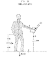
- FIGs. 1A to 1C are views illustrating touch sensitivity characteristics of an electronic device in a hands-on state and a hands-off state according to the related art.
- FIG. 2 is a cross-sectional view illustrating a capacitive type touch screen panel according to an exemplary embodiment of the present invention.
- FIG. 3 is a block diagram illustrating a configuration of a mobile device according to an exemplary embodiment of the present invention.
- FIGs. 4 and 5 are views illustrating a touch sensing unit according to an exemplary embodiment of the present invention.
- FIG. 6 is a flowchart illustrating a method for improving touch sensitivity according to an exemplary embodiment of the present invention.
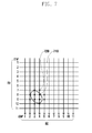
- FIGs. 7 to 9 are views illustrating an arrangement of transmitting channels and receiving channels of a touch screen panel according to an exemplary embodiment of the present invention.
- FIGs. 1A to 1C are views illustrating touch sensitivity characteristics of an electronic device in a hands-on state and a hands-off state according to the related art. Namely, FIGs. 1A to 1C show a reduction effect of touch sensitivity in a capacitive type touch screen panel.
- reference numeral 110 represents a finger of the user
- reference numeral 120 represents a surface of the touch screen panel which is in contact with the finger 110
- reference numeral 130 represents a capacitance accumulated between the user's body and a ground
- Tx represents a transmitting channel for outputting a transmitting signal (Tx signal) to the touch screen panel
- Rx1, Rx2 and Rx3 respectively represent three receiving channels for outputting a received signal (Rx signal) to a control unit.
- a capacitance is formed between the transmitting channel (Tx) and each of the receiving channels (Rx1, Rx2 and Rx3).
- the finger 110 is in contact with the surface 120, a part of the electric flux outputted from the transmitting channel (Tx) is inputted into the finger 110 connected to a ground.
- the capacitance between a transmitting channel (Tx) and a receiving channel (Rx) is varied, and an electric current of a received signal inputted into the control unit is also varied.
- the control unit converts an analog-type received signal inputted from the receiving channel (Rx) into digital data, and determines a touch position based on the digital data.
- the ground connected to the finger 110 may be an electronic device (namely, any ground formed in the electronic device) or the earth ground. More specifically, the earth ground is considered as the ground connected to the finger 110 in case of a free-space state, and any electronic device is considered as the ground connected to the finger 110 when the user holds the electronic device. Charges accumulated at the user's body are quickly discharged when the electronic device is the ground. However, when the earth surface is the ground, charges are accumulated at the user's body for a long time. Therefore, there is an issue that the electric flux may not be inputted into the finger 110 when the earth surface is the ground. Furthermore, there is an issue that the electronic flux is inputted into any adjacent receiving channel not a specific receiving channel actually touched by the user. Unfortunately, these may invite reductions in touch sensitivity such as non-touch, screen trembling, and the like.
- a closed loop is formed between an electronic device and the earth ground through a human body. If the user makes a touch action in this free-space state, charges may not flow directly to the earth's surface but may instead remain in the human body. Moreover, such charges may return to the touch screen panel through the finger. Therefore, the touch sensitivity is reduced and the touch is not recognized. If any touch occurs on a large area, this touch may affect adjacent receiving channels, thereby further reducing touch sensitivity.
- an approach of amplifying a gain of a received signal or increasing a threshold value may be considered.
- this approach may cause a problem in that a noise effect is also amplified.
- Another approach of increasing a thickness between the surface 120 and a channel plane of the touch screen panel may be considered.
- this approach is effective in improving touch sensitivity, it may become an obstacle to obtaining a small size of a smart phone or a tablet Personal Computer (PC).
- an approach of increasing a pitch between the receiving channels may be considered. This approach may, however, have a problem in that touch sensitivity is reduced in case of a touch on a small area. Accordingly, a new approach to improve touch sensitivity while reducing a thickness T without amplifying a gain of a received signal, without artificially increasing a threshold value, and without artificially increasing a pitch is required.
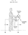
- FIG. 2 is a cross-sectional view illustrating a capacitive type touch screen panel according to an exemplary embodiment of the present invention.
- a touch screen panel 200 may include a cover window 210, an adhesive sheet 220, a sensor sheet 230, and a substrate 240.
- the above-mentioned thickness T may be defined as an interval between the upper surfaces of the cover window 210 and sensor sheet 230 as shown in FIG. 2 .
- the cover window 210 is exposed to the outside of the electronic device. During operation, a surface of the cover window 210 may be in contact with a touch input tool such as a finger.
- the cover window 210 allows light generated in the electronic device to be delivered to the outside.
- This cover window 210 may be formed of Polymethyl Methacrylate (PMMA), Polycarbonate (PC), glass, or any equivalent.
- the adhesive sheet 220 is interposed between the cover window 210 and the sensor sheet 230.
- the adhesive sheet 220 allows the sensor sheet 230 to be firmly disposed on a lower surface of the cover window 210 and allows light generated in the electronic device to be delivered to the cover window 210.
- the adhesive sheet 220 may be formed of Optical Clear Adhesive (OPA), Super View Resin (SVR), or any equivalent.
- the sensor sheet 230 is disposed on the lower surface of the cover window 210 through the adhesive sheet 220.
- the sensor sheet 230 generates an electrical signal according to a touch of the touch input tool with respect to the cover window 210 and delivers the signal to the control unit.
- the sensor sheet 230 has a selected number (M) of transmitting channels (Tx) and a selected number (N) of receiving channels (Rx).
- the M transmitting channels (Tx) and the N receiving channels may be arranged in a matrix form.
- An intersection of the x-th transmitting channel and the y-th receiving channel is defined as a sensing node.
- This sensing node may be represented by x and y coordinates. That is, the sensor sheet 230 includes "M*N" number of sensing nodes.
- the sensor sheet 230 transmits light generated in the electronic device to the adhesive sheet 220.
- the sensor sheet 230 may be formed of any transparent conductive layer, for example, Indium Tin Oxide (ITO).
- ITO Indium Tin Oxide
- the sensor sheet 230 may be deposited on the upper surface of the substrate 240.
- the substrate 240 transmits light generated in the electronic device to the sensor sheet 230.
- the substrate 240 may be formed of glass or any equivalent.
- a noise shield sheet may be formed on a lower surface of the substrate 240.
- the noise shield sheet performs a function to prevent the inflow of a noise created in the electronic device (e.g., at a display unit) into the transmitting channel (Tx) and receiving channel (Rx) of the sensor sheet 230.
- the transmitting channel (Tx) may be formed on the lower surface of the substrate 240 instead of the noise shield sheet. That is, the transmitting channel (Tx) formed on the lower surface of the substrate 240 may perform a function to prevent a noise as well as an inherent function to output a transmitting signal (Tx signal).
- a method and apparatus for improving touch sensitivity in accordance with exemplary embodiments of the present invention may be applied to various types of electronic devices having a capacitive type touch screen panel as discussed above. More particularly, the exemplary touch sensitivity improvement method and apparatus according to this invention may be favorably applied to mobile devices based on handheld portability, which include mobile communication devices, multimedia players and their application equipment, especially including many mobile communication terminals based on various communication protocols, a digital broadcasting player, a Personal Digital Assistant (PDA), a smart phone, a tablet PC, and the like.
- PDA Personal Digital Assistant
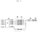
- FIG. 3 is a block diagram illustrating a configuration of a mobile device according to an exemplary embodiment of the present invention.
- the mobile device 300 may include a touch screen panel 310, a key input unit 320, a display unit 330, a memory unit 340, a Radio Frequency (RF) unit 350, an audio processing unit 360, a speaker (SPK), a microphone (MIC), and a control unit 370.
- RF Radio Frequency
- the touch screen panel 310 disposed on the front side of the display unit 330, generates a touch event in response to a user's manipulation on the touch screen panel 310 and delivers it to the control unit 370.
- the control unit 370 recognizes the touch event and may control any of the above elements in response to the touch event.
- the user's manipulation may be a touch, a tap, a double tap, a press, a drag, a drag-and-drop, a sweep, and so forth.
- a touch refers to an action of pressing any point on the screen.
- a tap refers to an action of touching any point on the screen and then releasing (namely, drop) a finger from the touch point without moving the finger.
- a double tap refers to an action of tapping any point on the screen twice.
- a press refers to an action of touching any point on the screen relatively longer than a tap and then releasing a finger from the touch point without moving the finger.
- a drag refers to an action of moving a finger in an arbitrary direction while maintaining a touch on the screen.
- a drag-and-drop refers to an action of dragging and then releasing a finger from the screen.
- a sweep refers to an action of quickly moving and releasing a finger like flipping.
- a drag may be referred to as a scroll, and a sweep may be referred to as a flick.
- the control unit 370 may distinguish a sweep and a drag, depending on a speed of these actions.
- the key input unit 320 includes a plurality of input keys and function keys to receive the user's input actions and to set up various functions.
- the function keys may include navigation keys, side keys, shortcut keys, and any other special keys defined to perform particular functions.
- the key input unit 320 receives the user's key manipulations for controlling the mobile device 300, creates corresponding key input signals, and delivers them to the control unit 370.
- Such key input signals may include power on/off signals, volume regulating signals, screen on/off signals, and the like.
- the control unit 370 controls the above elements.
- the key input unit 320 may be embodied with a mechanical keypad such as a QWERTY keypad, a 3*4 keypad, a 4*3 keypad, or any other key arrangement.
- the key input unit 320 may have only side keys formed on one or more sides of a device body without any key buttons or mechanical keypad.
- the display unit 330 converts image data, received from the control unit 370, into analog signals and displays them. Namely, the display unit 330 may provide various screens such as a lock screen, a home screen, an application executing screen, a menu screen, a message writing screen, an internet browser screen, a soft keypad screen, and the like.
- the lock screen may be provided when the display unit 330 is activated. If a particular touch event for unlock is detected, the control unit 370 may change the lock screen into the home screen or the application executing screen.
- the home screen may contain a plurality of icons corresponding to various applications. When one of the icons is selected by a user, the control unit 370 may execute a corresponding application and change any current screen into the application executing screen.
- the display unit 330 may divide the screen into two or more regions under the control of the control unit 370 and use the divided regions as different screens.
- the display unit 330 may be formed of a Liquid Crystal Display (LCD), Organic Light Emitting Diodes (OLEDs), an Active Matrix OLED (AMOLED), or any other equivalent.
- the display unit 330 may display a left-eye image and a right-eye image and include a 3D implementation unit for providing a user the ability to feel depth with respect to the left-eye and right-eye images.
- 3D implementation technique is classified into a glass type and a glass-free type. Typical examples of the glass type are a color filter type, a polarizing filer type, and a shutter glass type. Typical examples of the glass-free type are a lenticular lens type and a parallax barrier type.
- the memory unit 340 may store various data including an Operating System (OS) of the mobile device and various applications.
- the memory unit 340 may include a program region and a data region.
- the data region of the memory unit 340 may store data created or received while the mobile device 300 is used. And, the data region may store the above-mentioned screens displayed on the display unit 330.
- the soft keypad screen and the menu screen among these screens may have various forms. For instance, the keypad screen may be in 3*4 or QWERTY form.
- the menu screen may include a screen switch key for switching a screen (e.g., a return key for returning to a previous screen) and a control key for controlling an application in use.
- the soft keypad screen and the menu screen may be overlapped with the lock screen, the application executing screen, the home screen, and so forth.
- the data region may temporarily store data copied from messages, photos, web pages, documents, and the like by a user for pasting. Additionally, the data region may store various setup values (e.g., screen brightness, whether a vibration is activated or not in case of touch, whether a screen is rotated automatically, and the like) for operations of the mobile device.
- the program region of the memory unit 340 may store an OS for booting and operating the mobile device, and various applications required for performing various user functions, such as a web browser for access to the Internet, a sound output application, an image viewer application, a video player application, or the like. More particularly, the program region may contain a specific program 341 for improving touch sensitivity.
- This program 341 may have a routine for detecting the number of receiving channels through an entire scan of the receiving channels, a routine for determining, based on the detected number, whether a touch occurs, and a routine for determining touch coordinates through a re-scan for each receiving channel. Also, this program 341 may further have a routine for specifying a scan frequency for the re-scan.
- the RF unit 350 performs a voice call, a video call, or a data communication under the control of the control unit 370.
- the RF unit 350 may include an RF transmitter that up-converts the frequency of an outgoing signal and amplifies the signal, and an RF receiver that amplifies with low-noise an incoming signal and down-converts the frequency of the signal.
- the RF unit 350 may include a mobile communication module (e.g., a 3rd generation mobile communication module or a 4th generation mobile communication module, etc.), a short-distance communication module (e.g., a Wi-Fi module), and a digital broadcast module (e.g., a Digital Multimedia Broadcasting (DMB) module).
- the RF unit 350 may download the program 341 for improving touch sensitivity, from an application store or the like, under the control of the control unit 370.
- the control unit 370 may install the downloaded program 341 in the memory unit 340.
- the audio processing unit 360 sends to the speaker an audio signal received from the control unit 370 and also sends to the control unit 370 an audio signal such as voice received from the microphone. That is, under the control of the control unit 370, the audio processing unit 360 may convert voice/sound data into audible tones through the speaker and also convert audio signals received from the microphone into digital signals.
- the control unit 370 controls operations of the mobile device and signal flows between elements of the mobile device, and processes data. Also, the control unit 370 may control power supply from a battery to the elements. Additionally, the control unit 370 may execute various kinds of applications stored in the program region.
- the control unit 370 as shown in FIGs. 4 and 5 , may include a touch sensing unit for sensing the occurrence of a touch event.
- FIGs. 4 and 5 are views illustrating a touch sensing unit according to an exemplary embodiment of the present invention.
- a touch sensing unit 400 may be disposed in the control unit 370 or between the touch screen panel 310 and the control unit 370.
- an Analog-to-Digital Conversion (ADC) unit 500 may be disposed in the control unit 370 or between the touch sensing unit 400 and the control unit 370. The following descriptions will be given on the assumption that the touch sensing unit 400 and the ADC 500 are disposed between the touch screen panel 310 and the control unit 370.
- the touch sensing unit 400 senses a variation of capacitance in the touch screen panel 310, that is, senses the occurrence of a touch event and outputs the sensed touch event to the ADC 500.
- this touch sensing unit 400 may be composed of "N" number of sensing blocks 410.
- N represents a numeral corresponding to the number of receiving channels (Rx Ch).
- the touch sensing unit 400 senses the occurrence of a touch event for each receiving channel.
- Each of the sensing blocks 410 may have an amplifier 411, a switch 412, a capacitor 413, and a delay unit 414, as shown in FIG. 5 .
- the amplifier 411 amplifies a received signal inputted from the receiving channel of the touch screen panel 310.
- the switch 412 switches a connection between the amplifier 411 and the capacitor 413. This switching is controlled by the control unit 370.
- the capacitor 413 stores a capacitance of a received signal inputted from the receiving channel.
- the delay unit 414 delays the capacitance stored in the capacitor 413 for a predetermined delay time and outputs the stored capacitance to the ADC 500. The delay time is synchronized with the on/off period of the switch 412. If the switch 412 is in the off-state, the capacitance stored in the capacitor 413 is outputted to the ADC 500. On the other hand, if the switch 412 is in the on-state, the capacitance of the received signal inputted from the receiving channel is stored in the capacitor 413.
- the ADC 500 converts the touch event (i.e., an analog signal) inputted from the touch sensing unit 400 into a digital signal and outputs it to the control unit 370.
- the touch sensing unit 400 respectively converts "N" capacitances inputted from "N” sensing blocks 410 into digital data and outputs them to the control unit 370.
- control unit 370 sequentially outputs a transmitting signal to "M" number of transmitting channels Tx.
- the transmitting signal is a square wave.
- the frequency of the square wave is defined as a scan frequency. Namely, the control unit 370 sequentially outputs the square wave from the first to the M-th transmitting channels according to the defined scan frequency.
- the control unit 370 controls all "N" number of switches 412 to be in the on-state when the output square wave is a plus wave form (i.e., above a threshold). On the contrary, the control unit 370 controls all "N" number of switches 412 to be in the off-state when the output square wave is a minus wave form (i.e., below a threshold).
- control unit 370 senses a voltage value with respect to the first to the N-th digital data inputted from the ADC 500 and determines whether each voltage value exceeds a predetermined threshold value. And, if the voltage value exceeds the threshold value, the control unit 370 recognizes that a corresponding receiving channel is touched. That is, the control unit 370 drives the first to the M-th transmitting channels (Tx) one by one. At each time, the control unit 370 simultaneously scans "N" number of receiving channels to obtain the voltage value. After obtaining the voltage value for all sensing nodes of the touch screen panel 310, the control unit 370 compares each voltage value with the threshold value.
- the control unit 370 Based on comparison results, the control unit 370 recognizes the touched sensing node, namely, touch coordinates x and y.
- x and y may be defined as the numeral of the transmitting channel and the numeral of the receiving channel, respectively, or vice versa.
- the control unit 370 may perform a method for improving touch sensitivity as shown in FIG. 6 .
- FIG. 6 is a flowchart illustrating a method for improving touch sensitivity according to an exemplary embodiment of the present invention.
- the control unit 370 sequentially drives the first to the M-th transmitting channels (Tx) with the predetermined scan frequency in step S601. At the same time, the control unit 370 scans "N" number of receiving channels in step S602. When all sensing nodes formed on the touch screen panel 310 are scanned completely, the control unit 370 determines the number of touched receiving channels in step 603. The control unit 370 determines whether a sequential touch count is lower than the threshold value in step S604. The sequential touch count is defined as the number of sequentially touched receiving channels. For instance, if receiving channels #1, #2, #3, and #5 are touched, the sequential touch count becomes three because #5 is excluded.
- the threshold value is used for defining a finger touch. If the sequential touch count exceeds the threshold value, the control unit 370 considers this touch as a non-finger touch (e.g., a palm touch or a cheek touch) and ignores it.
- a non-finger touch e.g., a palm touch or a cheek touch
- step S605 the control unit 370 specifies a scan unit on the basis of the sequential touch count.
- the specified scan unit is defined as a value for classifying "N" number of receiving channels corresponding to the sequential touch count.
- step S606 the control unit 370 may specify a scan frequency on the basis of the sequential touch count.
- step S607 the control unit 370 sequentially drives the first to the M-th transmitting channels (Tx) with the scan frequency newly specified in step S606.
- the control unit 370 sequentially scans "N" number of receiving channels by using the specified scan unit and obtains the voltage values of all sensing nodes formed on the touch screen panel 310 in step S608.
- step S609 the control unit 370 compares each of the obtained voltage values with the threshold value, and, based on the comparison results, the control unit 370 determines the touched sensing node, namely, the touch coordinates x and y. Tthe control unit 370 determines whether the screen is in the off-state in step S610.
- step S610 If the key signal for turning off the screen is inputted from the key input unit 320 in step S610, the control unit 370 stops driving the touch screen panel 310. On the other hand, if the screen is still in the on-state in step S610, the control unit 370 returns to step S601.
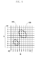
- FIGs. 7 to 9 are views illustrating an arrangement of transmitting channels and receiving channels of a touch screen panel according to an exemplary embodiment of the present invention. The following descriptions will be given on the assumption that the number of transmitting channels and the number of receiving channels are eleven, respectively, and that the threshold value for defining a finger touch is determined in advance as five.
- the control unit 370 determines the sequential touch count by performing the above-discussed steps S601 to S603. If the sequential touch count is two (receiving channels #3 and #4), the control unit 370 recognizes that a finger touch occurs. After that, the control unit 370 specifies a scan unit as 2. The control unit 370 categorizes eleven numbers of receiving channels into two groups, based on the specified scan unit. When the receiving channels are categorized into two groups, any adjacent receiving channels are not included in the same group. That is, a first group has receiving channels #1, #3, #5, #7, #9 and #11, and a second group has receiving channels #2, #4, #6, #8 and #10. Also, the control unit 370 specifies the scan frequency at double.
- the control unit 370 sequentially drives the first to the eleventh transmitting channels, using the double scan frequency. Whenever driving one transmitting channel, the control unit 370 sequentially scans the receiving channels, using the specified scan unit. That is, the control unit 370 scans simultaneously a first category and then scans a second category. Of course, the scan order may be inversed. The control unit 370 scans all sensing nodes in this scan manner and thereby determines touch coordinates.
- reference numeral 710 represents a sensing node touched by a finger
- reference numeral 720 represents a sensing node over which a finger hovers.
- Both a first threshold value for proximity sensing and a second threshold value for touch sensing may be specified.
- the second threshold value is greater than the first threshold value. If the voltage value of the sensing node exceeds the first threshold value and is under the second threshold value, the control unit 370 may recognize that a finger is in the proximity of the sensing node. If the voltage value of the sensing node exceeds the second threshold, the control unit 370 may recognize that the sensing node is touched. For this reason, the control unit 370 may consider any receiving channel close to a finger when determining the sequential touch count.
- the control unit 370 recognizes that a finger touch occurs since four is under the threshold value. Thus, the control unit 370 specifies a scan unit as 4 and categorizes eleven numbers of receiving channels into four groups. As discussed above, any adjacent receiving channels are not included in the same group. That is, a first group has receiving channels #1, #5 and #9, a second group has receiving channels #2, #6 and #10, a third group has receiving channels #3, #7 and #11, and a fourth group has receiving channels #4 and #8. Also, the control unit 370 specifies the scan frequency at quadruple.
- the control unit 370 sequentially drives the first to the eleventh transmitting channels, using the quadruple scan frequency. Whenever driving one transmitting channel, the control unit 370 sequentially scans the receiving channels from a first category to a fourth category, using the specified scan unit. The control unit 370 scans all sensing nodes in this scan manner and thereby determines touch coordinates.
- the control unit 370 defines a relatively greater touch region as a region for specifying a scan unit and a scan frequency. As shown, the control unit 370 selects a second touch region 920 greater than a first touch region 910 and determines a sequential touch count in the selected touch region 920. The subsequent process is substantially the same as previously discussed with reference to FIG. 8 .
- the above-discussed mobile device may essentially or selectively include any other elements.
- the mobile device may further include a short range communication module, a digital camera module, a wired or wireless data transmission interface, an Internet access module, a digital broadcast receiving module, and so forth.
- a digital convergence tendency such elements may be varied, modified and improved in various ways, and any other elements equivalent to the above elements may be additionally or alternatively equipped in the portable device.
- some of the above-mentioned elements in the mobile device may be omitted or replaced with another.
- These computer program instructions may also be stored in a computer usable or computer-readable memory that can direct a computer or other programmable data processing apparatus to function in a particular manner, such that the instructions stored in the computer usable or computer-readable memory produce an article of manufacture including instruction means that implement the function specified in the flowchart block or blocks.
- the computer program instructions may also be loaded onto a computer or other programmable data processing apparatus to cause a series of operational steps to be performed on the computer or other programmable apparatus to produce a computer implemented process such that the instructions that are executed on the computer or other programmable apparatus provide steps for implementing the functions specified in the flowchart block or blocks.
- each block of the flowchart illustrations may represent a module, segment, or portion of code, which comprises one or more executable instructions for implementing the specified logical function(s). It should also be noted that, in some alternative implementations, the functions noted in the blocks may occur out of order. For example, two blocks shown in succession may in fact be executed substantially concurrently or the blocks may sometimes be executed in the reverse order, depending upon the functionality involved.
Landscapes
- Engineering & Computer Science (AREA)
- General Engineering & Computer Science (AREA)
- Theoretical Computer Science (AREA)
- Human Computer Interaction (AREA)
- Physics & Mathematics (AREA)
- General Physics & Mathematics (AREA)
- Position Input By Displaying (AREA)
Applications Claiming Priority (1)
| Application Number | Priority Date | Filing Date | Title |
|---|---|---|---|
| KR1020110116399A KR101895883B1 (ko) | 2011-11-09 | 2011-11-09 | 터치스크린패널의 터치 감도 개선 방법 및 장치 |
Publications (2)
| Publication Number | Publication Date |
|---|---|
| EP2592534A2 true EP2592534A2 (de) | 2013-05-15 |
| EP2592534A3 EP2592534A3 (de) | 2015-09-02 |
Family
ID=47137622
Family Applications (1)
| Application Number | Title | Priority Date | Filing Date |
|---|---|---|---|
| EP12191764.5A Withdrawn EP2592534A3 (de) | 2011-11-09 | 2012-11-08 | Verfahren und Vorrichtung zur Verbesserung der Berührungsempfindlichkeit einer Berührungsbildschirmtafel |
Country Status (4)
| Country | Link |
|---|---|
| US (1) | US9348471B2 (de) |
| EP (1) | EP2592534A3 (de) |
| KR (1) | KR101895883B1 (de) |
| CN (1) | CN103105983B (de) |
Families Citing this family (10)
| Publication number | Priority date | Publication date | Assignee | Title |
|---|---|---|---|---|
| US11826636B2 (en) * | 2013-07-12 | 2023-11-28 | Chris Argiro | Depth sensing module and mobile device including the same |
| US9778784B2 (en) * | 2013-03-14 | 2017-10-03 | Rich IP Technology Inc. | Touch display driving circuit capable of responding to CPU commands |
| US20150193259A1 (en) * | 2014-01-03 | 2015-07-09 | Advanced Micro Devices, Inc. | Boosting the operating point of a processing device for new user activities |
| JP2016115011A (ja) * | 2014-12-11 | 2016-06-23 | トヨタ自動車株式会社 | タッチ操作検出装置 |
| CN104461151B (zh) * | 2014-12-22 | 2018-01-26 | 西安中颖电子有限公司 | 低压高信噪比的触摸屏检测方法 |
| WO2018116136A1 (en) * | 2016-12-20 | 2018-06-28 | 3M Innovative Properties Company | Electrode pattern for capacitive touch sensor |
| CN109039321A (zh) * | 2018-10-15 | 2018-12-18 | 湖南品腾电子科技有限公司 | 一种触摸按键装置及灵敏度自动调整方法 |
| KR102811860B1 (ko) * | 2020-12-29 | 2025-05-22 | 엘지디스플레이 주식회사 | 터치장치, 이를 포함하는 터치표시장치 및 그 구동방법 |
| CN112799533B (zh) * | 2021-01-15 | 2023-02-21 | 青岛海信商用显示股份有限公司 | 触控点确定方法和触控设备 |
| CN115933952B (zh) * | 2021-08-28 | 2023-11-24 | 荣耀终端有限公司 | 一种触控采样率调节方法及相关装置 |
Family Cites Families (21)
| Publication number | Priority date | Publication date | Assignee | Title |
|---|---|---|---|---|
| US3732369A (en) * | 1971-04-05 | 1973-05-08 | Welland Investment Trust | Coordinate digitizer system |
| US4698461A (en) * | 1986-08-26 | 1987-10-06 | Tektronix, Inc. | Touch panel with automatic frequency control |
| US8076949B1 (en) * | 2007-03-30 | 2011-12-13 | Cypress Semiconductor Corporation | Enhanced proximity sensing |
| KR20090027066A (ko) * | 2007-09-11 | 2009-03-16 | 리디스 테크놀로지 인코포레이티드 | 터치 패드 구동 장치 및 구동 방법 |
| US9075483B2 (en) | 2007-12-21 | 2015-07-07 | Apple Inc. | Negative pixel compensation |
| EP2291729B1 (de) * | 2008-04-30 | 2013-06-05 | N-Trig Ltd. | Mehrfachberührungsdetektion |
| TW201011605A (en) | 2008-09-01 | 2010-03-16 | Turbotouch Technology Inc E | Method capable of preventing mistakenly triggering a touch panel |
| US8810542B2 (en) | 2008-09-10 | 2014-08-19 | Apple Inc. | Correction of parasitic capacitance effect in touch sensor panels |
| TWI472993B (zh) | 2009-02-11 | 2015-02-11 | Elan Microelectronics Corp | Touch circuit and scanning method of capacitive touch sensor |
| JP5193942B2 (ja) | 2009-05-14 | 2013-05-08 | 京セラディスプレイ株式会社 | 静電容量型タッチパネル装置 |
| US8482544B2 (en) | 2009-07-10 | 2013-07-09 | Apple Inc. | Negative pixel compensation |
| US9632622B2 (en) | 2009-07-16 | 2017-04-25 | Apple Inc. | Ground detection for touch sensitive device |
| CN101980123B (zh) * | 2009-08-25 | 2012-07-04 | 友达光电股份有限公司 | 具高触碰灵敏度的触碰面板装置与其触碰定位方法 |
| US8749512B2 (en) | 2009-09-30 | 2014-06-10 | Apple Inc. | Negative pixel compensation |
| US20110100727A1 (en) | 2009-10-30 | 2011-05-05 | Shin John Choi | Touch Sensitive Device with Dielectric Layer |
| US9244569B2 (en) * | 2010-03-31 | 2016-01-26 | Stmicroelectronics Asia Pacific Pte Ltd | Capacitive sensing analog front end |
| TWI605359B (zh) * | 2010-04-02 | 2017-11-11 | 晨星半導體股份有限公司 | 觸控板之手勢辨識方法與手勢辨識裝置 |
| US8890834B2 (en) * | 2010-04-13 | 2014-11-18 | Himax Technologies Limited | Scanning method of a touch panel |
| CN102012765A (zh) * | 2011-01-04 | 2011-04-13 | 苏州瀚瑞微电子有限公司 | 一种触摸屏的扫描方法 |
| TWI571788B (zh) * | 2011-03-21 | 2017-02-21 | 宸鴻光電科技股份有限公司 | 觸控感測裝置及其掃描方法 |
| US9372580B2 (en) | 2011-12-21 | 2016-06-21 | Atmel Corporation | Enhanced touch detection methods |
-
2011
- 2011-11-09 KR KR1020110116399A patent/KR101895883B1/ko not_active Expired - Fee Related
-
2012
- 2012-11-02 US US13/667,522 patent/US9348471B2/en not_active Expired - Fee Related
- 2012-11-08 EP EP12191764.5A patent/EP2592534A3/de not_active Withdrawn
- 2012-11-09 CN CN201210449086.7A patent/CN103105983B/zh not_active Expired - Fee Related
Non-Patent Citations (1)
| Title |
|---|
| None |
Also Published As
| Publication number | Publication date |
|---|---|
| KR20130051189A (ko) | 2013-05-20 |
| US9348471B2 (en) | 2016-05-24 |
| US20130113753A1 (en) | 2013-05-09 |
| CN103105983B (zh) | 2017-07-07 |
| CN103105983A (zh) | 2013-05-15 |
| KR101895883B1 (ko) | 2018-09-10 |
| EP2592534A3 (de) | 2015-09-02 |
Similar Documents
| Publication | Publication Date | Title |
|---|---|---|
| US9348471B2 (en) | Method and apparatus for improving touch sensitivity of touch screen panel | |
| US10082873B2 (en) | Method and apparatus for inputting contents based on virtual keyboard, and touch device | |
| KR101837815B1 (ko) | 측벽 디스플레이를 갖는 전자 디바이스 | |
| US20110193805A1 (en) | Screen control method and apparatus for mobile terminal having multiple touch screens | |
| WO2011037222A1 (ja) | 携帯端末装置、携帯端末装置の制御方法、およびプログラム | |
| JP2018505497A (ja) | マルチタッチジェスチャのためのシステムおよび方法 | |
| US10007375B2 (en) | Portable apparatus and method for controlling cursor position on a display of a portable apparatus | |
| EP2372539A2 (de) | Vorrichtung und Verfahren zur Bearbeitung eines Liste in einem tragbaren Endgerät | |
| US20150169216A1 (en) | Method of controlling screen of portable electronic device | |
| JP2012505567A (ja) | 開いているウインドウのライブプレビュー | |
| CA2680666A1 (en) | An electronic device having a state aware touchscreen | |
| KR20150092672A (ko) | 복수 개의 윈도우를 디스플레이하는 방법 및 장치 | |
| WO2014077296A1 (ja) | 携帯端末およびロック状態制御方法 | |
| EP4160370B1 (de) | Symbolanordnungsverfahren, elektronische vorrichtung und speichermedium | |
| CN108984092B (zh) | 设备控制方法、装置、存储介质及电子设备 | |
| WO2013176242A1 (ja) | タッチ検出機能を有する電子機器、プログラムおよびタッチ検出機能を有する電子機器の制御方法 | |
| US9417724B2 (en) | Electronic apparatus | |
| US9042939B2 (en) | Portable electronic device and control method | |
| CN106293184B (zh) | 可侧边触控的终端及其触控方法 | |
| JP5306430B2 (ja) | 携帯端末装置 | |
| JP5969320B2 (ja) | 携帯端末装置 | |
| US12079393B2 (en) | Tactile feedback | |
| KR102033710B1 (ko) | 터치스크린 그래픽 유저 인터페이스 제어 방법 | |
| JP2016181291A (ja) | 装置、制御方法、ならびに制御プログラム | |
| JP2011227671A (ja) | 入力装置及び電子機器 |
Legal Events
| Date | Code | Title | Description |
|---|---|---|---|
| PUAI | Public reference made under article 153(3) epc to a published international application that has entered the european phase |
Free format text: ORIGINAL CODE: 0009012 |
|
| AK | Designated contracting states |
Kind code of ref document: A2 Designated state(s): AL AT BE BG CH CY CZ DE DK EE ES FI FR GB GR HR HU IE IS IT LI LT LU LV MC MK MT NL NO PL PT RO RS SE SI SK SM TR |
|
| AX | Request for extension of the european patent |
Extension state: BA ME |
|
| PUAL | Search report despatched |
Free format text: ORIGINAL CODE: 0009013 |
|
| AK | Designated contracting states |
Kind code of ref document: A3 Designated state(s): AL AT BE BG CH CY CZ DE DK EE ES FI FR GB GR HR HU IE IS IT LI LT LU LV MC MK MT NL NO PL PT RO RS SE SI SK SM TR |
|
| AX | Request for extension of the european patent |
Extension state: BA ME |
|
| RIC1 | Information provided on ipc code assigned before grant |
Ipc: G06F 3/044 20060101ALI20150724BHEP Ipc: G06F 3/041 20060101AFI20150724BHEP |
|
| 17P | Request for examination filed |
Effective date: 20160302 |
|
| STAA | Information on the status of an ep patent application or granted ep patent |
Free format text: STATUS: THE APPLICATION HAS BEEN WITHDRAWN |
|
| 18W | Application withdrawn |
Effective date: 20180919 |