EP2592208B1 - Gate - Google Patents
Gate Download PDFInfo
- Publication number
- EP2592208B1 EP2592208B1 EP12006514.9A EP12006514A EP2592208B1 EP 2592208 B1 EP2592208 B1 EP 2592208B1 EP 12006514 A EP12006514 A EP 12006514A EP 2592208 B1 EP2592208 B1 EP 2592208B1
- Authority
- EP
- European Patent Office
- Prior art keywords
- gate
- leg
- gate leaf
- bridging element
- bridging
- Prior art date
- Legal status (The legal status is an assumption and is not a legal conclusion. Google has not performed a legal analysis and makes no representation as to the accuracy of the status listed.)
- Active
Links
- 238000007789 sealing Methods 0.000 claims description 24
- 238000010276 construction Methods 0.000 claims description 14
- 229910052782 aluminium Inorganic materials 0.000 claims description 2
- XAGFODPZIPBFFR-UHFFFAOYSA-N aluminium Chemical compound [Al] XAGFODPZIPBFFR-UHFFFAOYSA-N 0.000 claims description 2
- 239000004411 aluminium Substances 0.000 claims 1
- 230000007704 transition Effects 0.000 description 10
- 229910000831 Steel Inorganic materials 0.000 description 3
- 230000000694 effects Effects 0.000 description 3
- 229910052751 metal Inorganic materials 0.000 description 3
- 239000002184 metal Substances 0.000 description 3
- 239000010959 steel Substances 0.000 description 3
- 239000006260 foam Substances 0.000 description 2
- 238000010079 rubber tapping Methods 0.000 description 2
- 239000002023 wood Substances 0.000 description 2
- 238000005253 cladding Methods 0.000 description 1
- 230000007547 defect Effects 0.000 description 1
- 230000001419 dependent effect Effects 0.000 description 1
- 238000006073 displacement reaction Methods 0.000 description 1
- 238000009434 installation Methods 0.000 description 1
- 238000009413 insulation Methods 0.000 description 1
- 230000010354 integration Effects 0.000 description 1
- 239000000463 material Substances 0.000 description 1
- 230000000149 penetrating effect Effects 0.000 description 1
- 239000007787 solid Substances 0.000 description 1
Images


Classifications
-
- E—FIXED CONSTRUCTIONS
- E06—DOORS, WINDOWS, SHUTTERS, OR ROLLER BLINDS IN GENERAL; LADDERS
- E06B—FIXED OR MOVABLE CLOSURES FOR OPENINGS IN BUILDINGS, VEHICLES, FENCES OR LIKE ENCLOSURES IN GENERAL, e.g. DOORS, WINDOWS, BLINDS, GATES
- E06B3/00—Window sashes, door leaves, or like elements for closing wall or like openings; Layout of fixed or moving closures, e.g. windows in wall or like openings; Features of rigidly-mounted outer frames relating to the mounting of wing frames
- E06B3/32—Arrangements of wings characterised by the manner of movement; Arrangements of movable wings in openings; Features of wings or frames relating solely to the manner of movement of the wing
- E06B3/48—Wings connected at their edges, e.g. foldable wings
- E06B3/485—Sectional doors
Definitions
- the invention relates to a gate according to the preamble of patent claim 1.
- Gates of this type are, for example, realized in the form of so-called. Sectional doors.
- the door leaf consists of a plurality of relative to the path of movement between the closed position and the open position extending pivot axes pivotable door leaf elements.
- guide rails which are approximately parallel to the lateral edges of the door leaf in the Having closed position extending, approximately perpendicularly extending portion, a parallel to the lateral edges of the door leaf in the open position extending horizontal guide rail portion and the two rectilinear horizontally or vertically extending guide rail sections interconnecting arcuate guide rail section.
- the transition arrangement of corresponding gates serves on the one hand to seal the transition between the door leaf and the soffit in the closed position and on the other hand for fixing the vertical guide rails.
- conventional sectional doors have transitional arrangements in the form of so-called lateral frame beams, which are regularly designed as angle profiles made of sheet steel, usually a guide rail having the guide rail legs, an approximately parallel thereto and possibly cooperating with a sealing strip for sealing the transition between the door leaf and soffit serving sealing leg and a connecting leg connecting the guide rail leg with the sealing strip and preferably forming the outer surface of the transition device, the sealing leg extending from the connecting leg towards the door leaf in the closed position so that the connecting leg, guide rail leg and sealing leg have an overall U-profile shortened lateral leg, the sealing leg form.
- the attachment of the thus executed side frame spar with respect to the soffit can be done either via the guide rail legs or over the connecting leg.
- the outer boundary surface of the door leaf in the closed position with respect to the remote from the door leaf to be closed space outer surface of the wall having the opening arranged offset, so that enough space for the seal arrangement between the outer surface of the wall having a plane and the outer Boundary surface of the door leaf in the closed position having level remains without the lateral Zargenholm must project beyond the soffit out into the outer space.
- Gates according to the preamble of claim 1 are in the DE 10 2005 023 348 B3 specified. Furthermore, in the US 2009/0223131 A1 Sectional door leaves described with a frame construction in which, for example, made of wood panels are attached to a metal frame.
- the object of the invention is to provide gates which make it possible to provide a desired appearance of a facade without the need for separate facade elements for the area of the door leaf, with which in the closed position a tight transition between the transition arrangement and the door leaf can be guaranteed.
- the door leaf at least one attachable to the outer boundary surface and fixable with respect to the outer boundary surface bridging element for bridging a distance to an outer wall surface of the opening wall and / or or the outer surface of the transition arrangement is assigned in a direction perpendicular to it, ie to the outer surface or to the outer boundary surface extending direction.
- the invention is based on the incredibly simple knowledge that it is sufficient to obtain the desired design effect to provide easy to produce and attachable to the door leaf bridging elements with which the offset between Outer wall surface and outer boundary surface of the door leaf can be bridged because such bridging elements are completely covered by the facade elements to be fastened thereto, so that they can be easily manufactured and attached to the outer boundary surface of the door leaf.
- the transition arrangement has a fixed relative to the soffit lateral Zargenholm with at least one attached and serving to guide the Torblattterrorism between the open position and the closed position guide rail and a sealing arrangement for sealing the transition between the outer boundary surface of the
- the one fixed relative to the soffit and the guide rail having guide rail legs, an approximately parallel thereto sealing leg and the guide rail leg with the Sealing connecting leg and preferably the outer surface forming connecting leg, wherein the sealing leg, starting from the Connecting leg extending in the direction of the door leaf in the closed position and the Zargenholm can be set in total either in the region of the guide rail leg or in the region of the connecting leg with respect to the soffit.
- the Zargenholm is fixed in the region of the guide rail leg on a soffit surface which is perpendicular to the door leaf in the closed position or at sectional doors perpendicular to the pivot axes.
- a soffit surface which is perpendicular to the door leaf in the closed position or at sectional doors perpendicular to the pivot axes.
- the sealing leg of Zargenholme inventive gates on its side facing away from the connecting leg edge for receiving a also after attachment of the bridging element and possibly the facade elements it in the closed position can be applied to the outer boundary surface of the door leaf sealing strip designed groove.
- the Zargenholm can be achieved in total in the form of a cold-formed steel sheet, wherein the groove can be produced by appropriate folding of Zargenholms.
- the invention can be used with particular advantage in so-called sectional doors, in which the door leaf have a plurality of relative to its trajectory between the open position and the closed position extending pivot axes against each other pivotable Torblattemian.
- the door leaf elements can be realized, for example, in the form of so-called sandwich elements, in which a foam core is accommodated between two metal shells.
- At least one door leaf element a frame construction with at least two parallel to the pivot axes extending cross members and at least two, preferably three or more perpendicular thereto extending connecting struts, preferably at least one bridging element extends approximately parallel to the connecting struts and on the Torblattau batseite releasably secured to at least one transverse strut and / or at least one connecting strut.
- bridging elements can be structurally particularly simple if at least one fixed relative to the door leaf and preferably approximately parallel to a transverse strut extending guide element is provided along which the bridging element displaceable and. With respect to which it is preferably fixable.
- the guide element can be embodied, for example, in the form of a U-profile with a connecting leg and two outer limbs extending from opposite edges of the connecting leg in a direction extending approximately perpendicular thereto, wherein the edges of the outer limb facing away from the connecting leg are bent towards one another, so that an almost closed space between connecting legs, outer legs and the mutually curved edges is formed, which is open only along a extending between the edges of the outer leg slot.
- the bridging elements can be fastened thereto by means of a bolt penetrating the bridging element and a space accommodated in the space formed by the guide element, the fitting, on tightening the fastening screw, abutting the outer limbs on the one hand and the edges of the outer limbs bent towards each other on the other hand to achieve such a frictional determination of the bridging elements with respect to the guide elements.
- the guide element itself can also be screwed onto the door leaf, esp. The cross struts.
- the space between the individual struts of the frame construction can be filled by suitable fillings, such as glazings, but also other design elements. These fillings are possibly unfavorable in connection with the other facade design. Therefore, the fillings can be covered by using inventive structures by attached to the bridging elements facade elements.
- the bridging elements and / or guide elements can be detachably fixed to the frame construction.
- at least one transverse strut and / or at least one connecting strut can have a threaded bore for receiving a fastening screw or a corresponding screw bolt passing through the bridging element and / or guide element.
- the bridging element and / or guide element can be easily placed on the outer boundary surface of the frame and fastened thereto by means of the fastening screw.
- bridging elements and / or guide elements In connection with the filling of frame constructions often investment strips are used, which are attached to the struts of the frame structure or designed in one piece with it and serve to create possibly plate-shaped fillings. These investment strips can extend over the entire height and / or the entire width of the struts.
- at least one bridging element and / or guide element can be releasably secured to at least one contact strip.
- the contact strip can be penetrated by a recess for receiving a fastening screw recess.
- the attachment of the bridging elements and / or guide elements can also be carried out in these constructions, that the fastening screw or the fastening bolt passes through the recess in the contact strip and is determined by using a fastening nut.
- the construction according to the invention allows a pleasing facade design using simple components.
- at least one bridging element in the form of a hollow profile, esp. Aluminum hollow profile, with two mutually parallel and each penetrated by a serving for receiving a fastening screw recess wall be realized, wherein the recesses lie in the walls on a common perpendicular to the walls extending straight lines in that the fastening screw passes through the bridging element in a direction perpendicular to the outer boundary surface of the door leaf in the closed position.
- the recess in the wall facing away from the door to be closed with the door panel may have a larger diameter than the recess in the wall to be closed with the door leaf to be closed.
- the fastening screw through the first opening can be easily performed and a tool, such as a screwdriver, be used to screw this screw, while the opening in the wall facing the door to be closed with the door closes with a smaller diameter in that a screw head or bolt head, if appropriate with the interposition of a suitable washer, comes into contact with the wall penetrated by the opening.
- the length of the bridging element is less than the height of the Torblattelements in a direction parallel to the connecting struts direction.
- gates according to the invention preferably have at least one facade element which is preferably detachably fastened to the bridging element.
- Sectional gate shown comprises a door leaf with a plurality of executed in a frame construction Torblattmaschinen 10 and a generally designated 50 transition arrangement in the form of a side frame spar.
- the lateral Zargenholm comprises a guide rail leg 52 to which a guide rail 60 is fixed, a sealing leg 54 with a serving for receiving a sealing strip 62 groove 56 and the guide rail leg 52 with the parallel thereto sealing leg 54 connecting connecting leg 58 whose outer boundary surface 14 with the outer wall surface 80 of the wall to be closed having the opening to be closed.
- facade elements 82 are placed on the outer wall 80 facade elements 82 are placed.
- 10 facade elements 12 are placed on the outer boundary surface 14 of the door leaf element.
- the facade elements 12 have a substantially greater thickness than the facade elements 82, so that the distance between the outer boundary surface 14 and the outer wall 80 is bridged in a direction perpendicular thereto such that the outer boundary surface 14 of the facade elements 12 with the outer boundary surface 14 of the facade elements 82 is aligned.
- gates bridging elements 30 are placed on the outer boundary surface 14 of a frame structure having Torblattelements 10.
- Each of the bridging elements 30 is releasably secured to cross members 16 of the frame structure.
- the bridging elements 30 bores 32, guided by the connecting screws or bolts and can be introduced to secure the bridging elements 30 to the cross struts 16 of the Torblattelements 10 in threaded holes, which are provided in the cross struts 16 or by self-tapping screws in the cross struts sixteenth get cut.
- the transverse struts 16 of the frame construction are connected to one another via connecting struts 18, which run perpendicular to the transverse struts 16. Between the connecting struts 18 and the transverse struts 16 a space is left, which can be filled by a filling, such as a transparent pane.
- facade elements of the same thickness as the facade elements 82 can be placed. It is important in the design of the facade to ensure that the pitch of the facade elements 82 in the vertical direction with the height of the door leaf elements 10 is compatible, so that a continuous gap between successive facade elements 82 is continued in the area of the door leaf elements 10. The joint then runs in the horizontal direction between the hingedly interconnected Torblattmaschinen 10th
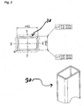
- the bridging elements 30 are executed in the embodiment of the invention shown in the drawing as hollow sections with a substantially rectangular cross-section.
- Opposite walls, one of which is applied to the outer boundary surface 14 of the Torblattelements 10 and the other facing away from the door to be closed with the door space, are penetrated by holes 32 which lie on a perpendicular to the walls straight lines, so that the holes 32 can be penetrated by screws.
- the bore 32 in the wall facing away from the space to be fired is designed with a larger diameter than the bore 32 in the wall to be applied to the outer boundary surface 14 of the door leaf element 10.
- FIG. 3 illustrated embodiment of the invention differs essentially by the in the Fig. 1 and 2 illustrated embodiment that the bridging elements 30 are slidably secured to the transverse struts 16 of the door leaf element 10.
- 10 guide elements 100 are attached to the cross struts 16 of the door leaf element.
- the guide elements 100 are designed in the form of U-profiles with a voltage applied to the transverse struts 16 connecting leg and two extending from opposite edges of the connecting leg in perpendicular planes extending outer legs.
- the edges of the outer limb facing away from the connecting leg are bent towards one another, so that the U-profile forms a closed chamber with the exception of a slot formed between the edges of the outer limb facing away from the connecting leg, as is particularly clear in FIG Fig. 3b ) is recognizable.
- Self-tapping screws 110 are provided for fastening the guide elements 100 to the cross struts 16, which pass through holes in the connecting leg, wherein the holes are dimensioned so that a screw head rests against the material region adjacent to the holes.
- bridging elements 30 For fixing the bridging elements 30 to the guide elements 100, threaded bolts 120 are provided, which pass through holes in the bridging elements 30 and are screwed into shaped pieces 122. The fittings 122 are received in the channel formed in the guide member. With the screws 120 loosened, the bridging elements 30 can be guided by those in the channels in the guide elements 100 recorded fittings 21 are moved along the guide elements 100. The bridging elements 30 can be locked by tightening the bolts 120 at the desired location. When tightening the bolts 120, the shaped pieces 122 are applied to the mutually bent edges of the outer legs of the guide elements 100, resulting in a non-positive fixing of the bridging elements 30 with respect to the guide elements 100.
- gates according to the invention can be designed with so-called sandwich panels, in which a foam core is accommodated between two metal shells.
- the invention can also be used profitably in so-called tilt gates with integral door leaves.
Landscapes
- Engineering & Computer Science (AREA)
- Civil Engineering (AREA)
- Structural Engineering (AREA)
- Wing Frames And Configurations (AREA)
- Building Environments (AREA)
Description
Die Erfindung betrifft ein Tor nach dem Oberbegriff des Patentanspruchs 1.The invention relates to a gate according to the preamble of
Tore dieser Art werden bspw. in Form von sog. Sektionaltoren verwirklicht. Bei diesen Sektionaltoren besteht das Torblatt aus einer Mehrzahl von bezüglich senkrecht zu der Bewegungsbahn zwischen der Schließstellung und der Öffnungsstellung verlaufenden Schwenkachsen verschwenkbaren Torblattelementen.Gates of this type are, for example, realized in the form of so-called. Sectional doors. In these sectional doors, the door leaf consists of a plurality of relative to the path of movement between the closed position and the open position extending pivot axes pivotable door leaf elements.
Die Bewegung des Torblatts eines Sektionaltors wird mit Hilfe von Führungsschienen geführt, welche einen etwa parallel zu den seitlichen Rändern des Torblatts in der Schließstellung verlaufenden, etwa senkrecht verlaufenden Abschnitt, einen parallel zu den seitlichen Rändern des Torblatts in der Öffnungsstellung verlaufenden horizontalen Führungsschienenabschnitt und einen die beiden geradlinig horizontal bzw. vertikal verlaufenden Führungsschienenabschnitte miteinander verbindenden bogenförmigen Führungsschienenabschnitt aufweisen.The movement of the door leaf of a sectional door is guided by means of guide rails, which are approximately parallel to the lateral edges of the door leaf in the Having closed position extending, approximately perpendicularly extending portion, a parallel to the lateral edges of the door leaf in the open position extending horizontal guide rail portion and the two rectilinear horizontally or vertically extending guide rail sections interconnecting arcuate guide rail section.
Die Übergangsanordnung entsprechender Tore dient einerseits zum Abdichten des Übergangs zwischen dem Torblatt und der Laibung in der Schließstellung und andererseits zum Befestigen der vertikalen Führungsschienen. Dazu weisen herkömmliche Sektionaltore Übergangsanordnungen in Form von sogenannten seitlichen Zargenholmen, die regelmäßig als Winkelprofile aus Stahlblech ausgeführt sind, üblicherweise einen die Führungsschiene aufweisenden Führungsschienenschenkel, einen etwa parallel dazu verlaufenden und ggf. zusammenwirkend mit einem Dichtungsstreifen zum Abdichten des Übergangs zwischen Torblatt und Laibung dienenden Dichtungsschenkel und einen den Führungsschienenschenkel mit dem Dichtungsstreifen verbindenden und vorzugsweise die Außenfläche der Übergangsanordnung bildenden Verbindungsschenkel auf, wobei sich der Dichtungsschenkel ausgehend von dem Verbindungsschenkel in Richtung auf das Torblatt in der Schließstellung erstreckt, so daß Verbindungsschenkel, Führungsschienenschenkel und Dichtungsschenkel insgesamt ein U-Profil mit einem verkürzten seitlichen Schenkel, dem Dichtungsschenkel, bilden. Die Befestigung des so ausgeführten seitlichen Zargenholms bezüglich der Laibung kann entweder über den Führungsschienenschenkel oder über den Verbindungsschenkel erfolgen.The transition arrangement of corresponding gates serves on the one hand to seal the transition between the door leaf and the soffit in the closed position and on the other hand for fixing the vertical guide rails. For this purpose, conventional sectional doors have transitional arrangements in the form of so-called lateral frame beams, which are regularly designed as angle profiles made of sheet steel, usually a guide rail having the guide rail legs, an approximately parallel thereto and possibly cooperating with a sealing strip for sealing the transition between the door leaf and soffit serving sealing leg and a connecting leg connecting the guide rail leg with the sealing strip and preferably forming the outer surface of the transition device, the sealing leg extending from the connecting leg towards the door leaf in the closed position so that the connecting leg, guide rail leg and sealing leg have an overall U-profile shortened lateral leg, the sealing leg form. The attachment of the thus executed side frame spar with respect to the soffit can be done either via the guide rail legs or over the connecting leg.
In beiden Fällen ist die äußere Begrenzungsfläche des Torblatts in der Schließstellung bezüglich der dem mit dem Torblatt zu verschließenden Raum abgewandten Außenfläche der die Öffnung aufweisenden Wand versetzt angeordnet, so daß genügend Platz für die Dichtungsanordnung zwischen einer die Außenfläche der Wand aufweisenden Ebene und der die äußere Begrenzungsfläche des Torblatts in der Schließstellung aufweisenden Ebene verbleibt, ohne daß der seitliche Zargenholm dazu über die Laibung hinaus in den Außenraum ragen muß.In both cases, the outer boundary surface of the door leaf in the closed position with respect to the remote from the door leaf to be closed space outer surface of the wall having the opening arranged offset, so that enough space for the seal arrangement between the outer surface of the wall having a plane and the outer Boundary surface of the door leaf in the closed position having level remains without the lateral Zargenholm must project beyond the soffit out into the outer space.
Bei der Gestaltung moderner Gebäude werden einerseits aus ästhetischen Gründen, andererseits aber auch zur Bereitstellung einer ausreichenden Wärme- oder Schalldämmung gesonderte Fassadenelemente auf die die Wandöffnung aufweisende Wand aufgesetzt. Dabei wird es im besonderen beim Aufsetzen von Fassadenelementen zu ästhetischen Zwecken oft als störend empfunden, daß das Torblatt in der Fassade erkennbar bleibt.In the design of modern buildings separate façade elements are placed on the wall opening having wall on the one hand for aesthetic reasons, on the other hand, but also to provide sufficient thermal or acoustic insulation. It is in particular when placing facade elements to aesthetic For purposes often perceived as disturbing that the door leaf remains visible in the facade.
Zur Beseitigung des Mangels wurde bereits vorgeschlagen, gesonderte Fassadenelemente zur Verkleidung des Torblatts einzusetzen, mit denen erreicht werden kann, daß der Abstand zwischen der äußeren Begrenzungsfläche des Torblatts in der Schließstellung und der Außenwand überbrückt wird, so daß das Torblatt nicht mehr als solches erkennbar ist, solange es sich in der Schließstellung befindet, weil die auf das Torblatt aufgesetzten gesonderten Fassadenelemente mit den übrigen Fassadenelementen fluchten.To eliminate the defect has already been proposed to use separate facade elements for covering the door leaf, with which it can be achieved that the distance between the outer boundary surface of the door leaf in the closed position and the outer wall is bridged, so that the door leaf is no longer recognizable as such as long as it is in the closed position, because the patch on the door leaf separate facade elements are aligned with the other facade elements.
Tore nach dem Oberbegriff des Patentanspruchs 1 sind in der
Diese Lösung gestalterischer Probleme hat sich allerdings als problematisch erwiesen, weil dazu gesonderte Fassadenelemente für den Bereich der Torblätter bereitgestellt werden müssen.However, this solution of design problems has proved to be problematic because it must be provided for the area of the door leaves separate facade elements.
Angesichts der vorstehend beschriebenen Probleme liegt der Erfindung die Aufgabe zugrunde, Tore bereitzustellen, die es ermöglichen, ein gewünschtes Erscheinungsbild einer Fassade bereitzustellen, ohne dafür gesonderte Fassadenelemente für den Bereich des Torblatts zu benötigen, mit denen in der Schließstellung ein dichter Übergang zwischen der Übergangsanordnung und dem Torblatt gewährleistet werden kann.In view of the problems described above, the object of the invention is to provide gates which make it possible to provide a desired appearance of a facade without the need for separate facade elements for the area of the door leaf, with which in the closed position a tight transition between the transition arrangement and the door leaf can be guaranteed.
Erfindungsgemäß wird diese Aufgabe durch eine Weiterbildung der bekannten Tore gelöst, die im wesentlichen dadurch gekennzeichnet ist, daß dem Torblatt mindestens ein auf die äußere Begrenzungsfläche aufsetzbares und bezüglich der äußeren Begrenzungsfläche festlegbares Überbrückungselement zur Überbrückung eines Abstands zu einer Außenwandfläche der die Öffnung aufweisenden Wand und/oder der Außenfläche der Übergangsanordnung in einer senkrecht dazu, also zur Außenfläche bzw. zur äußeren Begrenzungsfläche verlaufenden Richtung zugeordnet ist.This object is achieved by a development of the known goals, which is characterized essentially in that the door leaf at least one attachable to the outer boundary surface and fixable with respect to the outer boundary surface bridging element for bridging a distance to an outer wall surface of the opening wall and / or or the outer surface of the transition arrangement is assigned in a direction perpendicular to it, ie to the outer surface or to the outer boundary surface extending direction.
Die Erfindung geht auf die verblüffend einfache Erkenntnis zurück, daß es zum Erhalt der gewünschten gestalterischen Wirkung ausreicht, einfach herstellbare und am Torblatt befestigbare Überbrückungselemente bereitzustellen, mit denen der Versatz zwischen Außenwandfläche und äußerer Begrenzungsfläche des Torblatts überbrückt werden kann, weil derartige Überbrückungselemente durch die daran zu befestigenden Fassadenelemente vollständig verdeckt werden, so daß diese ohne großen Aufwand hergestellt und an der äußeren Begrenzungsfläche des Torblatts befestigt werden können.The invention is based on the amazingly simple knowledge that it is sufficient to obtain the desired design effect to provide easy to produce and attachable to the door leaf bridging elements with which the offset between Outer wall surface and outer boundary surface of the door leaf can be bridged because such bridging elements are completely covered by the facade elements to be fastened thereto, so that they can be easily manufactured and attached to the outer boundary surface of the door leaf.
Weiter hat es sich im Rahmen der Erfindung als vorteilhaft erwiesen, daß es keiner Änderungen des Torblatts selbst bedarf, um die gewünschte gestalterische Wirkung herbeizuführen. Auch ist keine Änderung der Übergangsanordnung zur Überbrückung des Abstands zwischen dem Torblatt und der die Öffnung aufweisenden Wand erforderlich. In diesem Zusammenhang hat es sich überraschenderweise gezeigt, daß die auf die äußere Begrenzungsfläche des Torblatts aufgesetzten Überbrückungselemente den Bewegungsablauf der Tore, insbes. auch der Sektionaltore, mit gelenkig miteinander verbundenen Torblattelementen nicht behindern, sofern eine ausreichende Höhe der zu verschließenden Öffnung zur Verfügung gestellt werden kann. Insgesamt kann so im Rahmen der Erfindung die gewünschte gestalterische Wirkung unter Verwendung einfacher Bauelemente zur Befestigung ggf. aufwendiger aber zur Verkleidung der übrigen Fassade ohnehin vorhandener Fassadenelemente an dem Torblatt verwirklicht werden.Further, it has proved to be advantageous in the context of the invention that it does not require any changes in the door leaf itself in order to bring about the desired creative effect. Also, no change in the transitional arrangement to bridge the distance between the door leaf and the wall having the opening is required. In this context, it has surprisingly been found that the patch on the outer boundary surface of the door leaf bridging elements the movement of the gates, esp. Also the sectional doors, with hinged interconnected Torblattelementen not hinder, provided that a sufficient amount of opening to be closed are provided can. Overall, in the context of the invention, the desired design effect using simple components for mounting possibly more complex but for cladding the rest of the facade anyway existing facade elements are realized on the door leaf.
Wie vorstehend bereits im Zusammenhang mit bekannten Toren erläutert, weist die Übergangsanordnung einen bezüglich der Laibung festlegbaren seitlichen Zargenholm mit mindestens einer daran befestigten und zur Führung der Torblattbewegung zwischen der Öffnungsstellung und der Schließstellung dienenden Führungsschiene und einer Dichtungsanordnung zum Abdichten des Übergangs zwischen der äußeren Begrenzungsfläche des Torblatts und der Übergangsanordnung bzw. der die Laibung aufweisenden Wand auf Dabei wird der als Winkelprofil aus Stahlblech verwirklichte Zargenholm herkömmlicher Tore unverändert übernommen, der einen bezüglich der Laibung festlegbaren und die Führungsschiene aufweisenden Führungsschienenschenkel, einen etwa parallel dazu verlaufenden Dichtungsschenkel und einen den Führungsschienenschenkel mit dem Dichtungsschenkel verbindenden und vorzugsweise die Außenfläche bildenden Verbindungsschenkel aufweist, wobei sich der Dichtungsschenkel ausgehend von dem Verbindungsschenkel in Richtung auf das Torblatt in der Schließstellung erstreckt und der Zargenholm insgesamt entweder im Bereich des Führungsschienenschenkels oder im Bereich des Verbindungsschenkels bezüglich der Laibung festgelegt werden kann.As already explained above in connection with known gates, the transition arrangement has a fixed relative to the soffit lateral Zargenholm with at least one attached and serving to guide the Torblattbewegung between the open position and the closed position guide rail and a sealing arrangement for sealing the transition between the outer boundary surface of the In this case, realized as an angle profile made of sheet steel Zargenholm conventional goals is taken unchanged, the one fixed relative to the soffit and the guide rail having guide rail legs, an approximately parallel thereto sealing leg and the guide rail leg with the Sealing connecting leg and preferably the outer surface forming connecting leg, wherein the sealing leg, starting from the Connecting leg extending in the direction of the door leaf in the closed position and the Zargenholm can be set in total either in the region of the guide rail leg or in the region of the connecting leg with respect to the soffit.
Eine Befestigung des Zargenholms im Bereich des Verbindungsschenkels ist beispielhaft in der
Im Rahmen der Erfindung ist es allerdings bevorzugt, wenn der Zargenholm im Bereich des Führungsschienenschenkels an einer Laibungsfläche befestigt wird, die senkrecht zu dem Torblatt in der Schließstellung bzw. bei Sektionaltoren senkrecht zu den Schwenkachsen verläuft. Konstruktiv und aus gestalterischen Gründen hat es sich als besonders zweckmäßig erwiesen, wenn die Außenfläche mit der Wandfläche fluchtet.In the context of the invention, however, it is preferred if the Zargenholm is fixed in the region of the guide rail leg on a soffit surface which is perpendicular to the door leaf in the closed position or at sectional doors perpendicular to the pivot axes. For constructional and design reasons, it has proven to be particularly useful when the outer surface is flush with the wall surface.
Ähnlich wie bei herkömmlichen Zargenholmen weist der Dichtungsschenkel der Zargenholme erfindungsgemäßer Tore an seinem dem Verbindungsschenkel abgewandten Rand eine zum Aufnehmen eines auch nach Anbringung des Überbrückungselements und ggf. der Fassadenelemente daran in der Schließstellung an die äußere Begrenzungsfläche des Torblatts anlegbaren Dichtungsstreifens ausgelegte Nut auf. Der Zargenholm kann insgesamt in Form eines kaltverformten Stahlblechs verwirklicht werden, wobei die Nut durch entsprechende Faltungen des Zargenholms hergestellt werden kann.Similar to conventional Zargenholmen the sealing leg of Zargenholme inventive gates on its side facing away from the connecting leg edge for receiving a also after attachment of the bridging element and possibly the facade elements it in the closed position can be applied to the outer boundary surface of the door leaf sealing strip designed groove. The Zargenholm can be achieved in total in the form of a cold-formed steel sheet, wherein the groove can be produced by appropriate folding of Zargenholms.
Wie vorstehend im Zusammenhang mit bekannten Toren bereits erläutert, kann die Erfindung mit besonderem Vorteil bei sogenannten Sektionaltoren eingesetzt werden, bei denen das Torblatt eine Mehrzahl von bezüglich senkrecht zu seiner Bewegungsbahn zwischen der Öffnungsstellung und der Schließstellung verlaufenden Schwenkachsen gegeneinander verschwenkbaren Torblattelementen aufweisen. Die Torblattelemente können bspw. in Form von sogenannten Sandwichelementen verwirklicht werden, bei denen ein Schaumkern zwischen zwei Metallschalen aufgenommen ist. Im besonderen bei Industrietoren, deren Integration in besonders gestaltete Fassaden von besonderer Bedeutung sein kann, hat es sich allerdings als vorteilhaft erwiesen, wenn mindestens ein Torblattelement eine Rahmenkonstruktion mit mindestens zwei parallel zu den Schwenkachsen verlaufenden Querstreben und mindestens zwei, vorzugsweise drei oder mehr senkrecht dazu verlaufenden Verbindungsstreben aufweist, wobei vorzugsweise mindestens ein Überbrückungselement etwa parallel zu den Verbindungsstreben verläuft und an der Torblattaußenseite lösbar an mindestens einer Querstrebe und/oder mindestens einer Verbindungsstrebe festlegbar ist.As already explained above in connection with known gates, the invention can be used with particular advantage in so-called sectional doors, in which the door leaf have a plurality of relative to its trajectory between the open position and the closed position extending pivot axes against each other pivotable Torblattelementen. The door leaf elements can be realized, for example, in the form of so-called sandwich elements, in which a foam core is accommodated between two metal shells. In particular, in industrial doors, whose integration in specially designed facades may be of particular importance, it has proven to be advantageous if at least one door leaf element a frame construction with at least two parallel to the pivot axes extending cross members and at least two, preferably three or more perpendicular thereto extending connecting struts, preferably at least one bridging element extends approximately parallel to the connecting struts and on the Torblattaußenseite releasably secured to at least one transverse strut and / or at least one connecting strut.
Insbesondere bei erfindungsgemäßen Toren in Form von Sektionaltoren hat es sich im Sinne einer Erhöhung der Variabilität bei der Anbringung von Fassadenelementen als zweckmäßig erwiesen, wenn mindestens ein Überbrückungselement verschiebbar, insbes. in einer etwa parallel zu den Querstreben verlaufenden Richtung verschiebbar, bezüglich dem Torblattelement festlegbar ist. Das Überbrückungselement kann dann in Abhängigkeit von der gewünschten Befestigungsstelle des Fassadenelements daran in eine entsprechende Stellung geschoben und dort arretiert werden, ohne daß es sich bei der Verschiebung von dem Torblatt bzw. dem Torblattelement löst. Dadurch wird die Montage erfindungsgemäßer Tore vereinfacht.Particularly in the case of gates according to the invention in the form of sectional doors, it has proved to be expedient to increase the variability in the attachment of facade elements if at least one bridging element is displaceable, in particular slidable in a direction approximately parallel to the transverse struts, with respect to the door leaf element , The bridging element can then be dependent be pushed from the desired attachment point of the facade element thereto in a corresponding position and locked there without it dissolves in the displacement of the door leaf or the door leaf element. As a result, the installation of gates according to the invention is simplified.
Die insbes. bei Sektionaltoren gewünschte Verschiebbarkeit der Überbrückungselemente kann konstruktiv besonders einfach verwirklicht werden, wenn mindestens ein bezüglich dem Torblatt festlegbares und sich vorzugsweise etwa parallel zu einer Querstrebe erstreckendes Führungselement vorgesehen ist, längs dem das Überbrückungselement verschiebbar und bzgl. dem es vorzugsweise festlegbar ist.The esp. For sectional doors desired displaceability of the bridging elements can be structurally particularly simple if at least one fixed relative to the door leaf and preferably approximately parallel to a transverse strut extending guide element is provided along which the bridging element displaceable and. With respect to which it is preferably fixable.
Das Führungselement kann bspw. in Form eines U-Profils mit einem Verbindungsschenkel und zwei sich von entgegengesetzten Rändern des Verbindungsschenkels in einer sich etwa senkrecht dazu erstreckenden Richtung verlaufenden Außenschenkeln ausgeführt sein, wobei die dem Verbindungsschenkel abgewandten Ränder der Außenschenkel aufeinander zu abgebogen sind, so daß ein nahezu geschlossener Raum zwischen Verbindungsschenkel, Außenschenkeln und den aufeinander zu gebogenen Rändern entsteht, der nur längs eines sich zwischen den Rändern der Außenschenkel erstreckenden Schlitzes geöffnet ist. Die Überbrückungselemente können daran mit Hilfe einer das Überbrückungselement und ein in den von dem Führungselement gebildeten Raum aufgenommenes Formstück durchsetzenden Schraube befestigt werden, wobei das Formstück sich bei Anziehen der Befestigungsschraube einerseits an die Außenschenkel und andererseits an die aufeinander zu abgebogenen Ränder der Außenschenkel anlegt, um so eine kraftschlüssige Festlegung der Überbrückungselemente bezüglich der Führungselemente zu erreichen. Das Führungselement selbst kann ebenfalls auf das Torblatt, insbes. die Querstreben, aufgeschraubt sein.The guide element can be embodied, for example, in the form of a U-profile with a connecting leg and two outer limbs extending from opposite edges of the connecting leg in a direction extending approximately perpendicular thereto, wherein the edges of the outer limb facing away from the connecting leg are bent towards one another, so that an almost closed space between connecting legs, outer legs and the mutually curved edges is formed, which is open only along a extending between the edges of the outer leg slot. The bridging elements can be fastened thereto by means of a bolt penetrating the bridging element and a space accommodated in the space formed by the guide element, the fitting, on tightening the fastening screw, abutting the outer limbs on the one hand and the edges of the outer limbs bent towards each other on the other hand to achieve such a frictional determination of the bridging elements with respect to the guide elements. The guide element itself can also be screwed onto the door leaf, esp. The cross struts.
Bei Konstruktionen mit Verbindungsstreben und Querstreben kann der Zwischenraum zwischen den einzelnen Streben der Rahmenkonstruktion durch geeignete Füllungen, wie etwa Verglasungen, aber auch andere gestalterische Elemente ausgefüllt sein. Diese Füllungen sind ggf. im Zusammenhang mit der sonstigen Fassadengestaltung unvorteilhaft. Daher können die Füllungen unter Verwendung erfindungsgemäßer Konstruktionen durch an den Überbrückungselementen befestigte Fassadenelemente abgedeckt werden.In constructions with connecting struts and cross struts, the space between the individual struts of the frame construction can be filled by suitable fillings, such as glazings, but also other design elements. These fillings are possibly unfavorable in connection with the other facade design. Therefore, the fillings can be covered by using inventive structures by attached to the bridging elements facade elements.
Als besonders vorteilhaft hat es sich erwiesen, wenn die Überbrückungselemente und/oder Führungselemente lösbar an der Rahmenkonstruktion festgelegt werden können. Dazu kann mindestens eine Querstrebe und/oder mindestens eine Verbindungsstrebe eine Gewindebohrung zum Aufnehmen einer das Überbrückungselement und/oder Führungselement durchsetzenden Befestigungsschraube bzw. eines entsprechenden Schraubbolzens aufweisen.It has proved to be particularly advantageous if the bridging elements and / or guide elements can be detachably fixed to the frame construction. For this purpose, at least one transverse strut and / or at least one connecting strut can have a threaded bore for receiving a fastening screw or a corresponding screw bolt passing through the bridging element and / or guide element.
Zum Befestigen der Überbrückungselemente und/oder Führungselemente an einer entsprechenden Rahmenkonstruktion kann das Überbrückungselement und/oder Führungselement einfach auf die äußere Begrenzungsfläche des Rahmens aufgesetzt und mit Hilfe der Befestigungsschraube daran befestigt werden.For fixing the bridging elements and / or guide elements on a corresponding frame construction, the bridging element and / or guide element can be easily placed on the outer boundary surface of the frame and fastened thereto by means of the fastening screw.
Im Zusammenhang mit der Füllung von Rahmenkonstruktionen werden oft Anlagestreifen eingesetzt, die an den Streben der Rahmenkonstruktion befestigt oder einstückig damit ausgeführt sind und zum Anlegen ggf. plattenförmiger Füllungen dienen. Diese Anlagestreifen können sich über die gesamte Höhe und/oder die gesamte Breite der Streben erstrecken. Zur Erhöhung der Flexibilität der Anbringung der Überbrückungselemente und/oder Führungselemente hat es sich als zweckmäßig erwiesen, wenn mindestens ein Überbrückungselement und/oder Führungselement an mindestens einem Anlagestreifen lösbar festlegbar ist. Dazu kann der Anlagestreifen von einer zum Aufnehmen einer Befestigungsschraube dienenden Ausnehmung durchsetzt sein. Die Befestigung der Überbrückungselemente und/oder Führungselemente kann bei diesen Konstruktionen auch so erfolgen, daß die Befestigungsschraube bzw. der Befestigungsbolzen die Ausnehmung in dem Anlagestreifen durchsetzt und durch Einsatz einer Befestigungsmutter festgelegt wird.In connection with the filling of frame constructions often investment strips are used, which are attached to the struts of the frame structure or designed in one piece with it and serve to create possibly plate-shaped fillings. These investment strips can extend over the entire height and / or the entire width of the struts. To increase the flexibility of the attachment of the bridging elements and / or guide elements, it has proven to be expedient if at least one bridging element and / or guide element can be releasably secured to at least one contact strip. For this purpose, the contact strip can be penetrated by a recess for receiving a fastening screw recess. The attachment of the bridging elements and / or guide elements can also be carried out in these constructions, that the fastening screw or the fastening bolt passes through the recess in the contact strip and is determined by using a fastening nut.
Wie eingangs bereits im einzelnen erläutert, ermöglicht die erfindungsgemäße Konstruktion eine gefällige Fassadengestaltung unter Verwendung einfacher Bauelemente. Dazu kann mindestens ein Überbrückungselement in Form eines Hohlprofils, insbes. Aluminiumhohlprofils, mit zwei parallel zueinander verlaufenden und jeweils von einer zum Aufnehmen einer Befestigungsschraube dienenden Ausnehmung durchsetzten Wandung verwirklicht sein, wobei die Ausnehmungen in den Wandungen auf einer gemeinsamen senkrecht zu den Wandungen verlaufenden Geraden liegen, so daß die Befestigungsschraube das Überbrückungselement in einer senkrecht zur äußeren Begrenzungsfläche des Torblatts in der Schließstellung verlaufenden Richtung durchsetzt.As already explained in detail, the construction according to the invention allows a pleasing facade design using simple components. For this purpose, at least one bridging element in the form of a hollow profile, esp. Aluminum hollow profile, with two mutually parallel and each penetrated by a serving for receiving a fastening screw recess wall be realized, wherein the recesses lie in the walls on a common perpendicular to the walls extending straight lines in that the fastening screw passes through the bridging element in a direction perpendicular to the outer boundary surface of the door leaf in the closed position.
Zur Ermöglichung einer besonders einfachen Festlegung des Überbrückungselements und/oder Führungselements an dem Torblattelement kann die Ausnehmung in der dem mit dem Torblatt zu verschließenden Raum abgewandten Wandung einen größeren Durchmesser aufweisen als die Ausnehmung in der dem mit dem Torblatt zu verschließenden Raum zugewandten Wandung. In diesem Fall kann die Befestigungsschraube durch die erste Öffnung einfach durchgeführt werden und ein Werkzeug, wie etwa ein Schraubenzieher, zum Einschrauben dieser Schraube eingesetzt werden, während die Öffnung in der dem mit dem Torblatt zu verschließenden Raum zugewandten Wandung mit einem geringeren Durchmesser so berandet ist, daß ein Schraubenkopf bzw. Bolzenkopf ggf. unter Zwischenschaltung einer geeigneten Beilagscheibe in Anlage an die von der Öffnung durchsetzte Wandung gelangt.To enable a particularly simple determination of the bridging element and / or guide element on the door leaf element, the recess in the wall facing away from the door to be closed with the door panel may have a larger diameter than the recess in the wall to be closed with the door leaf to be closed. In this case, the fastening screw through the first opening can be easily performed and a tool, such as a screwdriver, be used to screw this screw, while the opening in the wall facing the door to be closed with the door closes with a smaller diameter in that a screw head or bolt head, if appropriate with the interposition of a suitable washer, comes into contact with the wall penetrated by the opening.
Im Hinblick auf die Gewährleistung einer störungsfreien Torblattbewegung hat es sich als sinnvoll erwiesen, wenn die Länge des Überbrückungselements geringer ist als die Höhe des Torblattelements in einer parallel zu den Verbindungsstreben verlaufenden Richtung.With regard to ensuring a faultless Torblattbewegung, it has proven to be useful if the length of the bridging element is less than the height of the Torblattelements in a direction parallel to the connecting struts direction.
Wie der vorstehenden Erläuterung erfindungsgemäßer Tore zu entnehmen ist, weisen erfindungsgemäße Tore vorzugsweise mindestens ein an dem Überbrückungselement vorzugsweise lösbar befestigtes Fassadenelement auf.As can be seen from the above explanation of gates according to the invention, gates according to the invention preferably have at least one facade element which is preferably detachably fastened to the bridging element.
Nachstehend wird die Erfindung unter Bezugnahme auf die Zeichnung, auf die hinsichtlich aller erfindungswesentlichen und in der Beschreibung nicht näher herausgestellten Einzelheiten ausdrücklich verwiesen wird, erläutert. In der Zeichnung zeigt:
- Fig. 1
- eine Darstellung eines Torblattelements eines erfindungsgemäßen Tors,
- Fig. 2
- ein Überbrückungselement des in
Fig. 1 dargestellten Tors, - Fig. 3
- eine Darstellung eines Torblattelements eines erfindungsgemäßen Tors gemäß einer zweiten Ausführungsform der Erfindung und
- Fig. 4
- ein Sektionaltor nach dem Stand der Technik.
- Fig. 1
- an illustration of a Torblattelements a gate according to the invention,
- Fig. 2
- a bridging element of the in
Fig. 1 represented gate, - Fig. 3
- an illustration of a Torblattelements a gate according to the invention according to a second embodiment of the invention and
- Fig. 4
- a sectional door according to the prior art.
Das in
Bei der in
Wie in
Die in
Zur Befestigung der Führungselemente 100 an den Querstreben 16 sind selbstschneidende Schrauben 110 vorgesehen, welche Bohrungen in dem Verbindungsschenkel durchsetzen, wobei die Bohrungen so dimensioniert sind, daß ein Schraubenkopf an dem Materialbereich anliegt, der an die Bohrungen angrenzt.Self-tapping
Zur Festlegung der Überbrückungselemente 30 an den Führungselementen 100 sind Schraubbolzen 120 vorgesehen, welche Bohrungen in den Überbrückungselementen 30 durchsetzen und in Formstücke 122 eingeschraubt sind. Die Formstücke 122 sind in dem in dem Führungselement gebildeten Kanal aufgenommen. Bei gelösten Schrauben 120 können die Überbrückungselemente 30 geführt durch die in den Kanälen in den Führungselementen 100 aufgenommenen Formstücke 21 längs der Führungselemente 100 verschoben werden. Die Überbrückungselemente 30 können durch Anziehen der Schraubbolzen 120 an der gewünschten Stelle arretiert werden. Bei Anziehen der Schraubbolzen 120 legen sich die Formstücke 122 an die aufeinander zu abgebogenen Ränder der Außenschenkel der Führungselemente 100 an, was zu einer kraftschlüssigen Festlegung der Überbrückungselemente 30 bezüglich den Führungselementen 100 führt.For fixing the
Die Erfindung ist nicht auf die anhand der Zeichnung erläuterte Ausführungsform beschränkt. Vielmehr ist auch an den Einsatz von Überbrückungselementen in Holzbauweise oder Massivbauweise gedacht. Auch können erfindungsgemäße Tore mit sogenannten Sandwichpaneelen ausgeführt sein, bei denen ein Schaumkern zwischen zwei Metallschalen aufgenommen ist.The invention is not limited to the embodiment explained with reference to the drawing. Rather, the use of bridging elements in wood construction or solid construction is also intended. Also, gates according to the invention can be designed with so-called sandwich panels, in which a foam core is accommodated between two metal shells.
Ferner kann die Erfindung auch bei sogenannten Kipptoren mit einstückig ausgeführten Torblättern gewinnbringend eingesetzt werden.Furthermore, the invention can also be used profitably in so-called tilt gates with integral door leaves.
Claims (12)
- Gate with a gate leaf movable between a closed position, in which it closes a wall opening confined by a reveal, and an open position releasing the wall opening, and with a cross-over arrangement (50) forming a cross-over between the gate leaf and the wall having the reveal in the closed position of the gate leaf, which cross-over arrangement has an outer surface extending approximately parallel to the outer boundary surface (14) of the gate leaf facing away from the space to be closed thereby in the closed position, the cross-over arrangement (50) having a lateral jamb which can be fixed with respect to the reveal and has at least one guide rail (60) which is fastened thereto and serves to guide the gate leaf movement between the open position and the closed position, and a sealing arrangement for sealing the cross-over between the outer boundary surface (14) of the gate leaf and the cross-over arrangement (50), the jamb having a guide rail leg (52) which can be fixed with respect to the reveal and having the guide rail (60), and a sealing leg (54) extending approximately parallel thereto, and a connecting leg (58) connecting the guide rail leg (52) to the sealing leg (54) and preferably forming the outer surface, and the gate leaf having associated therewith at least one bridging element (30) which can be placed on and being connected to the outer boundary surface (14) of the gate leaf, the bridging element (30), which can be fixed with respect to the outer boundary surface, bridging a distance to an outer wall surface (80) of the wall having the opening and/or of the outer surface of the cross-over arrangement (50) in a direction running perpendicular thereto, characterized in that the sealing leg (54), starting from the connecting leg (58), extends in the direction towards the gate leaf in the closed position and the sealing leg (54) has on its edge remote from the connecting leg (58) a groove (56) which is designed to receive a sealing strip (62) which can be placed against the outer boundary surface (14) of the gate leaf even after the bridging element (30) has been fitted in the closed position.
- Gate according to claim 3, characterized in that the outer surface is aligned with the wall surface.
- Gate according to one of the preceding claims, characterized in that the gate leaf has a plurality of gate leaf elements (10) which are pivotable relative to one another with respect to the pivot axis extending perpendicularly to its path of movement between the open position and the closed position.
- Gate according to claim 3, characterized in that at least one gate leaf element (10) has a frame construction with at least two transverse struts (16) running parallel to the pivot axes and at least two, preferably three or more, connecting struts (18) running perpendicular thereto, wherein preferably at least one bridging element (30) runs approximately parallel to the connecting struts (18) and is releasably securable on the outside of the gate leaf to at least one transverse strut (16) and/or at least one connecting strut (18).
- Gate according to one of the preceding claims, characterized in that at least one bridging element (30) can be fixed in a movable manner with respect to the gate leaf (10).
- Gate according to claim 5, characterized by at least one guide element (100) which can be fixed with respect to the gate leaf (10) and preferably extends approximately parallel to a transverse strut (16) and along which the bridging element (30) can be moved and with respect to which it can preferably be fixed.
- Gate according to one of claims 4 to 6, characterized in that at least one transverse strut (16) and/or connecting strut (18) has a threaded bore (32) for receiving a fastening screw passing through the bridging element (30) and/or guide element (116).
- Gate according to one of claims 4 to 7, characterized in that at least one transverse strut (16) and/or at least one connecting strut (18) is associated with an application strip extending parallel to the outer boundary surface (14) to apply an optionally plate-shaped frame filling, and at least one bridging element (30) and/or one guide member (116) can be fixed to the contact strip.
- Gate according to claim 8, characterized in that a recess serving to receive a fastening screw passes through the application strip.
- Gate according to one of the preceding claims, characterized in that at least one bridging element (30) has a hollow profile, in particular an aluminium hollow profile, with two walls running parallel to one another and each having a recess serving to receive a fastening screw, the recesses lying on a common straight line running perpendicular to the walls.
- Gate according to any of claims 4 to 10, characterized in that the length of the bridging element (30) is less than the height of the gate leaf element (10) in a direction parallel to the connecting struts (18).
- Gate according to one of the preceding claims, characterized by at least one façade element (82) fastened to the bridging element (30).
Priority Applications (1)
| Application Number | Priority Date | Filing Date | Title |
|---|---|---|---|
| PL12006514T PL2592208T3 (en) | 2011-11-08 | 2012-09-17 | Gate |
Applications Claiming Priority (1)
| Application Number | Priority Date | Filing Date | Title |
|---|---|---|---|
| DE202011107637U DE202011107637U1 (en) | 2011-11-08 | 2011-11-08 | gate |
Publications (3)
| Publication Number | Publication Date |
|---|---|
| EP2592208A2 EP2592208A2 (en) | 2013-05-15 |
| EP2592208A3 EP2592208A3 (en) | 2016-10-26 |
| EP2592208B1 true EP2592208B1 (en) | 2019-12-04 |
Family
ID=45557693
Family Applications (1)
| Application Number | Title | Priority Date | Filing Date |
|---|---|---|---|
| EP12006514.9A Active EP2592208B1 (en) | 2011-11-08 | 2012-09-17 | Gate |
Country Status (3)
| Country | Link |
|---|---|
| EP (1) | EP2592208B1 (en) |
| DE (1) | DE202011107637U1 (en) |
| PL (1) | PL2592208T3 (en) |
Family Cites Families (3)
| Publication number | Priority date | Publication date | Assignee | Title |
|---|---|---|---|---|
| DE102005023348B3 (en) * | 2005-05-17 | 2007-01-04 | Novoferm Gmbh | Sectional door for sports hall has sections each with curved cross sectional profile at upper edge and with panel fitting between door uprights in closed position |
| US20090223131A1 (en) * | 2008-03-05 | 2009-09-10 | Wiese Paul A | Steel frame wood panel garage door |
| DE102008028678B4 (en) | 2008-06-17 | 2023-03-30 | Hörmann KG Brockhagen | GOAL |
-
2011
- 2011-11-08 DE DE202011107637U patent/DE202011107637U1/en not_active Expired - Lifetime
-
2012
- 2012-09-17 PL PL12006514T patent/PL2592208T3/en unknown
- 2012-09-17 EP EP12006514.9A patent/EP2592208B1/en active Active
Non-Patent Citations (1)
| Title |
|---|
| None * |
Also Published As
| Publication number | Publication date |
|---|---|
| EP2592208A2 (en) | 2013-05-15 |
| PL2592208T3 (en) | 2020-05-18 |
| EP2592208A3 (en) | 2016-10-26 |
| DE202011107637U1 (en) | 2011-12-29 |
Similar Documents
| Publication | Publication Date | Title |
|---|---|---|
| DE3540385C2 (en) | ||
| WO1993002268A1 (en) | Fire-resistant glass partition | |
| EP3423658B1 (en) | Door, window, or facade element | |
| EP2666948B1 (en) | Frame assembly for a panel for sectional doors | |
| DE102009023883B4 (en) | facade element | |
| CH665679A5 (en) | DOOR OR GATE WITH AT LEAST ONE INSULATED WING, IN PARTICULAR FIRE PROTECTION GATE. | |
| DE102005021934A1 (en) | Plastic frame for door or window has a hollow profile construction with an outer metal section for mechanical support without inner bracing | |
| DE19744832C2 (en) | Arrangement for the installation of a window frame | |
| DE102021001084B3 (en) | Reveal cladding for openings in walls of buildings, with window or door frames arranged in and/or on these openings | |
| EP2592208B1 (en) | Gate | |
| DE19912900C1 (en) | Covering panels for a wall or roof are mounted on hinged supports fitted to mounting rails | |
| DE3012941A1 (en) | WINDOW | |
| DE4401154C2 (en) | Frames panel | |
| EP1391567A2 (en) | Heat insulating element for building facades and installation method | |
| EP0247356B1 (en) | Glazing of greenhouses, winter gardens or the like and glass plates usable therefore | |
| DE2517207A1 (en) | Aluminium sectional window blind frame - for fitting into existing wooden frame, has assembly-bars bolted to the masonry, on which are fixed frame-sections and cladding-pieces | |
| DE2224264A1 (en) | WINDOW AND / OR DOOR ELEMENT | |
| DE102005043847A1 (en) | Window frame with thermal insulation, windows and method of assembly | |
| AT510431B1 (en) | blind frame | |
| DE29906739U1 (en) | Suspension device for a sliding closing element, in particular a sliding shutter, a sliding window, a sliding wall or door, and an intermediate rail therefor | |
| DE1658785A1 (en) | Element dividers | |
| DE4234435A1 (en) | Fireproof glazing bars used in building - incorporate heat insulated profiles and adjusting pieces held by light metal holding bars | |
| DE10011576A1 (en) | Window or door frame for modular wall element for container, for dwelling or office; is inserted in slit in metal strip projecting from outer plate of wall element and secured by wedge seal in slit | |
| DE102005001801A1 (en) | Joint connector for e.g. facades, has spring unit inserted between outer wall of holding unit and inner wall of horizontal latch insertion profile, where inner wall lies opposite to outer wall | |
| EP4074933A1 (en) | Door system for installation in a door opening of a wall |
Legal Events
| Date | Code | Title | Description |
|---|---|---|---|
| PUAI | Public reference made under article 153(3) epc to a published international application that has entered the european phase |
Free format text: ORIGINAL CODE: 0009012 |
|
| 17P | Request for examination filed |
Effective date: 20120917 |
|
| AK | Designated contracting states |
Kind code of ref document: A2 Designated state(s): AL AT BE BG CH CY CZ DE DK EE ES FI FR GB GR HR HU IE IS IT LI LT LU LV MC MK MT NL NO PL PT RO RS SE SI SK SM TR |
|
| AX | Request for extension of the european patent |
Extension state: BA ME |
|
| PUAL | Search report despatched |
Free format text: ORIGINAL CODE: 0009013 |
|
| AK | Designated contracting states |
Kind code of ref document: A3 Designated state(s): AL AT BE BG CH CY CZ DE DK EE ES FI FR GB GR HR HU IE IS IT LI LT LU LV MC MK MT NL NO PL PT RO RS SE SI SK SM TR |
|
| AX | Request for extension of the european patent |
Extension state: BA ME |
|
| RIC1 | Information provided on ipc code assigned before grant |
Ipc: E06B 3/48 20060101AFI20160919BHEP |
|
| STAA | Information on the status of an ep patent application or granted ep patent |
Free format text: STATUS: EXAMINATION IS IN PROGRESS |
|
| 17Q | First examination report despatched |
Effective date: 20190329 |
|
| GRAP | Despatch of communication of intention to grant a patent |
Free format text: ORIGINAL CODE: EPIDOSNIGR1 |
|
| STAA | Information on the status of an ep patent application or granted ep patent |
Free format text: STATUS: GRANT OF PATENT IS INTENDED |
|
| INTG | Intention to grant announced |
Effective date: 20190829 |
|
| GRAS | Grant fee paid |
Free format text: ORIGINAL CODE: EPIDOSNIGR3 |
|
| GRAA | (expected) grant |
Free format text: ORIGINAL CODE: 0009210 |
|
| STAA | Information on the status of an ep patent application or granted ep patent |
Free format text: STATUS: THE PATENT HAS BEEN GRANTED |
|
| AK | Designated contracting states |
Kind code of ref document: B1 Designated state(s): AL AT BE BG CH CY CZ DE DK EE ES FI FR GB GR HR HU IE IS IT LI LT LU LV MC MK MT NL NO PL PT RO RS SE SI SK SM TR |
|
| REG | Reference to a national code |
Ref country code: GB Ref legal event code: FG4D Free format text: NOT ENGLISH |
|
| REG | Reference to a national code |
Ref country code: CH Ref legal event code: EP |
|
| REG | Reference to a national code |
Ref country code: AT Ref legal event code: REF Ref document number: 1209615 Country of ref document: AT Kind code of ref document: T Effective date: 20191215 |
|
| REG | Reference to a national code |
Ref country code: DE Ref legal event code: R096 Ref document number: 502012015576 Country of ref document: DE |
|
| REG | Reference to a national code |
Ref country code: IE Ref legal event code: FG4D Free format text: LANGUAGE OF EP DOCUMENT: GERMAN |
|
| REG | Reference to a national code |
Ref country code: SE Ref legal event code: TRGR |
|
| REG | Reference to a national code |
Ref country code: NL Ref legal event code: FP |
|
| REG | Reference to a national code |
Ref country code: LT Ref legal event code: MG4D |
|
| PG25 | Lapsed in a contracting state [announced via postgrant information from national office to epo] |
Ref country code: ES Free format text: LAPSE BECAUSE OF FAILURE TO SUBMIT A TRANSLATION OF THE DESCRIPTION OR TO PAY THE FEE WITHIN THE PRESCRIBED TIME-LIMIT Effective date: 20191204 Ref country code: LV Free format text: LAPSE BECAUSE OF FAILURE TO SUBMIT A TRANSLATION OF THE DESCRIPTION OR TO PAY THE FEE WITHIN THE PRESCRIBED TIME-LIMIT Effective date: 20191204 Ref country code: FI Free format text: LAPSE BECAUSE OF FAILURE TO SUBMIT A TRANSLATION OF THE DESCRIPTION OR TO PAY THE FEE WITHIN THE PRESCRIBED TIME-LIMIT Effective date: 20191204 Ref country code: BG Free format text: LAPSE BECAUSE OF FAILURE TO SUBMIT A TRANSLATION OF THE DESCRIPTION OR TO PAY THE FEE WITHIN THE PRESCRIBED TIME-LIMIT Effective date: 20200304 Ref country code: GR Free format text: LAPSE BECAUSE OF FAILURE TO SUBMIT A TRANSLATION OF THE DESCRIPTION OR TO PAY THE FEE WITHIN THE PRESCRIBED TIME-LIMIT Effective date: 20200305 Ref country code: NO Free format text: LAPSE BECAUSE OF FAILURE TO SUBMIT A TRANSLATION OF THE DESCRIPTION OR TO PAY THE FEE WITHIN THE PRESCRIBED TIME-LIMIT Effective date: 20200304 Ref country code: LT Free format text: LAPSE BECAUSE OF FAILURE TO SUBMIT A TRANSLATION OF THE DESCRIPTION OR TO PAY THE FEE WITHIN THE PRESCRIBED TIME-LIMIT Effective date: 20191204 |
|
| PG25 | Lapsed in a contracting state [announced via postgrant information from national office to epo] |
Ref country code: HR Free format text: LAPSE BECAUSE OF FAILURE TO SUBMIT A TRANSLATION OF THE DESCRIPTION OR TO PAY THE FEE WITHIN THE PRESCRIBED TIME-LIMIT Effective date: 20191204 Ref country code: RS Free format text: LAPSE BECAUSE OF FAILURE TO SUBMIT A TRANSLATION OF THE DESCRIPTION OR TO PAY THE FEE WITHIN THE PRESCRIBED TIME-LIMIT Effective date: 20191204 |
|
| PG25 | Lapsed in a contracting state [announced via postgrant information from national office to epo] |
Ref country code: AL Free format text: LAPSE BECAUSE OF FAILURE TO SUBMIT A TRANSLATION OF THE DESCRIPTION OR TO PAY THE FEE WITHIN THE PRESCRIBED TIME-LIMIT Effective date: 20191204 |
|
| PG25 | Lapsed in a contracting state [announced via postgrant information from national office to epo] |
Ref country code: EE Free format text: LAPSE BECAUSE OF FAILURE TO SUBMIT A TRANSLATION OF THE DESCRIPTION OR TO PAY THE FEE WITHIN THE PRESCRIBED TIME-LIMIT Effective date: 20191204 Ref country code: CZ Free format text: LAPSE BECAUSE OF FAILURE TO SUBMIT A TRANSLATION OF THE DESCRIPTION OR TO PAY THE FEE WITHIN THE PRESCRIBED TIME-LIMIT Effective date: 20191204 Ref country code: RO Free format text: LAPSE BECAUSE OF FAILURE TO SUBMIT A TRANSLATION OF THE DESCRIPTION OR TO PAY THE FEE WITHIN THE PRESCRIBED TIME-LIMIT Effective date: 20191204 Ref country code: PT Free format text: LAPSE BECAUSE OF FAILURE TO SUBMIT A TRANSLATION OF THE DESCRIPTION OR TO PAY THE FEE WITHIN THE PRESCRIBED TIME-LIMIT Effective date: 20200429 |
|
| PG25 | Lapsed in a contracting state [announced via postgrant information from national office to epo] |
Ref country code: SM Free format text: LAPSE BECAUSE OF FAILURE TO SUBMIT A TRANSLATION OF THE DESCRIPTION OR TO PAY THE FEE WITHIN THE PRESCRIBED TIME-LIMIT Effective date: 20191204 Ref country code: IS Free format text: LAPSE BECAUSE OF FAILURE TO SUBMIT A TRANSLATION OF THE DESCRIPTION OR TO PAY THE FEE WITHIN THE PRESCRIBED TIME-LIMIT Effective date: 20200404 Ref country code: SK Free format text: LAPSE BECAUSE OF FAILURE TO SUBMIT A TRANSLATION OF THE DESCRIPTION OR TO PAY THE FEE WITHIN THE PRESCRIBED TIME-LIMIT Effective date: 20191204 |
|
| REG | Reference to a national code |
Ref country code: DE Ref legal event code: R097 Ref document number: 502012015576 Country of ref document: DE |
|
| PLBE | No opposition filed within time limit |
Free format text: ORIGINAL CODE: 0009261 |
|
| STAA | Information on the status of an ep patent application or granted ep patent |
Free format text: STATUS: NO OPPOSITION FILED WITHIN TIME LIMIT |
|
| PG25 | Lapsed in a contracting state [announced via postgrant information from national office to epo] |
Ref country code: DK Free format text: LAPSE BECAUSE OF FAILURE TO SUBMIT A TRANSLATION OF THE DESCRIPTION OR TO PAY THE FEE WITHIN THE PRESCRIBED TIME-LIMIT Effective date: 20191204 |
|
| 26N | No opposition filed |
Effective date: 20200907 |
|
| PG25 | Lapsed in a contracting state [announced via postgrant information from national office to epo] |
Ref country code: SI Free format text: LAPSE BECAUSE OF FAILURE TO SUBMIT A TRANSLATION OF THE DESCRIPTION OR TO PAY THE FEE WITHIN THE PRESCRIBED TIME-LIMIT Effective date: 20191204 |
|
| PG25 | Lapsed in a contracting state [announced via postgrant information from national office to epo] |
Ref country code: IT Free format text: LAPSE BECAUSE OF FAILURE TO SUBMIT A TRANSLATION OF THE DESCRIPTION OR TO PAY THE FEE WITHIN THE PRESCRIBED TIME-LIMIT Effective date: 20191204 |
|
| PG25 | Lapsed in a contracting state [announced via postgrant information from national office to epo] |
Ref country code: MC Free format text: LAPSE BECAUSE OF FAILURE TO SUBMIT A TRANSLATION OF THE DESCRIPTION OR TO PAY THE FEE WITHIN THE PRESCRIBED TIME-LIMIT Effective date: 20191204 |
|
| REG | Reference to a national code |
Ref country code: CH Ref legal event code: PL |
|
| GBPC | Gb: european patent ceased through non-payment of renewal fee |
Effective date: 20200917 |
|
| REG | Reference to a national code |
Ref country code: BE Ref legal event code: MM Effective date: 20200930 |
|
| PG25 | Lapsed in a contracting state [announced via postgrant information from national office to epo] |
Ref country code: LU Free format text: LAPSE BECAUSE OF NON-PAYMENT OF DUE FEES Effective date: 20200917 |
|
| PG25 | Lapsed in a contracting state [announced via postgrant information from national office to epo] |
Ref country code: FR Free format text: LAPSE BECAUSE OF NON-PAYMENT OF DUE FEES Effective date: 20200930 |
|
| PG25 | Lapsed in a contracting state [announced via postgrant information from national office to epo] |
Ref country code: CH Free format text: LAPSE BECAUSE OF NON-PAYMENT OF DUE FEES Effective date: 20200930 Ref country code: BE Free format text: LAPSE BECAUSE OF NON-PAYMENT OF DUE FEES Effective date: 20200930 Ref country code: GB Free format text: LAPSE BECAUSE OF NON-PAYMENT OF DUE FEES Effective date: 20200917 Ref country code: LI Free format text: LAPSE BECAUSE OF NON-PAYMENT OF DUE FEES Effective date: 20200930 Ref country code: IE Free format text: LAPSE BECAUSE OF NON-PAYMENT OF DUE FEES Effective date: 20200917 |
|
| REG | Reference to a national code |
Ref country code: AT Ref legal event code: MM01 Ref document number: 1209615 Country of ref document: AT Kind code of ref document: T Effective date: 20200917 |
|
| PGFP | Annual fee paid to national office [announced via postgrant information from national office to epo] |
Ref country code: SE Payment date: 20210929 Year of fee payment: 10 |
|
| PG25 | Lapsed in a contracting state [announced via postgrant information from national office to epo] |
Ref country code: AT Free format text: LAPSE BECAUSE OF NON-PAYMENT OF DUE FEES Effective date: 20200917 |
|
| PG25 | Lapsed in a contracting state [announced via postgrant information from national office to epo] |
Ref country code: TR Free format text: LAPSE BECAUSE OF FAILURE TO SUBMIT A TRANSLATION OF THE DESCRIPTION OR TO PAY THE FEE WITHIN THE PRESCRIBED TIME-LIMIT Effective date: 20191204 Ref country code: MT Free format text: LAPSE BECAUSE OF FAILURE TO SUBMIT A TRANSLATION OF THE DESCRIPTION OR TO PAY THE FEE WITHIN THE PRESCRIBED TIME-LIMIT Effective date: 20191204 Ref country code: CY Free format text: LAPSE BECAUSE OF FAILURE TO SUBMIT A TRANSLATION OF THE DESCRIPTION OR TO PAY THE FEE WITHIN THE PRESCRIBED TIME-LIMIT Effective date: 20191204 |
|
| PG25 | Lapsed in a contracting state [announced via postgrant information from national office to epo] |
Ref country code: MK Free format text: LAPSE BECAUSE OF FAILURE TO SUBMIT A TRANSLATION OF THE DESCRIPTION OR TO PAY THE FEE WITHIN THE PRESCRIBED TIME-LIMIT Effective date: 20191204 |
|
| REG | Reference to a national code |
Ref country code: SE Ref legal event code: EUG |
|
| P01 | Opt-out of the competence of the unified patent court (upc) registered |
Effective date: 20230316 |
|
| PG25 | Lapsed in a contracting state [announced via postgrant information from national office to epo] |
Ref country code: SE Free format text: LAPSE BECAUSE OF NON-PAYMENT OF DUE FEES Effective date: 20220918 |
|
| PGFP | Annual fee paid to national office [announced via postgrant information from national office to epo] |
Ref country code: NL Payment date: 20230920 Year of fee payment: 12 |
|
| PGFP | Annual fee paid to national office [announced via postgrant information from national office to epo] |
Ref country code: PL Payment date: 20230904 Year of fee payment: 12 Ref country code: DE Payment date: 20230919 Year of fee payment: 12 |