EP2592175A2 - A sacrificial anode - Google Patents
A sacrificial anode Download PDFInfo
- Publication number
- EP2592175A2 EP2592175A2 EP12189511.4A EP12189511A EP2592175A2 EP 2592175 A2 EP2592175 A2 EP 2592175A2 EP 12189511 A EP12189511 A EP 12189511A EP 2592175 A2 EP2592175 A2 EP 2592175A2
- Authority
- EP
- European Patent Office
- Prior art keywords
- anode
- recess
- metallic body
- layer
- sacrificial anode
- Prior art date
- Legal status (The legal status is an assumption and is not a legal conclusion. Google has not performed a legal analysis and makes no representation as to the accuracy of the status listed.)
- Withdrawn
Links
- 239000000463 material Substances 0.000 claims abstract description 76
- 239000012530 fluid Substances 0.000 claims description 25
- 230000007797 corrosion Effects 0.000 claims description 20
- 238000005260 corrosion Methods 0.000 claims description 20
- XLYOFNOQVPJJNP-UHFFFAOYSA-N water Substances O XLYOFNOQVPJJNP-UHFFFAOYSA-N 0.000 claims description 16
- 238000000034 method Methods 0.000 claims description 5
- FYYHWMGAXLPEAU-UHFFFAOYSA-N Magnesium Chemical compound [Mg] FYYHWMGAXLPEAU-UHFFFAOYSA-N 0.000 claims description 4
- HCHKCACWOHOZIP-UHFFFAOYSA-N Zinc Chemical compound [Zn] HCHKCACWOHOZIP-UHFFFAOYSA-N 0.000 claims description 4
- 229910052749 magnesium Inorganic materials 0.000 claims description 4
- 239000011777 magnesium Substances 0.000 claims description 4
- 229910052725 zinc Inorganic materials 0.000 claims description 4
- 239000011701 zinc Substances 0.000 claims description 4
- 239000010410 layer Substances 0.000 description 8
- 239000013535 sea water Substances 0.000 description 5
- 229910052751 metal Inorganic materials 0.000 description 4
- 239000002184 metal Substances 0.000 description 4
- 229910001209 Low-carbon steel Inorganic materials 0.000 description 3
- 238000012423 maintenance Methods 0.000 description 3
- 238000003466 welding Methods 0.000 description 3
- 229910000831 Steel Inorganic materials 0.000 description 2
- 150000002739 metals Chemical group 0.000 description 2
- 239000010959 steel Substances 0.000 description 2
- GANNOFFDYMSBSZ-UHFFFAOYSA-N [AlH3].[Mg] Chemical compound [AlH3].[Mg] GANNOFFDYMSBSZ-UHFFFAOYSA-N 0.000 description 1
- PGTXKIZLOWULDJ-UHFFFAOYSA-N [Mg].[Zn] Chemical compound [Mg].[Zn] PGTXKIZLOWULDJ-UHFFFAOYSA-N 0.000 description 1
- 229910045601 alloy Inorganic materials 0.000 description 1
- 239000000956 alloy Substances 0.000 description 1
- HXFVOUUOTHJFPX-UHFFFAOYSA-N alumane;zinc Chemical compound [AlH3].[Zn] HXFVOUUOTHJFPX-UHFFFAOYSA-N 0.000 description 1
- 239000004411 aluminium Substances 0.000 description 1
- 229910052782 aluminium Inorganic materials 0.000 description 1
- XAGFODPZIPBFFR-UHFFFAOYSA-N aluminium Chemical compound [Al] XAGFODPZIPBFFR-UHFFFAOYSA-N 0.000 description 1
- 230000015572 biosynthetic process Effects 0.000 description 1
- 238000005219 brazing Methods 0.000 description 1
- 239000010406 cathode material Substances 0.000 description 1
- 238000004210 cathodic protection Methods 0.000 description 1
- 238000009792 diffusion process Methods 0.000 description 1
- 238000006073 displacement reaction Methods 0.000 description 1
- 238000004090 dissolution Methods 0.000 description 1
- 239000003792 electrolyte Substances 0.000 description 1
- 230000003628 erosive effect Effects 0.000 description 1
- 230000000977 initiatory effect Effects 0.000 description 1
- 229910044991 metal oxide Inorganic materials 0.000 description 1
- 150000004706 metal oxides Chemical class 0.000 description 1
- 230000009972 noncorrosive effect Effects 0.000 description 1
- 230000000737 periodic effect Effects 0.000 description 1
- 230000001681 protective effect Effects 0.000 description 1
- 239000011241 protective layer Substances 0.000 description 1
- 125000006850 spacer group Chemical group 0.000 description 1
- 238000003756 stirring Methods 0.000 description 1
- 238000011144 upstream manufacturing Methods 0.000 description 1
Images


Classifications
-
- C—CHEMISTRY; METALLURGY
- C23—COATING METALLIC MATERIAL; COATING MATERIAL WITH METALLIC MATERIAL; CHEMICAL SURFACE TREATMENT; DIFFUSION TREATMENT OF METALLIC MATERIAL; COATING BY VACUUM EVAPORATION, BY SPUTTERING, BY ION IMPLANTATION OR BY CHEMICAL VAPOUR DEPOSITION, IN GENERAL; INHIBITING CORROSION OF METALLIC MATERIAL OR INCRUSTATION IN GENERAL
- C23F—NON-MECHANICAL REMOVAL OF METALLIC MATERIAL FROM SURFACE; INHIBITING CORROSION OF METALLIC MATERIAL OR INCRUSTATION IN GENERAL; MULTI-STEP PROCESSES FOR SURFACE TREATMENT OF METALLIC MATERIAL INVOLVING AT LEAST ONE PROCESS PROVIDED FOR IN CLASS C23 AND AT LEAST ONE PROCESS COVERED BY SUBCLASS C21D OR C22F OR CLASS C25
- C23F13/00—Inhibiting corrosion of metals by anodic or cathodic protection
- C23F13/02—Inhibiting corrosion of metals by anodic or cathodic protection cathodic; Selection of conditions, parameters or procedures for cathodic protection, e.g. of electrical conditions
- C23F13/06—Constructional parts, or assemblies of cathodic-protection apparatus
- C23F13/08—Electrodes specially adapted for inhibiting corrosion by cathodic protection; Manufacture thereof; Conducting electric current thereto
- C23F13/22—Monitoring arrangements therefor
-
- C—CHEMISTRY; METALLURGY
- C23—COATING METALLIC MATERIAL; COATING MATERIAL WITH METALLIC MATERIAL; CHEMICAL SURFACE TREATMENT; DIFFUSION TREATMENT OF METALLIC MATERIAL; COATING BY VACUUM EVAPORATION, BY SPUTTERING, BY ION IMPLANTATION OR BY CHEMICAL VAPOUR DEPOSITION, IN GENERAL; INHIBITING CORROSION OF METALLIC MATERIAL OR INCRUSTATION IN GENERAL
- C23F—NON-MECHANICAL REMOVAL OF METALLIC MATERIAL FROM SURFACE; INHIBITING CORROSION OF METALLIC MATERIAL OR INCRUSTATION IN GENERAL; MULTI-STEP PROCESSES FOR SURFACE TREATMENT OF METALLIC MATERIAL INVOLVING AT LEAST ONE PROCESS PROVIDED FOR IN CLASS C23 AND AT LEAST ONE PROCESS COVERED BY SUBCLASS C21D OR C22F OR CLASS C25
- C23F13/00—Inhibiting corrosion of metals by anodic or cathodic protection
- C23F13/02—Inhibiting corrosion of metals by anodic or cathodic protection cathodic; Selection of conditions, parameters or procedures for cathodic protection, e.g. of electrical conditions
- C23F13/06—Constructional parts, or assemblies of cathodic-protection apparatus
- C23F13/08—Electrodes specially adapted for inhibiting corrosion by cathodic protection; Manufacture thereof; Conducting electric current thereto
- C23F13/16—Electrodes characterised by the combination of the structure and the material
-
- C—CHEMISTRY; METALLURGY
- C23—COATING METALLIC MATERIAL; COATING MATERIAL WITH METALLIC MATERIAL; CHEMICAL SURFACE TREATMENT; DIFFUSION TREATMENT OF METALLIC MATERIAL; COATING BY VACUUM EVAPORATION, BY SPUTTERING, BY ION IMPLANTATION OR BY CHEMICAL VAPOUR DEPOSITION, IN GENERAL; INHIBITING CORROSION OF METALLIC MATERIAL OR INCRUSTATION IN GENERAL
- C23F—NON-MECHANICAL REMOVAL OF METALLIC MATERIAL FROM SURFACE; INHIBITING CORROSION OF METALLIC MATERIAL OR INCRUSTATION IN GENERAL; MULTI-STEP PROCESSES FOR SURFACE TREATMENT OF METALLIC MATERIAL INVOLVING AT LEAST ONE PROCESS PROVIDED FOR IN CLASS C23 AND AT LEAST ONE PROCESS COVERED BY SUBCLASS C21D OR C22F OR CLASS C25
- C23F2213/00—Aspects of inhibiting corrosion of metals by anodic or cathodic protection
- C23F2213/30—Anodic or cathodic protection specially adapted for a specific object
-
- C—CHEMISTRY; METALLURGY
- C23—COATING METALLIC MATERIAL; COATING MATERIAL WITH METALLIC MATERIAL; CHEMICAL SURFACE TREATMENT; DIFFUSION TREATMENT OF METALLIC MATERIAL; COATING BY VACUUM EVAPORATION, BY SPUTTERING, BY ION IMPLANTATION OR BY CHEMICAL VAPOUR DEPOSITION, IN GENERAL; INHIBITING CORROSION OF METALLIC MATERIAL OR INCRUSTATION IN GENERAL
- C23F—NON-MECHANICAL REMOVAL OF METALLIC MATERIAL FROM SURFACE; INHIBITING CORROSION OF METALLIC MATERIAL OR INCRUSTATION IN GENERAL; MULTI-STEP PROCESSES FOR SURFACE TREATMENT OF METALLIC MATERIAL INVOLVING AT LEAST ONE PROCESS PROVIDED FOR IN CLASS C23 AND AT LEAST ONE PROCESS COVERED BY SUBCLASS C21D OR C22F OR CLASS C25
- C23F2213/00—Aspects of inhibiting corrosion of metals by anodic or cathodic protection
- C23F2213/30—Anodic or cathodic protection specially adapted for a specific object
- C23F2213/31—Immersed structures, e.g. submarine structures
-
- C—CHEMISTRY; METALLURGY
- C23—COATING METALLIC MATERIAL; COATING MATERIAL WITH METALLIC MATERIAL; CHEMICAL SURFACE TREATMENT; DIFFUSION TREATMENT OF METALLIC MATERIAL; COATING BY VACUUM EVAPORATION, BY SPUTTERING, BY ION IMPLANTATION OR BY CHEMICAL VAPOUR DEPOSITION, IN GENERAL; INHIBITING CORROSION OF METALLIC MATERIAL OR INCRUSTATION IN GENERAL
- C23F—NON-MECHANICAL REMOVAL OF METALLIC MATERIAL FROM SURFACE; INHIBITING CORROSION OF METALLIC MATERIAL OR INCRUSTATION IN GENERAL; MULTI-STEP PROCESSES FOR SURFACE TREATMENT OF METALLIC MATERIAL INVOLVING AT LEAST ONE PROCESS PROVIDED FOR IN CLASS C23 AND AT LEAST ONE PROCESS COVERED BY SUBCLASS C21D OR C22F OR CLASS C25
- C23F2213/00—Aspects of inhibiting corrosion of metals by anodic or cathodic protection
- C23F2213/30—Anodic or cathodic protection specially adapted for a specific object
- C23F2213/32—Pipes
Definitions
- This invention relates to a sacrificial anode.
- this invention relates to a sacrificial anode made from two materials, one material being higher galvanic series relative to the other.
- sacrificial anodes to prevent corrosion of metallic bodies in corrosive environments, such as sea water.
- Such sacrificial anodes are typically metallic members which are mounted local to or on the body they are to protect and are more susceptible to galvanic corrosion in the given environment in which they are located and thus more anodic.
- As the sacrificial anode is more anodic (less noble) than the metal of the parent structure a small localised electrochemical cell is set up between the anode and the body which is to be protected when placed in an electrolyte such as sea water. In this way, corrosion of the metallic body is reduced, if not entirely prevented.
- the anodes are sacrificial in that they corrode during the process and require periodic replacement.
- One option for overcoming the hydrodynamic penalty is to use an impressed current cathodic protection system which utilises a permanent (non consumable) anode through which a current is passed during operation.
- This has the advantage that the anode can have a much reduced profile and represents a lower hydrodynamic penalty.
- the complexity and cost of such a system is too high for many applications.
- the present invention seeks to provide a sacrificial anode which seeks to overcome some of the problems of the known systems.
- the present invention provides a sacrificial anode, comprising: a first layer of a first material; and, a second layer of a second material which is closely connected to the first layer, wherein the first material is more anodic with respect to a galvanic series than the second material.
- Providing a first and second material in this way provides a sacrificial anode in which can be recessed into a body whilst the underside of the anode corrodes and the upper side remains intact, thereby preserving the hydrodynamic shape of the body in which the anode is recessed.
- the first material and second material may be directly bonded together.
- the first material may be zinc.
- the second material may be magnesium. It will be appreciated, with reference to the electrochemical series, that other combinations of material may be used. The combinations of materials must ensure the galvanic relationship between the two is preserved such that the first material is more anodic than the second material. And, where the anode is recessed within a body, the second material is more anodic than the body.
- the ratio of the first material to the second material may be between approximately 1:5 and 1:12.
- the present invention provides a metallic body comprising: a recess; and, the sacrificial anode as claimed in any preceding claim located within the recess and separated from the body by a channel, wherein the body is more cathodic with respect to a galvanic series than the first and second materials.
- the channel may substantially surrounds the anode.
- the recess may have an opening to a fluid flow in normal use.
- the opening may have a first dimension.
- the sacrificial anode may extend across up to 90% of the first dimension.
- the recess may be located in a fluid washed surface and a surface of the first material is located in the same plane as the fluid washed surface.
- At least one edge between the fluid washed surface and a surface of the recess may be shaped to encourage a flow of fluid into the recess.
- the at least one edge may have a curved profile which subtends between the fluid washed surface and surface of the recess.
- the present invention provides a water jet propulsion unit comprising the body according to the second aspect.
- the body may form at least part of a duct through which water may be propelled when the propulsion unit is in normal use.
- the present invention may provide a method of inspecting a sacrificial anode as claimed in claim any preceding claim, comprising: visually inspecting the first material; determining whether the corrosion of the first material is greater or lesser than a predetermined acceptable amount; and, replacing the anode if the corrosion of the first material is greater than the predetermined amount.
- Initiation of corrosion on the first material indicates consumption of the second material, indicating the need to replace the entire anode.
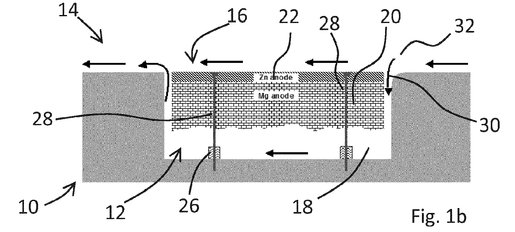
- Figure 1a shows a body 10 having a recess 12 located in a fluid washed surface 14.
- a sacrificial anode 16 is located within the recess such that it is surrounded by a channel 18.
- the channel 18 is formed by the anode 16 being located within the recess 12 and separated from its sides such that a fluid can flow around and contact the sides of the anode 16.
- the sacrificial anode 16 is constructed from a first material 20 and a second material 22.
- the first material 20 is more anodic than the second material 22 meaning that it has a higher anodic potential in a particular aqueous environment.
- the first material 20 is made from Magnesium and the second material 22 from Zinc and the body 10 is a steel structure and thus more cathodic than the first 20 and second materials 22 of the sacrificial anode 16.
- the electrolytic environment is provided by sea water. It will be appreciated that other anode-cathode material combinations are possible as exampled in table 1 below and that in some cases pure metals may be substituted with alloys which are commonly used for sacrificial anodes as known in the art.
- Table 1- A list of suitable anode combinations. Bimetallic anode pair Top surface of anode Bottom (bulk) of anode 1 Zinc Magnesium 2 Aluminium Zinc 3 Aluminium Magnesium 4 Mild steel Magnesium 5 Mild steel Zinc 6 Mild steel Aluminium
- the first 20 and second materials 22 are directly bonded together so as to prevent the ingress of water and allow a good electrical connection between the two. Providing a good electrical connection allows an electrical circuit to be formed out of the steel, the anode and the sea. This allows the corrosion of the preferential corrosion of the first material and thus protects the second material from corrosion until the second material has been consumed.
- There are numerous techniques which can be used to bond dissimilar metals together such as ultrasonic welding, diffusion bonding, brazing, rotary friction welding and fiction stir welding, to mention a few.
- the proportion of second material 22 to first material 20 will depend on the application but will be a balance between the expected amount of corrosion and the desired maintenance interval for example.
- the thickness of the second material 22 should be sufficient enough to be able to withstand mechanical damage which results from debris in the fluid flow and any hydrodynamic loads once the first material 20 has been consumed.
- the thickness ratio of the first material 20 to the second material will be approximately 1:9.
- the recess 12 is in the form of a well having straight sides and a flat bottom which is parallel to the fluid washed surface 14.
- Other shapes and configurations of recesses will be possible within the scope of the invention.
- the sacrificial anode 16 is mounted to the body 10 within the recess 12 on spacers in the form of pillars 26.
- the pillars 26 separate the anode 16 from the sides and bottom of the recess 12 within the body 10 so as to preserve the channel 18 which surrounds the anode 16.
- the size of the channel 18 will depend on the amount of fluid displacement required to provide satisfactory ionic exchange between the anode 16 and body 10.
- the sacrificial anode 16 is fixed to the body 10 using bolts 28 which pass through the apertures in the anode 16 which extend from an upper surface of the anode to the underside, through the pillars 26 and which engage with threaded bores within the body 10.
- the bolts 28 are metallic and provide an electrical connection between the anode 16 and the body 10. It will be apparent to the skilled person that the pillars 26 and bolts 28 are made from a non-corrosive material such that mechanical support can be maintained throughout the life of the anode 16.
- the anode 16 is mounted within the body 10 such that the upper surface of the anode 16 lies in approximately the same plane as the fluid washed surface. In this way, the hydrodynamic profile of the fluid washed surface can be maintained.
- An edge 30 of the body which is defined by the fluid washed surface and recess is rounded so as to have a curved profile which subtends at an angle of approximately 90° in the described embodiment. This feature encourages the flow of fluid through the channel 18 between the body 10 and anode 16, thus improving the flow of water around the anode, maintaining efficient operation. It will be appreciated that other features may be included to improve the flow of water in the channel 18.
- the body 10 is placed in a fluid flow (indicated by arrows 32) with the sacrificial anode 16 mounted a within the recess 12.
- the curved portion of the body 10 is placed upstream of the sacrificial anode 16 such that a flow of fluid is encouraged into the recess 12 and around the sacrificial anode 16.
- the presence of the seawater around the anode 16 and the galvanic relationship between the sacrificial anode 16 and the body 10 results in an electrochemical cell being set-up between the anode 16 and the body which prevent corrosion of the body 10 as described a bove.
- the ionic and electron flow results in the corrosion and consumption of the first of material 20 because it is more anodic than the body 10 and the second material 22. This is shown in Figure 1b where the first material 20 is partially corroded, but the second material 22 is preserved. Once the first material 20 has been completely consumed, the second material 22 then becomes the sacrificial anode as shown in Figure 1c and starts to corrode, while still providing protection to the body 10.
- the corrosion of the second material 22 only occurs after the first material 20 has been entirely consumed, this provides a clear indication that the anode 16 needs to be changed.
- a person carrying out maintenance to the body 10 can readily identify whether the anode 16 needs to be replaced by assessing the condition and amount of corrosion of the second material. This may include determining whether the corrosion is greater or less than a predetermined amount. The predetermined amount may be related to the physical dimensions of the second material or to the surface appearance. Further, in one embodiment, there may be markers embedded in the second layer which become exposed after a particular amount of corrosion. This system of maintenance would not be possible if the second material 22 corroded at the same time as the first material 20 which is not readily observable as it is located within the recess 12.
- Having a second material 22 which is less anodic than the first material 20 also means that it provides a protective layer for the fluid washed surface of the sacrificial anode 16. This means that the first material 20 corrodes from within the recess 12 and helps preserve the hydrodynamic profile of the body 10 and sacrificial anode 16.
- the clearance between the sacrificial anode 16 and the recess will be determined by the number of factors. For example, the salinity, temperature, and velocity of the fluid flow to name a few. Another important factor is the metal oxide which is formed as a part of the anode corrosion and dissolution process which will likely have a bigger volume than the parent metal and will partially fill the clearance round the anode. As will be appreciated, the volume of the oxide depends on the type of oxide formed and whether it is soluble or friable which may result in the oxide naturally eroding over time.
- the clearance is the same around all sides of the anode 16 and approximately between 10 and 20% of the minor dimension of the anode to account for possible variations in the oxide formation and maintain some water flow even under worst case conditions.
- the corresponding recess 12 in the body 10 should be approximately 11 to 12 cm deep and 42 to 44 cm long.
- a typical radius for the curved edge 30 of the recess in this case may be in the region of approximately 7 to 20 mm, depending on the operating environment.
- FIG. 2 shows a water jet propulsion unit 210 for a marine vessel which represents a typical example of an environment in which the sacrificial anode 212 of the invention may be used.
- the water jet includes a duct 214 having an inlet 216 for ingesting water, an outlet 218 for exhausting water so as to provide propulsion and a shaft driven impeller 220 arrangement for accelerating the water towards the outlet 218.
- the anode 212 can be seen as being recessed in a wall 222 of the duct 214.
- first and second layers are described as being electrically connected together, this is an optional feature which prevents the protective second layer from corroding until all of the first material has corroded.
- the second layer may be provided simply to protect the sacrificial anodic layer and maintain the hydrodynamic profile.
Landscapes
- Chemical & Material Sciences (AREA)
- Engineering & Computer Science (AREA)
- Materials Engineering (AREA)
- Mechanical Engineering (AREA)
- Metallurgy (AREA)
- Organic Chemistry (AREA)
- Prevention Of Electric Corrosion (AREA)
Abstract

Description
- This invention relates to a sacrificial anode. In particular, this invention relates to a sacrificial anode made from two materials, one material being higher galvanic series relative to the other.
- It is well known to use sacrificial anodes to prevent corrosion of metallic bodies in corrosive environments, such as sea water. Such sacrificial anodes are typically metallic members which are mounted local to or on the body they are to protect and are more susceptible to galvanic corrosion in the given environment in which they are located and thus more anodic. As the sacrificial anode is more anodic (less noble) than the metal of the parent structure a small localised electrochemical cell is set up between the anode and the body which is to be protected when placed in an electrolyte such as sea water. In this way, corrosion of the metallic body is reduced, if not entirely prevented. The anodes are sacrificial in that they corrode during the process and require periodic replacement.
- It is common practice to use surface mounted sacrificial anodes which are readily replaced when necessary. However, surface mounted sacrificial anodes represent a hydrodynamic penalty in the form of increased drag in conditions where the body is subjected to a constrained flow of water, such as a pipe or duct or in unconstrained flow such as on the rudder of a ship. The additional drag is generally undesirable.
- One option for overcoming the hydrodynamic penalty is to use an impressed current cathodic protection system which utilises a permanent (non consumable) anode through which a current is passed during operation. This has the advantage that the anode can have a much reduced profile and represents a lower hydrodynamic penalty. However, the complexity and cost of such a system is too high for many applications.
- The present invention seeks to provide a sacrificial anode which seeks to overcome some of the problems of the known systems.
- In a first aspect the present invention provides a sacrificial anode, comprising: a first layer of a first material; and, a second layer of a second material which is closely connected to the first layer, wherein the first material is more anodic with respect to a galvanic series than the second material.
- Providing a first and second material in this way provides a sacrificial anode in which can be recessed into a body whilst the underside of the anode corrodes and the upper side remains intact, thereby preserving the hydrodynamic shape of the body in which the anode is recessed.
- The first material and second material may be directly bonded together. The first material may be zinc. The second material may be magnesium. It will be appreciated, with reference to the electrochemical series, that other combinations of material may be used. The combinations of materials must ensure the galvanic relationship between the two is preserved such that the first material is more anodic than the second material. And, where the anode is recessed within a body, the second material is more anodic than the body.
- The ratio of the first material to the second material may be between approximately 1:5 and 1:12.
- In a second aspect, the present invention provides a metallic body comprising: a recess; and, the sacrificial anode as claimed in any preceding claim located within the recess and separated from the body by a channel, wherein the body is more cathodic with respect to a galvanic series than the first and second materials. The channel may substantially surrounds the anode.
- The recess may have an opening to a fluid flow in normal use. The opening may have a first dimension. The sacrificial anode may extend across up to 90% of the first dimension.
- The recess may be located in a fluid washed surface and a surface of the first material is located in the same plane as the fluid washed surface.
- At least one edge between the fluid washed surface and a surface of the recess may be shaped to encourage a flow of fluid into the recess.
- The at least one edge may have a curved profile which subtends between the fluid washed surface and surface of the recess.
- In a third aspect, the present invention provides a water jet propulsion unit comprising the body according to the second aspect.
- The body may form at least part of a duct through which water may be propelled when the propulsion unit is in normal use.
- In a fourth aspect, the present invention may provide a method of inspecting a sacrificial anode as claimed in claim any preceding claim, comprising: visually inspecting the first material; determining whether the corrosion of the first material is greater or lesser than a predetermined acceptable amount; and, replacing the anode if the corrosion of the first material is greater than the predetermined amount.
- Initiation of corrosion on the first material indicates consumption of the second material, indicating the need to replace the entire anode.
- Embodiments of the invention will now be described with the aid of the following drawings in which:
-
Figures 1a, b and c shows a sacrificial anode according to the present invention prior to, during and after a period of corrosion -
Figure 2 shows a water jet propulsion unit with a sacrificial anode. -
Figure 1a shows abody 10 having arecess 12 located in a fluid washedsurface 14. Asacrificial anode 16 is located within the recess such that it is surrounded by achannel 18. Thechannel 18 is formed by theanode 16 being located within therecess 12 and separated from its sides such that a fluid can flow around and contact the sides of theanode 16. - The
sacrificial anode 16 is constructed from afirst material 20 and asecond material 22. Thefirst material 20 is more anodic than thesecond material 22 meaning that it has a higher anodic potential in a particular aqueous environment. In the present embodiment, thefirst material 20 is made from Magnesium and thesecond material 22 from Zinc and thebody 10 is a steel structure and thus more cathodic than the first 20 andsecond materials 22 of thesacrificial anode 16. The electrolytic environment is provided by sea water. It will be appreciated that other anode-cathode material combinations are possible as exampled in table 1 below and that in some cases pure metals may be substituted with alloys which are commonly used for sacrificial anodes as known in the art.Table 1- A list of suitable anode combinations. Bimetallic anode pair Top surface of anode Bottom (bulk) of anode 1 Zinc Magnesium 2 Aluminium Zinc 3 Aluminium Magnesium 4 Mild steel Magnesium 5 Mild steel Zinc 6 Mild steel Aluminium - The first 20 and
second materials 22 are directly bonded together so as to prevent the ingress of water and allow a good electrical connection between the two. Providing a good electrical connection allows an electrical circuit to be formed out of the steel, the anode and the sea. This allows the corrosion of the preferential corrosion of the first material and thus protects the second material from corrosion until the second material has been consumed. There are numerous techniques which can be used to bond dissimilar metals together such as ultrasonic welding, diffusion bonding, brazing, rotary friction welding and fiction stir welding, to mention a few. - The proportion of
second material 22 tofirst material 20 will depend on the application but will be a balance between the expected amount of corrosion and the desired maintenance interval for example. The thickness of thesecond material 22 should be sufficient enough to be able to withstand mechanical damage which results from debris in the fluid flow and any hydrodynamic loads once thefirst material 20 has been consumed. Typically, the thickness ratio of thefirst material 20 to the second material will be approximately 1:9. However, the skilled person will appreciate that it may be preferential to have a range between 1:5 and 1:12. - The
recess 12 is in the form of a well having straight sides and a flat bottom which is parallel to the fluid washedsurface 14. However, other shapes and configurations of recesses will be possible within the scope of the invention. - The
sacrificial anode 16 is mounted to thebody 10 within therecess 12 on spacers in the form ofpillars 26. Thepillars 26 separate theanode 16 from the sides and bottom of therecess 12 within thebody 10 so as to preserve thechannel 18 which surrounds theanode 16. The size of thechannel 18 will depend on the amount of fluid displacement required to provide satisfactory ionic exchange between theanode 16 andbody 10. - The
sacrificial anode 16 is fixed to thebody 10 usingbolts 28 which pass through the apertures in theanode 16 which extend from an upper surface of the anode to the underside, through thepillars 26 and which engage with threaded bores within thebody 10. Thebolts 28 are metallic and provide an electrical connection between theanode 16 and thebody 10. It will be apparent to the skilled person that thepillars 26 andbolts 28 are made from a non-corrosive material such that mechanical support can be maintained throughout the life of theanode 16. - Providing an electrical connection between the anode and the body in this way allows an electron flow between the
body 10 andanode 16 in use. Thus, there is an ionic flow between the anode and the body through the sea water and an electron flow through thebolts 28. It will be appreciated that the electrical connection can be made in other ways as known in the art. - The
anode 16 is mounted within thebody 10 such that the upper surface of theanode 16 lies in approximately the same plane as the fluid washed surface. In this way, the hydrodynamic profile of the fluid washed surface can be maintained. - An
edge 30 of the body which is defined by the fluid washed surface and recess is rounded so as to have a curved profile which subtends at an angle of approximately 90° in the described embodiment. This feature encourages the flow of fluid through thechannel 18 between thebody 10 andanode 16, thus improving the flow of water around the anode, maintaining efficient operation. It will be appreciated that other features may be included to improve the flow of water in thechannel 18. - In use, the
body 10 is placed in a fluid flow (indicated by arrows 32) with thesacrificial anode 16 mounted a within therecess 12. The curved portion of thebody 10 is placed upstream of thesacrificial anode 16 such that a flow of fluid is encouraged into therecess 12 and around thesacrificial anode 16. The presence of the seawater around theanode 16 and the galvanic relationship between thesacrificial anode 16 and thebody 10 results in an electrochemical cell being set-up between theanode 16 and the body which prevent corrosion of thebody 10 as described a bove. - The ionic and electron flow results in the corrosion and consumption of the first of
material 20 because it is more anodic than thebody 10 and thesecond material 22. This is shown inFigure 1b where thefirst material 20 is partially corroded, but thesecond material 22 is preserved. Once thefirst material 20 has been completely consumed, thesecond material 22 then becomes the sacrificial anode as shown inFigure 1c and starts to corrode, while still providing protection to thebody 10. - Because the corrosion of the
second material 22 only occurs after thefirst material 20 has been entirely consumed, this provides a clear indication that theanode 16 needs to be changed. Thus, a person carrying out maintenance to thebody 10 can readily identify whether theanode 16 needs to be replaced by assessing the condition and amount of corrosion of the second material. This may include determining whether the corrosion is greater or less than a predetermined amount. The predetermined amount may be related to the physical dimensions of the second material or to the surface appearance. Further, in one embodiment, there may be markers embedded in the second layer which become exposed after a particular amount of corrosion. This system of maintenance would not be possible if thesecond material 22 corroded at the same time as thefirst material 20 which is not readily observable as it is located within therecess 12. - Having a
second material 22 which is less anodic than thefirst material 20 also means that it provides a protective layer for the fluid washed surface of thesacrificial anode 16. This means that thefirst material 20 corrodes from within therecess 12 and helps preserve the hydrodynamic profile of thebody 10 andsacrificial anode 16. - The skilled person will appreciate that the clearance between the
sacrificial anode 16 and the recess will be determined by the number of factors. For example, the salinity, temperature, and velocity of the fluid flow to name a few. Another important factor is the metal oxide which is formed as a part of the anode corrosion and dissolution process which will likely have a bigger volume than the parent metal and will partially fill the clearance round the anode. As will be appreciated, the volume of the oxide depends on the type of oxide formed and whether it is soluble or friable which may result in the oxide naturally eroding over time. - In one embodiment, the clearance is the same around all sides of the
anode 16 and approximately between 10 and 20% of the minor dimension of the anode to account for possible variations in the oxide formation and maintain some water flow even under worst case conditions. For example, for an anode which is 10cm thick and 40 cm long, the correspondingrecess 12 in thebody 10 should be approximately 11 to 12 cm deep and 42 to 44 cm long. A typical radius for thecurved edge 30 of the recess in this case may be in the region of approximately 7 to 20 mm, depending on the operating environment. -
Figure 2 shows a waterjet propulsion unit 210 for a marine vessel which represents a typical example of an environment in which thesacrificial anode 212 of the invention may be used. The water jet includes aduct 214 having aninlet 216 for ingesting water, anoutlet 218 for exhausting water so as to provide propulsion and a shaft drivenimpeller 220 arrangement for accelerating the water towards theoutlet 218. Theanode 212 can be seen as being recessed in awall 222 of theduct 214. - The above described embodiments are examples of the invention defined by the claims and should not be taken as limiting. For example, although the first and second layers are described as being electrically connected together, this is an optional feature which prevents the protective second layer from corroding until all of the first material has corroded. The second layer may be provided simply to protect the sacrificial anodic layer and maintain the hydrodynamic profile.
Claims (13)
- A metallic body comprising:a sacrificial anode located within a recess of the metallic body, the sacrificial anode comprising:a first layer of a first material; and,a second layer of a second material which is located proximate to the first layer, wherein the first material is more anodic with respect to a galvanic series than the second material,wherein the sacrificial anode is separated from the body by a channel and electrically connected thereto, wherein the body is more cathodic with respect to a galvanic series than the first and second materials; and,wherein the recess is located in a fluid washed surface of the body and a surface of the first material is located in the same plane as the fluid washed surface.
- A metallic body as claimed in claim 1 wherein the channel substantially surrounds the anode.
- A metallic body as claimed in claims 1 or 2 wherein the recess has an opening to a fluid flow in normal use, the opening having a first dimension, wherein the sacrificial anode extends across up to 90% of the first dimension.
- A metallic body as claimed in any of claims 1 to 3 wherein at least one edge between the fluid washed surface and a surface of the recess is shaped to encourage a flow of fluid into the recess.
- A metallic body as claimed in claim 4 wherein the at least one edge has a curved profile which subtends between the fluid washed surface and surface of the recess.
- A metallic body as claimed in claim 1 wherein the first layer and second layer are electrically connected together.
- A metallic body as claimed in any preceding claim wherein the first layer and second layer are directly bonded together.
- A metallic body as claimed in any preceding claim wherein the first material is magnesium.
- A metallic body as claimed in claim 4 wherein the second material is zinc.
- A metallic body as claimed in any preceding claim wherein the ratio of the first material to the second material is between approximately 1:5 and 1:12.
- A water jet propulsion unit comprising the body as claimed in any of claims 1 to 10.
- A water jet propulsion unit as claimed in claim 11 wherein the body forms at least part of a duct through which water is propelled when the propulsion unit is in normal use.
- A method of inspecting a sacrificial anode of the metallic body as claimed in claim any preceding claim, comprising:visually inspecting the second material;determining whether the corrosion of the second material is greater or lesser than a predetermined acceptable amount; and,replacing the anode if the corrosion of the second material is greater than the predetermined amount.
Applications Claiming Priority (1)
| Application Number | Priority Date | Filing Date | Title |
|---|---|---|---|
| GBGB1119446.1A GB201119446D0 (en) | 2011-11-11 | 2011-11-11 | A sacrificial anode |
Publications (2)
| Publication Number | Publication Date |
|---|---|
| EP2592175A2 true EP2592175A2 (en) | 2013-05-15 |
| EP2592175A3 EP2592175A3 (en) | 2017-02-01 |
Family
ID=45421594
Family Applications (1)
| Application Number | Title | Priority Date | Filing Date |
|---|---|---|---|
| EP12189511.4A Withdrawn EP2592175A3 (en) | 2011-11-11 | 2012-10-23 | A sacrificial anode |
Country Status (3)
| Country | Link |
|---|---|
| US (1) | US9045834B2 (en) |
| EP (1) | EP2592175A3 (en) |
| GB (1) | GB201119446D0 (en) |
Cited By (7)
| Publication number | Priority date | Publication date | Assignee | Title |
|---|---|---|---|---|
| CN105501389A (en) * | 2016-01-20 | 2016-04-20 | 英辉南方造船(广州番禺)有限公司 | Embedded ship shell sacrificial anode and installing method thereof |
| EP3020851A1 (en) * | 2014-11-17 | 2016-05-18 | Rolls-Royce plc | A marine cathodic protection system |
| EP3023728A4 (en) * | 2013-10-31 | 2017-05-03 | Mitsubishi Electric Corporation | Corrosion resistance life diagnosis component, heat exchanger, and refrigeration and air conditioning device |
| WO2017149030A1 (en) * | 2016-03-03 | 2017-09-08 | Vetco Gray Scandinavia As | System and method for cathodic protection by distributed sacrificial anodes |
| WO2018095548A1 (en) * | 2016-11-28 | 2018-05-31 | Schottel Gmbh | Nozzle of a ship propeller |
| CN110855751A (en) * | 2019-10-21 | 2020-02-28 | 同济大学 | Segmented concealed buried pipeline cathodic protection status monitoring and early warning system and method |
| WO2020152384A1 (en) * | 2019-01-23 | 2020-07-30 | Industrias Ramon Soler, S. A. | Tap with exterior galvanic protection |
Families Citing this family (2)
| Publication number | Priority date | Publication date | Assignee | Title |
|---|---|---|---|---|
| JP5789310B2 (en) * | 2014-01-28 | 2015-10-07 | 株式会社新来島どっく | Anode mounting structure with hull skin |
| CN114799482A (en) * | 2022-05-19 | 2022-07-29 | 长江师范学院 | Friction welding process for magnesium alloy sacrificial anode rod for water heater |
Family Cites Families (13)
| Publication number | Priority date | Publication date | Assignee | Title |
|---|---|---|---|---|
| GB980860A (en) | 1960-06-29 | 1965-01-20 | Cathodic Corposion Control Ltd | Improvements relating to the electrolytic protection against corrosion of a metallicstructure |
| US3891530A (en) | 1972-11-29 | 1975-06-24 | Perfection Corp | Anode-fitting assembly |
| US4604068A (en) * | 1984-09-10 | 1986-08-05 | Outboard Marine Corporation | Marine propulsion device lower unit including propeller bearing member anode |
| US5342228A (en) * | 1992-05-27 | 1994-08-30 | Brunswick Corporation | Marine drive anode |
| JP2735792B2 (en) | 1994-07-22 | 1998-04-02 | 株式会社日本アルミ | Method for corrosion protection of aluminum material and sacrificial anode for corrosion protection of aluminum material |
| JPH0995790A (en) * | 1995-10-02 | 1997-04-08 | Hitachi Zosen Corp | Anode metal mounting structure |
| JPH09189226A (en) * | 1995-12-30 | 1997-07-22 | Sanshin Ind Co Ltd | Anti-corrosion device for overboard machine |
| KR100643005B1 (en) | 2003-07-18 | 2006-11-10 | 한국전기연구원 | Hybrid anode structure for electric system |
| US7329336B2 (en) | 2006-04-20 | 2008-02-12 | Deepwater Corrosion Services, Inc. | Stabilizer with cathodic protection |
| CN201372311Y (en) | 2009-03-20 | 2009-12-30 | 武汉市环宇防腐有限公司 | Composite sacrificial anode structure |
| JP5150549B2 (en) * | 2009-04-06 | 2013-02-20 | 本田技研工業株式会社 | Sacrificial electrode mounting structure |
| US8268134B2 (en) | 2010-05-21 | 2012-09-18 | General Electric Company | System for protecting turbine engine surfaces from corrosion |
| US20110308967A1 (en) * | 2010-06-17 | 2011-12-22 | S.P.M. Flow Control, Inc. | Pump Cavitation Device |
-
2011
- 2011-11-11 GB GBGB1119446.1A patent/GB201119446D0/en not_active Ceased
-
2012
- 2012-10-22 US US13/657,288 patent/US9045834B2/en active Active
- 2012-10-23 EP EP12189511.4A patent/EP2592175A3/en not_active Withdrawn
Non-Patent Citations (1)
| Title |
|---|
| None * |
Cited By (12)
| Publication number | Priority date | Publication date | Assignee | Title |
|---|---|---|---|---|
| EP3023728A4 (en) * | 2013-10-31 | 2017-05-03 | Mitsubishi Electric Corporation | Corrosion resistance life diagnosis component, heat exchanger, and refrigeration and air conditioning device |
| EP3020851A1 (en) * | 2014-11-17 | 2016-05-18 | Rolls-Royce plc | A marine cathodic protection system |
| US9790601B2 (en) | 2014-11-17 | 2017-10-17 | Rolls-Royce Plc | Marine cathodic protection system |
| CN105501389A (en) * | 2016-01-20 | 2016-04-20 | 英辉南方造船(广州番禺)有限公司 | Embedded ship shell sacrificial anode and installing method thereof |
| WO2017149030A1 (en) * | 2016-03-03 | 2017-09-08 | Vetco Gray Scandinavia As | System and method for cathodic protection by distributed sacrificial anodes |
| CN109154089A (en) * | 2016-03-03 | 2019-01-04 | 韦特柯格雷斯堪的纳维亚有限公司 | System and method for cathodic protection by distributed sacrificial anodes |
| WO2018095548A1 (en) * | 2016-11-28 | 2018-05-31 | Schottel Gmbh | Nozzle of a ship propeller |
| CN110023187A (en) * | 2016-11-28 | 2019-07-16 | 施奥泰尔有限公司 | The diversion pipe of marine propeller |
| CN110023187B (en) * | 2016-11-28 | 2021-06-15 | 施奥泰尔有限公司 | The draft tube of the ship's propulsion |
| WO2020152384A1 (en) * | 2019-01-23 | 2020-07-30 | Industrias Ramon Soler, S. A. | Tap with exterior galvanic protection |
| CN110855751A (en) * | 2019-10-21 | 2020-02-28 | 同济大学 | Segmented concealed buried pipeline cathodic protection status monitoring and early warning system and method |
| CN110855751B (en) * | 2019-10-21 | 2021-09-03 | 同济大学 | Segmented hidden buried pipeline cathode protection state monitoring and early warning system and method |
Also Published As
| Publication number | Publication date |
|---|---|
| US9045834B2 (en) | 2015-06-02 |
| NZ603335A (en) | 2014-04-30 |
| US20130118915A1 (en) | 2013-05-16 |
| GB201119446D0 (en) | 2011-12-21 |
| EP2592175A3 (en) | 2017-02-01 |
Similar Documents
| Publication | Publication Date | Title |
|---|---|---|
| US9045834B2 (en) | Sacrificial anode | |
| Xu et al. | Challenges and solutions of cathodic protection for marine ships | |
| Bardal | Corrosion and protection | |
| WO2015045608A1 (en) | Electrolytic protection system and pump device provided with same | |
| US20110300395A1 (en) | Corrosion Protection System for Offshore Steel Structures and a Method for its Application | |
| Jasionowski et al. | Cavitation erosion resistance of alloys used in cathodic protection of hulls of ships | |
| EP3020851B1 (en) | A marine cathodic protection system | |
| NZ603335B (en) | A Sacrificial Anode | |
| JP3681123B2 (en) | Filter | |
| JP5162759B2 (en) | Ship UEP reduction method and apparatus | |
| JP2018173032A (en) | Remaining life prediction method of pump, sacrificial anode, sacrificial anode | |
| US4468310A (en) | Aluminum marine anode with core activator | |
| JP5047395B1 (en) | Corrosion-proof aluminum alloy galvanic anode with no corrosion products | |
| Walsh et al. | Corrosion and protection of metals: II. Types of corrosion and protection methods | |
| US3179582A (en) | Welding attachment of anodes for cathodic protection | |
| JP5402177B2 (en) | The galvanic anode body and the galvanic anode method | |
| Spacht | The corrosion resistance of aluminum and its alloys. | |
| JP2001041140A (en) | Impeller for hydraulic machine and hydraulic machine | |
| US4191625A (en) | Aluminum marine anode assembly with low resistance surface mountings | |
| US20080107560A1 (en) | Alloy for use in galvanic protection | |
| RU191508U1 (en) | FLOATING MARINE OBJECT | |
| JP2012046063A (en) | Method and apparatus for reducing uep of hull | |
| JP2000129474A (en) | Hydrogen absorption embrittlement buffering method for titanium clad steel | |
| Ismail et al. | Justification and Judgement to Corrosion Issues for Anode Selections on Navy ships | |
| JPH0346305B2 (en) |
Legal Events
| Date | Code | Title | Description |
|---|---|---|---|
| PUAI | Public reference made under article 153(3) epc to a published international application that has entered the european phase |
Free format text: ORIGINAL CODE: 0009012 |
|
| AK | Designated contracting states |
Kind code of ref document: A2 Designated state(s): AL AT BE BG CH CY CZ DE DK EE ES FI FR GB GR HR HU IE IS IT LI LT LU LV MC MK MT NL NO PL PT RO RS SE SI SK SM TR |
|
| AX | Request for extension of the european patent |
Extension state: BA ME |
|
| RAP1 | Party data changed (applicant data changed or rights of an application transferred) |
Owner name: ROLLS-ROYCE PLC |
|
| PUAL | Search report despatched |
Free format text: ORIGINAL CODE: 0009013 |
|
| RIC1 | Information provided on ipc code assigned before grant |
Ipc: B63B 59/04 20060101ALI20161222BHEP Ipc: C23F 13/16 20060101AFI20161222BHEP Ipc: C23F 13/22 20060101ALI20161222BHEP |
|
| AK | Designated contracting states |
Kind code of ref document: A3 Designated state(s): AL AT BE BG CH CY CZ DE DK EE ES FI FR GB GR HR HU IE IS IT LI LT LU LV MC MK MT NL NO PL PT RO RS SE SI SK SM TR |
|
| AX | Request for extension of the european patent |
Extension state: BA ME |
|
| STAA | Information on the status of an ep patent application or granted ep patent |
Free format text: STATUS: REQUEST FOR EXAMINATION WAS MADE |
|
| 17P | Request for examination filed |
Effective date: 20170728 |
|
| RBV | Designated contracting states (corrected) |
Designated state(s): AL AT BE BG CH CY CZ DE DK EE ES FI FR GB GR HR HU IE IS IT LI LT LU LV MC MK MT NL NO PL PT RO RS SE SI SK SM TR |
|
| STAA | Information on the status of an ep patent application or granted ep patent |
Free format text: STATUS: EXAMINATION IS IN PROGRESS |
|
| 17Q | First examination report despatched |
Effective date: 20190222 |
|
| RAP1 | Party data changed (applicant data changed or rights of an application transferred) |
Owner name: ROLLS-ROYCE PLC |
|
| STAA | Information on the status of an ep patent application or granted ep patent |
Free format text: STATUS: THE APPLICATION IS DEEMED TO BE WITHDRAWN |
|
| 18D | Application deemed to be withdrawn |
Effective date: 20200715 |