EP2592013A1 - Bouteille à boisson munie d'une fermeture refermable dotée d'un axe de came - Google Patents
Bouteille à boisson munie d'une fermeture refermable dotée d'un axe de came Download PDFInfo
- Publication number
- EP2592013A1 EP2592013A1 EP11188428.4A EP11188428A EP2592013A1 EP 2592013 A1 EP2592013 A1 EP 2592013A1 EP 11188428 A EP11188428 A EP 11188428A EP 2592013 A1 EP2592013 A1 EP 2592013A1
- Authority
- EP
- European Patent Office
- Prior art keywords
- periphery
- bulge
- skirt part
- skirt
- cam
- Prior art date
- Legal status (The legal status is an assumption and is not a legal conclusion. Google has not performed a legal analysis and makes no representation as to the accuracy of the status listed.)
- Ceased
Links
Images


Classifications
-
- B—PERFORMING OPERATIONS; TRANSPORTING
- B65—CONVEYING; PACKING; STORING; HANDLING THIN OR FILAMENTARY MATERIAL
- B65D—CONTAINERS FOR STORAGE OR TRANSPORT OF ARTICLES OR MATERIALS, e.g. BAGS, BARRELS, BOTTLES, BOXES, CANS, CARTONS, CRATES, DRUMS, JARS, TANKS, HOPPERS, FORWARDING CONTAINERS; ACCESSORIES, CLOSURES, OR FITTINGS THEREFOR; PACKAGING ELEMENTS; PACKAGES
- B65D51/00—Closures not otherwise provided for
- B65D51/24—Closures not otherwise provided for combined or co-operating with auxiliary devices for non-closing purposes
- B65D51/243—Closures not otherwise provided for combined or co-operating with auxiliary devices for non-closing purposes combined with an opening device
Definitions
- the present invention relates to a beverage bottle having a re-sealable closure and a method of applying and interlocking a re-sealable closure for a beverage bottle.
- crown corks Metallic caps, generally known as crown corks, have been frequently used for sealing glass beverage bottles ever since their introduction in the late 19 th century.
- Crown corks comprise a metallic cap having parts arranged for engagement with the external periphery of a neck or wall of the beverage bottle.
- crown corks are applied onto standard glass bottles having an outwardly oriented bulge near the mouth of the bottle. The crown cork is clamped securely onto the bulge in order to withstand and seal the pressure within the bottle.
- the generally known crown corks are made of thin metal sheet and have the advantage of being easy to manufacture, require a very small amount of material and they are easy to apply onto the mouth of the beverage bottle. Crown corks are also tamper evident, since once the crown cork is removed, it cannot easily be re-applied onto the bottle.
- the original crown corks are described in US 468,226 and US 468,258 .
- lever lock concept which may be defined as a closure comprising a cap and a lever pivotally connected to the perimeter of the cap
- the cap has a skirt for effecting a partial engagement with a flange on a neck of a bottle and the lever has a surface at its pivoted end, which surface, in one pivotal position, defines a locking position, engages the flange on the bottle neck, thereby complementing the partial engagement of the skirt for retaining the cap on the bottle, and in another pivotal position, defining a releasing position, disengages the flange for allowing the cap to be removed from the bottle against the partial engagement of the skirt.
- the lever when in the locking position, may be flushed with the top surface of the cap (lever lock (a)), or may extend parallel to the neck of the bottle (lever lock (b)).
- the pivotal connection between the lever and the cap may be a mechanical hinge or a living hinge, i.e. a thin flexible web of material joining the lever and the cap together.
- EP 2 262 696 published in 2010 , discloses a closure including a cap cover and a pivoting part pivotally connected to the perimeter of the cap cover.
- the pivoting part includes an engagement structure for engaging a flange on a bottle neck when the pivoting part is in a first pivotal position.
- a reference showing an alternative position of the lever when in the locked position is FR 1 539 832, published in 1968 , which discloses a bottle closure having a ring connected to the periphery of a cap, the ring, upon lifting, causing the bead connected with the ring to disengage the flange of a bottle.
- FR 2 432 450 published in 1980 , which discloses a cap having a lever pivotally attached to the periphery of the cap, the lever including at its pivoting end a surface for in one pivotal position engaging a flange on a bottle neck, see the figure below.
- WO2001/068467 discloses a closure having a lever pivotally attached by means of a hinge to a cap.
- the lever further has a tooth for engaging the flange of a bottle neck.
- the European patent EP 636 093 discloses a bottle cap having a lever pivotally attached to the periphery of the cap. Manipulation of the lever causes a flange engaging element to disengage a flange of the bottle.
- closure according to the present invention may be applied onto the mouth of the bottle by a very simple capping operation similar to that of ordinary crown corks.
- a beverage bottle having a re-sealable closure comprising a body, a cylindrical neck connected to the body and a mouth connected to the neck opposite the body and defining an opening, the mouth comprising an outwardly oriented bulge at a first axial distance from the opening, the bulge defining a first outer periphery at the first axial distance, the closure comprising:
- the beverage bottle is a standard bottle having a body intended to accommodate the beverage, typically in an amount of between 25cl and 1 litre, and a neck leading to the mouth and the opening of the bottle.
- the bottle is typically made of glass.
- the outwardly oriented bulge is typically rounded and defines a circumference larger than the neck and defines a "saddle" between the bulge and the neck.
- the first outer periphery is understood to be the largest periphery of the bulge and is located an axial distance from the opening.
- the neck may optionally define further bulges below the bulge closest to the opening, which bulges may be used for other purposes such as fastening a tamper evident ring.
- the cap covers the opening and seals the opening in relation to the outside environment.
- the first skirt part extends the second axial distance from the opening to a location below the first periphery defining the third part periphery such that the first skirt part interlocks with the outwardly oriented bulge at the "saddle" between the outwardly oriented bulge and the neck.
- the first skirt part may optionally be corrugated in an axial direction and in such cases the number of corrugations typically is between 5 and 20, such as 10.
- the first skirt part may extend between 90 degrees and 270 degrees around the first periphery, preferably between 120 degrees and 240 degrees, more preferably between 150 degrees and 210 degrees, such as 180 degrees.
- the second and third skirt parts are not interlocked with the outwardly oriented bulge and extend in substantially tangential directions from the sides of the first skirt part, which interconnect the first part periphery and the second part periphery.
- the second and third skirt parts serve the purpose of establishing opposing bearings to hold the cam axle.
- the cam axle is rotatable about the journaling axis.
- the first cam surface When the closure is in its closed position, i.e. the first position, the first cam surface interlocks with the outwardly oriented bulge of the beverage bottle.
- the first cam surface is preferably rounded in order to fit in the "saddle" established by the outwardly oriented bulge and the neck of the beverage bottle.
- the cam axle When the cam axle is turned about the journaling axis to the open or second position such that the second cam surface is facing the bulge, the cam axle slips out of the "saddle".
- the second cam surface is preferably flat in order to not be able to fit in the "saddle” but slipping past it.
- the cam axle may be turned as much as 180 degrees, however, in some cases 90 degrees may be sufficient for turning the first cam surface away from the bulge and the second cam surface towards the bulge.
- the pressure within the beverage bottle caused by carbonated beverages is released when the cam axle is turned to the open state.
- the closure may then be detached from the mouth of the beverage bottle by lifting the cam axle in an upwards direction and subsequently allowing the first skirt part to be released from the outwardly oriented bulge.
- the closure may then be reapplied by reversing the above procedure, i.e by first attaching the first skirt part in an interlocking position relative to the outwardly oriented bulge, then pressing the cam axle downwardly such that it is located in a juxtaposed position relative to the outwardly oriented bulge and finally turning the cam axle to the closed position, thereby interlocking the first cam surface and the outwardly oriented bulge.
- the cap, the first skirt part, the second skirt part and the third skirt part are made of metal, while the cam axle is made of a polymeric material.
- the first, second and third skirt parts should be sufficiently rigid in order to not bend due to the pressure within the beverage bottle.
- the cam axle may be made of a polymeric material in order to reduce the friction between the cam axle and the outwardly oriented bulge.
- the cam axle and the journaling axis are flexible to enable rotation of the cam.
- the cam axle may be flexible and the journaling axis may be curved.
- the cam axle is including slots being perpendicular to the journaling axis to enable rotation of the cam.
- the cam axle including both the first cam surface and the second cam surface may include slots which are open in the direction facing away from the bulge and closed in the direction facing towards the bulge.
- the cam axle is connected to a pivotable handle. In order to simplify the rotation of the cam axle, it may be connected to a handle
- the handle is flexible.
- the handle may be flexible in order for the journaling axis to be curved.
- the pivotable handle in the first position, is being located adjacent the disc of the cap or alternatively, the pivotable handle, in the first position, is being oriented substantially perpendicular to the disc of the cap.
- the handle may be used for showing a commercial message such as a logo-type.
- the handle may be located vertically, i.e. perpendicular to the disc or along the neck of the bottle.
- the cam axle comprises a third cam surface defining a sixth part periphery being smaller than the first outer periphery of the bulge, when in the second position, the third cam surface interlocks with the bulge.
- the closure upon operating the handle into the second position, i.e. the open state, will remove the closure from the opening of the bottle, but retain the closure in a degassing state adjacent the opening in which state the third cam surface is interlocking with the bulge.
- the closure is completely removed by operating the handle slightly towards the first position, i.e. the closed state, thereby disengaging the third cam surface and the bulge.
- the cam is capable of subjecting the mouth to a force of between 500 and 5000N, preferably between 1000 and 2000N, more preferably between 1200 and 1500N, such as 1360N Such forces are sufficient for keeping the closure in place even for carbonated beverages.
- the cap, the first skirt part, the second skirt part and the third skirt part are made by progression tooling
- the cap, the first skirt part, the second skirt part and the third skirt part are having a thickness of between 0.16 and 0.50mm, preferably between 0.20 and 0.30mm, such as 0,25mm.
- the skirt is typically slightly thicker than for standard crown corks in order to ensure that the skirt cannot easily deform.
- the closure further includes a fourth skirt located between the second skirt and the third skirt for enclosing the cam axle.
- the cam axle may be protected and optionally clamped against the saddle.
- the second skirt part and the third skirt part define grooves for accommodating the cam axle.
- the grooves may constitute bearings for the cam axle.
- the closure is pivotably attached to the neck of the bottle. In order to not loose the closure after opening the closure, it may be pivotably attached to the bottle.
- a re-sealable closure for a beverage bottle comprising a body, a cylindrical neck connected to the body and a mouth connected to the neck opposite the body and defining an opening, the mouth comprising an outwardly oriented bulge at a first axial distance from the opening, the bulge defining a first outer periphery at the first axial distance, the closure comprising:
- the above method according to the second aspect may advantageously be used for applying a closure to a bottle according to the first aspect of the present invention.
- the above method has the advantage that the cam axle may be applied in the closed or second state. In this way there is no need for closing the cam axle during the capping, i.e. the application of the closure onto the beverage bottle, thus making the capping operation much simpler.
- the closure is applied such that the first cam surface is interlocking with the outwardly oriented bulge and the first skirt part is located outside the "saddle" established by the outwardly oriented bulge such that the third part periphery is larger than the first part periphery.
- the first skirt part is clamped inwardly for interlocking with the outwardly oriented bulge.
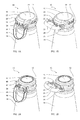
- Fig. 1A shows a first embodiment of a closure 10 being fastened to a beverage bottle according to the present invention.
- the closure is fastened onto an outwardly oriented bulge 12 of a bottle neck 14.
- the bulge 12 surrounds an opening (presently not shown but designated the reference numeral 32 in fig 2A ) of the beverage bottle.
- the bottle neck 14 forms part of a beverage bottle for carbonated beverage, in particular a beer bottle.
- the closure 10, which is made of thin metal sheet having a thickness of about 0.25 mm, comprises a disc 16 for covering the opening of the beverage bottle and a first skirt part 18 extending from the disc 16 and interlocking with the outwardly oriented bulge 12 of the bottle neck 14.
- the first skirt part is corrugated and bent inwardly at the "saddle" established in the transition between the outwardly oriented bulge 12 and the bottle neck 14 in order to define a partial periphery being smaller than the outermost periphery of the bulge 12.
- the closure 10 further comprises a second skirt part 20 and a third skirt part 22 extending from the opposing sides of the first skirt part 18.
- the second skirt part 20 and the third skirt part 22 define part peripheries being larger than the first part periphery 18 and larger than the periphery of the outwardly oriented bulge 12 of the bottle neck 14 and thereby do not contribute to the fastening of the closure 10 onto the bulge 12.
- the closure 10 further comprises a fourth skirt part 24 being corrugated and interconnecting the second skirt part 20 and the third skirt part 22 and defining a part periphery being larger than the periphery of the outwardly oriented bulge 12.
- the fourth skirt part 24 and the outwardly oriented bulge 12 define a spacing between themselves and the fourth skirt part 24 thereby does not contribute to the fastening of the closure 10.
- the closure 10 further comprises an extension part 26 interconnecting the disc 16, the second skirt 20, the third skirt part 22 and the fourth skirt part 24.
- the second skirt part 20 and the third skirt part 22 are typically non-corrugated but define opposing bearings 28 28', each bearing 28 28' being constituted by a cavity.
- the closure 10 further comprises a handle 30.
- the handle 30 is located in a first position along the bottle neck 14 defining a closed state.
- Fig. 1B shows a first embodiment of a closure 10 being fastened to a beverage bottle according to the present invention.
- the handle 30 has been lifted to a second position defining an open state which will be discussed in more detail below.
- Fig. 2A shows a cut out perspective view of the closure according to the present invention, similar to fig 1A except that the disc, the extension part and the first, second, third and fourth skirt have been removed for revealing a journaling axis comprising a cam axle 34.
- the cam axle 34 is rotatably held by the opposing bearings of the second and third skirts.
- the handle 30 is fixedly connected to the cam axle 34 and is presently in the closed state. By rotating the handle 30, the cam axle 34 is rotated as well.
- the cam axle comprises a first cam surface (not visible here but designated the reference numeral 40 in fig 2B ) which is in the present closed state is facing the saddle between the bulge 12 and the bottle neck 14 and therefore not visible.
- the first cam surface is rounded and defines a first distance from the journaling axis and a part periphery being smaller than the periphery of the bulge 12 in order to fit in the "saddle" between the bulge 12 and the bottle neck 14 and thereby interlock with the bulge 12.
- the cam axle 34 further comprises a second cam surface 40 which is flat and defines a second distance from the journaling axis, which is smaller than the first distance of the first cam surface, and a part periphery which is equal to or larger than the periphery of the bulge 12.
- the cam axle 34 comprises slots 36, which allow the cam axle to rotate while assuming a curvature corresponding to the curvature of the outwardly oriented bulge 12 of the beverage battle. When the closure 10 is in the present closed state the slots 36 are open at the second cam surface 40 in order to assume a larger curvature but closed at the first cam surface (not visible) in order to assume a smaller curvature.
- Fig. 2A shows a cut out perspective view of the closure according to the present invention, similar to fig 1B except that the disc, the extension part and the first, second, third and fourth skirt has been removed for revealing a journaling axis comprising a cam axle 34.
- the handle 30 has now been rotated to the open state, thereby rotating the cam axle 34 so that the first surface 40 is facing outwardly and the second surface (not visible) is facing inwardly.
- the second cam surface has a flat shape and the second distance of the second cam surface is smaller than the first distance of the first cam surface 38 in order to assume an equal or larger part periphery compared to the periphery of the bulge 12 so that the cam axle may slip past the bulge 12.
- the slots 36 are open at the first cam surface 38 in order to assume a larger curvature, but closed at the second cam surface (not visible) in order to assume a smaller curvature.
- Fig. 3A shows a second embodiment of the closure 10' having a handle 30' being flush with the disc 16' in the closed state.
- the first cam surface 38' of the cam axle 34' is interlocking with the bulge 12 at the transition between the bulge 12 and the bottle neck 14.
- the handle 30' has an L-shape.
- the skirt 18' interlocks with the bulge 12 opposite the cam axle 34'.
- Fig. 3B shows the second embodiment of the closure 10' having a handle 30' which has been listed above the disc 16' in the open state, thereby rotating the cam axle 34' causing the first cam surface 38' to be oriented away from the bulge 12 and the second cam surface 40' to be facing the bulge 12.
- the second cam surface 40' defines a smaller radius relative to the journaling axis 34' than the first cam surface 38' and thus allows the cam axle 34' to slip past the second cam surface 40'
- Fig. 3C shows an optional two step opening of the closure 10' by providing a third cam surface 42 of the cam axle 34'.
- the closure 10' upon operating the handle 30' into the open state, will not open completely but remain in a degassing state in which the second cam surface 40' has passed the bulge 12, but the third cam surface 42 is interlocking with the bulge 12.
- Fig. 3D shows an optional two step opening of the closure 10' by providing the third cam surface 42.
- the closure 10' is completely removed by operating the handle slightly towards the closed state thereby disengaging the third cam surface 42 and the bulge 12.
- first embodiment may have a third cam surface as well as the second embodiment may have only a first and a second cam surface.
- Fig. 4A-E shows the manufacture of the closure 10 involving a multistage progression sheet forming including the illustrated stages 10A-10E.
- Fig. 4F shows the assembly of the handle 30 onto the closure 10F in which the cam axle 34 is pushed into the bearings 28 28'.
- the first skirt part 18 and the fourth skirt part 24 are bent in an outward direction in order for the first skirt part 18 to be able to pass the bulge 12 of the bottle neck 14.
- Figs. 4G and 5A show the finished closure 10 before being applied onto the bulge 12 of the bottle neck 14.
- Fig. 5B shows the closure 10 above the bulge 12 of the bottle neck 14.
- the closure is applied having the handle 30 in the first position, i.e. the closed position, in which the first cam surface 38 is facing inwardly and the second cam surface 40 is facing outwardly.
- a tool 44 has a cavity 46 corresponding to the applied closure 10.
- the outwardly bent first skirt part 18 and the first cam surface together define a periphery being larger than the periphery of the bulge 12 and thereby, both the outwardly bent first skirt part 18 and the first cam surface slip past the bulge 10.
- the first skirt part 18 and the fourth skirt part 24 are pressed inwardly by the cavity 46 of the tool 44, causing the first skirt part 18 and the first cam surface 38 to interlock with the bulge 12.
- Fig. 5C shows the closure 10 in the closed state when it is applied onto the bulge 12.
Priority Applications (7)
| Application Number | Priority Date | Filing Date | Title |
|---|---|---|---|
| EP11188428.4A EP2592013A1 (fr) | 2011-11-09 | 2011-11-09 | Bouteille à boisson munie d'une fermeture refermable dotée d'un axe de came |
| EP12783996.7A EP2776332B1 (fr) | 2011-11-09 | 2012-11-08 | Procédé pour mettre en place une fermeture refermable ayant un axe de came au col d'une bouteille |
| CN201280065909.4A CN104024118B (zh) | 2011-11-09 | 2012-11-08 | 带有具有凸轮轴的可再密封的盖子的饮料瓶 |
| DK12783996.7T DK2776332T3 (en) | 2011-11-09 | 2012-11-08 | A method of attaching a resealable closure with a camshaft at a bottle mouth |
| PCT/EP2012/072123 WO2013068455A1 (fr) | 2011-11-09 | 2012-11-08 | Fermeture hermétiquement refermable ayant un axe de came |
| IN4191CHN2014 IN2014CN04191A (fr) | 2011-11-09 | 2012-11-08 | |
| EA201490951A EA201490951A1 (ru) | 2011-11-09 | 2012-11-08 | Повторно герметизируемое укупорочное устройство, имеющее кулачковую ось |
Applications Claiming Priority (1)
| Application Number | Priority Date | Filing Date | Title |
|---|---|---|---|
| EP11188428.4A EP2592013A1 (fr) | 2011-11-09 | 2011-11-09 | Bouteille à boisson munie d'une fermeture refermable dotée d'un axe de came |
Publications (1)
| Publication Number | Publication Date |
|---|---|
| EP2592013A1 true EP2592013A1 (fr) | 2013-05-15 |
Family
ID=47148811
Family Applications (2)
| Application Number | Title | Priority Date | Filing Date |
|---|---|---|---|
| EP11188428.4A Ceased EP2592013A1 (fr) | 2011-11-09 | 2011-11-09 | Bouteille à boisson munie d'une fermeture refermable dotée d'un axe de came |
| EP12783996.7A Not-in-force EP2776332B1 (fr) | 2011-11-09 | 2012-11-08 | Procédé pour mettre en place une fermeture refermable ayant un axe de came au col d'une bouteille |
Family Applications After (1)
| Application Number | Title | Priority Date | Filing Date |
|---|---|---|---|
| EP12783996.7A Not-in-force EP2776332B1 (fr) | 2011-11-09 | 2012-11-08 | Procédé pour mettre en place une fermeture refermable ayant un axe de came au col d'une bouteille |
Country Status (6)
| Country | Link |
|---|---|
| EP (2) | EP2592013A1 (fr) |
| CN (1) | CN104024118B (fr) |
| DK (1) | DK2776332T3 (fr) |
| EA (1) | EA201490951A1 (fr) |
| IN (1) | IN2014CN04191A (fr) |
| WO (1) | WO2013068455A1 (fr) |
Cited By (1)
| Publication number | Priority date | Publication date | Assignee | Title |
|---|---|---|---|---|
| WO2018145166A1 (fr) * | 2017-02-09 | 2018-08-16 | The Decor Corporation Pty Ltd | Récipient de stockage à pince |
Families Citing this family (2)
| Publication number | Priority date | Publication date | Assignee | Title |
|---|---|---|---|---|
| CN110799069B (zh) * | 2017-03-17 | 2021-08-27 | 汇创科技有限公司 | 一种自动手冲咖啡机 |
| CN109938802A (zh) * | 2019-04-29 | 2019-06-28 | 上海医疗器械(集团)有限公司手术器械厂 | 微创手术器械 |
Citations (17)
| Publication number | Priority date | Publication date | Assignee | Title |
|---|---|---|---|---|
| US468226A (en) | 1892-02-02 | Bottle-sealing device | ||
| US468258A (en) | 1892-02-02 | Bottle-sealing device | ||
| US970037A (en) * | 1909-08-14 | 1910-09-13 | Hunter John | Closure for receptacles. |
| DE727131C (de) * | 1939-02-05 | 1942-10-28 | Alfred Boenecke | Verschluss fuer Gefaesse |
| US2447146A (en) * | 1945-06-29 | 1948-08-17 | Philip A Udall Distributing Co | Bottle cap |
| US2750062A (en) | 1954-04-19 | 1956-06-12 | Satz William | Manually removable crown cap |
| BE657741A (fr) * | 1964-12-30 | 1965-04-16 | ||
| FR1539832A (fr) | 1967-07-28 | 1968-09-20 | Nouvelle capsule monobloc sertissable en matière plastique | |
| FR1593433A (fr) * | 1968-11-26 | 1970-05-25 | ||
| US3603473A (en) | 1969-03-12 | 1971-09-07 | Ragnar Olof Winberg | Caps for bottles and containers |
| FR2432450A1 (fr) | 1978-08-03 | 1980-02-29 | Grussen Jean | Nouvelle capsule de bouchage monobloc de type inviolable pour bague a gorge, avec levier de decapsulage incorpore |
| US5251770A (en) | 1992-05-06 | 1993-10-12 | Broadway Companies, Inc. | Container and pressure sealing closure combination |
| EP0636093A1 (fr) | 1992-04-20 | 1995-02-01 | LEE, Jung Min | Capsule en resine synthetique |
| DE4406917A1 (de) * | 1994-02-28 | 1995-08-31 | Henrik Muhs | Kronverschluß mit Öffnungshebel |
| WO2001068467A1 (fr) | 2000-03-15 | 2001-09-20 | Pelliconi Abruzzo S.R.L. | Fermeture inviolable destinee a des recipients pour liquides |
| US6299005B1 (en) | 1998-12-24 | 2001-10-09 | Amcor Packaging (Australia) Pty. Ltd | Closure |
| EP2262696A1 (fr) | 2008-02-28 | 2010-12-22 | Capartis AG | Capuchon de fermeture |
Family Cites Families (1)
| Publication number | Priority date | Publication date | Assignee | Title |
|---|---|---|---|---|
| CN1015976B (zh) * | 1989-05-24 | 1992-03-25 | 徐士珍 | 扳开式王冠瓶盖 |
-
2011
- 2011-11-09 EP EP11188428.4A patent/EP2592013A1/fr not_active Ceased
-
2012
- 2012-11-08 EP EP12783996.7A patent/EP2776332B1/fr not_active Not-in-force
- 2012-11-08 DK DK12783996.7T patent/DK2776332T3/en active
- 2012-11-08 EA EA201490951A patent/EA201490951A1/ru unknown
- 2012-11-08 WO PCT/EP2012/072123 patent/WO2013068455A1/fr active Application Filing
- 2012-11-08 CN CN201280065909.4A patent/CN104024118B/zh not_active Expired - Fee Related
- 2012-11-08 IN IN4191CHN2014 patent/IN2014CN04191A/en unknown
Patent Citations (17)
| Publication number | Priority date | Publication date | Assignee | Title |
|---|---|---|---|---|
| US468226A (en) | 1892-02-02 | Bottle-sealing device | ||
| US468258A (en) | 1892-02-02 | Bottle-sealing device | ||
| US970037A (en) * | 1909-08-14 | 1910-09-13 | Hunter John | Closure for receptacles. |
| DE727131C (de) * | 1939-02-05 | 1942-10-28 | Alfred Boenecke | Verschluss fuer Gefaesse |
| US2447146A (en) * | 1945-06-29 | 1948-08-17 | Philip A Udall Distributing Co | Bottle cap |
| US2750062A (en) | 1954-04-19 | 1956-06-12 | Satz William | Manually removable crown cap |
| BE657741A (fr) * | 1964-12-30 | 1965-04-16 | ||
| FR1539832A (fr) | 1967-07-28 | 1968-09-20 | Nouvelle capsule monobloc sertissable en matière plastique | |
| FR1593433A (fr) * | 1968-11-26 | 1970-05-25 | ||
| US3603473A (en) | 1969-03-12 | 1971-09-07 | Ragnar Olof Winberg | Caps for bottles and containers |
| FR2432450A1 (fr) | 1978-08-03 | 1980-02-29 | Grussen Jean | Nouvelle capsule de bouchage monobloc de type inviolable pour bague a gorge, avec levier de decapsulage incorpore |
| EP0636093A1 (fr) | 1992-04-20 | 1995-02-01 | LEE, Jung Min | Capsule en resine synthetique |
| US5251770A (en) | 1992-05-06 | 1993-10-12 | Broadway Companies, Inc. | Container and pressure sealing closure combination |
| DE4406917A1 (de) * | 1994-02-28 | 1995-08-31 | Henrik Muhs | Kronverschluß mit Öffnungshebel |
| US6299005B1 (en) | 1998-12-24 | 2001-10-09 | Amcor Packaging (Australia) Pty. Ltd | Closure |
| WO2001068467A1 (fr) | 2000-03-15 | 2001-09-20 | Pelliconi Abruzzo S.R.L. | Fermeture inviolable destinee a des recipients pour liquides |
| EP2262696A1 (fr) | 2008-02-28 | 2010-12-22 | Capartis AG | Capuchon de fermeture |
Cited By (3)
| Publication number | Priority date | Publication date | Assignee | Title |
|---|---|---|---|---|
| WO2018145166A1 (fr) * | 2017-02-09 | 2018-08-16 | The Decor Corporation Pty Ltd | Récipient de stockage à pince |
| CN110267885A (zh) * | 2017-02-09 | 2019-09-20 | 戴科有限公司 | 带有夹子的存储容器 |
| US11383895B2 (en) | 2017-02-09 | 2022-07-12 | The Decor Corporation Pty. Ltd. | Storage container with clip |
Also Published As
| Publication number | Publication date |
|---|---|
| CN104024118A (zh) | 2014-09-03 |
| EP2776332A1 (fr) | 2014-09-17 |
| EA201490951A1 (ru) | 2014-10-30 |
| WO2013068455A1 (fr) | 2013-05-16 |
| IN2014CN04191A (fr) | 2015-07-17 |
| EP2776332B1 (fr) | 2015-09-30 |
| DK2776332T3 (en) | 2015-10-19 |
| CN104024118B (zh) | 2016-10-12 |
Similar Documents
| Publication | Publication Date | Title |
|---|---|---|
| US9387959B2 (en) | Closure | |
| EP2228152B2 (fr) | Fermeture métallique avec disque et bague séparés à patir d'une seule ébauche de fermeture | |
| US6484895B2 (en) | Two stage dispensing cap for pressurized containers | |
| JP6515952B2 (ja) | ボトル缶、キャップ付きボトル缶、及びボトル缶の製造方法 | |
| EP2435332B1 (fr) | Ensemble de fermeture | |
| CN101460368B (zh) | 储藏和饮用容器 | |
| JPH04215963A (ja) | 開封表示特徴付き複合キャップ | |
| WO2009131994A1 (fr) | Fermeture de couvercle de cannette refermable, de manière étanche, ventilable | |
| EP2776332B1 (fr) | Procédé pour mettre en place une fermeture refermable ayant un axe de came au col d'une bouteille | |
| WO2013146116A1 (fr) | Procédé de fabrication de capuchon | |
| JP4253465B2 (ja) | 金属薄板製容器と容器蓋との組み合わせ | |
| EP2380820B1 (fr) | Ensemble de fermeture | |
| JP3422526B2 (ja) | 不正表示ふた | |
| JP5298350B2 (ja) | 合成樹脂製蓋と容器本体とから構成された容器 | |
| CN212268292U (zh) | 一种套环式易开启啤酒瓶盖 | |
| EP2592015A1 (fr) | Bouteille à boisson munie d'une fermeture refermable dotée d'un capuchon et d'un collier | |
| JP4585126B2 (ja) | 天面壁が補強された容器蓋 | |
| JP5321774B2 (ja) | 密封容器蓋の製造方法及び密封容器蓋 | |
| CN216270846U (zh) | 防伪瓶盖 | |
| JP5352899B2 (ja) | 合成樹脂製蓋及びかかる蓋と容器本体とから構成された容器 | |
| CN217970730U (zh) | 一种防撬内衬组件、容器 | |
| JP5298351B2 (ja) | 合成樹脂製蓋及びかかる蓋と容器本体とから構成された容器 | |
| CN111806869A (zh) | 一种套环式易开启啤酒瓶盖 | |
| JP2006213387A (ja) | ピルファープルーフ用キャップ及びキャップ付容器 | |
| WO2006029553A1 (fr) | Bouchon inviolable pour bouteilles de vin |
Legal Events
| Date | Code | Title | Description |
|---|---|---|---|
| PUAI | Public reference made under article 153(3) epc to a published international application that has entered the european phase |
Free format text: ORIGINAL CODE: 0009012 |
|
| AK | Designated contracting states |
Kind code of ref document: A1 Designated state(s): AL AT BE BG CH CY CZ DE DK EE ES FI FR GB GR HR HU IE IS IT LI LT LU LV MC MK MT NL NO PL PT RO RS SE SI SK SM TR |
|
| AX | Request for extension of the european patent |
Extension state: BA ME |
|
| STAA | Information on the status of an ep patent application or granted ep patent |
Free format text: STATUS: THE APPLICATION HAS BEEN REFUSED |
|
| 18R | Application refused |
Effective date: 20130603 |