-
The present invention relates to a beverage bottle having a re-sealable closure and a method of applying and interlocking a re-sealable closure for a beverage bottle.
Background of the invention
-
Metallic caps, generally known as crown corks, have been frequently used for sealing glass beverage bottles ever since their introduction in the late 19
th century. Crown corks comprise a metallic cap having parts arranged for engagement with the external periphery of a neck or wall of the beverage bottle. Generally, crown corks are applied onto standard glass bottles having an outwardly oriented bulge near the mouth of the bottle. The crown cork is clamped securely onto the bulge in order to withstand and seal the pressure within the bottle. The generally known crown corks are made of thin metal sheet and have the advantage of being easy to manufacture, require a very small amount of material and they are easy to apply onto the mouth of the beverage bottle. Crown corks are also tamper evident, since once the crown cork is removed, it cannot easily be re-applied onto the bottle. The original crown corks are described in
US 468,226 and
US 468,258 .
-
The drawbacks with the original crown cork is the fact that a tool, a so called bottle opener is required in order to bend the crown cork away from the mouth of the bottle. In case no bottle opener is available, the user may have to resort to ad-hoc solutions to open the bottle which may then break or become damaged. There is thus a need for a beverage bottle having a re-sealable closure and a method of applying and interlocking a re-sealable closure onto a beverage bottle
-
The above problem has been frequently investigated in the prior art and a vast amount of documents describe various solutions for achieving the above need. One solution which has been investigated is the so called lever lock concept, which may be defined as a closure comprising a cap and a lever pivotally connected to the perimeter of the cap The cap has a skirt for effecting a partial engagement with a flange on a neck of a bottle and the lever has a surface at its pivoted end, which surface, in one pivotal position, defines a locking position, engages the flange on the bottle neck, thereby complementing the partial engagement of the skirt for retaining the cap on the bottle, and in another pivotal position, defining a releasing position, disengages the flange for allowing the cap to be removed from the bottle against the partial engagement of the skirt.
-
In variations of the lever lock concept the lever, when in the locking position, may be flushed with the top surface of the cap (lever lock (a)), or may extend parallel to the neck of the bottle (lever lock (b)). As regards the lever, the pivotal connection between the lever and the cap may be a mechanical hinge or a living hinge, i.e. a thin flexible web of material joining the lever and the cap together.
-
Historically, the earliest patent publication found disclosing the general lever lock concept is
US 2,750,062, published in 1956 , which patent publication discloses a cap having a lever pivotally attached to the periphery thereof. The pivoting end of the lever comprises ridges forming depressions, which depressions complement structures on the cap for engaging a flange on a bottle neck. Hence, when the lever is lifted, the cap may be removed from the bottle.
-
A more recent general lever lock concept is known from
US 6,299,005, published in 2001 , which discloses a closure having a cap and a closure member pivotally connected to the cap. The closing member is pivotable between an open and a locking position, and includes an engagement structure for engaging a flange on a bottle neck when in the locked position.
-
EP 2 262 696, published in 2010 , discloses a closure including a cap cover and a pivoting part pivotally connected to the perimeter of the cap cover. The pivoting part includes an engagement structure for engaging a flange on a bottle neck when the pivoting part is in a first pivotal position.
-
A reference showing an alternative position of the lever when in the locked position is
FR 1 539 832, published in 1968 , which discloses a bottle closure having a ring connected to the periphery of a cap, the ring, upon lifting, causing the bead connected with the ring to disengage the flange of a bottle.
-
A later reference is
US 3,603,473, published in 1971 , which discloses a cap having a lever or tab pivotally connected to the cap, the lever or tab being shaped at its pivoting end such that it, upon pivoting, disengages a flange of a bottle neck for allowing the cap to be removed from the bottle.
-
A further reference is
FR 2 432 450, published in 1980 , which discloses a cap having a lever pivotally attached to the periphery of the cap, the lever including at its pivoting end a surface for in one pivotal position engaging a flange on a bottle neck, see the figure below.
-
A later reference is
US 5,251,770, published in 1993 , which discloses a closure for a container, the closure comprising a cap and a lever pivotally connected to the cap, the lever including a structure for engaging a flange on the neck of the container.
-
A more recent reference is
WO2001/068467, published in 2001 , which discloses a closure having a lever pivotally attached by means of a hinge to a cap. The lever further has a tooth for engaging the flange of a bottle neck. Upon opening of the closure, a limited section of the cap adjacent the hinge is broken, however the closure may be used to reclose the bottle after initial opening.
-
The European patent
EP 636 093, published in 1999 , discloses a bottle cap having a lever pivotally attached to the periphery of the cap. Manipulation of the lever causes a flange engaging element to disengage a flange of the bottle.
-
The general drawback with the above lever solutions is the fact that a significant force is required in order to allow the engaging element to disengage the flange or bulge of the bottle. This may be a problem for children and elderly people trying to open the bottle. Further, even people capable of producing the required amount of force in order to move the lever may suffer from problems such as breaking the lever or slipping such that the beverage container falls out of the hand of the user and potentially breaks when hitting the ground. Thus, it is an object of the present invention to provide a beverage bottle having a re-sealable closure which is very easy to open.
-
It is an advantage that the closure according to the present invention may be applied onto the mouth of the bottle by a very simple capping operation similar to that of ordinary crown corks.
Summary of the invention
-
The above object, the above advantages and the above feature together with numerous other objects, advantages and features, which will be evident from the below detailed description of the present invention, are according to a first aspect of the present invention obtained by a beverage bottle having a re-sealable closure, the beverage bottle comprising a body, a cylindrical neck connected to the body and a mouth connected to the neck opposite the body and defining an opening, the mouth comprising an outwardly oriented bulge at a first axial distance from the opening, the bulge defining a first outer periphery at the first axial distance, the closure comprising:
- a cap comprising a disc defining a second outer periphery, the disc being adapted to cover the opening of the mouth, the second outer periphery being divided into a first part periphery and a second part periphery,
- a first skirt part extending from the first part periphery of the disc in an axial direction in relation to the disc, the first skirt part defining a third part periphery opposite the first part periphery at a second axial distance from the first part periphery, the second axial distance being larger than the first axial distance and the third part periphery being smaller than the first outer periphery of the bulge such that the first skirt part interlocks against the outwardly oriented bulge of the mouth,
- a second skirt part and a third skirt part extending from the first skirt part on opposite sides of the first skirt part and between the first part periphery and the third part periphery, and
- a cam axle establishing a journaling axis between the second skirt part and the third skirt part at a radial distance from the second part periphery, the cam axle defining a first cam surface at a first radius from the journaling axis and a second cam surface at a second radius from the journaling axis, the first radius being larger than the second radius, the cam axle being rotatable between a first position in which the first cam surface is defining a fourth part periphery being smaller than the first outer periphery for causing the first cam surface to interlock with the bulge, and a second position in which the first cam surface is facing away from the bulge and the second cam surface is defining a fifth part periphery being larger than the first outer periphery of the bulge thereby allowing the closure to be removed from the bottle.
-
It has been surprisingly found out by the applicant that by using a cam axle which is establishing a journaling axis for engaging the bulge of the bottle, the amount of force to be used to open the closure is very small since the only force to be overcome by the cam is the friction force between the cam and the bulge of the beverage bottle.
-
The beverage bottle is a standard bottle having a body intended to accommodate the beverage, typically in an amount of between 25cl and 1 litre, and a neck leading to the mouth and the opening of the bottle. The bottle is typically made of glass. The outwardly oriented bulge is typically rounded and defines a circumference larger than the neck and defines a "saddle" between the bulge and the neck. The first outer periphery is understood to be the largest periphery of the bulge and is located an axial distance from the opening. The neck may optionally define further bulges below the bulge closest to the opening, which bulges may be used for other purposes such as fastening a tamper evident ring.
-
The cap covers the opening and seals the opening in relation to the outside environment. The first skirt part extends the second axial distance from the opening to a location below the first periphery defining the third part periphery such that the first skirt part interlocks with the outwardly oriented bulge at the "saddle" between the outwardly oriented bulge and the neck. The first skirt part may optionally be corrugated in an axial direction and in such cases the number of corrugations typically is between 5 and 20, such as 10. The first skirt part may extend between 90 degrees and 270 degrees around the first periphery, preferably between 120 degrees and 240 degrees, more preferably between 150 degrees and 210 degrees, such as 180 degrees.
-
The second and third skirt parts are not interlocked with the outwardly oriented bulge and extend in substantially tangential directions from the sides of the first skirt part, which interconnect the first part periphery and the second part periphery. The second and third skirt parts serve the purpose of establishing opposing bearings to hold the cam axle. The cam axle is rotatable about the journaling axis.
-
When the closure is in its closed position, i.e. the first position, the first cam surface interlocks with the outwardly oriented bulge of the beverage bottle. The first cam surface is preferably rounded in order to fit in the "saddle" established by the outwardly oriented bulge and the neck of the beverage bottle. When the cam axle is turned about the journaling axis to the open or second position such that the second cam surface is facing the bulge, the cam axle slips out of the "saddle". The second cam surface is preferably flat in order to not be able to fit in the "saddle" but slipping past it. The cam axle may be turned as much as 180 degrees, however, in some cases 90 degrees may be sufficient for turning the first cam surface away from the bulge and the second cam surface towards the bulge.
-
Typically, the pressure within the beverage bottle caused by carbonated beverages is released when the cam axle is turned to the open state. The closure may then be detached from the mouth of the beverage bottle by lifting the cam axle in an upwards direction and subsequently allowing the first skirt part to be released from the outwardly oriented bulge. The closure may then be reapplied by reversing the above procedure, i.e by first attaching the first skirt part in an interlocking position relative to the outwardly oriented bulge, then pressing the cam axle downwardly such that it is located in a juxtaposed position relative to the outwardly oriented bulge and finally turning the cam axle to the closed position, thereby interlocking the first cam surface and the outwardly oriented bulge.
-
According to a further embodiment of the first aspect, the cap, the first skirt part, the second skirt part and the third skirt part are made of metal, while the cam axle is made of a polymeric material. The first, second and third skirt parts should be sufficiently rigid in order to not bend due to the pressure within the beverage bottle. The cam axle may be made of a polymeric material in order to reduce the friction between the cam axle and the outwardly oriented bulge.
-
According to a further embodiment of the first aspect, the cam axle and the journaling axis are flexible to enable rotation of the cam. In order for the cam axle to follow the second part periphery of the bulge and thereby establish a larger contacting surface between the cam axle and the outwardly oriented bulge, the cam axle may be flexible and the journaling axis may be curved.
-
According to a further embodiment of the first aspect, the cam axle is including slots being perpendicular to the journaling axis to enable rotation of the cam. In order for a curved journaling axis to rotate, the cam axle including both the first cam surface and the second cam surface may include slots which are open in the direction facing away from the bulge and closed in the direction facing towards the bulge.
-
According to a further embodiment of the first aspect, the cam axle is connected to a pivotable handle. In order to simplify the rotation of the cam axle, it may be connected to a handle
-
According to a further embodiment of the first aspect, the handle is flexible. The handle may be flexible in order for the journaling axis to be curved.
-
According to a further embodiment of the first aspect, the pivotable handle, in the first position, is being located adjacent the disc of the cap or alternatively, the pivotable handle, in the first position, is being oriented substantially perpendicular to the disc of the cap. In case the handle is located adjacent or flushed in relation to the disc, the handle may be used for showing a commercial message such as a logo-type. Alternatively, the handle may be located vertically, i.e. perpendicular to the disc or along the neck of the bottle.
-
According to a further embodiment of the first aspect, the cam axle comprises a third cam surface defining a sixth part periphery being smaller than the first outer periphery of the bulge, when in the second position, the third cam surface interlocks with the bulge. In this way the closure, upon operating the handle into the second position, i.e. the open state, will remove the closure from the opening of the bottle, but retain the closure in a degassing state adjacent the opening in which state the third cam surface is interlocking with the bulge. The closure is completely removed by operating the handle slightly towards the first position, i.e. the closed state, thereby disengaging the third cam surface and the bulge.
-
According to a further embodiment of the first aspect, the cam is capable of subjecting the mouth to a force of between 500 and 5000N, preferably between 1000 and 2000N, more preferably between 1200 and 1500N, such as 1360N Such forces are sufficient for keeping the closure in place even for carbonated beverages.
-
According to a further embodiment of the first aspect, the cap, the first skirt part, the second skirt part and the third skirt part are made by progression tooling
-
According to a further embodiment of the first aspect, the cap, the first skirt part, the second skirt part and the third skirt part are having a thickness of between 0.16 and 0.50mm, preferably between 0.20 and 0.30mm, such as 0,25mm. The skirt is typically slightly thicker than for standard crown corks in order to ensure that the skirt cannot easily deform.
-
According to a further embodiment of the first aspect, the closure further includes a fourth skirt located between the second skirt and the third skirt for enclosing the cam axle. In this way the cam axle may be protected and optionally clamped against the saddle.
-
According to a further embodiment of the first aspect, the second skirt part and the third skirt part define grooves for accommodating the cam axle. The grooves may constitute bearings for the cam axle.
-
According to a further embodiment of the first aspect, the closure is pivotably attached to the neck of the bottle. In order to not loose the closure after opening the closure, it may be pivotably attached to the bottle.
-
The above object, the above advantages and the above feature together with numerous other objects, advantages and features which will be evident from the below detailed description of the present invention, are according to a second aspect of the present invention obtained by a method of applying and interlocking a re-sealable closure for a beverage bottle, the beverage bottle comprising a body, a cylindrical neck connected to the body and a mouth connected to the neck opposite the body and defining an opening, the mouth comprising an outwardly oriented bulge at a first axial distance from the opening, the bulge defining a first outer periphery at the first axial distance, the closure comprising:
- a cap comprising a disc defining a second outer periphery, the disc being adapted to cover the opening of the mouth, the second outer periphery being divided into a first part periphery and a second part periphery,
- a first skirt part extending from the first part periphery of the disc in an axial direction in relation the disc, the first skirt part defining a third part periphery opposite the first part periphery at a second axial distance from the first part periphery, the second axial distance being larger than the first axial distance and the third part periphery being larger than the first outer periphery of the,
- a second skirt part and a third skirt part extending from the first skirt part on opposite sides of the first skirt part and between the first part periphery and the third part periphery, and
- a cam axle establishing a journaling axis between the second skirt part and the third skirt part at a radial distance from the second part periphery, the cam axle defining a first cam surface at a first radius from the journaling axis and a second cam surface at a second radius from the journaling axis, the first radius being larger than the second radius, the cam axle being rotatable between a first position in which the first cam surface is defining a fourth part periphery being smaller than the first outer periphery for causing the first cam surface to interlock with the bulge, and a second position in which the first cam surface is facing away from the bulge and the second cam surface is defining a fifth part periphery being larger than the first outer periphery of the bulge thereby allowing the closure to be removed from the bottle, the method comprising the steps of:
- providing the beverage bottle and the re-sealable closure, the cam axle being in the first position,
- applying the closure onto the beverage bottle such that the opening is covered by the disc and the bulge is partially covered by the first skirt part, and
- deforming the first skirt part in an inwardly direction such that the third part periphery is caused to be smaller than the first outer periphery of the bulge, thereby interlocking the first skirt part and the cam with the outwardly oriented bulge of the mouth.
-
The above method according to the second aspect may advantageously be used for applying a closure to a bottle according to the first aspect of the present invention. The above method has the advantage that the cam axle may be applied in the closed or second state. In this way there is no need for closing the cam axle during the capping, i.e. the application of the closure onto the beverage bottle, thus making the capping operation much simpler. In a first step, the closure is applied such that the first cam surface is interlocking with the outwardly oriented bulge and the first skirt part is located outside the "saddle" established by the outwardly oriented bulge such that the third part periphery is larger than the first part periphery. Thereafter, in a second step, the first skirt part is clamped inwardly for interlocking with the outwardly oriented bulge.
Brief description of the drawings
-
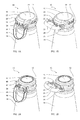
- Fig. 1 is a perspective view of the closure according to the present invention.
- Fig. 2 is a cut out perspective view of the closure according to the present invention.
- Fig. 3 is illustrating the principle of the cam lock according to the present invention.
- Fig. 4 is illustrating the manufacturing of a closure according to the present invention.
- Fig. 5 is illustrating the capping of a beverage bottle according to the present invention.
Detailed description of the drawings
-
Fig. 1A shows a first embodiment of a closure 10 being fastened to a beverage bottle according to the present invention. The closure is fastened onto an outwardly oriented bulge 12 of a bottle neck 14. The bulge 12 surrounds an opening (presently not shown but designated the reference numeral 32 in fig 2A) of the beverage bottle. The bottle neck 14 forms part of a beverage bottle for carbonated beverage, in particular a beer bottle. The closure 10, which is made of thin metal sheet having a thickness of about 0.25 mm, comprises a disc 16 for covering the opening of the beverage bottle and a first skirt part 18 extending from the disc 16 and interlocking with the outwardly oriented bulge 12 of the bottle neck 14. The first skirt part is corrugated and bent inwardly at the "saddle" established in the transition between the outwardly oriented bulge 12 and the bottle neck 14 in order to define a partial periphery being smaller than the outermost periphery of the bulge 12. The closure 10 further comprises a second skirt part 20 and a third skirt part 22 extending from the opposing sides of the first skirt part 18. The second skirt part 20 and the third skirt part 22 define part peripheries being larger than the first part periphery 18 and larger than the periphery of the outwardly oriented bulge 12 of the bottle neck 14 and thereby do not contribute to the fastening of the closure 10 onto the bulge 12. The closure 10 further comprises a fourth skirt part 24 being corrugated and interconnecting the second skirt part 20 and the third skirt part 22 and defining a part periphery being larger than the periphery of the outwardly oriented bulge 12. The fourth skirt part 24 and the outwardly oriented bulge 12 define a spacing between themselves and the fourth skirt part 24 thereby does not contribute to the fastening of the closure 10. The closure 10 further comprises an extension part 26 interconnecting the disc 16, the second skirt 20, the third skirt part 22 and the fourth skirt part 24. The second skirt part 20 and the third skirt part 22 are typically non-corrugated but define opposing bearings 28 28', each bearing 28 28' being constituted by a cavity. The closure 10 further comprises a handle 30. The handle 30 is located in a first position along the bottle neck 14 defining a closed state.
-
Fig. 1B shows a first embodiment of a closure 10 being fastened to a beverage bottle according to the present invention. The handle 30 has been lifted to a second position defining an open state which will be discussed in more detail below.
-
Fig. 2A shows a cut out perspective view of the closure according to the present invention, similar to fig 1A except that the disc, the extension part and the first, second, third and fourth skirt have been removed for revealing a journaling axis comprising a cam axle 34. The cam axle 34 is rotatably held by the opposing bearings of the second and third skirts. The handle 30 is fixedly connected to the cam axle 34 and is presently in the closed state. By rotating the handle 30, the cam axle 34 is rotated as well. The cam axle comprises a first cam surface (not visible here but designated the reference numeral 40 in fig 2B) which is in the present closed state is facing the saddle between the bulge 12 and the bottle neck 14 and therefore not visible. The first cam surface is rounded and defines a first distance from the journaling axis and a part periphery being smaller than the periphery of the bulge 12 in order to fit in the "saddle" between the bulge 12 and the bottle neck 14 and thereby interlock with the bulge 12. The cam axle 34 further comprises a second cam surface 40 which is flat and defines a second distance from the journaling axis, which is smaller than the first distance of the first cam surface, and a part periphery which is equal to or larger than the periphery of the bulge 12. The cam axle 34 comprises slots 36, which allow the cam axle to rotate while assuming a curvature corresponding to the curvature of the outwardly oriented bulge 12 of the beverage battle. When the closure 10 is in the present closed state the slots 36 are open at the second cam surface 40 in order to assume a larger curvature but closed at the first cam surface (not visible) in order to assume a smaller curvature.
-
Fig. 2A shows a cut out perspective view of the closure according to the present invention, similar to fig 1B except that the disc, the extension part and the first, second, third and fourth skirt has been removed for revealing a journaling axis comprising a cam axle 34. The handle 30 has now been rotated to the open state, thereby rotating the cam axle 34 so that the first surface 40 is facing outwardly and the second surface (not visible) is facing inwardly.. The second cam surface has a flat shape and the second distance of the second cam surface is smaller than the first distance of the first cam surface 38 in order to assume an equal or larger part periphery compared to the periphery of the bulge 12 so that the cam axle may slip past the bulge 12. When the closure 10 is in the present open state, the slots 36 are open at the first cam surface 38 in order to assume a larger curvature, but closed at the second cam surface (not visible) in order to assume a smaller curvature.
-
Fig. 3A shows a second embodiment of the closure 10' having a handle 30' being flush with the disc 16' in the closed state. The first cam surface 38' of the cam axle 34' is interlocking with the bulge 12 at the transition between the bulge 12 and the bottle neck 14. The handle 30' has an L-shape. The skirt 18' interlocks with the bulge 12 opposite the cam axle 34'.
-
Fig. 3B shows the second embodiment of the closure 10' having a handle 30' which has been listed above the disc 16' in the open state, thereby rotating the cam axle 34' causing the first cam surface 38' to be oriented away from the bulge 12 and the second cam surface 40' to be facing the bulge 12. The second cam surface 40' defines a smaller radius relative to the journaling axis 34' than the first cam surface 38' and thus allows the cam axle 34' to slip past the second cam surface 40'
-
Fig. 3C shows an optional two step opening of the closure 10' by providing a third cam surface 42 of the cam axle 34'. In this way the closure 10', upon operating the handle 30' into the open state, will not open completely but remain in a degassing state in which the second cam surface 40' has passed the bulge 12, but the third cam surface 42 is interlocking with the bulge 12.
-
Fig. 3D shows an optional two step opening of the closure 10' by providing the third cam surface 42. The closure 10' is completely removed by operating the handle slightly towards the closed state thereby disengaging the third cam surface 42 and the bulge 12.
-
It is understood that the orientation of the handle and the provision of a third cam surface are independent features and it is contemplated that the first embodiment may have a third cam surface as well as the second embodiment may have only a first and a second cam surface.
-
Fig. 4A-E shows the manufacture of the closure 10 involving a multistage progression sheet forming including the illustrated stages 10A-10E.
-
Fig. 4F shows the assembly of the handle 30 onto the closure 10F in which the cam axle 34 is pushed into the bearings 28 28'. The first skirt part 18 and the fourth skirt part 24 are bent in an outward direction in order for the first skirt part 18 to be able to pass the bulge 12 of the bottle neck 14.
-
Figs. 4G and 5A show the finished closure 10 before being applied onto the bulge 12 of the bottle neck 14.
-
Fig. 5B shows the closure 10 above the bulge 12 of the bottle neck 14. The closure is applied having the handle 30 in the first position, i.e. the closed position, in which the first cam surface 38 is facing inwardly and the second cam surface 40 is facing outwardly. To apply the closure 10, a tool 44 has a cavity 46 corresponding to the applied closure 10. When the tool is pressed onto the closure 10 and against the bulge 12 of the bottle neck 14, the outwardly bent first skirt part 18 and the first cam surface together define a periphery being larger than the periphery of the bulge 12 and thereby, both the outwardly bent first skirt part 18 and the first cam surface slip past the bulge 10. Subsequently, the first skirt part 18 and the fourth skirt part 24 are pressed inwardly by the cavity 46 of the tool 44, causing the first skirt part 18 and the first cam surface 38 to interlock with the bulge 12.
-
Fig. 5C shows the closure 10 in the closed state when it is applied onto the bulge 12.
-
Although the present invention has been described above with reference to specific embodiments, it is contemplated that various modifications may be deduced by a person having ordinary skill in the art.
List of parts:
-
- 10.
- Closure
- 12.
- Bulge
- 14.
- Bottle neck
- 16.
- Disc
- 18.
- First skirt part
- 20.
- Second skirt part
- 22.
- Third skirt part
- 24.
- Fourth skirt part
- 26.
- Extension part
- 28.
- Bearing
- 30.
- Handle / Lever
- 32.
- Opening
- 34.
- Journaling axis / Cam axle
- 36.
- Slots
- 38.
- First cam surface /
- 40.
- Second cam surface
- 42.
- Third cam surface
- 44.
- Tool
- 46.
- Cavity