EP2591977B1 - Vehicle steering system and material handling vehicle - Google Patents
Vehicle steering system and material handling vehicle Download PDFInfo
- Publication number
- EP2591977B1 EP2591977B1 EP12191177.0A EP12191177A EP2591977B1 EP 2591977 B1 EP2591977 B1 EP 2591977B1 EP 12191177 A EP12191177 A EP 12191177A EP 2591977 B1 EP2591977 B1 EP 2591977B1
- Authority
- EP
- European Patent Office
- Prior art keywords
- steering
- reaction force
- vehicle
- angle
- control unit
- Prior art date
- Legal status (The legal status is an assumption and is not a legal conclusion. Google has not performed a legal analysis and makes no representation as to the accuracy of the status listed.)
- Active
Links
- 239000000463 material Substances 0.000 title claims description 8
- 230000007246 mechanism Effects 0.000 claims description 6
- 230000008859 change Effects 0.000 claims description 5
- 238000000034 method Methods 0.000 description 9
- 230000010354 integration Effects 0.000 description 6
- 230000008569 process Effects 0.000 description 5
- 230000002123 temporal effect Effects 0.000 description 4
- 230000007935 neutral effect Effects 0.000 description 3
- 230000004044 response Effects 0.000 description 3
- 230000003111 delayed effect Effects 0.000 description 2
- 238000010586 diagram Methods 0.000 description 2
- 230000002441 reversible effect Effects 0.000 description 2
- 239000012530 fluid Substances 0.000 description 1
- 230000005389 magnetism Effects 0.000 description 1
- 230000004048 modification Effects 0.000 description 1
- 238000012986 modification Methods 0.000 description 1
Images


Classifications
-
- B—PERFORMING OPERATIONS; TRANSPORTING
- B62—LAND VEHICLES FOR TRAVELLING OTHERWISE THAN ON RAILS
- B62D—MOTOR VEHICLES; TRAILERS
- B62D6/00—Arrangements for automatically controlling steering depending on driving conditions sensed and responded to, e.g. control circuits
- B62D6/008—Control of feed-back to the steering input member, e.g. simulating road feel in steer-by-wire applications
-
- B—PERFORMING OPERATIONS; TRANSPORTING
- B62—LAND VEHICLES FOR TRAVELLING OTHERWISE THAN ON RAILS
- B62D—MOTOR VEHICLES; TRAILERS
- B62D15/00—Steering not otherwise provided for
- B62D15/02—Steering position indicators ; Steering position determination; Steering aids
- B62D15/025—Active steering aids, e.g. helping the driver by actively influencing the steering system after environment evaluation
-
- B—PERFORMING OPERATIONS; TRANSPORTING
- B62—LAND VEHICLES FOR TRAVELLING OTHERWISE THAN ON RAILS
- B62D—MOTOR VEHICLES; TRAILERS
- B62D5/00—Power-assisted or power-driven steering
- B62D5/001—Mechanical components or aspects of steer-by-wire systems, not otherwise provided for in this maingroup
- B62D5/005—Mechanical components or aspects of steer-by-wire systems, not otherwise provided for in this maingroup means for generating torque on steering wheel or input member, e.g. feedback
- B62D5/006—Mechanical components or aspects of steer-by-wire systems, not otherwise provided for in this maingroup means for generating torque on steering wheel or input member, e.g. feedback power actuated
Definitions
- the invention relates to a vehicle steering system that is used in a material handling vehicle such as a forklift.
- Rear wheels of a forklift are used as steered wheels.
- a steering operation specific to the forklift is performed, that is, first, the front (fork portion) of the forklift is slightly turned in a turning direction by operating a steering member by a small steering angle and then the rear of the forklift is caused to swing out toward the outer side of the corner through a quick steering operation.
- a hydraulic power steering system or an electric power steering system is used as a steering system of a forklift.
- a hydraulic pump is driven by an electric motor to supply hydraulic fluid to a hydraulic cylinder and a piston of the hydraulic cylinder is thereby moved to turn the steered wheels.
- a rack shaft for the rear wheels and tie rods coupled to the rack shaft are moved by driving an electric motor to turn the steered wheels.
- the forklift employs a so-called steer-by-wire power steering system in which a steering member and the rear wheels are not mechanically connected to each other.
- reaction force that should be returned from the rear wheels to the steering member is created on the basis of a steering angle.
- Japanese Patent Application Publication No. 2006-298275 JP 2006-298275 A ) describes a steering control device that controls steering reaction force.
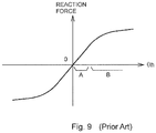
- FIG. 9 shows the conventionally employed correlation between a reaction force of a forklift and a steering angle ⁇ h.
- the abscissa axis represents the steering angle ⁇ h, and the ordinate axis represents the reaction force.
- the flow of a steering operation at the time of making a right turn at a right-angle corner is as follows.
- the steering angle range of the forklift is wide and a steering operation is frequently performed in the forklift, due to the nature of its use. Therefore, the operator needs to operate the steering member by a large amount, so a large burden is placed on the operator. Therefore, there is a need for control for smoothly returning the steering member when the operator reverses the steering direction through a rapid steering operation in the second-half of the turn in the above description (3).
- Document DE 10 2009 050776 A1 discloses a vehicle steering system, comprising: a steered wheel driving mechanism that steers a tire; a steering angle detecting unit that detects a steering angle of a steering member; a reaction force actuator that applies steering reaction force to the steering member; an assist actuator that drives the steered wheel driving mechanism; a yaw rate detecting unit; and a reaction force actuator control unit that sets the steering reaction force as a function of the steering angle detected by the steering angle detecting unit, and that controls the reaction force actuator such that the reaction force actuator generates the set steering reaction force.
- the invention provides a vehicle steering system and material handling vehicle which make it possible to reduce a burden on an operator in performing a steering operation when a vehicle makes a turn, particularly, when a returning operation of a steering member is performed.
- a turning angle of a vehicle body is computed on the basis of a change in a yaw angle of the vehicle body, and, when the computed turning angle is larger than or equal to a reference angle, a steering reaction force that is applied to the steering member is increased.
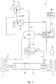
- FIG. 1 is a schematic side view that shows the schematic configuration of a forklift 1 that serves as a material handling vehicle according to the invention.
- the forklift 1 includes a vehicle body 2, a material handling device 3, front wheels 5, rear wheels 6, and a vehicle steering system 7.
- the material handling device 3 is provided at the front of the vehicle body 2.
- the front wheels 5 are drive wheels.
- the rear wheels 6 are steered wheels.
- the front wheels 5 and the rear wheels 6 support the vehicle body 2.
- the vehicle steering system 7 is used to steer the rear wheels 6.
- the vehicle steering system 7 is a so-called steer-by-wire power steering system in which a steering member 10 provided in an operator cab 8 is not mechanically coupled to the rear wheels 6 that serve as the steered wheels.
- the steering member 10 is a hand-turned steering wheel with a knob 10a. The operator grasps the knob 10a rotatably provided on the steering wheel, and operates the steering wheel.
- the forklift 1 further includes a weight sensor that detects the weight of a load.
- the weight sensor includes a hydraulic sensor 23 and a load cell 24.
- the hydraulic sensor 23 measures the hydraulic pressure in a lift cylinder (not shown), which changes with the magnitude of a loaded weight.
- the load cell 24 serves as moment measuring means.
- the load cell 24 is installed at a position on the back side of a fork 25 on which a cargo is loaded so as to measure a force (moment) that the base of the fork 25 pushes the material handling device 3.
- FIG. 2 is a view that shows the overall configuration of the vehicle steering system 7.
- the vehicle steering system 7 includes a shaft 11, a cylindrical column 12, a steering angle sensor 13, a steering torque sensor 14, a reaction force motor 15 and a reaction force system ECU 16.
- the steering member 10 is coupled to the shaft 11.
- the shaft 11 is rotatably supported by the column 12.
- the steering angle sensor 13 detects a steering angle ⁇ h of the steering member 10.
- the steering torque sensor 14 is arranged inside the column 12, and detects a steering torque of the steering member 10.
- the reaction force motor 15 functions as a reaction force actuator that applies steering reaction force to the steering member 10 via a rack shaft 17.
- the ECU 16 executes drive control of the reaction force motor 15.
- the steering torque sensor 14 detects a steering torque by detecting a torsion angle of a torsion bar interposed at the middle of the shaft 11.
- the steering angle sensor 13 detects the rotation angle of the shaft 11 by detecting a change in magnetism resulting from the rotation of the shaft 11 with the use of a magnetic element, such as a Hall sensor, which is attached to the outer periphery of the shaft 11 of the steering member 10.
- the steering angle sensor 13 detects a rotation angle in each of the forward and reverse directions of the steering member 10 from its neutral position.
- the steering angle sensor 13 outputs a rotation angle in the clockwise direction from the neutral position as a positive value, and outputs a rotation angle in the counterclockwise direction from the neutral position as a negative value.
- the reaction force motor 15 is a direct-current motor that is arranged on an axis different from the axis of the shaft 11 in the column 12, and that rotates the shaft 11 at a predetermined gear ratio determined by the rack shaft 17. Note that the reaction force motor 15 may be arranged coaxially with the column 12.
- the vehicle steering system 7 includes the rack shaft 17, a rack support member 18, an assist motor 19, an assist system ECU 22 and a steered angle sensor 20.
- the vehicle steering system 7 is mounted in the vehicle body 2.
- the rack shaft 17 is a steered shaft that extends in the lateral direction of the vehicle.
- the rack shaft 17 is movably supported by the rack support member 18.
- the assist motor 19 moves the rack shaft 17.
- the assist system ECU 22 executes drive control of the assist motor 19.
- the steered angle sensor 20 detects a steered position (referred to as "steered angle" in the specification) of the rear wheels 6.
- the assist motor 19 is a direct-current motor that is coaxial with the rack shaft 17 and that is incorporated in the rack support member 18.
- the rotational motion of the assist motor 19 is converted into a linear motion of the rack shaft 17 inside the rack support member 18.
- the linear motion is transmitted to the rear wheels 6 via tie rods 21R, 21L respectively coupled to a pair of end portions of the rack shaft 17. In this way, the rear wheels 6 are steered.
- the steered angle sensor 20 detects the displaced position of the rack shaft 17 with the use of a stroke sensor on the basis of the fact that the displaced position of the rack shaft 17 corresponds to the steered angle of the rear wheels 6. In this way, the steered angle of the rear wheels 6 is detected.
- the reaction force system ECU 16 and the assist system ECU 22 are connected to each other via an in-vehicle LAN (for example, CAN).
- the vehicle steering system 7 includes a yaw rate sensor 33 and the above-described weight sensor 34.
- the yaw rate sensor 33 is attached to the vehicle body 2.
- the yaw rate sensor 33 is a sensor that detects the turning angular velocity (yaw rate) ⁇ of the vehicle, and detects the turning angular velocity of the vehicle.
- the yaw rate is output as a positive value when the turning angle of the vehicle increases to the right, and is output as a negative value when the turning angle of the vehicle increases to the left.
- the weight sensor 34 is a sensor that detects the weight of a load loaded on the fork 25, as described above.
- a wheel speed sensor 35 is attached to the vehicle body 2.
- the wheel speed sensor 35 detects the rotation speed of one of the front wheels 5 or one of the rear wheels 6.
- the wheel speed sensor 35 is a sensor that optically reads the rotation speed of the wheel, and multiplies the read rotation speed by the effective rotation radius of a corresponding tire. In this way, a vehicle speed v is detected.
- the assist system ECU 22 rotates the assist motor 19 on the basis of the steering angle detected by the steering angle sensor 13.
- the rotation of the assist motor 19 is converted to a parallel motion of the rack shaft 17.
- the parallel motion is transmitted to the rear wheels 6 via the tie rods 21R, 21L coupled to the respective end portions of the rack shaft 17. In this way, the rear wheels 6 are steered.
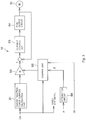
- FIG. 3 shows a control block diagram for reaction force control that is executed by the reaction force system ECU 16.
- a steering angle signal which indicates the detected steering angle ⁇ h, is input from the steering angle sensor 13 into a target reaction force current calculation unit B1 of the reaction force system ECU 16 via the in-vehicle LAN.
- the target reaction force current calculation unit B1 stores the correlation between the steering angle ⁇ h and the reaction force, shown in FIG. 9 , as a function, and converts the steering angle ⁇ h into a target reaction force current on the basis of the correlation.
- the target reaction force current is amplified by an amplifier B2 having a gain K, and is input into a current control unit B3. Meanwhile, a current that flows through the reaction force motor 15 is detected, and an inverted signal of the current is input into the current control unit B3. Then, a difference between the target reaction force current and the current that flows through the reaction force motor 15 is calculated in the current control unit B3. The difference is supplied to a PWM output circuit B4, and a PWM drive signal for driving the reaction force motor 15 is generated. Then, by supplying the PWM drive signal to the reaction force motor 15, reaction torque is applied to the steering member 10 via the rack shaft 17 and the shaft 11.
- a control unit B5 that changes the gain K of the amplifier B2 is provided.
- a signal that indicates the steering angle ⁇ h, a signal that indicates the yaw angle (turning angle) ⁇ of the vehicle body 2 from an integration circuit B6 and a signal that indicates the weight W of the load are input into the control unit B5.
- the integration circuit B6 is a computing unit that subjects the yaw rate ⁇ , which is obtained from the yaw rate sensor 33, to temporal integration according to Equation 1 indicated below, to calculate the yaw angle ⁇ of the vehicle body 2.
- ⁇ ⁇ ⁇ dt
- an integral range is from time when the vehicle is travelling straight ahead before a turn, to current time during the turn.
- a start of the turn is detected on the basis of the fact that the steering angle ⁇ h detected by the steering angle sensor 13 exceeds a certain threshold.
- the gain K of the amplifier B2 is controlled by the control unit B5 so as to be increased over a predetermined period of time.
- the gain K of the amplifier B2 is set to "1" at first (step S1), and a yaw angle ⁇ obtained from the integration circuit B6 is acquired (step S2). Subsequently, the absolute value of the yaw angle ⁇ is compared with a reference value S1 (step S3).
- the reference value S1 is set to a value (for example, 80 degrees) based on which it is possible to determine that the vehicle is turning a corner having a large angle, such as a right-angle corner.
- step S3 When it is determined in step S3 that the absolute value of the yaw angle ⁇ is smaller than the reference value S1, reaction control is executed on the basis of the default gain K (step S11).
- the process proceeds to step S4, and the gain K of the amplifier B2 is increased.
- the gain K is set to "1.5".
- a timer is started at the same time that the gain K of the amplifier B2 is increased (step S5), and reaction force control is executed on the basis of the increased gain K (step S6).
- the reaction force control is executed until the steering angle ⁇ h falls within a predetermined range (- ⁇ 0 ⁇ ⁇ h ⁇ ⁇ 0) (step S7).
- the value ⁇ 0 for determining the range is a threshold for determining whether the vehicle has returned to straight ahead travelling. Therefore, the value ⁇ 0 is set to a small value (for example, 5 degrees).
- the integration circuit B6 clears the yaw angle ⁇ , that is, the temporal integral value of the yaw rate ⁇ , to 0 (step S9), and the count value of the timer is returned to 0 (step S10).
- the control unit B5 periodically and repeatedly executes the reaction force control.
- the process starts from step S1 again.
- the process proceeds from step S7 to step S8, and it is determined whether the count value of the timer has reached a set value T1.
- reaction force control is continued (step S6).
- reaction force control is aborted (YES in step S8).
- the set value T1 is set to a value (for example, 1 second) which is determined to be usually required to return the steering wheel while the vehicle is turning at a right-angle corner.
- a value for example, 1 second
- the set value T1 is set to a value (for example, 1 second) which is determined to be usually required to return the steering wheel while the vehicle is turning at a right-angle corner.
- the operator of the forklift 1 rotates the steering member 10 while the vehicle is travelling, and is able to steer the forklift 1 while feeling a certain steering reaction force. Particularly, at a right-angle corner, by increasing a steering reaction force in the second-half of a turn, it is possible to quickly cause the vehicle to be directed straight ahead.
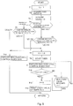
- FIG. 5 is a flowchart for illustrating a reaction force control procedure set by taking into account a loaded weight.
- the weight W of a load which is detected by the weight sensor 34, is used.
- the gain K of the amplifier B2 is set to "1" at first (step T1), and the yaw angle ⁇ obtained from the integration circuit B6 and the weight W of the load are acquired (step T2).
- step T4 On the basis of a signal of a shift gear, which indicates whether the forklift 1 is travelling forward or backing up, it is determined whether the forklift 1 is travelling forward or backing up (step T4).
- the absolute value of the yaw angle ⁇ is compared with the reference value S1 (step T5).
- the reference value S1 is set to a value based on which it is possible to determine that the vehicle is turning a corner having a large angle, such as a right-angle corner.
- the set value of the reference value S1 is changed on the basis of the weight W of the load.
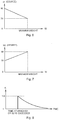
- FIG. 6 is a graph that shows the correlation between the weight W of a load and the reference value S1.
- the reference value S1 is set to, for example, 80 degrees.
- the reference value S1 is reduced.
- the reference value S1 is set to, for example, 70 degrees.
- the reason why the reference value S 1 is reduced as the weight W of the load increases is as follows. Because the vehicle is likely to oversteer when a loaded weight is large, the function of returning the steering wheel needs to be carried out from a relatively early stage of a turn.
- the absolute value of the yaw angle ⁇ is compared with a reference value S2 (step T6).
- the reference value S2 is set to, for example, 80 degrees. This is because, when the vehicle turns while backing up, tires on the front side in the traveling direction, that is, the rear wheels, serve as the steered wheels. Therefore, the vehicle is likely to understeer when the loaded weight is large. Therefore, the timing at which reaction force is given to the operator is delayed and the steering member is returned at a relatively last stage of the turn.
- step T5 When it is determined in step T5 that the absolute value of the yaw angle ⁇ is smaller than or equal to the reference value S1 or when it is determined in step T6 that the absolute value of the yaw angle ⁇ is smaller than or equal to the reference value S2, reaction force control based on the normal gain K is executed (step T14).
- step T5 When it is determined in step T5 that the absolute value of the yaw angle ⁇ is larger than the reference value S1 or when it is determined in step T6 that the absolute value of the yaw angle ⁇ is larger than the reference value S2, the process proceeds to step T7, and the gain K of the amplifier B2 is increased.
- the gain K is set to, for example, "1.5".
- step T8 to step T13 is similar to that described with reference to FIG. 4 .
- the timing at which a steering reaction force is increased is advanced by a larger amount as the weight W of the load increases; whereas, when the vehicle is turning while backing up, the timing at which a steering reaction force is increased is retarded by a larger amount as the weight W of the load increases.
- FIG. 8 is a graph that shows a change in the gain K in this case.
- the vehicle steering system 7 includes the yaw rate sensor 33 and the yaw angle of the vehicle is calculated by integrating the vehicle yaw rate ⁇ .
- the yaw rate sensor 33 may be omitted and the yaw angle of the vehicle may be calculated by integrating the steering angle detected by the steering angle sensor 13.
- the rack shaft 17 that is driven by the assist motor 19 is employed as a steered wheel driving mechanism.
- a hydraulic cylinder that is driven by an electric hydraulic pump may be employed. Further, various modifications may be made within the scope of the invention.
Landscapes
- Engineering & Computer Science (AREA)
- Chemical & Material Sciences (AREA)
- Combustion & Propulsion (AREA)
- Transportation (AREA)
- Mechanical Engineering (AREA)
- Steering Control In Accordance With Driving Conditions (AREA)
- Power Steering Mechanism (AREA)
Description
- The invention relates to a vehicle steering system that is used in a material handling vehicle such as a forklift. 2. Discussion of Background
- Rear wheels of a forklift are used as steered wheels. When the forklift turns a corner, a steering operation specific to the forklift is performed, that is, first, the front (fork portion) of the forklift is slightly turned in a turning direction by operating a steering member by a small steering angle and then the rear of the forklift is caused to swing out toward the outer side of the corner through a quick steering operation.
- A hydraulic power steering system or an electric power steering system is used as a steering system of a forklift. With the hydraulic power steering system, in response to an operator's steering operation, a hydraulic pump is driven by an electric motor to supply hydraulic fluid to a hydraulic cylinder and a piston of the hydraulic cylinder is thereby moved to turn the steered wheels. With the electric power steering system, in response to an operator's steering operation, a rack shaft for the rear wheels and tie rods coupled to the rack shaft are moved by driving an electric motor to turn the steered wheels.
- The forklift employs a so-called steer-by-wire power steering system in which a steering member and the rear wheels are not mechanically connected to each other. In this case, in order to give the operator a feel of reaction force, reaction force that should be returned from the rear wheels to the steering member is created on the basis of a steering angle. Japanese Patent Application Publication No.
2006-298275 JP 2006-298275 A -
FIG. 9 shows the conventionally employed correlation between a reaction force of a forklift and a steering angle θh. The abscissa axis represents the steering angle θh, and the ordinate axis represents the reaction force. Under this correlation, the flow of a steering operation at the time of making a right turn at a right-angle corner is as follows. - (1) At an initial stage (around 0 degrees) of the turn, the front (fork portion) is directed slightly to the right by operating the steering member by a small steering angle. At this time, the steering angle θh is within a range indicated by "A" in
FIG. 9 , and the reaction force received by the operator is small. - (2) In the first-half of the turn, the rear of the forklift is caused to swing out toward the outer side of the corner through a quick steering operation. At this time, the steering angle θh is within a range indicated by "B" in
FIG. 9 , and the operator receives a large reaction force. The reaction force is given to the operator in order to prevent an unintentional increase in the steering angle due to an excessive force in steering operation. The operator rotates the steering member against the reaction force. - (3) In the second-half of the turn, the steering direction should be reversed to cause the rear of the forklift to be directed straight ahead through a rapid steering operation. If the return of the steering member is delayed, it is difficult to cause the forklift to be directed straight ahead. For example, the forklift excessively turns beyond a right angle, which may lead to, for example, an accidental contact.
- The steering angle range of the forklift is wide and a steering operation is frequently performed in the forklift, due to the nature of its use. Therefore, the operator needs to operate the steering member by a large amount, so a large burden is placed on the operator. Therefore, there is a need for control for smoothly returning the steering member when the operator reverses the steering direction through a rapid steering operation in the second-half of the turn in the above description (3).
-
Document DE 10 2009 050776 A1 discloses a vehicle steering system, comprising: a steered wheel driving mechanism that steers a tire; a steering angle detecting unit that detects a steering angle of a steering member; a reaction force actuator that applies steering reaction force to the steering member; an assist actuator that drives the steered wheel driving mechanism; a yaw rate detecting unit; and a reaction force actuator control unit that sets the steering reaction force as a function of the steering angle detected by the steering angle detecting unit, and that controls the reaction force actuator such that the reaction force actuator generates the set steering reaction force. - The invention provides a vehicle steering system and material handling vehicle which make it possible to reduce a burden on an operator in performing a steering operation when a vehicle makes a turn, particularly, when a returning operation of a
steering member is performed. - According to a feature of an example of the invention, a turning angle of a vehicle body is computed on the basis of a change in a yaw angle of the vehicle body, and, when the computed turning angle is larger than or equal to a reference angle, a steering reaction force that is applied to the steering member is increased.
- The foregoing and further objects, features and advantages of the invention will become apparent from the following description of example embodiments with reference to the accompanying drawings, wherein like numerals are used to represent like elements and wherein:
-
FIG. 1 is a schematic side view that shows the schematic configuration of a forklift; -
FIG. 2 is a view that shows the overall configuration of a vehicle steering system; -
FIG. 3 is a control block diagram for reaction force control executed by a reaction force system ECU; -
FIG. 4 is a flowchart for illustrating the procedure of reaction force control; -
FIG. 5 is a flowchart for illustrating the procedure of reaction force control that is set by taking into account a loaded weight; -
FIG. 6 is a graph that shows the correlation between the weight of a load and a reference value at the time of forward travelling; -
FIG. 7 is a graph that shows the correlation between the weight of a load and a reference value at the time of reverse travelling; -
FIG. 8 is a graph that shows a temporal change in gain in the case where the gain is set to a fixed value and then the gain is reduced with time; and -
FIG. 9 is a graph that shows the correlation between a steering angle and a reaction force in related art. - Hereinafter, embodiments of the invention will be described with reference to the accompanying drawings.
-
FIG. 1 is a schematic side view that shows the schematic configuration of aforklift 1 that serves as a material handling vehicle according to the invention. Theforklift 1 includes avehicle body 2, amaterial handling device 3,front wheels 5,rear wheels 6, and avehicle steering system 7. Thematerial handling device 3 is provided at the front of thevehicle body 2. Thefront wheels 5 are drive wheels. Therear wheels 6 are steered wheels. Thefront wheels 5 and therear wheels 6 support thevehicle body 2. Thevehicle steering system 7 is used to steer therear wheels 6. - The
vehicle steering system 7 is a so-called steer-by-wire power steering system in which asteering member 10 provided in anoperator cab 8 is not mechanically coupled to therear wheels 6 that serve as the steered wheels. In the present embodiment, thesteering member 10 is a hand-turned steering wheel with aknob 10a. The operator grasps theknob 10a rotatably provided on the steering wheel, and operates the steering wheel. - The
forklift 1 further includes a weight sensor that detects the weight of a load. The weight sensor includes ahydraulic sensor 23 and aload cell 24. Thehydraulic sensor 23 measures the hydraulic pressure in a lift cylinder (not shown), which changes with the magnitude of a loaded weight. Theload cell 24 serves as moment measuring means. Theload cell 24 is installed at a position on the back side of afork 25 on which a cargo is loaded so as to measure a force (moment) that the base of thefork 25 pushes thematerial handling device 3. -
FIG. 2 is a view that shows the overall configuration of thevehicle steering system 7. Thevehicle steering system 7 includes ashaft 11, acylindrical column 12, asteering angle sensor 13, asteering torque sensor 14, areaction force motor 15 and a reactionforce system ECU 16. Thesteering member 10 is coupled to theshaft 11. Theshaft 11 is rotatably supported by thecolumn 12. Thesteering angle sensor 13 detects a steering angle θh of thesteering member 10. Thesteering torque sensor 14 is arranged inside thecolumn 12, and detects a steering torque of the steeringmember 10. Thereaction force motor 15 functions as a reaction force actuator that applies steering reaction force to the steeringmember 10 via arack shaft 17. TheECU 16 executes drive control of thereaction force motor 15. - The
steering torque sensor 14 detects a steering torque by detecting a torsion angle of a torsion bar interposed at the middle of theshaft 11. Thesteering angle sensor 13 detects the rotation angle of theshaft 11 by detecting a change in magnetism resulting from the rotation of theshaft 11 with the use of a magnetic element, such as a Hall sensor, which is attached to the outer periphery of theshaft 11 of the steeringmember 10. In the present embodiment, thesteering angle sensor 13 detects a rotation angle in each of the forward and reverse directions of the steeringmember 10 from its neutral position. Thesteering angle sensor 13 outputs a rotation angle in the clockwise direction from the neutral position as a positive value, and outputs a rotation angle in the counterclockwise direction from the neutral position as a negative value. - The
reaction force motor 15 is a direct-current motor that is arranged on an axis different from the axis of theshaft 11 in thecolumn 12, and that rotates theshaft 11 at a predetermined gear ratio determined by therack shaft 17. Note that thereaction force motor 15 may be arranged coaxially with thecolumn 12. - The
vehicle steering system 7 includes therack shaft 17, arack support member 18, anassist motor 19, anassist system ECU 22 and a steeredangle sensor 20. Thevehicle steering system 7 is mounted in thevehicle body 2. Therack shaft 17 is a steered shaft that extends in the lateral direction of the vehicle. Therack shaft 17 is movably supported by therack support member 18. Theassist motor 19 moves therack shaft 17. Theassist system ECU 22 executes drive control of theassist motor 19. The steeredangle sensor 20 detects a steered position (referred to as "steered angle" in the specification) of therear wheels 6. - The
assist motor 19 is a direct-current motor that is coaxial with therack shaft 17 and that is incorporated in therack support member 18. The rotational motion of theassist motor 19 is converted into a linear motion of therack shaft 17 inside therack support member 18. The linear motion is transmitted to therear wheels 6 viatie rods rack shaft 17. In this way, therear wheels 6 are steered. The steeredangle sensor 20 detects the displaced position of therack shaft 17 with the use of a stroke sensor on the basis of the fact that the displaced position of therack shaft 17 corresponds to the steered angle of therear wheels 6. In this way, the steered angle of therear wheels 6 is detected. - In addition, in order to steer the
rear wheels 6 in response to an operation of the steeringmember 10, the reactionforce system ECU 16 and theassist system ECU 22 are connected to each other via an in-vehicle LAN (for example, CAN). Furthermore, thevehicle steering system 7 includes ayaw rate sensor 33 and the above-describedweight sensor 34. Theyaw rate sensor 33 is attached to thevehicle body 2. Theyaw rate sensor 33 is a sensor that detects the turning angular velocity (yaw rate) γ of the vehicle, and detects the turning angular velocity of the vehicle. The yaw rate is output as a positive value when the turning angle of the vehicle increases to the right, and is output as a negative value when the turning angle of the vehicle increases to the left. Theweight sensor 34 is a sensor that detects the weight of a load loaded on thefork 25, as described above. - Furthermore, a
wheel speed sensor 35 is attached to thevehicle body 2. Thewheel speed sensor 35 detects the rotation speed of one of thefront wheels 5 or one of therear wheels 6. Thewheel speed sensor 35 is a sensor that optically reads the rotation speed of the wheel, and multiplies the read rotation speed by the effective rotation radius of a corresponding tire. In this way, a vehicle speed v is detected. - The
assist system ECU 22 rotates theassist motor 19 on the basis of the steering angle detected by thesteering angle sensor 13. The rotation of theassist motor 19 is converted to a parallel motion of therack shaft 17. The parallel motion is transmitted to therear wheels 6 via thetie rods rack shaft 17. In this way, therear wheels 6 are steered. -
FIG. 3 shows a control block diagram for reaction force control that is executed by the reactionforce system ECU 16. A steering angle signal, which indicates the detected steering angle θh, is input from thesteering angle sensor 13 into a target reaction force current calculation unit B1 of the reactionforce system ECU 16 via the in-vehicle LAN. The target reaction force current calculation unit B1 stores the correlation between the steering angle θh and the reaction force, shown inFIG. 9 , as a function, and converts the steering angle θh into a target reaction force current on the basis of the correlation. - The target reaction force current is amplified by an amplifier B2 having a gain K, and is input into a current control unit B3. Meanwhile, a current that flows through the
reaction force motor 15 is detected, and an inverted signal of the current is input into the current control unit B3. Then, a difference between the target reaction force current and the current that flows through thereaction force motor 15 is calculated in the current control unit B3. The difference is supplied to a PWM output circuit B4, and a PWM drive signal for driving thereaction force motor 15 is generated. Then, by supplying the PWM drive signal to thereaction force motor 15, reaction torque is applied to the steeringmember 10 via therack shaft 17 and theshaft 11. - A control unit B5 that changes the gain K of the amplifier B2 is provided. A signal that indicates the steering angle θh, a signal that indicates the yaw angle (turning angle) δ of the
vehicle body 2 from an integration circuit B6 and a signal that indicates the weight W of the load are input into the control unit B5. The integration circuit B6 is a computing unit that subjects the yaw rate γ, which is obtained from theyaw rate sensor 33, to temporal integration according toEquation 1 indicated below, to calculate the yaw angle δ of thevehicle body 2.
steering angle sensor 13 exceeds a certain threshold. When the turning angle of thevehicle body 2 is larger than or equal to a reference angle, the gain K of the amplifier B2 is controlled by the control unit B5 so as to be increased over a predetermined period of time. - Hereinafter, a control process executed by the control unit B5 will be described in detail with reference to the flowchart in
FIG. 4 . Note that the weight W of a load is used in another flowchart inFIG. 5 that shows a reaction force control procedure that is set by taking into account a loaded weight, and is not taken into account when the flowchart inFIG. 4 is executed. - As shown in
FIG. 4 , the gain K of the amplifier B2 is set to "1" at first (step S1), and a yaw angle δ obtained from the integration circuit B6 is acquired (step S2). Subsequently, the absolute value of the yaw angle δ is compared with a reference value S1 (step S3). The reference value S1 is set to a value (for example, 80 degrees) based on which it is possible to determine that the vehicle is turning a corner having a large angle, such as a right-angle corner. - When it is determined in step S3 that the absolute value of the yaw angle δ is smaller than the reference value S1, reaction control is executed on the basis of the default gain K (step S11). When the absolute value of the yaw angle δ is larger than the reference value S1, the process proceeds to step S4, and the gain K of the amplifier B2 is increased. For example, the gain K is set to "1.5". By increasing the steering reaction force in the second-half of a turn in this way, it is possible to assist a return operation of the steering member to quickly cause the vehicle to be directed straight ahead.
- A timer is started at the same time that the gain K of the amplifier B2 is increased (step S5), and reaction force control is executed on the basis of the increased gain K (step S6). The reaction force control is executed until the steering angle θh falls within a predetermined range (-θ0 < θh < θ0) (step S7). The value θ0 for determining the range is a threshold for determining whether the vehicle has returned to straight ahead travelling. Therefore, the value θ0 is set to a small value (for example, 5 degrees). When the steering angle θh falls within the predetermined range (-θ0 < θh < θ0), the integration circuit B6 clears the yaw angle δ, that is, the temporal integral value of the yaw rate γ, to 0 (step S9), and the count value of the timer is returned to 0 (step S10).
- The control unit B5 periodically and repeatedly executes the reaction force control. In the next cycle, the process starts from step S1 again. Before the steering angle θh falls within the predetermined range (-θ0 < θh < θ0), the process proceeds from step S7 to step S8, and it is determined whether the count value of the timer has reached a set value T1. Until the count value reaches the set value T1, reaction force control is continued (step S6). When the count value reaches the set value T1, even if the steering angle θh has not fallen within the predetermined range (-θ0 < θh < θ0), reaction force control is aborted (YES in step S8). The set value T1 is set to a value (for example, 1 second) which is determined to be usually required to return the steering wheel while the vehicle is turning at a right-angle corner. When the vehicle is turning at a 180-degree corner instead of turning at a right-angle corner, that is, making a U-turn, returning the steering member requires a period of time that is longer than or equal to the set value T1. Therefore, in this case, after a lapse of the set value T1, assist through reaction force is stopped and the temporal integral value of the yaw rate γ is cleared to 0 (step S9), and the count value of the timer is returned to 0 (step S10). The reason why the set value T1 is provided is as follows. When it takes longer than or equal to the set value T1 to return the steering member, it is determined that the vehicle is making a U-turn and an increase in the reaction force assist is cancelled.
- According to the embodiment of the invention as described above, the operator of the
forklift 1 rotates the steeringmember 10 while the vehicle is travelling, and is able to steer theforklift 1 while feeling a certain steering reaction force. Particularly, at a right-angle corner, by increasing a steering reaction force in the second-half of a turn, it is possible to quickly cause the vehicle to be directed straight ahead. -
FIG. 5 is a flowchart for illustrating a reaction force control procedure set by taking into account a loaded weight. In this control, the weight W of a load, which is detected by theweight sensor 34, is used. The gain K of the amplifier B2 is set to "1" at first (step T1), and the yaw angle δ obtained from the integration circuit B6 and the weight W of the load are acquired (step T2). Subsequently, on the basis of a signal of a shift gear, which indicates whether theforklift 1 is travelling forward or backing up, it is determined whether theforklift 1 is travelling forward or backing up (step T4). When theforklift 1 is travelling forward, the absolute value of the yaw angle δ is compared with the reference value S1 (step T5). The reference value S1 is set to a value based on which it is possible to determine that the vehicle is turning a corner having a large angle, such as a right-angle corner. In this control, the set value of the reference value S1 is changed on the basis of the weight W of the load.FIG. 6 is a graph that shows the correlation between the weight W of a load and the reference value S1. When there is no load (weight W = 0), the reference value S1 is set to, for example, 80 degrees. As the weight W of the load increases, the reference value S1 is reduced. When the weight W of the load is close to a limit weight, the reference value S1 is set to, for example, 70 degrees. The reason why thereference value S 1 is reduced as the weight W of the load increases is as follows. Because the vehicle is likely to oversteer when a loaded weight is large, the function of returning the steering wheel needs to be carried out from a relatively early stage of a turn. - On the other hand, when the vehicle is backing up, the absolute value of the yaw angle δ is compared with a reference value S2 (step T6). As shown in
FIG. 7 , the reference value S2 is set to, for example, 75 degrees when there is no load (weight W = 0), and the reference value S2 is increased as the weight W of the load increases. When the weight W of the load is close to a limit weight, the reference value S2 is set to, for example, 80 degrees. This is because, when the vehicle turns while backing up, tires on the front side in the traveling direction, that is, the rear wheels, serve as the steered wheels. Therefore, the vehicle is likely to understeer when the loaded weight is large. Therefore, the timing at which reaction force is given to the operator is delayed and the steering member is returned at a relatively last stage of the turn. - When it is determined in step T5 that the absolute value of the yaw angle δ is smaller than or equal to the reference value S1 or when it is determined in step T6 that the absolute value of the yaw angle δ is smaller than or equal to the reference value S2, reaction force control based on the normal gain K is executed (step T14). When it is determined in step T5 that the absolute value of the yaw angle δ is larger than the reference value S1 or when it is determined in step T6 that the absolute value of the yaw angle δ is larger than the reference value S2, the process proceeds to step T7, and the gain K of the amplifier B2 is increased. The gain K is set to, for example, "1.5". By increasing the steering reaction force in the second-half of a turn, in which the absolute value of the yaw angle δ exceeds the reference value S1 or S2, in this way, it is possible to assist a return of the steering member to quickly cause the vehicle to be directed straight ahead. Control after this (step T8 to step T13) is similar to that described with reference to
FIG. 4 . - As described above, when the vehicle is turning while travelling forward, the timing at which a steering reaction force is increased is advanced by a larger amount as the weight W of the load increases; whereas, when the vehicle is turning while backing up, the timing at which a steering reaction force is increased is retarded by a larger amount as the weight W of the load increases. By employing the above control, the operator of the
forklift 1 is able to perform a steering operation at a right-angle corner while receiving a steering assist force at an appropriate timing in the second-half of a turn. Thus, it is possible to quickly cause the vehicle to be directed straight ahead while unstable turn of the vehicle in the second-half of the turn is prevented and a burden placed on the operator in performing a steering operation is reduced. - The embodiment of the invention has been described above. However, the invention is not limited to the above-described embodiment. For example, an embodiment may be employed, in which the gain K of the amplifier B2 is set to a fixed value, that is, K = 1.5, at the time when the yaw angle exceeds a reference value S, and then the gain K is gradually reduced with a lapse of time.
FIG. 8 is a graph that shows a change in the gain K in this case. By gradually reducing the gain K in this way, a reaction force is gradually reduced until returning of the steering wheel progresses and the vehicle is caused to travel straight ahead. In this way, an unstable state at the time when the vehicle turns is avoided, and it is possible to make the operator feel a natural steering feel. - In addition, in the above-described embodiment, the
vehicle steering system 7 includes theyaw rate sensor 33 and the yaw angle of the vehicle is calculated by integrating the vehicle yaw rate γ. Alternatively, theyaw rate sensor 33 may be omitted and the yaw angle of the vehicle may be calculated by integrating the steering angle detected by thesteering angle sensor 13. In addition, instead of the configuration in which therear wheels 6 are respectively provided at the right and left sides of thevehicle body 2 as the steered wheels, a configuration in which a singlerear wheel 6 is provided at the center in the lateral direction of thevehicle body 2 may be employed. In addition, in the above-described embodiment, therack shaft 17 that is driven by theassist motor 19 is employed as a steered wheel driving mechanism. Alternatively, a hydraulic cylinder that is driven by an electric hydraulic pump may be employed. Further, various modifications may be made within the scope of the invention.
Claims (8)
- A vehicle steering system, comprising:a steered wheel driving mechanism that steers a tire (6);a steering angle detecting unit (13) that detects a steering angle (θh) of a steering member (10);a reaction force actuator (15) that applies steering reaction force to the steering member (10);an assist actuator (19) that drives the steered wheel driving mechanism;a yaw angle detecting unit (33) that detects a yaw angle (δ) of a vehicle body (2) ; anda reaction force actuator control unit (16) that sets the steering reaction force as a function of the steering angle (θh) detected by the steering angle detecting unit (13), and that controls the reaction force actuator (15) such that the reaction force actuator (15) generates the set steering reaction force, whereinthe reaction force actuator control unit (16) computes a turning amount of the vehicle body (2) based on a change in the yaw angle (δ) of the vehicle body (2), which is detected by the yaw angle detecting unit (33), and
when the computed turning amount is larger than or equal to a reference angle (S1), the reaction force actuator control unit (16) increases the steering reaction force that is applied to the steering member (10). - The vehicle steering system according to claim 1, wherein the reaction force actuator control unit (16) reduces the increased steering reaction force with a lapse of time.
- The vehicle steering system according to claim 1 or 2, wherein the reaction force actuator control unit (16) stops the increase in the steering reaction force when a travelling direction of a vehicle becomes a straight-ahead direction.
- The vehicle steering system according to any one of claims 1 to 3, wherein the reaction force actuator control unit (16) increases the steering reaction force that is applied to the steering member (10) over a predetermined period of time.
- The vehicle steering system according to any one of claims 1 to 4, further comprising a weight detecting unit (34) that detects a weight of a load, wherein the reaction force actuator control unit (16) changes a value of the reference angle (S1, S2) based on a value detected by the weight detecting unit (34).
- The vehicle steering system according to claim 5, wherein the reaction force actuator control unit (16) reduces the value of the reference angle (S1) as the value detected by the weight detecting unit (34) is larger while a vehicle is travelling forward, and increases the value of the reference angle (S2) as the value detected by the weight detecting unit (34) is larger while the vehicle is backing up.
- The vehicle steering system according to any one of claims 1 to 6, wherein a steer-by-wire system in which the steering member (10) is not mechanically coupled to the steered wheel driving mechanism is employed.
- A material handling vehicle comprising the vehicle steering system according to any one of claims 1 to 7.
Applications Claiming Priority (1)
| Application Number | Priority Date | Filing Date | Title |
|---|---|---|---|
| JP2011244629A JP5800194B2 (en) | 2011-11-08 | 2011-11-08 | Vehicle steering system and cargo handling vehicle |
Publications (3)
| Publication Number | Publication Date |
|---|---|
| EP2591977A2 EP2591977A2 (en) | 2013-05-15 |
| EP2591977A3 EP2591977A3 (en) | 2014-08-20 |
| EP2591977B1 true EP2591977B1 (en) | 2017-02-01 |
Family
ID=47143677
Family Applications (1)
| Application Number | Title | Priority Date | Filing Date |
|---|---|---|---|
| EP12191177.0A Active EP2591977B1 (en) | 2011-11-08 | 2012-11-03 | Vehicle steering system and material handling vehicle |
Country Status (4)
| Country | Link |
|---|---|
| US (1) | US8855859B2 (en) |
| EP (1) | EP2591977B1 (en) |
| JP (1) | JP5800194B2 (en) |
| CN (1) | CN103085859B (en) |
Families Citing this family (8)
| Publication number | Priority date | Publication date | Assignee | Title |
|---|---|---|---|---|
| US9302893B2 (en) * | 2013-02-07 | 2016-04-05 | The Raymond Corporation | Vibration control systems and methods for industrial lift trucks |
| CN103818260A (en) * | 2014-02-26 | 2014-05-28 | 安徽合力股份有限公司 | Combined meter of diesel fork lift truck based on CAN bus |
| CN204775442U (en) * | 2015-06-24 | 2015-11-18 | 浙江中力机械有限公司 | Electronic steering formula singly drives three fulcrum fork truck |
| US9828026B2 (en) * | 2016-02-02 | 2017-11-28 | Premier Coil Solutions, Inc. | Transport trailer load balancing suspension and steering systems |
| JP6756216B2 (en) * | 2016-09-27 | 2020-09-16 | 株式会社ジェイテクト | Steering control device |
| JP6737202B2 (en) * | 2017-02-16 | 2020-08-05 | 株式会社島津製作所 | forklift |
| CN111497925B (en) * | 2019-01-30 | 2022-05-13 | 比亚迪股份有限公司 | Forklift steering axle and forklift |
| US11685427B2 (en) | 2021-04-12 | 2023-06-27 | Toyota Material Handling, Inc. | Electric actuator steering system for forklifts |
Family Cites Families (17)
| Publication number | Priority date | Publication date | Assignee | Title |
|---|---|---|---|---|
| JPH0686222B2 (en) * | 1988-03-14 | 1994-11-02 | 本田技研工業株式会社 | Steering device |
| JPH10244952A (en) * | 1997-03-04 | 1998-09-14 | Nippon Yusoki Co Ltd | Electric power steering unit |
| JPH115419A (en) * | 1997-06-18 | 1999-01-12 | Toyota Autom Loom Works Ltd | Car body rocking control device for industrial vehicle |
| JP3775978B2 (en) * | 2000-09-26 | 2006-05-17 | 日本輸送機株式会社 | Electric power steering device |
| JP4470565B2 (en) * | 2004-04-09 | 2010-06-02 | 株式会社ジェイテクト | Vehicle steering system |
| WO2006054678A1 (en) * | 2004-11-19 | 2006-05-26 | Mitsubishi Heavy Industries, Ltd. | Overturning prevention device for forklift truck |
| JP2006168483A (en) * | 2004-12-14 | 2006-06-29 | Nissan Motor Co Ltd | Vehicle steering controller |
| JP2006264393A (en) * | 2005-03-22 | 2006-10-05 | Honda Motor Co Ltd | Steering gear for vehicle |
| JP4876433B2 (en) | 2005-04-22 | 2012-02-15 | 日産自動車株式会社 | Vehicle steering control device |
| JP4941723B2 (en) * | 2006-12-28 | 2012-05-30 | 株式会社ジェイテクト | Vehicle steering system |
| JP2008296681A (en) * | 2007-05-30 | 2008-12-11 | Komatsu Ltd | Steering control device for vehicle |
| JP5386103B2 (en) * | 2008-04-17 | 2014-01-15 | ニチユ三菱フォークリフト株式会社 | Vehicle steering control device |
| JP5167086B2 (en) * | 2008-11-18 | 2013-03-21 | 本田技研工業株式会社 | Electric power steering device |
| JP2010254237A (en) * | 2009-04-28 | 2010-11-11 | Jtekt Corp | Steering device for vehicle |
| JP5392550B2 (en) * | 2009-05-13 | 2014-01-22 | 株式会社ジェイテクト | Vehicle steering system |
| DE102009050776B4 (en) * | 2009-10-27 | 2021-06-24 | Audi Ag | Method for applying a torque or a force to a steering handle, as well as a motor vehicle |
| JP5747482B2 (en) * | 2010-03-26 | 2015-07-15 | 日産自動車株式会社 | Vehicle environment recognition device |
-
2011
- 2011-11-08 JP JP2011244629A patent/JP5800194B2/en active Active
-
2012
- 2012-10-18 CN CN201210397297.0A patent/CN103085859B/en active Active
- 2012-10-30 US US13/664,098 patent/US8855859B2/en active Active
- 2012-11-03 EP EP12191177.0A patent/EP2591977B1/en active Active
Non-Patent Citations (1)
| Title |
|---|
| None * |
Also Published As
| Publication number | Publication date |
|---|---|
| US8855859B2 (en) | 2014-10-07 |
| JP5800194B2 (en) | 2015-10-28 |
| US20130116890A1 (en) | 2013-05-09 |
| CN103085859B (en) | 2016-03-16 |
| EP2591977A2 (en) | 2013-05-15 |
| EP2591977A3 (en) | 2014-08-20 |
| CN103085859A (en) | 2013-05-08 |
| JP2013100007A (en) | 2013-05-23 |
Similar Documents
| Publication | Publication Date | Title |
|---|---|---|
| EP2591977B1 (en) | Vehicle steering system and material handling vehicle | |
| US8855862B2 (en) | Vehicle steering system and loading vehicle | |
| US9802645B2 (en) | Steering reaction force control apparatus for vehicle | |
| EP1935757B1 (en) | Vehicle steering apparatus | |
| US9937954B2 (en) | Steering reaction force control apparatus for vehicle | |
| US20130238196A1 (en) | Electric power steering system | |
| JP2005343315A (en) | Vehicular steering device | |
| JP2013100007A5 (en) | ||
| JP2012254705A (en) | Vehicular steering device and cargo handling vehicle | |
| JP2004338562A (en) | Electric power steering controller | |
| EP2597015B1 (en) | Hydraulic power steering system | |
| JP5026036B2 (en) | Rollover control device for vehicle | |
| JP3344474B2 (en) | Vehicle steering control device | |
| JP5546431B2 (en) | Electric power steering device | |
| JP6132171B2 (en) | Vehicle steering system | |
| KR101857351B1 (en) | Active front steering apparatus and method for steering wheel assist control thereof | |
| JP2010241167A (en) | Vehicular steering device | |
| JP2013209026A (en) | Steering control device | |
| JP5769006B2 (en) | Vehicle steering system and cargo handling vehicle | |
| JP3564612B2 (en) | Control method of rear wheel steering device | |
| JP5303333B2 (en) | Vehicle rear wheel steering control device | |
| JP2005193779A (en) | Vehicle steering device | |
| JP2010052485A (en) | Steering device of vehicle | |
| JP2006224790A (en) | Vehicular caster angle control device | |
| JP4747958B2 (en) | Power steering device |
Legal Events
| Date | Code | Title | Description |
|---|---|---|---|
| PUAI | Public reference made under article 153(3) epc to a published international application that has entered the european phase |
Free format text: ORIGINAL CODE: 0009012 |
|
| AK | Designated contracting states |
Kind code of ref document: A2 Designated state(s): AL AT BE BG CH CY CZ DE DK EE ES FI FR GB GR HR HU IE IS IT LI LT LU LV MC MK MT NL NO PL PT RO RS SE SI SK SM TR |
|
| AX | Request for extension of the european patent |
Extension state: BA ME |
|
| PUAL | Search report despatched |
Free format text: ORIGINAL CODE: 0009013 |
|
| AK | Designated contracting states |
Kind code of ref document: A3 Designated state(s): AL AT BE BG CH CY CZ DE DK EE ES FI FR GB GR HR HU IE IS IT LI LT LU LV MC MK MT NL NO PL PT RO RS SE SI SK SM TR |
|
| AX | Request for extension of the european patent |
Extension state: BA ME |
|
| RIC1 | Information provided on ipc code assigned before grant |
Ipc: B62D 5/00 20060101AFI20140717BHEP Ipc: B62D 6/00 20060101ALI20140717BHEP Ipc: B62D 15/02 20060101ALI20140717BHEP |
|
| 17P | Request for examination filed |
Effective date: 20150211 |
|
| RBV | Designated contracting states (corrected) |
Designated state(s): AL AT BE BG CH CY CZ DE DK EE ES FI FR GB GR HR HU IE IS IT LI LT LU LV MC MK MT NL NO PL PT RO RS SE SI SK SM TR |
|
| GRAP | Despatch of communication of intention to grant a patent |
Free format text: ORIGINAL CODE: EPIDOSNIGR1 |
|
| INTG | Intention to grant announced |
Effective date: 20161013 |
|
| GRAS | Grant fee paid |
Free format text: ORIGINAL CODE: EPIDOSNIGR3 |
|
| GRAA | (expected) grant |
Free format text: ORIGINAL CODE: 0009210 |
|
| AK | Designated contracting states |
Kind code of ref document: B1 Designated state(s): AL AT BE BG CH CY CZ DE DK EE ES FI FR GB GR HR HU IE IS IT LI LT LU LV MC MK MT NL NO PL PT RO RS SE SI SK SM TR |
|
| REG | Reference to a national code |
Ref country code: GB Ref legal event code: FG4D |
|
| REG | Reference to a national code |
Ref country code: CH Ref legal event code: EP Ref country code: AT Ref legal event code: REF Ref document number: 865285 Country of ref document: AT Kind code of ref document: T Effective date: 20170215 |
|
| REG | Reference to a national code |
Ref country code: IE Ref legal event code: FG4D |
|
| REG | Reference to a national code |
Ref country code: DE Ref legal event code: R096 Ref document number: 602012028203 Country of ref document: DE |
|
| REG | Reference to a national code |
Ref country code: NL Ref legal event code: MP Effective date: 20170201 |
|
| REG | Reference to a national code |
Ref country code: LT Ref legal event code: MG4D |
|
| REG | Reference to a national code |
Ref country code: AT Ref legal event code: MK05 Ref document number: 865285 Country of ref document: AT Kind code of ref document: T Effective date: 20170201 |
|
| PG25 | Lapsed in a contracting state [announced via postgrant information from national office to epo] |
Ref country code: IS Free format text: LAPSE BECAUSE OF FAILURE TO SUBMIT A TRANSLATION OF THE DESCRIPTION OR TO PAY THE FEE WITHIN THE PRESCRIBED TIME-LIMIT Effective date: 20170601 Ref country code: LT Free format text: LAPSE BECAUSE OF FAILURE TO SUBMIT A TRANSLATION OF THE DESCRIPTION OR TO PAY THE FEE WITHIN THE PRESCRIBED TIME-LIMIT Effective date: 20170201 Ref country code: GR Free format text: LAPSE BECAUSE OF FAILURE TO SUBMIT A TRANSLATION OF THE DESCRIPTION OR TO PAY THE FEE WITHIN THE PRESCRIBED TIME-LIMIT Effective date: 20170502 Ref country code: HR Free format text: LAPSE BECAUSE OF FAILURE TO SUBMIT A TRANSLATION OF THE DESCRIPTION OR TO PAY THE FEE WITHIN THE PRESCRIBED TIME-LIMIT Effective date: 20170201 Ref country code: FI Free format text: LAPSE BECAUSE OF FAILURE TO SUBMIT A TRANSLATION OF THE DESCRIPTION OR TO PAY THE FEE WITHIN THE PRESCRIBED TIME-LIMIT Effective date: 20170201 Ref country code: NO Free format text: LAPSE BECAUSE OF FAILURE TO SUBMIT A TRANSLATION OF THE DESCRIPTION OR TO PAY THE FEE WITHIN THE PRESCRIBED TIME-LIMIT Effective date: 20170501 |
|
| PG25 | Lapsed in a contracting state [announced via postgrant information from national office to epo] |
Ref country code: PL Free format text: LAPSE BECAUSE OF FAILURE TO SUBMIT A TRANSLATION OF THE DESCRIPTION OR TO PAY THE FEE WITHIN THE PRESCRIBED TIME-LIMIT Effective date: 20170201 Ref country code: RS Free format text: LAPSE BECAUSE OF FAILURE TO SUBMIT A TRANSLATION OF THE DESCRIPTION OR TO PAY THE FEE WITHIN THE PRESCRIBED TIME-LIMIT Effective date: 20170201 Ref country code: SE Free format text: LAPSE BECAUSE OF FAILURE TO SUBMIT A TRANSLATION OF THE DESCRIPTION OR TO PAY THE FEE WITHIN THE PRESCRIBED TIME-LIMIT Effective date: 20170201 Ref country code: BG Free format text: LAPSE BECAUSE OF FAILURE TO SUBMIT A TRANSLATION OF THE DESCRIPTION OR TO PAY THE FEE WITHIN THE PRESCRIBED TIME-LIMIT Effective date: 20170501 Ref country code: LV Free format text: LAPSE BECAUSE OF FAILURE TO SUBMIT A TRANSLATION OF THE DESCRIPTION OR TO PAY THE FEE WITHIN THE PRESCRIBED TIME-LIMIT Effective date: 20170201 Ref country code: PT Free format text: LAPSE BECAUSE OF FAILURE TO SUBMIT A TRANSLATION OF THE DESCRIPTION OR TO PAY THE FEE WITHIN THE PRESCRIBED TIME-LIMIT Effective date: 20170601 Ref country code: NL Free format text: LAPSE BECAUSE OF FAILURE TO SUBMIT A TRANSLATION OF THE DESCRIPTION OR TO PAY THE FEE WITHIN THE PRESCRIBED TIME-LIMIT Effective date: 20170201 Ref country code: ES Free format text: LAPSE BECAUSE OF FAILURE TO SUBMIT A TRANSLATION OF THE DESCRIPTION OR TO PAY THE FEE WITHIN THE PRESCRIBED TIME-LIMIT Effective date: 20170201 Ref country code: AT Free format text: LAPSE BECAUSE OF FAILURE TO SUBMIT A TRANSLATION OF THE DESCRIPTION OR TO PAY THE FEE WITHIN THE PRESCRIBED TIME-LIMIT Effective date: 20170201 |
|
| REG | Reference to a national code |
Ref country code: FR Ref legal event code: PLFP Year of fee payment: 6 |
|
| PG25 | Lapsed in a contracting state [announced via postgrant information from national office to epo] |
Ref country code: SK Free format text: LAPSE BECAUSE OF FAILURE TO SUBMIT A TRANSLATION OF THE DESCRIPTION OR TO PAY THE FEE WITHIN THE PRESCRIBED TIME-LIMIT Effective date: 20170201 Ref country code: CZ Free format text: LAPSE BECAUSE OF FAILURE TO SUBMIT A TRANSLATION OF THE DESCRIPTION OR TO PAY THE FEE WITHIN THE PRESCRIBED TIME-LIMIT Effective date: 20170201 Ref country code: RO Free format text: LAPSE BECAUSE OF FAILURE TO SUBMIT A TRANSLATION OF THE DESCRIPTION OR TO PAY THE FEE WITHIN THE PRESCRIBED TIME-LIMIT Effective date: 20170201 Ref country code: IT Free format text: LAPSE BECAUSE OF FAILURE TO SUBMIT A TRANSLATION OF THE DESCRIPTION OR TO PAY THE FEE WITHIN THE PRESCRIBED TIME-LIMIT Effective date: 20170201 Ref country code: EE Free format text: LAPSE BECAUSE OF FAILURE TO SUBMIT A TRANSLATION OF THE DESCRIPTION OR TO PAY THE FEE WITHIN THE PRESCRIBED TIME-LIMIT Effective date: 20170201 |
|
| REG | Reference to a national code |
Ref country code: DE Ref legal event code: R097 Ref document number: 602012028203 Country of ref document: DE |
|
| PG25 | Lapsed in a contracting state [announced via postgrant information from national office to epo] |
Ref country code: DK Free format text: LAPSE BECAUSE OF FAILURE TO SUBMIT A TRANSLATION OF THE DESCRIPTION OR TO PAY THE FEE WITHIN THE PRESCRIBED TIME-LIMIT Effective date: 20170201 Ref country code: SM Free format text: LAPSE BECAUSE OF FAILURE TO SUBMIT A TRANSLATION OF THE DESCRIPTION OR TO PAY THE FEE WITHIN THE PRESCRIBED TIME-LIMIT Effective date: 20170201 |
|
| PLBE | No opposition filed within time limit |
Free format text: ORIGINAL CODE: 0009261 |
|
| STAA | Information on the status of an ep patent application or granted ep patent |
Free format text: STATUS: NO OPPOSITION FILED WITHIN TIME LIMIT |
|
| 26N | No opposition filed |
Effective date: 20171103 |
|
| PG25 | Lapsed in a contracting state [announced via postgrant information from national office to epo] |
Ref country code: SI Free format text: LAPSE BECAUSE OF FAILURE TO SUBMIT A TRANSLATION OF THE DESCRIPTION OR TO PAY THE FEE WITHIN THE PRESCRIBED TIME-LIMIT Effective date: 20170201 |
|
| PG25 | Lapsed in a contracting state [announced via postgrant information from national office to epo] |
Ref country code: MC Free format text: LAPSE BECAUSE OF FAILURE TO SUBMIT A TRANSLATION OF THE DESCRIPTION OR TO PAY THE FEE WITHIN THE PRESCRIBED TIME-LIMIT Effective date: 20170201 |
|
| GBPC | Gb: european patent ceased through non-payment of renewal fee |
Effective date: 20171103 |
|
| PG25 | Lapsed in a contracting state [announced via postgrant information from national office to epo] |
Ref country code: CH Free format text: LAPSE BECAUSE OF NON-PAYMENT OF DUE FEES Effective date: 20171130 Ref country code: LI Free format text: LAPSE BECAUSE OF NON-PAYMENT OF DUE FEES Effective date: 20171130 |
|
| PG25 | Lapsed in a contracting state [announced via postgrant information from national office to epo] |
Ref country code: LU Free format text: LAPSE BECAUSE OF NON-PAYMENT OF DUE FEES Effective date: 20171103 |
|
| REG | Reference to a national code |
Ref country code: BE Ref legal event code: MM Effective date: 20171130 |
|
| REG | Reference to a national code |
Ref country code: IE Ref legal event code: MM4A |
|
| PG25 | Lapsed in a contracting state [announced via postgrant information from national office to epo] |
Ref country code: MT Free format text: LAPSE BECAUSE OF NON-PAYMENT OF DUE FEES Effective date: 20171103 |
|
| REG | Reference to a national code |
Ref country code: FR Ref legal event code: PLFP Year of fee payment: 7 |
|
| PG25 | Lapsed in a contracting state [announced via postgrant information from national office to epo] |
Ref country code: IE Free format text: LAPSE BECAUSE OF NON-PAYMENT OF DUE FEES Effective date: 20171103 |
|
| PG25 | Lapsed in a contracting state [announced via postgrant information from national office to epo] |
Ref country code: BE Free format text: LAPSE BECAUSE OF NON-PAYMENT OF DUE FEES Effective date: 20171130 Ref country code: GB Free format text: LAPSE BECAUSE OF NON-PAYMENT OF DUE FEES Effective date: 20171103 |
|
| PG25 | Lapsed in a contracting state [announced via postgrant information from national office to epo] |
Ref country code: HU Free format text: LAPSE BECAUSE OF FAILURE TO SUBMIT A TRANSLATION OF THE DESCRIPTION OR TO PAY THE FEE WITHIN THE PRESCRIBED TIME-LIMIT; INVALID AB INITIO Effective date: 20121103 |
|
| PG25 | Lapsed in a contracting state [announced via postgrant information from national office to epo] |
Ref country code: CY Free format text: LAPSE BECAUSE OF NON-PAYMENT OF DUE FEES Effective date: 20170201 |
|
| PG25 | Lapsed in a contracting state [announced via postgrant information from national office to epo] |
Ref country code: MK Free format text: LAPSE BECAUSE OF FAILURE TO SUBMIT A TRANSLATION OF THE DESCRIPTION OR TO PAY THE FEE WITHIN THE PRESCRIBED TIME-LIMIT Effective date: 20170201 |
|
| PG25 | Lapsed in a contracting state [announced via postgrant information from national office to epo] |
Ref country code: TR Free format text: LAPSE BECAUSE OF FAILURE TO SUBMIT A TRANSLATION OF THE DESCRIPTION OR TO PAY THE FEE WITHIN THE PRESCRIBED TIME-LIMIT Effective date: 20170201 |
|
| PG25 | Lapsed in a contracting state [announced via postgrant information from national office to epo] |
Ref country code: AL Free format text: LAPSE BECAUSE OF FAILURE TO SUBMIT A TRANSLATION OF THE DESCRIPTION OR TO PAY THE FEE WITHIN THE PRESCRIBED TIME-LIMIT Effective date: 20170201 |
|
| PGFP | Annual fee paid to national office [announced via postgrant information from national office to epo] |
Ref country code: FR Payment date: 20230929 Year of fee payment: 12 |
|
| PGFP | Annual fee paid to national office [announced via postgrant information from national office to epo] |
Ref country code: DE Payment date: 20230929 Year of fee payment: 12 |