EP2591657B1 - Fahrbare Vorrichtung zum Ausbringen von flüssigen und/oder festen Wirkstoffen und Verfahren zur Steuerung der Vorrichtung - Google Patents
Fahrbare Vorrichtung zum Ausbringen von flüssigen und/oder festen Wirkstoffen und Verfahren zur Steuerung der Vorrichtung Download PDFInfo
- Publication number
- EP2591657B1 EP2591657B1 EP11188169.4A EP11188169A EP2591657B1 EP 2591657 B1 EP2591657 B1 EP 2591657B1 EP 11188169 A EP11188169 A EP 11188169A EP 2591657 B1 EP2591657 B1 EP 2591657B1
- Authority
- EP
- European Patent Office
- Prior art keywords
- adjustment
- vehicle
- movements
- section
- frame
- Prior art date
- Legal status (The legal status is an assumption and is not a legal conclusion. Google has not performed a legal analysis and makes no representation as to the accuracy of the status listed.)
- Revoked
Links
- 238000000034 method Methods 0.000 title claims description 22
- 239000007787 solid Substances 0.000 title claims description 13
- 239000012530 fluid Substances 0.000 title description 2
- 239000000126 substance Substances 0.000 title description 2
- 230000033001 locomotion Effects 0.000 claims description 95
- 239000000725 suspension Substances 0.000 claims description 36
- 238000003892 spreading Methods 0.000 claims description 21
- 230000007480 spreading Effects 0.000 claims description 21
- 239000007788 liquid Substances 0.000 claims description 15
- 239000013543 active substance Substances 0.000 claims description 6
- 230000008878 coupling Effects 0.000 claims description 6
- 238000010168 coupling process Methods 0.000 claims description 6
- 238000005859 coupling reaction Methods 0.000 claims description 6
- 230000003287 optical effect Effects 0.000 claims description 6
- 230000008859 change Effects 0.000 claims description 5
- 230000007704 transition Effects 0.000 claims description 5
- 230000033228 biological regulation Effects 0.000 claims description 4
- 238000001514 detection method Methods 0.000 claims description 4
- 239000007921 spray Substances 0.000 description 65
- 238000006073 displacement reaction Methods 0.000 description 9
- 230000001105 regulatory effect Effects 0.000 description 8
- 239000002689 soil Substances 0.000 description 8
- 238000010276 construction Methods 0.000 description 7
- 239000003814 drug Substances 0.000 description 6
- 229940079593 drug Drugs 0.000 description 6
- 230000005484 gravity Effects 0.000 description 5
- 238000002347 injection Methods 0.000 description 5
- 239000007924 injection Substances 0.000 description 5
- 238000005096 rolling process Methods 0.000 description 5
- 230000006835 compression Effects 0.000 description 4
- 238000007906 compression Methods 0.000 description 4
- 230000001276 controlling effect Effects 0.000 description 4
- 238000005507 spraying Methods 0.000 description 4
- 238000003860 storage Methods 0.000 description 4
- 230000007246 mechanism Effects 0.000 description 3
- 230000008569 process Effects 0.000 description 3
- 230000008901 benefit Effects 0.000 description 2
- 230000005540 biological transmission Effects 0.000 description 2
- 238000006243 chemical reaction Methods 0.000 description 2
- 239000003795 chemical substances by application Substances 0.000 description 2
- 238000012937 correction Methods 0.000 description 2
- 230000000694 effects Effects 0.000 description 2
- 230000009467 reduction Effects 0.000 description 2
- 238000002604 ultrasonography Methods 0.000 description 2
- 230000009471 action Effects 0.000 description 1
- 230000003213 activating effect Effects 0.000 description 1
- 230000006978 adaptation Effects 0.000 description 1
- 230000002411 adverse Effects 0.000 description 1
- 238000004873 anchoring Methods 0.000 description 1
- 238000004891 communication Methods 0.000 description 1
- 230000001419 dependent effect Effects 0.000 description 1
- 238000011161 development Methods 0.000 description 1
- 230000018109 developmental process Effects 0.000 description 1
- 239000003337 fertilizer Substances 0.000 description 1
- 230000001771 impaired effect Effects 0.000 description 1
- 230000001939 inductive effect Effects 0.000 description 1
- 230000000977 initiatory effect Effects 0.000 description 1
- 230000001788 irregular Effects 0.000 description 1
- 238000012423 maintenance Methods 0.000 description 1
- 230000014759 maintenance of location Effects 0.000 description 1
- 239000000463 material Substances 0.000 description 1
- 230000000116 mitigating effect Effects 0.000 description 1
- 238000012986 modification Methods 0.000 description 1
- 230000004048 modification Effects 0.000 description 1
- 239000000575 pesticide Substances 0.000 description 1
- 238000012545 processing Methods 0.000 description 1
- 230000000717 retained effect Effects 0.000 description 1
- 238000011105 stabilization Methods 0.000 description 1
- 230000003068 static effect Effects 0.000 description 1
- 239000000758 substrate Substances 0.000 description 1
- 230000008093 supporting effect Effects 0.000 description 1
- 238000009827 uniform distribution Methods 0.000 description 1
Images


Classifications
-
- A—HUMAN NECESSITIES
- A01—AGRICULTURE; FORESTRY; ANIMAL HUSBANDRY; HUNTING; TRAPPING; FISHING
- A01M—CATCHING, TRAPPING OR SCARING OF ANIMALS; APPARATUS FOR THE DESTRUCTION OF NOXIOUS ANIMALS OR NOXIOUS PLANTS
- A01M7/00—Special adaptations or arrangements of liquid-spraying apparatus for purposes covered by this subclass
- A01M7/005—Special arrangements or adaptations of the spraying or distributing parts, e.g. adaptations or mounting of the spray booms, mounting of the nozzles, protection shields
- A01M7/0053—Mounting of the spraybooms
- A01M7/0057—Mounting of the spraybooms with active regulation of the boom position
Definitions
- the present invention relates to a method for controlling and / or regulating the movement of a device for dispensing liquid and / or solid active substances with the features of the independent method claim 1.
- the invention further relates to a mobile device for dispensing liquid or solid active substances having the features of independent claim 9.
- Field sprayers and sprayers attached to working machines such as tractors sometimes have very large working widths of more than twenty meters. For transport, such a wide spray boom is folded and folded. On the field, symmetrical booms of several meters in length are located on both sides of the working machine, which have a variable distance from the ground, depending on the surface condition and the arable relief. Since arranged on the jibs and downwardly directed nozzles for applying the spray each have a defined spray cone, resulting from a variable distance of the nozzle to the ground uneven coverage of the field with spray. Also, the risk of drift of the spray increases sharply with increasing distance of the spray nozzles from the ground, since the finely dusted droplets are already adversely affected by low air movements.
- a spray boom which has a boom composed of segments is already known from the prior art. So will in the DE 32 02 569 A1 discloses a distributor machine in which individual segments are connected to each other and the movement of the individual segments is passive. For this mechanism is a supporting element on the outside of each boom necessary to allow the pivoting process. However, in order to avoid yield losses, it is desirable to achieve an adaptation of the individual segments with respect to different ground contours without being in direct contact with the ground.
- a spray boom comprising nozzle trees which are arranged on a boom by means of elastic elements. Due to the elastic elements, the nozzle trees can also be found after a pivoting operation of the boom in a vertical position. Since the boom according to this document is arranged pivotable about only one axis, the spray boom has only a limited flexibility. Due to the high irregularity of soil structures occurring in practice, sprayer bars with greater flexibility are desirable in order to ensure a uniform distribution of the spray liquid onto the substrate.
- the application device comprises a delivery rod arranged on a self-propelled or towed vehicle and approximately parallel to a direction of travel about a suspension point.
- the application linkage consists of a middle section and lateral extension arms.
- the middle part is coupled via at least one controllable adjusting device with a frame portion of the vehicle.
- the adjusting device initiates a defined actuating force and / or a defined actuating torque between the central part and the frame section for pivoting the dispensing linkage relative to the frame section. The initiation takes place independently of disturbing torques resulting from vehicle movements.
- FR 2 779 031 A1 is also known as an accompanying, automated dispensing device for dispensing liquid and / or solid drugs known.
- the application device comprises a delivery rod arranged on a self-propelled or towed vehicle and approximately parallel to a direction of travel about a suspension point.
- the application linkage consists of a middle section and lateral extension arms.
- the middle part is coupled via at least one controllable adjusting device with a frame portion of the vehicle.
- the adjusting device directs at least two actuating forces between the central part and the frame section for pivoting the AusbringgestShes within a vertical plane relative to at least two points of attack Frame section.
- the introduction takes place by overcoming the rotational inertia of the Ausbringgestfites while mitigating disturbing movements of its center of gravity.
- the pivot point is moved transversely to the direction of travel within the vertical plane.
- a control follows the Ausbringgestfite.
- the adjusting device may for example be designed as a screw or hydraulic.
- a dispensing device for dispensing liquid and / or solid drugs.
- the deployment device comprises a deployment rod mounted on a self-propelled or towed vehicle and mounted approximately parallel to a direction of travel.
- the Ausgestungsgest briefly, consisting of a central part and lateral boom arms is connected by means of two pins with a vertical cylinder which is pivotally mounted at a suspension point of a frame portion about an axis parallel to the direction of travel.
- the opposite end of the vertical cylinder is guided between two horizontal cylinders supported against the frame portion. By operating the horizontal cylinders, the vertical cylinder and thus the application linkage can be aligned parallel to the ground.
- the delivery device provides for two modes of operation.
- An operating mode provides for alignment of the delivery linkage by vertical adjustment of the vertical cylinder and lateral tilting of the vertical cylinder by means of the horizontal cylinders.
- Another operating mode provides for the removal of the lower pin on bumpy terrain, so that the Ausgestungsgestfite can commute freely.
- a first dispensing device provides a free-swinging suspension of a AusbringgestCodes, taking place from time to time correction operations in which, according to a predetermined distance between the boom arms and the ground, the height of the AusbringgestCodes above the ground is readjusted.
- a second dispensing device provides for a fixed alignment of the AusbringgestCodes before, after and during successive correction operations in which, according to a predetermined distance between the boom arms and the ground, the height of the Ausbringgestfites above the ground is readjusted.
- a third dispensing device provides to passively suspend the AusbringgestShe and to be able to change the passive suspension, at least in terms of a suspension property to cause a continuous change in the orientation of the Ausbringgestfites.
- the continuous change is slower than the self-stabilization of the passive suspension.
- a primary object of the present invention is to provide a spray boom and a method for its control available, with their help even with uneven floors and moving or wavering carrier or towing vehicle as exact as possible retention of the boom and nozzle distances to the ground surface to enable. In addition, it should be avoided that the boom come into contact with the ground.
- the invention proposes a method for controlling the movement and / or regulation of a dispensing device, which can be provided for dispensing liquid and / or solid active substances such as fertilizers, spraying agents or the like.
- This application device comprises a mounted on a self-propelled or towed vehicle, approximately parallel to a direction of travel about a suspension point pivotally mounted Ausbringgestfite with a central part and lateral boom arms.
- the middle part is at least one controllable adjusting device with a body or Frame portion and / or coupled to a rigid or movably mounted support portion of the vehicle.
- This support portion may, for example, be formed by a rigidly or movably mounted on the vehicle coupling frame on which the / the middle part of the AusbringgestShes is movably mounted.
- the / can Middle part also be stored directly on the vehicle or its construction. If in the present context of a pivoting of the AusbringgestShes approximately parallel to the direction of travel is mentioned, so that other degrees of freedom of the Ausbringgestfites are not excluded.
- the method according to the invention for controlling the movement and / or regulation of the delivery linkage only relates to the pivotability parallel to the direction of travel, in which the extension arms projecting transversely to the direction of travel on both sides of the vehicle make up and down movements.
- the method according to the invention provides at least two different operating modes.
- a first operating mode in which the delivery linkage is largely decoupled from torques about the pivot axis by the suspension point, resulting in particular from vehicle movements about the vehicle longitudinal axis
- the controllable adjusting device provides a largely zero-mechanical connection between the middle part and the support section or the structure - or frame section ago.
- the first operating mode is characterized in particular by a driving mode of the vehicle in level terrain, where no permanent pivoting of the sprayer boom to the suspension point of the vehicle or the support frame is desired because the cantilever arms are arranged approximately horizontally, each with an approximately equal distance from the ground surface exhibit.
- a defined actuating force and / or a defined actuating torque between the central part of the spray or AusbringgestShes and the support, body or frame section initiated by a defined pivoting of the AusbringgestShes relative to the support portion
- the second operating mode or the adjustment mode is characterized in particular by a driving mode in inclined terrain.
- the device according to the invention or the method is in the first operating mode, in which the linkage is to remain at rest, even if the vehicle low or large body movements due to performs unavoidable bumps.
- the vehicle drives the vehicle into a slope, so recognize suitable sensors that can be arranged, for example.
- sensors On the boom arms of the spray boom, different distances to the ground surface, from which it can be concluded on a floor inclination.
- a floor inclination can also be detected by other sensors, for example by inclination sensors on the vehicle or on the spray boom frame, by an adjustment with geo-coordinates, etc.
- the controller switches to the second operating mode in which adjusting forces are introduced from the vehicle or the mounting frame in the spray boom until the desired new position is reached, in which the boom arms are again largely parallel to the ground surface.
- the spray boom is to remain largely in its achieved absolute position during further vehicle and body movements, that is, it does not transmit the fluctuations of the vehicle.
- the first operating mode is selected again, in which the suspension of actuating forces and moments largely kept free and the achieved absolute position of the sprayer boom can be maintained.
- the transitions between the at least two modes of operation may normally occur within a bandwidth of a transition region.
- the boundaries between the modes of operation are fluent, so that the transitions preferably take place with not exactly limited boundaries between the modes of operation.
- a change between the first and the second operating mode is initiated according to the invention by means of sensor arrangements which detect a vehicle inclination and / or the distances between the cantilever arms and a ground surface, for example by means of suitable sensors such as ultrasound sensors and / or optically operating sensors, of which preferably at least one is arranged on each boom.
- suitable sensors such as ultrasound sensors and / or optically operating sensors, of which preferably at least one is arranged on each boom.
- the controllable adjusting device is coupled to at least one sensor element that detects actuating forces and / or actuating or relative movements that occur between the middle part of the dispensing device or the Ausbringgest briefly movements and the support, construction or frame section.
- This sensor element can be configured and used in such a way that it detects movements of the adjusting device and / or adjusting forces acting on the adjusting device between the support, mounting or frame section and the articulation on the middle section and generates an output signal for activating the actuating device in order to respond to this Way to ensure its largely zero-displacement linkage in the first mode or the defined force in the second mode of operation.
- the controllable adjusting device can also be coupled with at least one sensor element which is assigned to the vehicle and whose body movements detect the output signals of which are used in the manner described for actuating the adjusting device.
- the largely mechanical force-free connection between the middle part and the support, mounting or frame section of the vehicle and / or the dispensing device is ensured by the fact that the adjusting movements of the actuating device follow the relative movements in real time approximately in real time occur the AusbringgestShe or its central part and the vehicle and / or the support, construction or frame section. While the vehicle travels over a flat field, the bumps over the road lead to permanent irregular body movements, which can be compensated due to the suspension of the spray or Ausbringgestfites pivotal about an approximately parallel to the direction of travel, so that the extension arms remain largely at rest.
- a permanent compensation of the vehicle movements with an associated control force transmission to the spray or Ausbringgestfite or its central part is not desired in this mode of operation, although the adjusting device establishes a permanent mechanical connection between the vehicle and the Spitzgestfite.
- a real-time or quasi-real-time control of the actuator is provided which attempts at any time, largely all the actuating forces between the spray or AusbringgestShe and its suspension on To eliminate the vehicle, thereby causing It is ensured that the relative movements and / or relative forces are detected and the adjusting device is permanently activated or deflected and / or rotated in a corresponding manner, so that the adjusting device always follows the desired compensating movements of the injection or spreading rod holding it in the horizontal direction without any appreciable actuating forces being transmitted between the suspension points of the actuating device.
- the acted upon by a defined actuating force and / or with a defined actuating torque mechanical connection between the central part and the support, body or frame portion of the vehicle and / or the dispensing device by means of approximately in real time the relative movements between the AusbringgestShe or its middle part and the vehicle and / or the support, construction or frame section following adjusting movements of the adjusting device to produce and maintain.
- the relative movements between the vehicle and the application device or its suspension points in the second operating mode - depending on the chosen reference point - adjustment value, ie either an adjustment or an adjustment superimposed, which leads to a desired pivoting of the spray or Ausbringgestfites to compensate for a floor inclination.
- this second operating mode or adjustment mode is the uninterrupted maintenance of the existing also in the first operating mode decoupling the bodybuilt variations of the vehicle.
- the adjusting device is used to apply a defined adjusting force between its end-side articulation points and thus initiate a pivoting of the spray or AusbringgestCodes.
- this adjustment is, however, kept largely constant in all vehicle movements, so that no unwanted actuating forces or holding forces are introduced by the adjustment in the suspension or the spray or Ausbringgestfite in the adjustment, the to undesired subsequent movements of the spray or Ausbringgestfites and in could even lead to collisions of the cantilever arms with the soil surface.
- the adjusting movements of the adjusting device by rotational positioning movements of a arranged between the vehicle and / or its support, body or frame portion and the central part rotary drive or by linear positioning movements of a between the vehicle and / or its support, construction or frame section and the Center part arranged linear drive can be performed.
- a rotary drive can, for example, be formed by a hydraulic or electric rotary drive, in particular by an electric motor having sufficient torque, which can usefully be coupled via a reduction gear.
- a linear drive can in particular be formed by a hydraulically or pneumatically operated, double-acting actuating cylinder or by an electric linear drive or the like.
- the suspension of the spray or Ausbringgestfites can, for example, be designed in such a way that the suspension point of the central part with the preferably symmetrically arranged cantilever arms approximately in the center of gravity of the spray or Ausbringgestfites, so that its pivotal movements substantially only by the inertia of the overall system to be influenced.
- the Ausbringgestfite in each deflected position is largely in equilibrium and does not seek to return to a previously existing position.
- the suspension point of the spray or Ausbringgestfites may also be outside the center of gravity, without affecting the function or inventive mode of action would be impaired in any way.
- the present invention not only comprises a method for controlling the movement and / or regulation of the dispensing device, as has been previously described in different variants.
- the invention equally relates to such a mobile dispensing device as defined in independent claim 9.
- the controllable adjusting device forming part of the dispensing device according to the invention is coupled to at least one sensor element which serves to detect actuating forces and / or actuating or relative movements between the middle part of the dispensing linkage and the support, mounting or frame section.
- the sensor element may, for example, be formed by an optical or mechanical displacement and / or angle detection sensor, with the help of which movements of the adjusting device can be detected between the support, mounting or frame section and the linkage on the middle part.
- the sensor element can also be formed by at least one force sensor for detecting relative forces acting on the adjusting device between the support, mounting or frame section and the articulation on the middle section.
- Essential for the proper functioning of the device according to the invention is at least approximately detected in real time positioning movements and / or actuating forces whose fast processing make it possible in the first mode largely non-mechanical connection between the spray or AusbringgestShe and its suspension on the vehicle or at the Support or subframe to allow.
- the defined actuating forces can be maintained in the second operating mode, which are required for the desired pivoting of the spray or AusbringgestShes about its suspension without unwanted actuating forces or actuating moments are introduced during the pivoting, which lead to undesirable movements of the spray or Ausbringgestfites could.
- FIGS. 1 to 5 each denoted by the same reference numerals. Furthermore, for the sake of clarity, only reference symbols are shown in the individual figures, which are required for the description of the respective figure.
- the illustrated embodiments are merely examples of how the device or method of the invention may be configured and are not an exhaustive limitation.
- FIGS. 1 to 4 illustrate preferred embodiments of a spray or AusstellgestCodes, as it may be typically attached to work machines, tractors or other carrier vehicles or saddled.
- carrier vehicles may be, for example, special vehicles that can carry a tank for liquid spray and spray or AusbringgestCode invention.
- towing vehicles however, equally conventional agricultural tractors or so-called. Tractors come into question, where such injection or AusbringgestCode on a rear-side hydraulically actuated lifting device - usually designed as a three-point linkage - can be coupled.
- FIG. 1 shows an agricultural towing vehicle 10 with a discharge device 9, which serves for the application of liquid and / or solid active substances such as. Of pesticides.
- the dispensing device 9 comprises a saddled spray or application rod 12, which is attached to the towing vehicle 10 on the rear side.
- the spray or AusbringgestShe 12 on a vehicle-fixed frame portion 11 or at an in Fig. 1 merely indicated support portion 13 may be stored.
- Such a support section 13 may, for example, be formed by a coupling frame mounted on the vehicle-fixed frame section 11 or the like, which may be fastened movably or rigidly to the vehicle 10.
- the towing vehicle 10 When the towing vehicle 10 is traveling in the direction of travel 14 over an uneven field ground 16, it can lead to yawing movements 18 about a vertical axis 20, to pitching movements 22 about a transverse vehicle axis 24, and to rolling movements 26 about a vehicle longitudinal axis 28.
- the yaw movements 18 and the rolling movements 26 can essentially be transferred to the spray or AusbringgestCode 12, which under certain circumstances considerable movement influences with the result of uneven nozzle distances to the bottom 16 and under unfavorable circumstances even to ground contact of the spray or Ausbringgestfites 12 may result.
- the present invention provides a controllable coupling of the towing vehicle 10 and its support portion 13 with the spray or AusbringgestShe 12, whose operation on the basis of FIGS. 2 to 4 is explained in more detail.
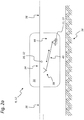
- FIG. 2a illustrates a rear view of the rear side of the vehicle 10 or on the vehicle 10 and spray or AusbringgestCode 12 arranged support portion 13 attached and merely indicated here spray or AusbringgestCode 12, which is rotatably mounted in its suspension point 30.
- This pivot bearing 32 in the suspension point 30 has an axis of rotation which is approximately parallel to the vehicle longitudinal direction 28 (see. Fig. 1 ) is oriented.
- the pivot bearing 32 is not necessarily arranged in the center of gravity of the linkage 12, so that the suspension point 30 may possibly be outside the center of gravity.
- the spray or Ausbringgest briefly 12 includes a central portion 34 with the pivot bearing 32 and both sides attached thereto boom 36, which may be formed either one or more foldable, for example, to be placed in a suitable for a road or transport ride arrangement.
- a plurality of spray nozzles may be arranged on the jibs 36 or extension arms for the uniform and / or controlled discharge of liquid spray or other application material.
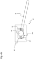
- a linkage 38 for an actuating element 40 which may be configured differently, for example.
- This adjusting element 40 is connected via a vehicle-mounted bearing 44 with the vehicle 12, typically with the frame portion 11 or the support portion 13th
- the middle part 34 can be pivoted together with its arms 36 about the pivot bearing 32, which may be required, for example.
- the actuator 40 When driving along an inclined bottom surface 16 to align the two arms 36 approximately parallel to the bottom surface 16.
- the adjusting element 40 when driving the towing vehicle 10 via a flat bottom surface 16, although a mechanical connection between the linkage 38 on the central part 34 and the vehicle-fixed mounting 44 and the anchoring to the frame portion 11 or on the support portion 13 ago remains this connection even with relative movements and -verschwenkungen of the linkage 12 to the pivot bearing 32 approximately free of displacement or free of Stellmomenten, which is only 40 to ensure almost real-time by a very fast adjusting movement of the control element.
- the reason for this is that the rod 12 - in absolute terms - should remain largely at rest while the vehicle is moving. The resulting unavoidable relative movements and strigkonne of the linkage 12 are detected and taken into account in the control of the control element 40.
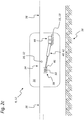
- FIG. 2b illustrates a variant in which the actuator 40 is formed by a hydraulic cylinder 42 or by another linear drive, which is articulated between the articulation 38 on the middle part 34 of the rod 12 and the vehicle-fixed bearing 44 on the frame or support portion 11, 13 of the vehicle 10 ,
- the articulation 38 of the adjusting element 40 and the hydraulic cylinder 42 at the central part 34 of the injection or AusbringgestShes 12 includes in the embodiment shown a largely play-free storage of a one-sided connected to the actuator 40 bolt 50 in a corresponding bolt receptacle. If the agricultural traction vehicle travels over the field soil 16, unevenness in the ground ensures body movements of the traction vehicle, but in which case the spray or application bar 12 should remain largely at rest.
- the adjusting element 40 is formed by a hydraulic cylinder 42 or by another linear drive, which is articulated between the articulation 38 on the middle part 34 of the rod 12 and the vehicle-fixed bearing 44 on the frame or support portion 11, 13 of the vehicle 10.
- the articulation 38 of the adjusting element 40 and the hydraulic cylinder 42 at the central portion 34 of the injection or AusbringgestShes 12 includes in the illustrated embodiment, a game provided with a bearing of the actuator 40 connected to the bolt 50 in a trained as a slot 46 bolt receptacle.
- a suitable sensor system is required, for example, by a mechanical or optical displacement sensor in the region of Bolt bearing 46, 50 may be formed, as determined by the Fig. 3 is explained in more detail.
- the adjusting element 40 is formed by a rotary drive 43 which is articulated between the articulation 38 on the central part 34 of the rod 12 and the vehicle-fixed bearing 44 on the frame or support portion 11, 13 of the vehicle 10.
- the example formed by a hydraulic or electric drive motor rotary drive 43 may optionally be formed as a coaxial with the rotary bearing 32 arranged direct drive or have a gear reduction in order to achieve a torque gain when using a more compact drive motor can.
- a suitable sensor system is required, for example.
- a mechanical or optical displacement sensor in the region of the pin bearing 46, 50 may be formed.
- a sensor can also be integrated in the drive motor in the embodiment shown.
- a sensible variant also consists in detecting the possibly fluctuating torques by evaluating the electrical signals delivered by the electric motor during rotational movements and to obtain values for the torques acting on the motor shaft from these electrical signals.
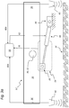
- FIGS. 3a . 3b and 3c show several embodiments of the articulation of the actuating element 40 and the associated sensor 54 for its control.
- sensor device 54 supplies an output signal 56 to a control and / or regulating unit 58, which also processes sensor or setpoint signals 60a and 60b of at least two distance sensors 61, which are respectively arranged on the arms 36 and respectively signal values for a measured distance Provide boom arms 36 to the bottom 16.
- These distance sensors 61 may, for example, be formed by ultrasonic sensors or by optical sensors or the like.
- control and / or regulating unit 58 Based on the sensor signals 60a and 60b and the output signal of the sensor device 54, the control and / or regulating unit 58 generates a control signal 62 for the actuating element 40, which can be controlled in such a way that the mechanical connection between the linkage 38 on the linkage 12 and the vehicle-fixed bearing 44 can be kept approximately force and torque free.
- Fig. 3b embodiment shown corresponds in principle to in Fig. 2b already indicated variant, in which the adjusting element 40 is formed by a double-acting hydraulic cylinder 42 whose piston rod 48 terminates in a pin 50 which is mounted largely free of play in the articulation 38 on the central part 34.
- this articulation 38 may be equipped with a suitable force sensor 54a, which detects the forces transmitted by the bolt 50, generates a first output signal 56a therefrom and thereby the mechanical connection between the bearing 44 and the linkage 38 by means of suitable control of the actuating element 40 via the in the control and / or regulating unit 58 generated control signal 62 holds approximately force and torque free.
- a strain sensor 54b or a suitable force sensor or the like may also be arranged on the piston rod 48 or at another suitable location, which generates a second output signal 56b by detecting the stress and / or strain forces acting on the piston rod 48
- the mechanical connection between the bearing 44 and the linkage 38 by means of suitable control of the actuating element 40 via the control signal generated in the control and / or regulating unit 58 approximately 62 forces and can hold torque-free.
- an inclination sensor 64 can be arranged on the linkage 12, in particular on the middle part 34, the signals of which can additionally be evaluated in the unit 58 in order to be able to obtain a meaningful control signal 62 in connection with the other sensor values mentioned.
- the sensors can also be formed by suitable pressure sensors, which are arranged in the pressure fluid circuit of the control element 40 and, for example, changes in the hydraulic or pneumatic pressure in the region of the control element 40, the hydraulic cylinder 42 and / or the pressure lines are arranged and detect pressure fluctuations, resulting from a relative movement between the spray or AusbringgestShe 12 and the vehicle during pivotal movements about the suspension point 30.
- Fig. 3c embodiment shown corresponds in principle to in Fig. 2c already indicated variant, in which the adjusting element 40 is formed by a double-acting hydraulic cylinder 42 whose piston rod 48 terminates in a pin 50 which is mounted in the articulation 38 on the central part 34 in the slot 46.
- this articulation 38 may be equipped with a suitable optical and / or mechanical displacement sensor 54c, which detects the small deflections of the bolt 50 in the slot 46, generates a third output signal 56c and thereby the mechanical connection between the bearing 44 and the linkage 38 means suitable control of the control element 40 about the control signal generated in the control and / or regulating unit 58 holds approximately forces and moments free.
- the inclination sensor 64 can in the FIGS. 3a and / or 3b illustrated embodiment correspond.
- further sensor types can be used as displacement sensors 54c, for example inductive sensors or rotation detection sensors or the like.
- control and / or regulating unit 58 Depending on the signals 56 and 60, the control and / or regulating unit 58 generates a control signal 62 for a pressure supply unit, not shown here, with which the hydraulic cylinder 42 is in communication. Only the very fast real-time control by means of the control signals 62 can provide the desired freedom of force or torque of the mechanical connection by the actuator 40.
- the control mechanism for the actuator 40 provides this or the double-acting hydraulic cylinder 42 largely without delay all deflections of the vehicle 10 relative to the central part 34 to the pivot bearing 32 in the suspension point 30 after.
- the spray or AusbringgestShe 12 usually performs no independent reaction movements due to vehicle movements, but tends to not follow the vehicle movements and in all vehicle movements (see. Fig. 1 ) remain largely static and at rest.
- This quasi-"real-time” control is thereby able to adjust the cylinder 42 all deflections, but at the same time initiate any significant forces from the vehicle 10 in the middle part 34.
- the control is based on the fact that the forces and / or paths in the articulation 38 are detected and compensated for substantially without delay, so that despite mechanical connection via the actuator 40, the spray or AusbringgestCode 12 remains approximately in the previously set position, regardless of the body movements and variations in the towing vehicle 10 as it passes over the ground 16.
- the control mechanism thus provides for an active "off" control of the rolling movements 26 of the vehicle 10.
- control element 40 or the double-acting fluidic cylinder 42 travel speeds of at least 200 mm / s, in particular more than 400 mm / s can realize.
- a traversing speed of Stellettis 40 or adjusting cylinder 42 of more than 500 mm / s exposed, based on an effective lever length of about 500 mm between linkage 38 and the pivot bearing 32 of the spray or Ausbringgestfites 12th
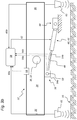
- FIG. 4a The schematic representation of Fig. 4a illustrates again the largely backlash-free storage of the connected to the piston rod 48 of the actuator 40 designed as a linear actuator connected bolt 50 in the receptacle of the linkage 38, which is connected to the central part 34.
- This variant (cf. Fig. 2b . Fig. 3b ) is particularly suitable for the use of an example.
- strain sensor 54b At the piston rod 48 arranged strain sensor 54b.
- FIG. 4b The schematic representation of Fig. 4b further illustrates the play-bearing of the connected to the piston rod 48 of the actuator 40 formed as a linear actuator connected bolt 50 in the slot 46 of the linkage 38, which is connected to the central part 34.
- On both sides of the bolt 50 are force transmission elements such as.
- the illustrated compression springs 52 which provide for the support of the bolt 50 in the slot 46.
- Via a suitable sensor eg sensor 54c; Fig. 3c ), the position of the bolt 50 in the slot 46 is also detected.
- the actuator 40 is driven such that the pin 50 is always approximately centered in the slot 46 and so no restoring forces are transmitted via the springs 52.
- the actuator 40 In the second operating mode, the actuator 40 is driven in such a way that the bolt 50 moves out of the center of the slot 46 by a defined amount. As a result, a defined actuating force is introduced into the linkage 12 via the known spring constants of the compression springs 52, as a result of which this is moved into a desired position.
- the control which is equally effective in the first operating mode is retained and impressed on the control element 40 as a superimposed actuating signal 62, so that all disturbing forces and moments acting on the vehicle can be compensated in the same manner in the adjustment mode.
- the spray or AusbringgestCode 12 is to perform only the predetermined by the bottom inclination pivotal movements about the pivot bearing 32, but not record the vehicle variations, which in particular result from overrun uneven ground. Also in the second operating mode, ie during the pivoting process, the entire scheme maintained as described above, so that only a defined force, which is transmitted via the compression springs 52, specifically initiates the Verschwenkungsvorgang.
Landscapes
- Life Sciences & Earth Sciences (AREA)
- Engineering & Computer Science (AREA)
- Insects & Arthropods (AREA)
- Pest Control & Pesticides (AREA)
- Wood Science & Technology (AREA)
- Zoology (AREA)
- Environmental Sciences (AREA)
- Catching Or Destruction (AREA)
- Vehicle Body Suspensions (AREA)
Priority Applications (4)
| Application Number | Priority Date | Filing Date | Title |
|---|---|---|---|
| PL11188169T PL2591657T3 (pl) | 2011-11-08 | 2011-11-08 | Mobilne urządzenie do rozprowadzania ciekłych i/lub stałych substancji czynnych oraz sposób sterowania urządzeniem |
| EP11188169.4A EP2591657B1 (de) | 2011-11-08 | 2011-11-08 | Fahrbare Vorrichtung zum Ausbringen von flüssigen und/oder festen Wirkstoffen und Verfahren zur Steuerung der Vorrichtung |
| EP17161631.1A EP3219187B1 (de) | 2011-11-08 | 2011-11-08 | Fahrbare vorrichtung zum ausbringen von flüssigen und/oder festen wirkstoffen und verfahren zur steuerung der vorrichtung |
| DK11188169.4T DK2591657T3 (en) | 2011-11-08 | 2011-11-08 | MOVING DEVICE FOR SPREADING FLUID AND / OR SUBSTANCES AND METHOD OF MANAGING SAME DEVICE |
Applications Claiming Priority (1)
| Application Number | Priority Date | Filing Date | Title |
|---|---|---|---|
| EP11188169.4A EP2591657B1 (de) | 2011-11-08 | 2011-11-08 | Fahrbare Vorrichtung zum Ausbringen von flüssigen und/oder festen Wirkstoffen und Verfahren zur Steuerung der Vorrichtung |
Related Child Applications (2)
| Application Number | Title | Priority Date | Filing Date |
|---|---|---|---|
| EP17161631.1A Division EP3219187B1 (de) | 2011-11-08 | 2011-11-08 | Fahrbare vorrichtung zum ausbringen von flüssigen und/oder festen wirkstoffen und verfahren zur steuerung der vorrichtung |
| EP17161631.1A Division-Into EP3219187B1 (de) | 2011-11-08 | 2011-11-08 | Fahrbare vorrichtung zum ausbringen von flüssigen und/oder festen wirkstoffen und verfahren zur steuerung der vorrichtung |
Publications (2)
| Publication Number | Publication Date |
|---|---|
| EP2591657A1 EP2591657A1 (de) | 2013-05-15 |
| EP2591657B1 true EP2591657B1 (de) | 2017-06-28 |
Family
ID=45001654
Family Applications (2)
| Application Number | Title | Priority Date | Filing Date |
|---|---|---|---|
| EP11188169.4A Revoked EP2591657B1 (de) | 2011-11-08 | 2011-11-08 | Fahrbare Vorrichtung zum Ausbringen von flüssigen und/oder festen Wirkstoffen und Verfahren zur Steuerung der Vorrichtung |
| EP17161631.1A Active EP3219187B1 (de) | 2011-11-08 | 2011-11-08 | Fahrbare vorrichtung zum ausbringen von flüssigen und/oder festen wirkstoffen und verfahren zur steuerung der vorrichtung |
Family Applications After (1)
| Application Number | Title | Priority Date | Filing Date |
|---|---|---|---|
| EP17161631.1A Active EP3219187B1 (de) | 2011-11-08 | 2011-11-08 | Fahrbare vorrichtung zum ausbringen von flüssigen und/oder festen wirkstoffen und verfahren zur steuerung der vorrichtung |
Country Status (3)
| Country | Link |
|---|---|
| EP (2) | EP2591657B1 (pl) |
| DK (1) | DK2591657T3 (pl) |
| PL (1) | PL2591657T3 (pl) |
Cited By (3)
| Publication number | Priority date | Publication date | Assignee | Title |
|---|---|---|---|---|
| EP3791717A1 (de) | 2019-08-28 | 2021-03-17 | HORSCH LEEB Application Systems GmbH | Landwirtschaftliche verteilmaschine, vorzugsweise eine feldspritze oder ein düngerstreuer |
| EP3804516A1 (de) | 2019-10-10 | 2021-04-14 | HORSCH LEEB Application Systems GmbH | Landwirtschaftliche verteilmaschine, vorzugsweise eine feldspritze oder ein düngerstreuer |
| EP3804515A1 (de) | 2019-10-10 | 2021-04-14 | HORSCH LEEB Application Systems GmbH | Landwirtschaftliche verteilmaschine, vorzugsweise eine feldspritze oder einen pneumatischen düngerstreuer |
Families Citing this family (18)
| Publication number | Priority date | Publication date | Assignee | Title |
|---|---|---|---|---|
| PL2591657T3 (pl) | 2011-11-08 | 2017-12-29 | Horsch Leeb Application Systems Gmbh | Mobilne urządzenie do rozprowadzania ciekłych i/lub stałych substancji czynnych oraz sposób sterowania urządzeniem |
| WO2015025015A1 (de) | 2013-08-22 | 2015-02-26 | Horsch Leeb Application Systems Gmbh | Verfahren zur bewegungssteuerung und/oder regelung einer landwirtschaftlichen verteilvorrichtung |
| DK2839740T3 (en) | 2013-08-22 | 2017-05-01 | Horsch Leeb Application Systems Gmbh | PROCEDURE FOR MOVEMENT MANAGEMENT AND / OR REGULATION OF A AGRICULTURAL DISTRIBUTION DEVICE |
| EP3183963B1 (de) | 2013-09-18 | 2018-05-16 | HORSCH LEEB Application Systems GmbH | Vorrichtung zum ausbringen von flüssigen und/oder festen wirkstoffen und verfahren zur steuerung einer solchen vorrichtung |
| EP3035795B1 (de) * | 2013-10-14 | 2020-11-18 | HORSCH LEEB Application Systems GmbH | Feldspritze zum ausbringen von flüssigen und/oder festen wirkstoffen und regelung zur steuerung derselben |
| DK3065530T3 (da) * | 2013-11-10 | 2022-06-13 | Horsch Leeb Application Systems Gmbh | Apparat til udbringning af flydende og/eller faste virkestoffer og fremgangsmåde til styring af et sådant apparat |
| DE102014105416A1 (de) | 2014-04-16 | 2015-10-22 | Amazonen-Werke H. Dreyer Gmbh & Co. Kg | Ausbringfahrzeug |
| DE102014111090A1 (de) | 2014-08-05 | 2016-02-11 | Amazonen-Werke H. Dreyer Gmbh & Co. Kg | Vorrichtung und Verfahren zur Bewegungssteuerung eines Verteilergestänges einer landwirtschaftlichen Verteilmaschine |
| DE102015102422A1 (de) | 2015-02-20 | 2016-08-25 | Horsch Leeb Application Systems Gmbh | Verfahren zur Bewegungssteuerung und/oder Regelung einer landwirtschaftlichen Verteilvorrichtung |
| DE102015102975A1 (de) * | 2015-03-02 | 2016-09-08 | Horsch Leeb Application Systems Gmbh | Vorrichtung zum Ausbringen von flüssigen und/oder festen Wirkstoffen und Verfahren zur Steuerung einer solchen Vorrichtung |
| FI127225B (fi) * | 2016-06-21 | 2018-01-31 | W-Cult Oy | Puomijärjestely ja menetelmä puomijärjestelyn kallistusasennon säätämiseksi |
| DE102017201918A1 (de) | 2017-02-07 | 2018-08-09 | Deere & Company | Landwirtschaftliche Verteilmaschine mit selbsttätiger Kontrolle der Dämpfung des Verteilergestänges |
| DE102018106538A1 (de) | 2018-03-20 | 2019-09-26 | Horsch Leeb Application Systems Gmbh | Landwirtschaftliche verteilmaschine und verfahren zum ausbringen von flüssigen wirkstoffen |
| DE102020123308A1 (de) | 2020-09-07 | 2022-03-10 | Horsch Leeb Application Systems Gmbh | Landwirtschaftliche Feldspritze und Spritzvorrichtung für eine landwirtschaftliche Feldspritze |
| DE102021002610A1 (de) * | 2021-05-18 | 2022-11-24 | Hydac Mobilhydraulik Gmbh | Fahrbare Arbeitsmaschine |
| DE102022109092A1 (de) | 2022-04-13 | 2023-10-19 | Horsch Leeb Application Systems Gmbh | Landwirtschaftliche verteilmaschine mit einem verteilgestänge und verfahren zur lagesteuerung des verteilgestänges |
| DE102022109091A1 (de) | 2022-04-13 | 2023-10-19 | Horsch Leeb Application Systems Gmbh | Landwirtschaftliche verteilmaschine mit einem verteilgestänge und verfahren zur lagesteuerung des verteilgestänges |
| CN119111214B (zh) * | 2024-10-30 | 2025-03-21 | 西安嘉农环境科技有限公司 | 一种农业种植用均匀施肥装置 |
Citations (23)
| Publication number | Priority date | Publication date | Assignee | Title |
|---|---|---|---|---|
| DE1833453U (de) | 1961-02-06 | 1961-06-22 | Fritz Dr Reichle | Spritzgestell fuer pflanzenschutzgeraete. |
| FR2270774A1 (en) | 1974-05-15 | 1975-12-12 | Berthoud Sa | Suspension for agricultural spray boom - has lifting jack pivotal by shock absorbing side jacks |
| FR2520264A1 (fr) | 1982-01-28 | 1983-07-29 | Seguip | Dispositif de suppport de rampes de pulverisation agricole |
| DE3202569A1 (de) | 1982-01-27 | 1983-08-04 | Amazonen-Werke H. Dreyer Gmbh & Co Kg, 4507 Hasbergen | Verteilmaschine mit einem verteilergestaenge |
| US4522841A (en) | 1981-10-09 | 1985-06-11 | Centre National Du Machinisme Agricole, Du Genie Rural, Des Eaux Et Des Forets (Cemagref) | Process for the stabilization with respect to a desired path of a member which is movably mounted according to at least one component of movement and its application to the stabilization of a spray manifold |
| EP0157592A2 (en) | 1984-03-27 | 1985-10-09 | Btg International Limited | Boom assemblies |
| FR2562378A1 (fr) | 1984-04-05 | 1985-10-11 | Nodet Gougis | Dispositif de regulation automatique de l'attitude d'un accessoire de machine agricole tel qu'une rampe de pulverisation |
| EP0193010A2 (de) | 1985-02-26 | 1986-09-03 | SCHMOTZER AGRARTECHNIC GmbH | An einem Fahrzeug aufgehängte Verteil- oder Sprüheinrichtung |
| FR2669804A1 (fr) | 1990-11-29 | 1992-06-05 | Agro Electronique France | Dispositif de rappel automatique en position de reference d'une rampe de distribution de produit liquide ou en poudre pour machine agricole du type pulverisateur ou distributeur d'engrais. |
| DE4140254A1 (de) | 1991-10-22 | 1993-06-09 | Gerd E. F. 8608 Memmelsdorf De Steffen | Ultraschallgefuehrte spritze fuer die landwirtschaft |
| EP0922385A1 (de) | 1997-12-10 | 1999-06-16 | Amazonen-Werke H. Dreyer GmbH & Co. KG | Landwirtschaftliche Maschine zum Verteilen von Material, vorzugsweise Feldspritze |
| FR2779031A1 (fr) | 1998-06-02 | 1999-12-03 | Exel Ind | Ensemble de rampe pendulaire, notamment pour engin de pulverisation agricole, equipe d'un dispositif de correction d'inclinaison |
| WO2001003503A1 (fr) | 1999-07-09 | 2001-01-18 | Michel Barrau | Dispositif de controle automatique de niveau d'inclinaison d'une rampe de pulverisation |
| JP2001204357A (ja) | 2000-01-26 | 2001-07-31 | Iseki & Co Ltd | 防除作業機のブ−ム水平制御装置 |
| JP2004089012A (ja) | 2002-08-29 | 2004-03-25 | Iseki & Co Ltd | 作業機の姿勢制御装置 |
| WO2004041446A1 (en) | 2002-11-07 | 2004-05-21 | Mark Ellsworth | Crop spraying device |
| JP2004194618A (ja) | 2002-12-20 | 2004-07-15 | Iseki & Co Ltd | 薬剤散布装置の水平制御装置 |
| EP1444894A1 (en) | 2003-02-10 | 2004-08-11 | Norac Systems International Inc. | Roll control system and method for a suspended boom |
| DE202007011631U1 (de) | 2006-12-11 | 2007-10-18 | Leeb Mechanik Gmbh | Aufhängevorrichtung für ein ausladendes landwirtschaftliches Anbaugerät |
| DE102007025751A1 (de) | 2007-06-01 | 2008-12-04 | Amazonen-Werke H. Dreyer Gmbh & Co. Kg | Verteilmaschine |
| EP2042276A2 (de) | 2007-09-26 | 2009-04-01 | Deere & Company | Landwirtschaftliche Maschine und Verfahren zur Positionsbestimmung |
| EP2064948A2 (de) | 2007-11-28 | 2009-06-03 | John Deere Fabriek Horst B.V. | Spritzengestänge |
| EP2591657A1 (de) | 2011-11-08 | 2013-05-15 | HORSCH LEEB Application Systems GmbH | Fahrbare Vorrichtung zum Ausbringen von flüssigen und/oder festen Wirkstoffen und Verfahren zur Steuerung der Vorrichtung |
-
2011
- 2011-11-08 PL PL11188169T patent/PL2591657T3/pl unknown
- 2011-11-08 EP EP11188169.4A patent/EP2591657B1/de not_active Revoked
- 2011-11-08 EP EP17161631.1A patent/EP3219187B1/de active Active
- 2011-11-08 DK DK11188169.4T patent/DK2591657T3/en active
Patent Citations (23)
| Publication number | Priority date | Publication date | Assignee | Title |
|---|---|---|---|---|
| DE1833453U (de) | 1961-02-06 | 1961-06-22 | Fritz Dr Reichle | Spritzgestell fuer pflanzenschutzgeraete. |
| FR2270774A1 (en) | 1974-05-15 | 1975-12-12 | Berthoud Sa | Suspension for agricultural spray boom - has lifting jack pivotal by shock absorbing side jacks |
| US4522841A (en) | 1981-10-09 | 1985-06-11 | Centre National Du Machinisme Agricole, Du Genie Rural, Des Eaux Et Des Forets (Cemagref) | Process for the stabilization with respect to a desired path of a member which is movably mounted according to at least one component of movement and its application to the stabilization of a spray manifold |
| DE3202569A1 (de) | 1982-01-27 | 1983-08-04 | Amazonen-Werke H. Dreyer Gmbh & Co Kg, 4507 Hasbergen | Verteilmaschine mit einem verteilergestaenge |
| FR2520264A1 (fr) | 1982-01-28 | 1983-07-29 | Seguip | Dispositif de suppport de rampes de pulverisation agricole |
| EP0157592A2 (en) | 1984-03-27 | 1985-10-09 | Btg International Limited | Boom assemblies |
| FR2562378A1 (fr) | 1984-04-05 | 1985-10-11 | Nodet Gougis | Dispositif de regulation automatique de l'attitude d'un accessoire de machine agricole tel qu'une rampe de pulverisation |
| EP0193010A2 (de) | 1985-02-26 | 1986-09-03 | SCHMOTZER AGRARTECHNIC GmbH | An einem Fahrzeug aufgehängte Verteil- oder Sprüheinrichtung |
| FR2669804A1 (fr) | 1990-11-29 | 1992-06-05 | Agro Electronique France | Dispositif de rappel automatique en position de reference d'une rampe de distribution de produit liquide ou en poudre pour machine agricole du type pulverisateur ou distributeur d'engrais. |
| DE4140254A1 (de) | 1991-10-22 | 1993-06-09 | Gerd E. F. 8608 Memmelsdorf De Steffen | Ultraschallgefuehrte spritze fuer die landwirtschaft |
| EP0922385A1 (de) | 1997-12-10 | 1999-06-16 | Amazonen-Werke H. Dreyer GmbH & Co. KG | Landwirtschaftliche Maschine zum Verteilen von Material, vorzugsweise Feldspritze |
| FR2779031A1 (fr) | 1998-06-02 | 1999-12-03 | Exel Ind | Ensemble de rampe pendulaire, notamment pour engin de pulverisation agricole, equipe d'un dispositif de correction d'inclinaison |
| WO2001003503A1 (fr) | 1999-07-09 | 2001-01-18 | Michel Barrau | Dispositif de controle automatique de niveau d'inclinaison d'une rampe de pulverisation |
| JP2001204357A (ja) | 2000-01-26 | 2001-07-31 | Iseki & Co Ltd | 防除作業機のブ−ム水平制御装置 |
| JP2004089012A (ja) | 2002-08-29 | 2004-03-25 | Iseki & Co Ltd | 作業機の姿勢制御装置 |
| WO2004041446A1 (en) | 2002-11-07 | 2004-05-21 | Mark Ellsworth | Crop spraying device |
| JP2004194618A (ja) | 2002-12-20 | 2004-07-15 | Iseki & Co Ltd | 薬剤散布装置の水平制御装置 |
| EP1444894A1 (en) | 2003-02-10 | 2004-08-11 | Norac Systems International Inc. | Roll control system and method for a suspended boom |
| DE202007011631U1 (de) | 2006-12-11 | 2007-10-18 | Leeb Mechanik Gmbh | Aufhängevorrichtung für ein ausladendes landwirtschaftliches Anbaugerät |
| DE102007025751A1 (de) | 2007-06-01 | 2008-12-04 | Amazonen-Werke H. Dreyer Gmbh & Co. Kg | Verteilmaschine |
| EP2042276A2 (de) | 2007-09-26 | 2009-04-01 | Deere & Company | Landwirtschaftliche Maschine und Verfahren zur Positionsbestimmung |
| EP2064948A2 (de) | 2007-11-28 | 2009-06-03 | John Deere Fabriek Horst B.V. | Spritzengestänge |
| EP2591657A1 (de) | 2011-11-08 | 2013-05-15 | HORSCH LEEB Application Systems GmbH | Fahrbare Vorrichtung zum Ausbringen von flüssigen und/oder festen Wirkstoffen und Verfahren zur Steuerung der Vorrichtung |
Non-Patent Citations (3)
| Title |
|---|
| "Echtzeit", WIKIPEDIA, 27 August 2011 (2011-08-27), XP055477016, Retrieved from the Internet <URL:de.wikipedia.org_Echtzeit> |
| "Fuzzylogik", WIKEPIDIA, 2 November 2011 (2011-11-02), XP055477015, Retrieved from the Internet <URL:de.wikipedia.org> |
| NORAC: "NORAC UC5 Spray Height Control System", INSTALLATION MANUAL, 2008, XP055477209 |
Cited By (3)
| Publication number | Priority date | Publication date | Assignee | Title |
|---|---|---|---|---|
| EP3791717A1 (de) | 2019-08-28 | 2021-03-17 | HORSCH LEEB Application Systems GmbH | Landwirtschaftliche verteilmaschine, vorzugsweise eine feldspritze oder ein düngerstreuer |
| EP3804516A1 (de) | 2019-10-10 | 2021-04-14 | HORSCH LEEB Application Systems GmbH | Landwirtschaftliche verteilmaschine, vorzugsweise eine feldspritze oder ein düngerstreuer |
| EP3804515A1 (de) | 2019-10-10 | 2021-04-14 | HORSCH LEEB Application Systems GmbH | Landwirtschaftliche verteilmaschine, vorzugsweise eine feldspritze oder einen pneumatischen düngerstreuer |
Also Published As
| Publication number | Publication date |
|---|---|
| EP3219187B1 (de) | 2023-10-04 |
| DK2591657T3 (en) | 2017-10-02 |
| PL2591657T3 (pl) | 2017-12-29 |
| EP2591657A1 (de) | 2013-05-15 |
| EP3219187A1 (de) | 2017-09-20 |
Similar Documents
| Publication | Publication Date | Title |
|---|---|---|
| EP2591657B1 (de) | Fahrbare Vorrichtung zum Ausbringen von flüssigen und/oder festen Wirkstoffen und Verfahren zur Steuerung der Vorrichtung | |
| EP3065530B1 (de) | Vorrichtung zum ausbringen von flüssigen und/oder festen wirkstoffen und verfahren zur steuerung einer solchen vorrichtung | |
| EP3207798B1 (de) | Vorrichtung zum ausbringen von flüssigen und/oder festen wirkstoffen und verfahren zur steuerung einer solchen vorrichtung | |
| EP3797588B1 (de) | Verfahren zur bewegungssteuerung und/oder regelung einer landwirtschaftlichen verteilvorrichtung | |
| EP2186405B1 (de) | Spritzgestänge und Verfahren zu dessen Steuerung | |
| EP2829177B1 (de) | Landwirtschaftliche Verteilmaschine mit Verteilvorrichtung und System zur Steuerung der Verteilvorrichtung | |
| EP3462855B1 (de) | Regel- und/oder steuersystem, landwirtschaftliche maschine mit einem solchen system und verfahren zum betreiben einer landwirtschaftlichen maschine | |
| EP3064061A1 (de) | Vorrichtung zum ausbringen von flüssigen und/oder festen wirkstoffen und verfahren zur steuerung einer solchen vorrichtung | |
| EP2839740B1 (de) | Verfahren zur Bewegungssteuerung und/oder Regelung einer landwirtschaftlichen Verteilvorrichtung | |
| EP2837285B1 (de) | Spritzgestänge einer landwirtschaftlichen Feldspritze | |
| DE102015101032A1 (de) | Landwirtschaftliche Maschine und Regelungsverfahren | |
| EP3141114B1 (de) | Flächenausbringanordnung sowie flächenausbringsteuerungsverfahren | |
| DE202013011983U1 (de) | Spritzgestänge einer landwirtschaftlichen Feldspritze | |
| EP3035794B1 (de) | Verfahren zur bewegungssteuerung und/oder regelung einer landwirtschaftlichen verteilvorrichtung | |
| EP2936980A1 (de) | Feldspritze | |
| EP3437470A1 (de) | Feldspritze und ausbringausleger für eine feldspritze | |
| DE102018103862A1 (de) | Aufhängung für eine landwirtschaftliche Maschine und Verfahren zum Betreiben einer landwirtschaftlichen Maschine | |
| DE102018213458B4 (de) | Landwirtschaftliche Verteilmaschine mit Verteilgestänge | |
| EP4620301A1 (de) | Landwirtschaftliche verteilmaschine | |
| EP4477046A1 (de) | Tragstruktur für ein landwirtschaftliches arbeitsgerät zur ausbringung eines landwirtschaftlichen guts auf einem boden, arbeitsgerät mit einer tragstruktur und verfahren zum ausbringen eines landwirtschaftlichen guts |
Legal Events
| Date | Code | Title | Description |
|---|---|---|---|
| PUAI | Public reference made under article 153(3) epc to a published international application that has entered the european phase |
Free format text: ORIGINAL CODE: 0009012 |
|
| AK | Designated contracting states |
Kind code of ref document: A1 Designated state(s): AL AT BE BG CH CY CZ DE DK EE ES FI FR GB GR HR HU IE IS IT LI LT LU LV MC MK MT NL NO PL PT RO RS SE SI SK SM TR |
|
| AX | Request for extension of the european patent |
Extension state: BA ME |
|
| 17P | Request for examination filed |
Effective date: 20130715 |
|
| RBV | Designated contracting states (corrected) |
Designated state(s): AL AT BE BG CH CY CZ DE DK EE ES FI FR GB GR HR HU IE IS IT LI LT LU LV MC MK MT NL NO PL PT RO RS SE SI SK SM TR |
|
| TPAC | Observations filed by third parties |
Free format text: ORIGINAL CODE: EPIDOSNTIPA |
|
| 17Q | First examination report despatched |
Effective date: 20151223 |
|
| TPAC | Observations filed by third parties |
Free format text: ORIGINAL CODE: EPIDOSNTIPA |
|
| TPAC | Observations filed by third parties |
Free format text: ORIGINAL CODE: EPIDOSNTIPA |
|
| GRAP | Despatch of communication of intention to grant a patent |
Free format text: ORIGINAL CODE: EPIDOSNIGR1 |
|
| STAA | Information on the status of an ep patent application or granted ep patent |
Free format text: STATUS: GRANT OF PATENT IS INTENDED |
|
| INTG | Intention to grant announced |
Effective date: 20170124 |
|
| GRAS | Grant fee paid |
Free format text: ORIGINAL CODE: EPIDOSNIGR3 |
|
| GRAA | (expected) grant |
Free format text: ORIGINAL CODE: 0009210 |
|
| STAA | Information on the status of an ep patent application or granted ep patent |
Free format text: STATUS: THE PATENT HAS BEEN GRANTED |
|
| AK | Designated contracting states |
Kind code of ref document: B1 Designated state(s): AL AT BE BG CH CY CZ DE DK EE ES FI FR GB GR HR HU IE IS IT LI LT LU LV MC MK MT NL NO PL PT RO RS SE SI SK SM TR |
|
| REG | Reference to a national code |
Ref country code: GB Ref legal event code: FG4D Free format text: NOT ENGLISH |
|
| REG | Reference to a national code |
Ref country code: CH Ref legal event code: EP |
|
| REG | Reference to a national code |
Ref country code: AT Ref legal event code: REF Ref document number: 903993 Country of ref document: AT Kind code of ref document: T Effective date: 20170715 |
|
| REG | Reference to a national code |
Ref country code: IE Ref legal event code: FG4D Free format text: LANGUAGE OF EP DOCUMENT: GERMAN |
|
| REG | Reference to a national code |
Ref country code: DE Ref legal event code: R096 Ref document number: 502011012510 Country of ref document: DE |
|
| REG | Reference to a national code |
Ref country code: NL Ref legal event code: FP |
|
| REG | Reference to a national code |
Ref country code: DK Ref legal event code: T3 Effective date: 20170928 |
|
| REG | Reference to a national code |
Ref country code: SE Ref legal event code: TRGR |
|
| PG25 | Lapsed in a contracting state [announced via postgrant information from national office to epo] |
Ref country code: NO Free format text: LAPSE BECAUSE OF FAILURE TO SUBMIT A TRANSLATION OF THE DESCRIPTION OR TO PAY THE FEE WITHIN THE PRESCRIBED TIME-LIMIT Effective date: 20170928 Ref country code: LT Free format text: LAPSE BECAUSE OF FAILURE TO SUBMIT A TRANSLATION OF THE DESCRIPTION OR TO PAY THE FEE WITHIN THE PRESCRIBED TIME-LIMIT Effective date: 20170628 Ref country code: HR Free format text: LAPSE BECAUSE OF FAILURE TO SUBMIT A TRANSLATION OF THE DESCRIPTION OR TO PAY THE FEE WITHIN THE PRESCRIBED TIME-LIMIT Effective date: 20170628 Ref country code: FI Free format text: LAPSE BECAUSE OF FAILURE TO SUBMIT A TRANSLATION OF THE DESCRIPTION OR TO PAY THE FEE WITHIN THE PRESCRIBED TIME-LIMIT Effective date: 20170628 Ref country code: GR Free format text: LAPSE BECAUSE OF FAILURE TO SUBMIT A TRANSLATION OF THE DESCRIPTION OR TO PAY THE FEE WITHIN THE PRESCRIBED TIME-LIMIT Effective date: 20170929 |
|
| REG | Reference to a national code |
Ref country code: LT Ref legal event code: MG4D |
|
| REG | Reference to a national code |
Ref country code: FR Ref legal event code: PLFP Year of fee payment: 7 |
|
| PG25 | Lapsed in a contracting state [announced via postgrant information from national office to epo] |
Ref country code: LV Free format text: LAPSE BECAUSE OF FAILURE TO SUBMIT A TRANSLATION OF THE DESCRIPTION OR TO PAY THE FEE WITHIN THE PRESCRIBED TIME-LIMIT Effective date: 20170628 Ref country code: RS Free format text: LAPSE BECAUSE OF FAILURE TO SUBMIT A TRANSLATION OF THE DESCRIPTION OR TO PAY THE FEE WITHIN THE PRESCRIBED TIME-LIMIT Effective date: 20170628 Ref country code: BG Free format text: LAPSE BECAUSE OF FAILURE TO SUBMIT A TRANSLATION OF THE DESCRIPTION OR TO PAY THE FEE WITHIN THE PRESCRIBED TIME-LIMIT Effective date: 20170928 |
|
| PG25 | Lapsed in a contracting state [announced via postgrant information from national office to epo] |
Ref country code: RO Free format text: LAPSE BECAUSE OF FAILURE TO SUBMIT A TRANSLATION OF THE DESCRIPTION OR TO PAY THE FEE WITHIN THE PRESCRIBED TIME-LIMIT Effective date: 20170628 Ref country code: SK Free format text: LAPSE BECAUSE OF FAILURE TO SUBMIT A TRANSLATION OF THE DESCRIPTION OR TO PAY THE FEE WITHIN THE PRESCRIBED TIME-LIMIT Effective date: 20170628 Ref country code: EE Free format text: LAPSE BECAUSE OF FAILURE TO SUBMIT A TRANSLATION OF THE DESCRIPTION OR TO PAY THE FEE WITHIN THE PRESCRIBED TIME-LIMIT Effective date: 20170628 |
|
| PG25 | Lapsed in a contracting state [announced via postgrant information from national office to epo] |
Ref country code: ES Free format text: LAPSE BECAUSE OF FAILURE TO SUBMIT A TRANSLATION OF THE DESCRIPTION OR TO PAY THE FEE WITHIN THE PRESCRIBED TIME-LIMIT Effective date: 20170628 Ref country code: SM Free format text: LAPSE BECAUSE OF FAILURE TO SUBMIT A TRANSLATION OF THE DESCRIPTION OR TO PAY THE FEE WITHIN THE PRESCRIBED TIME-LIMIT Effective date: 20170628 Ref country code: IS Free format text: LAPSE BECAUSE OF FAILURE TO SUBMIT A TRANSLATION OF THE DESCRIPTION OR TO PAY THE FEE WITHIN THE PRESCRIBED TIME-LIMIT Effective date: 20171028 |
|
| REG | Reference to a national code |
Ref country code: DE Ref legal event code: R026 Ref document number: 502011012510 Country of ref document: DE |
|
| PLBI | Opposition filed |
Free format text: ORIGINAL CODE: 0009260 |
|
| PLBI | Opposition filed |
Free format text: ORIGINAL CODE: 0009260 |
|
| PLAX | Notice of opposition and request to file observation + time limit sent |
Free format text: ORIGINAL CODE: EPIDOSNOBS2 |
|
| 26 | Opposition filed |
Opponent name: HARDI INTERNATIONAL A/S Effective date: 20180327 Opponent name: HERBERT DAMMANN GMBH Effective date: 20180328 Opponent name: AMAZONEN-WERKE H. DREYER GMBH & CO. KG Effective date: 20180326 |
|
| 26 | Opposition filed |
Opponent name: TOPCON POSITIONING SYSTEMS, INC. Effective date: 20180328 |
|
| PLAF | Information modified related to communication of a notice of opposition and request to file observations + time limit |
Free format text: ORIGINAL CODE: EPIDOSCOBS2 |
|
| PG25 | Lapsed in a contracting state [announced via postgrant information from national office to epo] |
Ref country code: MC Free format text: LAPSE BECAUSE OF FAILURE TO SUBMIT A TRANSLATION OF THE DESCRIPTION OR TO PAY THE FEE WITHIN THE PRESCRIBED TIME-LIMIT Effective date: 20170628 |
|
| REG | Reference to a national code |
Ref country code: DE Ref legal event code: R082 Ref document number: 502011012510 Country of ref document: DE Representative=s name: V. BEZOLD & PARTNER PATENTANWAELTE - PARTG MBB, DE |
|
| PG25 | Lapsed in a contracting state [announced via postgrant information from national office to epo] |
Ref country code: LI Free format text: LAPSE BECAUSE OF NON-PAYMENT OF DUE FEES Effective date: 20171130 Ref country code: CH Free format text: LAPSE BECAUSE OF NON-PAYMENT OF DUE FEES Effective date: 20171130 |
|
| PG25 | Lapsed in a contracting state [announced via postgrant information from national office to epo] |
Ref country code: SI Free format text: LAPSE BECAUSE OF FAILURE TO SUBMIT A TRANSLATION OF THE DESCRIPTION OR TO PAY THE FEE WITHIN THE PRESCRIBED TIME-LIMIT Effective date: 20170628 Ref country code: LU Free format text: LAPSE BECAUSE OF NON-PAYMENT OF DUE FEES Effective date: 20171108 |
|
| REG | Reference to a national code |
Ref country code: BE Ref legal event code: MM Effective date: 20171130 |
|
| REG | Reference to a national code |
Ref country code: IE Ref legal event code: MM4A |
|
| PG25 | Lapsed in a contracting state [announced via postgrant information from national office to epo] |
Ref country code: MT Free format text: LAPSE BECAUSE OF FAILURE TO SUBMIT A TRANSLATION OF THE DESCRIPTION OR TO PAY THE FEE WITHIN THE PRESCRIBED TIME-LIMIT Effective date: 20170628 |
|
| PLBB | Reply of patent proprietor to notice(s) of opposition received |
Free format text: ORIGINAL CODE: EPIDOSNOBS3 |
|
| PG25 | Lapsed in a contracting state [announced via postgrant information from national office to epo] |
Ref country code: IE Free format text: LAPSE BECAUSE OF NON-PAYMENT OF DUE FEES Effective date: 20171108 |
|
| PG25 | Lapsed in a contracting state [announced via postgrant information from national office to epo] |
Ref country code: BE Free format text: LAPSE BECAUSE OF NON-PAYMENT OF DUE FEES Effective date: 20171130 |
|
| REG | Reference to a national code |
Ref country code: AT Ref legal event code: MM01 Ref document number: 903993 Country of ref document: AT Kind code of ref document: T Effective date: 20171108 |
|
| PG25 | Lapsed in a contracting state [announced via postgrant information from national office to epo] |
Ref country code: AT Free format text: LAPSE BECAUSE OF NON-PAYMENT OF DUE FEES Effective date: 20171108 |
|
| PG25 | Lapsed in a contracting state [announced via postgrant information from national office to epo] |
Ref country code: HU Free format text: LAPSE BECAUSE OF FAILURE TO SUBMIT A TRANSLATION OF THE DESCRIPTION OR TO PAY THE FEE WITHIN THE PRESCRIBED TIME-LIMIT; INVALID AB INITIO Effective date: 20111108 |
|
| PG25 | Lapsed in a contracting state [announced via postgrant information from national office to epo] |
Ref country code: CY Free format text: LAPSE BECAUSE OF NON-PAYMENT OF DUE FEES Effective date: 20170628 |
|
| PG25 | Lapsed in a contracting state [announced via postgrant information from national office to epo] |
Ref country code: MK Free format text: LAPSE BECAUSE OF FAILURE TO SUBMIT A TRANSLATION OF THE DESCRIPTION OR TO PAY THE FEE WITHIN THE PRESCRIBED TIME-LIMIT Effective date: 20170628 |
|
| APAH | Appeal reference modified |
Free format text: ORIGINAL CODE: EPIDOSCREFNO |
|
| APBM | Appeal reference recorded |
Free format text: ORIGINAL CODE: EPIDOSNREFNO |
|
| APBP | Date of receipt of notice of appeal recorded |
Free format text: ORIGINAL CODE: EPIDOSNNOA2O |
|
| PG25 | Lapsed in a contracting state [announced via postgrant information from national office to epo] |
Ref country code: TR Free format text: LAPSE BECAUSE OF FAILURE TO SUBMIT A TRANSLATION OF THE DESCRIPTION OR TO PAY THE FEE WITHIN THE PRESCRIBED TIME-LIMIT Effective date: 20170628 |
|
| APBM | Appeal reference recorded |
Free format text: ORIGINAL CODE: EPIDOSNREFNO |
|
| APBP | Date of receipt of notice of appeal recorded |
Free format text: ORIGINAL CODE: EPIDOSNNOA2O |
|
| REG | Reference to a national code |
Ref country code: DE Ref legal event code: R082 Ref document number: 502011012510 Country of ref document: DE Representative=s name: V. BEZOLD & PARTNER PATENTANWAELTE - PARTG MBB, DE Ref country code: DE Ref legal event code: R081 Ref document number: 502011012510 Country of ref document: DE Owner name: HORSCH LEEB APPLICATION SYSTEMS GMBH, DE Free format text: FORMER OWNER: HORSCH LEEB APPLICATION SYSTEMS GMBH, 94562 OBERPOERING, DE |
|
| PG25 | Lapsed in a contracting state [announced via postgrant information from national office to epo] |
Ref country code: PT Free format text: LAPSE BECAUSE OF FAILURE TO SUBMIT A TRANSLATION OF THE DESCRIPTION OR TO PAY THE FEE WITHIN THE PRESCRIBED TIME-LIMIT Effective date: 20170628 |
|
| RAP2 | Party data changed (patent owner data changed or rights of a patent transferred) |
Owner name: HORSCH LEEB APPLICATION SYSTEMS GMBH |
|
| APBQ | Date of receipt of statement of grounds of appeal recorded |
Free format text: ORIGINAL CODE: EPIDOSNNOA3O |
|
| APBQ | Date of receipt of statement of grounds of appeal recorded |
Free format text: ORIGINAL CODE: EPIDOSNNOA3O |
|
| PG25 | Lapsed in a contracting state [announced via postgrant information from national office to epo] |
Ref country code: AL Free format text: LAPSE BECAUSE OF FAILURE TO SUBMIT A TRANSLATION OF THE DESCRIPTION OR TO PAY THE FEE WITHIN THE PRESCRIBED TIME-LIMIT Effective date: 20170628 |
|
| PLAB | Opposition data, opponent's data or that of the opponent's representative modified |
Free format text: ORIGINAL CODE: 0009299OPPO |
|
| R26 | Opposition filed (corrected) |
Opponent name: HERBERT DAMMANN GMBH Effective date: 20180328 |
|
| PLBP | Opposition withdrawn |
Free format text: ORIGINAL CODE: 0009264 |
|
| REG | Reference to a national code |
Ref country code: DE Ref legal event code: R103 Ref document number: 502011012510 Country of ref document: DE Ref country code: DE Ref legal event code: R064 Ref document number: 502011012510 Country of ref document: DE |
|
| APBU | Appeal procedure closed |
Free format text: ORIGINAL CODE: EPIDOSNNOA9O |
|
| PGFP | Annual fee paid to national office [announced via postgrant information from national office to epo] |
Ref country code: SE Payment date: 20221122 Year of fee payment: 12 Ref country code: NL Payment date: 20221118 Year of fee payment: 12 Ref country code: IT Payment date: 20221130 Year of fee payment: 12 Ref country code: GB Payment date: 20221123 Year of fee payment: 12 Ref country code: FR Payment date: 20221121 Year of fee payment: 12 Ref country code: DK Payment date: 20221122 Year of fee payment: 12 Ref country code: DE Payment date: 20221107 Year of fee payment: 12 Ref country code: CZ Payment date: 20221031 Year of fee payment: 12 |
|
| RDAF | Communication despatched that patent is revoked |
Free format text: ORIGINAL CODE: EPIDOSNREV1 |
|
| RDAG | Patent revoked |
Free format text: ORIGINAL CODE: 0009271 |
|
| STAA | Information on the status of an ep patent application or granted ep patent |
Free format text: STATUS: PATENT REVOKED |
|
| PGFP | Annual fee paid to national office [announced via postgrant information from national office to epo] |
Ref country code: PL Payment date: 20221028 Year of fee payment: 12 |
|
| 27W | Patent revoked |
Effective date: 20221222 |
|
| GBPR | Gb: patent revoked under art. 102 of the ep convention designating the uk as contracting state |
Effective date: 20221222 |
|
| REG | Reference to a national code |
Ref country code: AT Ref legal event code: MA03 Ref document number: 903993 Country of ref document: AT Kind code of ref document: T Effective date: 20221222 |
|
| REG | Reference to a national code |
Ref country code: SE Ref legal event code: ECNC |