EP2591648B1 - Cutting and/or mixing tool, in particular share, for an agricultural device, in particular for a soil cultivation device - Google Patents
Cutting and/or mixing tool, in particular share, for an agricultural device, in particular for a soil cultivation device Download PDFInfo
- Publication number
- EP2591648B1 EP2591648B1 EP12192200.9A EP12192200A EP2591648B1 EP 2591648 B1 EP2591648 B1 EP 2591648B1 EP 12192200 A EP12192200 A EP 12192200A EP 2591648 B1 EP2591648 B1 EP 2591648B1
- Authority
- EP
- European Patent Office
- Prior art keywords
- cutting
- mixing tool
- coating
- tool according
- base body
- Prior art date
- Legal status (The legal status is an assumption and is not a legal conclusion. Google has not performed a legal analysis and makes no representation as to the accuracy of the status listed.)
- Active
Links
- 239000002689 soil Substances 0.000 title claims description 8
- 239000011248 coating agent Substances 0.000 claims description 35
- 238000000576 coating method Methods 0.000 claims description 35
- 239000007787 solid Substances 0.000 claims description 24
- 239000000463 material Substances 0.000 claims description 16
- 229910000831 Steel Inorganic materials 0.000 claims description 10
- 239000010959 steel Substances 0.000 claims description 10
- 239000000126 substance Substances 0.000 claims description 3
- 230000003014 reinforcing effect Effects 0.000 claims description 2
- 238000005476 soldering Methods 0.000 claims description 2
- 229910052751 metal Inorganic materials 0.000 description 17
- 239000002184 metal Substances 0.000 description 17
- 238000003971 tillage Methods 0.000 description 12
- 239000000446 fuel Substances 0.000 description 5
- 230000003628 erosive effect Effects 0.000 description 2
- 238000005299 abrasion Methods 0.000 description 1
- 238000003306 harvesting Methods 0.000 description 1
- 238000004519 manufacturing process Methods 0.000 description 1
- 230000001932 seasonal effect Effects 0.000 description 1
- WFKWXMTUELFFGS-UHFFFAOYSA-N tungsten Chemical compound [W] WFKWXMTUELFFGS-UHFFFAOYSA-N 0.000 description 1
- 229910052721 tungsten Inorganic materials 0.000 description 1
- 239000010937 tungsten Substances 0.000 description 1
- UONOETXJSWQNOL-UHFFFAOYSA-N tungsten carbide Chemical compound [W+]#[C-] UONOETXJSWQNOL-UHFFFAOYSA-N 0.000 description 1
- 238000003466 welding Methods 0.000 description 1
Images

Classifications
-
- A—HUMAN NECESSITIES
- A01—AGRICULTURE; FORESTRY; ANIMAL HUSBANDRY; HUNTING; TRAPPING; FISHING
- A01B—SOIL WORKING IN AGRICULTURE OR FORESTRY; PARTS, DETAILS, OR ACCESSORIES OF AGRICULTURAL MACHINES OR IMPLEMENTS, IN GENERAL
- A01B15/00—Elements, tools, or details of ploughs
- A01B15/02—Plough blades; Fixing the blades
- A01B15/04—Shares
-
- A—HUMAN NECESSITIES
- A01—AGRICULTURE; FORESTRY; ANIMAL HUSBANDRY; HUNTING; TRAPPING; FISHING
- A01B—SOIL WORKING IN AGRICULTURE OR FORESTRY; PARTS, DETAILS, OR ACCESSORIES OF AGRICULTURAL MACHINES OR IMPLEMENTS, IN GENERAL
- A01B33/00—Tilling implements with rotary driven tools, e.g. in combination with fertiliser distributors or seeders, with grubbing chains, with sloping axles, with driven discs
- A01B33/08—Tools; Details, e.g. adaptations of transmissions or gearings
- A01B33/10—Structural or functional features of the tools ; Theoretical aspects of the cutting action
Definitions
- the invention relates to a cutting and / or mixing tool, preferably a coulter, for an agricultural implement, in particular for a harrow.
- a cutting and / or mixing tool for an agricultural implement, in particular for a harrow.
- the labor costs for harvest, tillage, seedbeds and seeds, as well as crop protection account for a large part of the total cost.
- the wear parts of agricultural equipment great savings potential. These differ in wear behavior, traction requirement, fuel consumption, but also in price.
- the wear parts of tillage machines include cutting and / or mixing tools, especially coulters. Other cutting tools may also be sharpening tips for themselves, blades or chisel for subsoiler.
- a change of the aforementioned cutting and / or mixing tools is undesirable in tillage equipment just during tillage, since tillage must be interrupted for this purpose.
- tillage must be interrupted for this purpose.
- especially the coulters, as well as its wear-related frequency reduces the seasonal performance of a harrow. This can be a high cost.
- US 5,427,186 A discloses, for example, a cutting and / or mixing tool for an agricultural implement, in particular for a harrow, in which the cutting and / or mixing tool has a preferably made of steel body, in the region of the ground-pointing tip on the ground engaging front is provided with a fully embedded in the body full-hard metal plate.
- the aforementioned solid carbide plates or plates commonly known to the skilled person as 'Widia' material, have a diamond-like or enormously high resistance to wear and are preferred in tillage equipment on the ground engaging front, usually in the area of the tip of such cutting and / or or mixing tools, in particular coulters, clamped, screwed, glued, welded or preferably soldered.
- a franking for the hard metal plate or the hard metal plate may be provided in the body of the cutting and / or mixing tool, which is preferably made of steel.
- Such arranged welds or partially arranged, in particular scale-like applications should protect the particularly endangered by abrasion and wear area of a cutting and / or mixing tool and thus extend the useful life.
- the disadvantage is that the preferably made of steel body of the cutting and / or mixing tool, in particular coulter, before, behind or next to the rib-like welds or partial applications can also be washed out, so that it at the weakened areas in particular to break the Body can come well before the end of life of the provided with the or the full-hard metal plates or plates area of the cutting and / or mixing tool is reached.
- a disadvantage of the rib-like arrangement is also that they represent not inconsiderable resistance during tillage, resulting in an increased traction requirement and thus fuel consumption.
- the present invention seeks to develop a wearing part, namely a cutting and / or mixing tool, preferably a crowd, a tillage implement or for a harrow such that the cutting and / or mixing tool, preferably the Schar, with relatively little use of material an improved wear behavior, a lower traction requirement, low fuel consumption and is significantly more productive in full cost accounting.
- a cutting and / or mixing tool preferably a crowd, which has a preferably made of steel body and in the area of the tip on the engaging in the ground front with at least one solid carbide metal plate or with at least one solid carbide plate is provided, solved in that the engaging in the ground front of the body adjacent to the at least one solid carbide plate and / or to the at least one solid carbide plate not rib-like with welds or partial applications, but the entire surface with a coating, preferably with a highly wear-resistant coating, in particular from a relative to the body wear-resistant material is reinforced.
- the height level between the hard metal surface and the coating surface has substantially no or little differences, wherein at least one solid carbide plate and / or at least one solid carbide plate has no reinforcing coating.
- edges are not only susceptible to wear, but also slow down, thus increasing the draw resistance in the ground.
- inventive full-surface, preferably flat, preferably highly wear-resistant coating and / or preferably at a height level arrangement of hard metal surface and coating surface thus improved wear behavior, a lower traction requirement and lower fuel consumption is achieved.
- the surface of the coating is formed as a relatively smooth surface without depressions or craters. It may therefore be expedient if the so-called roughness depth of the surface of the coating is so low that the counter-substance, for example the soil, can not settle over a large area in these depressions or craters. This can advantageously reduce the frictional resistance to a minimum and achieve a corresponding fuel economy. It may be advantageous if the full-surface coating directly adjacent to the solid carbide plate or on the solid carbide plate and is in contact with this. An optionally still minimal between the full-surface coating and the hard metal plate or the hard metal plate existing gap may be filled with a material.
- such a joint may be filled with the material which is provided for producing the joint connection between hard metal platelets or hard metal plate and base body, very preferably with soldering material. It may be expedient if the hardness of the hard metal plate or the hard metal plate is greater than the degree of hardness of the full-surface coating and this in turn is greater than that of the preferably made of steel Body. Thus, the hard metal plate or the hard metal plate is harder than the coating and this in turn harder than the main body.
- the main body can be cast, forged or made of flat or section steel.
- the coating it may advantageously be welded over the entire surface welded special welding materials or otherwise thermally applied hard materials.
- the coating may therefore preferably be a build-up weld or another equivalent surface coverage.
- the cutting and / or mixing tool preferably the share, has at least one fastening part or a bore for introducing a fastening part.
- the coating is not brought directly to the bore, but ends a few, preferably 1 to 5 millimeters, before the bore edge.
- the cutting and / or mixing tools are tillage tools in general, preferably cultivars, chisels or plowshares.
- Each cutting and / or mixing tools or shares shown have a basic body 1 made of steel, which is provided in the region of the tip facing the ground, on the engaging in the ground front with a solid carbide plate 4.
- the front face of the main body 1, which engages in the ground, is reinforced over its entire surface with a highly wear-resistant coating 3.
- the height level between the surface of the solid carbide plate 4 and the surface of the coating 3 has essentially no difference and the surface of the coating 3 is formed as a relatively smooth surface without depressions or craters ,
- the full-surface coating 3 directly adjoins the solid carbide plate 4.
- the respective cutting and / or mixing tool - as in the present case - have at least one bore for introducing a fastening part in order to fasten the cutting and / or mixing tool at the predetermined location of a handle or grind of the agricultural implement.
- the coating 3 according to the invention is in this case brought directly to the bore 2, but ends a few millimeters before the bore edge.
Description
Die Erfindung betrifft ein Schneid- und/oder Mischwerkzeug, vorzugsweise ein Schar, für ein landwirtschaftliches Gerät, insbesondere für ein Bodenbearbeitungsgerät.
In Ackerbaubetrieben nehmen die Arbeitserledigungskosten für Ernte, Bodenbearbeitung, Saatbett und Saat sowie Pflanzenschutz einen großen Teil der Gesamtkosten ein. Dabei liegt insbesondere im Bereich der Bodenbearbeitung bei den Verschleißteilen landwirtschaftlicher Geräte großes Einsparpotential. Diese unterscheiden sich im Verschleißverhalten, im Zugkraftbedarf, im Kraftstoffverbrauch, aber auch im Preis.
Zu den Verschleißteilen von Bodenbearbeitungsmaschinen gehören Schneid- und/oder Mischwerkzeuge, insbesondere Schare. Weitere Schneidwerkzeuge können auch Scharspitzen für sich, Scharblätter oder auch Meißel für Tiefenlockerer sein.The invention relates to a cutting and / or mixing tool, preferably a coulter, for an agricultural implement, in particular for a harrow.
In arable farms, the labor costs for harvest, tillage, seedbeds and seeds, as well as crop protection, account for a large part of the total cost. In particular, in the field of tillage in the wear parts of agricultural equipment great savings potential. These differ in wear behavior, traction requirement, fuel consumption, but also in price.
The wear parts of tillage machines include cutting and / or mixing tools, especially coulters. Other cutting tools may also be sharpening tips for themselves, blades or chisel for subsoiler.
Ein Wechsel vorgenannter Schneid- und/oder Mischwerkzeuge ist bei der Bodenbearbeitungsgeräten gerade während der Bodenbearbeitung unerwünscht, da die Bodenbearbeitung hierzu unterbrochen werden muss. Je nach erforderlichem Arbeitszeitsaufwand für den Wechsel der Schneid- und/oder Mischwerkzeuge, insbesondere der Schare, sowie dessen verschleißbedingter Häufigkeit reduziert sich die Saisonleistung eines Bodenbearbeitungsgerätes. Dies kann ein hoher Kostenfaktor sein.A change of the aforementioned cutting and / or mixing tools is undesirable in tillage equipment just during tillage, since tillage must be interrupted for this purpose. Depending on the required working time for the change of cutting and / or mixing tools, especially the coulters, as well as its wear-related frequency reduces the seasonal performance of a harrow. This can be a high cost.
Es ist daher von Vorteil, die Nutzungsdauer derartiger Schneid- und/oder Mischwerkzeuge zu erhöhen. Es ist bekannt, die Nutzungsdauer eines derartigen Schneid- und/oder Mischwerkzeugs, insbesondere Schars, dadurch zu erhöhen, dass dasselbe an seiner Spitze und/oder an seinem Hauptverschleißpunkt mit einem oder mehreren Voll-Hartmetallplättchen oder einer oder mehreren Voll-Hartmetallplatten auf Wolframbasis versehen wird.It is therefore advantageous to increase the service life of such cutting and / or mixing tools. It is known to increase the useful life of such a cutting and / or mixing tool, in particular coulters, by providing at its tip and / or at its main wear point with one or more solid carbide flakes or one or more tungsten-based solid tungsten carbide plates becomes.
Vorgenannte Voll-Hartmetallplättchen oder -platten, dem Fachmann allgemein bekannt als 'Widia' Material, verfügen über einen diamantähnlichen bzw. enorm hohen Verschleißwiderstand und werden bei Bodenbearbeitungsgeräten bevorzugt auf der in den Boden eingreifenden Vorderseite, üblicherweise im Bereich der Spitze derartiger Schneid- und/oder Mischwerkzeuge, insbesondere Schare, geklemmt, geschraubt, geklebt, geschweißt oder vorzugsweise aufgelötet. Hierzu kann in dem vorzugsweise aus Stahl bestehenden Grundkörper des Schneid- und/oder Mischwerkzeugs eine Freimachung für das Hartmetallplättchen bzw. die Hartmetallplatte vorgesehen sein.The aforementioned solid carbide plates or plates, commonly known to the skilled person as 'Widia' material, have a diamond-like or enormously high resistance to wear and are preferred in tillage equipment on the ground engaging front, usually in the area of the tip of such cutting and / or or mixing tools, in particular coulters, clamped, screwed, glued, welded or preferably soldered. For this purpose, a franking for the hard metal plate or the hard metal plate may be provided in the body of the cutting and / or mixing tool, which is preferably made of steel.
Bei Schneid- und/oder Mischwerkzeugen, die beispielsweise eine gelötete Voll-Hartmetallplatte an ihrer Spitze aufweisen, führt bei der Bodenbearbeitung das Abgleiten des Gegenstoffes, respektive Erdbodens, an der dem Erdboden zugewandten Oberfläche des Schneid- und/oder Mischwerkzeugs zum Materialabtrag der gesamten restlichen Werkzeugoberfläche, also derjenigen Oberfläche, welche die Voll-Hartmetallplatte nicht aufweist. Der der Voll-Hartmetallplatte angrenzende Bereich unterliegt somit starken Auswaschungen während der Bodenbearbeitung. Dies führt zu einer erheblichen Standzeitreduzierung dieser relativ teuren und in der Herstellung aufwendigen Schneid- und/oder Mischwerkzeuge.In cutting and / or mixing tools, for example, have a soldered solid carbide plate at its top, leads in the tillage the sliding of the counter-material, respectively soil, on the ground facing surface of the cutting and / or mixing tool for material removal of the rest Tool surface, so that surface which does not have the solid carbide plate. The area adjacent to the solid carbide plate is thus subject to severe erosion during tillage. This leads to a significant reduction in service life of these relatively expensive and expensive to manufacture cutting and / or mixing tools.
Um diese Auswaschungen zu vermeiden, ist bekannt, auf der in den Boden eingreifenden Vorderseite des Schneidwerkzeugs, vorzugsweise Schars, im Abstand zum mindestens einen Hartmetallplättchen oder zur mindestens einen Hartmetallplatte mehrere voneinander beabstandete, quer zur Fahrtrichtung verlaufende spezielle Schweißnähte oder andersartig partiell angeordnete, insbesondere schuppenartige Auftragungen aufzuschweißen.To avoid these erosion, it is known, on the engaging in the ground front of the cutting tool, preferably Schars, at a distance to weld at least one hard metal plate or at least one hard metal plate a plurality of spaced apart, transverse to the direction of travel extending special welds or otherwise partially arranged, in particular scale-like applications.
Derart angeordnete Schweißnähte oder partiell angeordnete, insbesondere schuppenartige Auftragungen sollen den besonders durch Abrieb und Verschleiß gefährdeten Bereich eines Schneid- und/oder Mischwerkzeugs schützen und so die Nutzungsdauer verlängern.Such arranged welds or partially arranged, in particular scale-like applications should protect the particularly endangered by abrasion and wear area of a cutting and / or mixing tool and thus extend the useful life.
Nachteilig ist jedoch, dass der vorzugsweise aus Stahl bestehende Grundkörper des Schneid- und/oder Mischwerkzeugs, insbesondere Schars, vor, hinter oder neben den rippenartig angeordneten Schweißnähten oder partiellen Auftragungen ebenfalls ausgewaschen werden kann, so dass es an den geschwächten Stellen insbesondere zum Bruch des Grundkörpers kommen kann, weit bevor das Standzeitende des mit der oder den Voll-Hartmetallplättchen oder -platten versehenen Bereichs des Schneid- und/oder Mischwerkzeugs erreicht ist.The disadvantage, however, is that the preferably made of steel body of the cutting and / or mixing tool, in particular coulter, before, behind or next to the rib-like welds or partial applications can also be washed out, so that it at the weakened areas in particular to break the Body can come well before the end of life of the provided with the or the full-hard metal plates or plates area of the cutting and / or mixing tool is reached.
Nachteilig an der rippenartigen Anordnung ist zudem, dass diese nicht unerhebliche Widerstände während der Bodenbearbeitung darstellen, was zu einem erhöhten Zugkraftbedarf und mithin Kraftstoffverbrauch führt.A disadvantage of the rib-like arrangement is also that they represent not inconsiderable resistance during tillage, resulting in an increased traction requirement and thus fuel consumption.
Ausgehend von diesem Stand der Technik liegt der Erfindung die Aufgabe zugrunde, ein Verschleißteil, nämlich ein Schneid- und/oder Mischwerkzeug, vorzugsweise ein Schar, eines Bodenbearbeitungsgerätes bzw. für ein Bodenbearbeitungsgerät derart weiterzuentwickeln, dass das Schneid- und/oder Mischwerkzeug, vorzugsweise das Schar, mit relativ geringem Materialeinsatz ein verbessertes Verschleißverhalten, einen geringeren Zugkraftbedarf, einen geringen Kraftstoffverbrauch aufweist und in der Vollkostenrechnung deutlich produktiver ist.Based on this prior art, the present invention seeks to develop a wearing part, namely a cutting and / or mixing tool, preferably a crowd, a tillage implement or for a harrow such that the cutting and / or mixing tool, preferably the Schar, with relatively little use of material an improved wear behavior, a lower traction requirement, low fuel consumption and is significantly more productive in full cost accounting.
Diese Aufgabe wird bei einem Schneid- und/oder Mischwerkzeug, vorzugsweise einem Schar, das einen vorzugsweise aus Stahl bestehenden Grundkörper aufweist und im Bereich der Spitze, auf der in den Boden eingreifenden Vorderseite mit wenigstens einem Voll-Hartmetallplättchen oder mit wenigstens einer Voll-Hartmetallplatte versehen ist, dadurch gelöst, dass die in den Boden eingreifende Vorderseite des Grundkörpers benachbart zu dem wenigstens einen Voll-Hartmetallplättchen und/oder zu der wenigstens einen Voll-Hartmetallplatte nicht rippenartig mit Schweißnähten oder partiellen Auftragungen, sondern vollflächig mit einer Beschichtung, vorzugsweise mit einer hochverschleißfesten Beschichtung, insbesondere aus einem gegenüber dem Grundkörper verschleißfesterem Material verstärkt ist. Dabei weist das Höhenniveau zwischen der Hartmetalloberfläche und der Beschichtungsoberfläche im Wesentlichen keine bis kaum Unterschiede auf, wobei wenigstens ein Voll-Hartmetallplättchen und/oder wenigstens eine Voll-Hartmetallplatte keine verstärkende Beschichtung aufweist.This object is achieved in a cutting and / or mixing tool, preferably a crowd, which has a preferably made of steel body and in the area of the tip on the engaging in the ground front with at least one solid carbide metal plate or with at least one solid carbide plate is provided, solved in that the engaging in the ground front of the body adjacent to the at least one solid carbide plate and / or to the at least one solid carbide plate not rib-like with welds or partial applications, but the entire surface with a coating, preferably with a highly wear-resistant coating, in particular from a relative to the body wear-resistant material is reinforced. In this case, the height level between the hard metal surface and the coating surface has substantially no or little differences, wherein at least one solid carbide plate and / or at least one solid carbide plate has no reinforcing coating.
Durch diese Maßnahme werden quer in Fahrtrichtung verlaufende Kanten, wie sie zuvor bei der rippenartigen Anordnung oder partiellen Auftragung vorhanden waren, vorteilhaft vermieden. Solche Kanten sind nicht nur verschleißanfälliger, sondern bremsen auch, erhöhen also den Zugwiderstand im Boden. Durch die erfindungsgemäße vollflächige, vorzugsweise ebene, vorzugsweise hochverschleißfeste Beschichtung und/oder vorzugsweise auf einem Höhenniveau liegende Anordnung von Hartmetalloberfläche und Beschichtungsoberfläche wird also ein verbessertes Verschleißverhalten, ein geringerer Zugkraftbedarf und ein geringerer Kraftstoffverbrauch erreicht.By this measure, extending transversely in the direction of travel edges, as they were previously present in the rib-like arrangement or partial application, advantageously avoided. Such edges are not only susceptible to wear, but also slow down, thus increasing the draw resistance in the ground. The inventive full-surface, preferably flat, preferably highly wear-resistant coating and / or preferably at a height level arrangement of hard metal surface and coating surface thus improved wear behavior, a lower traction requirement and lower fuel consumption is achieved.
Weiterhin kann es von Vorteil sein, wenn die Oberfläche der Beschichtung als relativ glatte Oberfläche ohne Vertiefungen oder Krater ausgebildet ist. Es kann also zweckmäßig sein, wenn die so genannte Rauhtiefe der Oberfläche der Beschichtung derart gering ist, dass sich der Gegenstoff, beispielsweise der Erdboden, nicht großflächig in diesen Vertiefungen oder Kratern festsetzen kann. Dadurch lässt sich vorteilhaft der Reibwiderstand auf ein Minimum reduzieren und eine entsprechende Kraftstoffeinsparung erreichen.
Es kann von Vorteil sein, wenn die vollflächige Beschichtung unmittelbar am Voll-Hartmetallplättchen bzw. an der Voll-Hartmetallplatte angrenzt und mit dieser in Kontakt ist. Eine gegebenenfalls noch minimal zwischen der vollflächigen Beschichtung und dem Hartmetallplättchen bzw. der Hartmetallplatte vorhandene Fuge kann mit einem Material verfüllt sein. Vorzugsweise kann eine solche Fuge mit demjenigen Material verfüllt sein, das zur Herstellung der Fügeverbindung zwischen Hartmetallplättchen bzw. Hartmetallplatte und Grundkörper vorgesehen ist, ganz bevorzugt mit Lötmaterial.
Es kann zweckmäßig sein, wenn der Härtegrad des Hartmetallplättchen bzw. der Hartmetallplatte größer ist als der Härtegrad der vollflächigen Beschichtung und dieser wiederum größer ist als der des vorzugsweise aus Stahl bestehenden Grundkörpers. Somit ist das Hartmetallplättchen bzw. die Hartmetallplatte härter als die Beschichtung und diese wiederum härter als der Grundkörper.Furthermore, it may be advantageous if the surface of the coating is formed as a relatively smooth surface without depressions or craters. It may therefore be expedient if the so-called roughness depth of the surface of the coating is so low that the counter-substance, for example the soil, can not settle over a large area in these depressions or craters. This can advantageously reduce the frictional resistance to a minimum and achieve a corresponding fuel economy.
It may be advantageous if the full-surface coating directly adjacent to the solid carbide plate or on the solid carbide plate and is in contact with this. An optionally still minimal between the full-surface coating and the hard metal plate or the hard metal plate existing gap may be filled with a material. Preferably, such a joint may be filled with the material which is provided for producing the joint connection between hard metal platelets or hard metal plate and base body, very preferably with soldering material.
It may be expedient if the hardness of the hard metal plate or the hard metal plate is greater than the degree of hardness of the full-surface coating and this in turn is greater than that of the preferably made of steel Body. Thus, the hard metal plate or the hard metal plate is harder than the coating and this in turn harder than the main body.
Der Grundkörper kann gegossen, geschmiedet oder aus Flach- oder Profilstahl hergestellt sein.The main body can be cast, forged or made of flat or section steel.
Bei der Beschichtung kann es sich vorteilhaft um vollflächig aufgeschweißte spezielle Schweißwerkstoffe oder anders thermisch aufgetragene Hartstoffe handeln. Die Beschichtung kann also vorzugsweise eine Auftragsschweißung oder eine andere gleich wirkende Oberflächenbelegung sein.In the coating, it may advantageously be welded over the entire surface welded special welding materials or otherwise thermally applied hard materials. The coating may therefore preferably be a build-up weld or another equivalent surface coverage.
Es kann von Vorteil sein, wenn nicht nur die Vorderseite des Schneid- und/oder Mischwerkzeugs, vorzugsweise Schars, sondern auch deren Seiten bzw. seitliche Flanken bzw. Längsseiten eine vollflächige Beschichtung aufweisen.It may be advantageous if not only the front side of the cutting and / or mixing tool, preferably Schars, but also their sides or lateral flanks or longitudinal sides have a full-surface coating.
Es kann von Vorteil sein, wenn das Schneid- und/oder Mischwerkzeug, vorzugsweise das Schar, mindestens ein Befestigungsteil oder eine Bohrung zum Einbringen eines Befestigungsteils aufweist. Vorzugsweise ist die Beschichtung bei Vorhandensein einer Bohrung nicht unmittelbar an die Bohrung herangeführt, sondern endet wenige, vorzugsweise 1 bis 5 Millimeter vor der Bohrungskante.It may be advantageous if the cutting and / or mixing tool, preferably the share, has at least one fastening part or a bore for introducing a fastening part. Preferably, in the presence of a bore, the coating is not brought directly to the bore, but ends a few, preferably 1 to 5 millimeters, before the bore edge.
Es kann von Vorteil sein, wenn es sich bei den Schneid- und/oder Mischwerkzeugen um Bodenbearbeitungswerkzeuge allgemein, vorzugsweise Grubberschare, Meißel oder um Pflugschare handelt.It may be advantageous if the cutting and / or mixing tools are tillage tools in general, preferably cultivars, chisels or plowshares.
Weitere vorteilhafte Ausgestaltungen der Erfindung ergeben sich auch aus der nachfolgenden Beschreibung einiger erfindungsgemäßer Ausführungsbeispiele sowie aus der zugehörigen Zeichnung. In dieser zeigen:
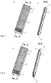
- Fig. 1
- einen ersten Schar in a) perspektivischer Draufsicht und b) im Querschnitt entlang der Schnittlinie A-A
- Fig. 2
- einen zweiten Meißel in a) perspektivischer Draufsicht und b) im Querschnitt entlang der Schnittlinie B-B
- Fig. 3
- einen dritten Schar in a) perspektivischer Draufsicht und b) im Querschnitt entlang der Schnittlinie C-C
- Fig. 1
- a first group in a) perspective plan view and b) in cross section along the section line AA
- Fig. 2
- a second bit in a) perspective plan view and b) in cross section along the section line BB
- Fig. 3
- a third group in a) perspective plan view and b) in cross section along the section line CC
Werden in den
Die in den
Erfindungsgemäß ist die in den Boden eingreifende Vorderseite des Grundkörpers 1 vollflächig mit einer hochverschleißfesten Beschichtung 3 verstärkt.According to the invention, the front face of the
In den jeweiligen Querschnittansichten b) ist gut zu erkennen, dass das Höhenniveau zwischen der Oberfläche der Voll-Hartmetallplatte 4 und der Oberfläche der-Beschichtung 3 im Wesentlichen keinen Unterschied aufweist und die Oberfläche der Beschichtung 3 als relativ glatte Oberfläche ohne Vertiefungen oder Krater ausgebildet ist.It can be clearly seen in the respective cross-sectional views b) that the height level between the surface of the
Die vollflächige Beschichtung 3 grenzt unmittelbar an die Voll-Hartmetallplatte 4 an.The full-
Zudem kann das jeweilige Schneid- und/oder Mischwerkzeug - wie vorliegend - mindestens eine Bohrung zum Einbringen eines Befestigungsteils aufweisen, um das Schneid- und/oder Mischwerkzeug an vorgegebener Stelle eines Stiels oder Grindels des landwirtschaftlichen Gerätes zu befestigen.In addition, the respective cutting and / or mixing tool - as in the present case - have at least one bore for introducing a fastening part in order to fasten the cutting and / or mixing tool at the predetermined location of a handle or grind of the agricultural implement.
Die erfindungsgemäße Beschichtung 3 ist in diesem Fall unmittelbar an die Bohrung 2 herangeführt, sondern endet wenige Millimeter vor der Bohrungskante.The
Claims (16)
- A cutting and/or mixing tool, preferably a share, for an agricultural device, in particular for a soil cultivation device, in which the cutting and/or mixing tool has a base body (1) preferably made from steel,
which, at least in the region of the tip facing the soil, is provided with at least one solid carbide chip and/or at least one solid carbide plate (4) on the front side which engages in the soil,
characterised in that the front side of the base body (1), which engages in the soil, is reinforced with a full-surface coating (3) immediately adjacent to the solid carbide chip or to the solid carbide plate (4), wherein the solid carbide surface does not have a reinforcing coating and wherein there are substantially no differences in height between the carbide surface and the coating surface. - The cutting and/or mixing tool according to Claim 1, characterised in that the full-surface coating (3) is highly resistant to wear.
- The cutting and/or mixing tool according to one of Claims 1 or 2, characterised in that the surface of the coating (3) is formed as a relatively smooth surface without depressions or craters.
- The cutting and/or mixing tool according to one of Claims 1 to 3, characterised in that the depth of roughness of the surface of the coating (3) is so slight that the material, in particular the earth, which comes into contact with the coating (3) when cultivating the soil does not settle extensively in these depressions or craters.
- The cutting and/or mixing tool according to one of Claims 1 to 4, characterised in that the full-surface coating (3) is directly adjacent to the solid carbide chip or the solid carbide plate (4) and is in contact therewith.
- The cutting and/or mixing tool according to Claim 5, characterised in that a gap which is still minimally present between the full-surface coating (3) and the carbide chip or the carbide plate (4) is filled with a material, preferably filled with that material which is provided for producing the joint between the carbide chip or the carbide plate (4) and the base body (1), preferably soldering material.
- The cutting and/or mixing tool according to one of Claims 1 to 6, characterised in that the hardness grade of the carbide chip or the carbide plate (4) is higher than the hardness grade of the full-surface coating (3) and this is in turn higher than that of the base body (1), which is preferably made from steel.
- The cutting and/or mixing tool according to one of Claims 1 to 7, characterised in that the base body (1) is cast, forged or produced from flat or sectional steel.
- The cutting and/or mixing tool according to one of Claims 1 to 8, characterised in that the coating material is a substance which is thermally applied to the surface of the base body (1).
- The cutting and/or mixing tool according to Claim 9, characterised in that the coating material is a substance which is welded onto the surface of the base body (1).
- The cutting and/or mixing tool according to one of Claims 1 to 10, characterised in that, in addition to the front side, the longitudinal sides also have a full-surface coating.
- The cutting and/or mixing tool according to one of Claims 1 to 11, characterised in that the cutting and/or mixing tool has at least one mounting part or a bore (2) for inserting a mounting part.
- The cutting and/or mixing tool according to Claim 12, characterised in that, if a bore (2) is present, the coating (3) does not lead directly up to the bore (2) but ends a few millimeters, preferably 1 to 5 millimeters, before the bore edge.
- The cutting and/or mixing tool according to one of Claims 1 to 13, characterised in that the cutting and/or mixing tool is a cultivator share.
- The cutting and/or mixing tool according to one of Claims 1 to 13, characterised in that the cutting and/or mixing tool is a cutter.
- The cutting and/or mixing tool according to one of Claims 1 to 13, characterised in that the cutting and/or mixing tool is a plough share.
Priority Applications (1)
| Application Number | Priority Date | Filing Date | Title |
|---|---|---|---|
| PL12192200T PL2591648T3 (en) | 2011-11-12 | 2012-11-12 | Cutting and/or mixing tool, in particular share, for an agricultural device, in particular for a soil cultivation device |
Applications Claiming Priority (2)
| Application Number | Priority Date | Filing Date | Title |
|---|---|---|---|
| DE102011118212 | 2011-11-12 | ||
| DE201110119629 DE102011119629A1 (en) | 2011-11-12 | 2011-11-29 | Cutting and / or mixing tool, in particular share, for an agricultural implement, in particular for a harrow |
Publications (2)
| Publication Number | Publication Date |
|---|---|
| EP2591648A1 EP2591648A1 (en) | 2013-05-15 |
| EP2591648B1 true EP2591648B1 (en) | 2018-03-21 |
Family
ID=47227541
Family Applications (1)
| Application Number | Title | Priority Date | Filing Date |
|---|---|---|---|
| EP12192200.9A Active EP2591648B1 (en) | 2011-11-12 | 2012-11-12 | Cutting and/or mixing tool, in particular share, for an agricultural device, in particular for a soil cultivation device |
Country Status (4)
| Country | Link |
|---|---|
| EP (1) | EP2591648B1 (en) |
| DE (1) | DE102011119629A1 (en) |
| DK (1) | DK2591648T3 (en) |
| PL (1) | PL2591648T3 (en) |
Families Citing this family (10)
| Publication number | Priority date | Publication date | Assignee | Title |
|---|---|---|---|---|
| CZ304675B6 (en) * | 2012-12-25 | 2014-08-27 | Farmet A.S. | Agricultural machine working implement |
| CZ305110B6 (en) * | 2012-12-26 | 2015-05-06 | Farmet A.S. | Bimetallic material |
| AT515782B1 (en) * | 2014-08-07 | 2015-12-15 | Boehlerit Gmbh & Co Kg | Tillage tool |
| DE102014115209A1 (en) | 2014-10-20 | 2016-04-21 | Amazonen-Werke H. Dreyer Gmbh & Co. Kg | Tillage tool |
| DE202015009472U1 (en) | 2014-12-22 | 2017-10-23 | Betek Gmbh & Co. Kg | Tooling system |
| CN105103677A (en) * | 2015-09-29 | 2015-12-02 | 哈尔滨市金马农机配件制造有限公司 | Novel rotary blade |
| DE102016105410A1 (en) * | 2016-03-23 | 2017-09-28 | Amazonen-Werke H. Dreyer Gmbh & Co. Kg | Agricultural plowing tool engaging in the ground |
| AT16266U1 (en) | 2018-01-29 | 2019-05-15 | Boehlerit Gmbh & Co Kg | Tillage tool |
| CN110337841A (en) * | 2019-06-30 | 2019-10-18 | 安徽省新田农业机械制造有限公司 | A kind of novel multi-use rotary blade |
| AT522699B1 (en) | 2019-07-02 | 2021-01-15 | Boehlerit Gmbh & Co Kg | Share for a tillage implement |
Family Cites Families (10)
| Publication number | Priority date | Publication date | Assignee | Title |
|---|---|---|---|---|
| DE1627793B1 (en) * | 1966-09-29 | 1971-04-15 | Takakita Akira | Method for producing a top layer |
| DE8006120U1 (en) * | 1980-03-06 | 1980-07-10 | Pflugfabrik Lemken Kg, 4234 Alpen | PLOW BODY WITH A MOLDING PLATE |
| DE8303393U1 (en) * | 1983-02-08 | 1983-12-01 | Dohrmann, geb. Verbarg, Gisela, 4992 Espelkamp | Coating of wear parts |
| DK165775C (en) * | 1985-07-18 | 1993-06-14 | Teknologisk Inst | PROCEDURE FOR MANUFACTURING A SLOT FOR A EQUIPMENT |
| US5427186A (en) | 1993-12-20 | 1995-06-27 | Caterpillar Inc. | Method for forming wear surfaces and the resulting part |
| EP0923851A1 (en) * | 1997-12-19 | 1999-06-23 | RDZ DUTZI GmbH | Loosening share for soil working implement |
| EP1346621A1 (en) * | 2002-03-22 | 2003-09-24 | Rabe Agrarsysteme GmbH & Co. KG | Soil working machine tine |
| DE10324239B4 (en) * | 2003-05-28 | 2016-01-14 | Lemken Gmbh & Co. Kg | Plow body with mouldboard |
| US6945332B2 (en) * | 2004-01-20 | 2005-09-20 | Kashiwatool Corporation | Aeration tine device |
| DE202008017715U1 (en) * | 2008-08-13 | 2010-05-27 | Zwez, Moritz | Rubber cover as wear protection for a mouldboard on a plow |
-
2011
- 2011-11-29 DE DE201110119629 patent/DE102011119629A1/en not_active Withdrawn
-
2012
- 2012-11-12 EP EP12192200.9A patent/EP2591648B1/en active Active
- 2012-11-12 PL PL12192200T patent/PL2591648T3/en unknown
- 2012-11-12 DK DK12192200.9T patent/DK2591648T3/en active
Non-Patent Citations (1)
| Title |
|---|
| None * |
Also Published As
| Publication number | Publication date |
|---|---|
| EP2591648A1 (en) | 2013-05-15 |
| DK2591648T3 (en) | 2018-06-06 |
| PL2591648T3 (en) | 2018-09-28 |
| DE102011119629A1 (en) | 2013-05-16 |
Similar Documents
| Publication | Publication Date | Title |
|---|---|---|
| EP2591648B1 (en) | Cutting and/or mixing tool, in particular share, for an agricultural device, in particular for a soil cultivation device | |
| EP3289845B1 (en) | Soil working tool | |
| EP2962538B1 (en) | Soil working tool | |
| AT521792B1 (en) | Cutting element | |
| EP3837934B1 (en) | Earth working implement for agricultural earth treatment | |
| EP3701781B1 (en) | Hard metal insert for an agricultural device | |
| EP0923851A1 (en) | Loosening share for soil working implement | |
| EP3818793A1 (en) | Cutting blade and tool combination with a cutting blade and agricultural soil working machine | |
| EP1346621A1 (en) | Soil working machine tine | |
| DE102016114447B4 (en) | Tillage tines for a tillage implement and tillage implement | |
| DE102019106393B4 (en) | Wing share tip and tillage implement with it | |
| DE202016002876U1 (en) | Soil cultivation tool for agricultural tillage machine and cutting element therefor | |
| WO2019145558A1 (en) | Soil-working tool | |
| WO2019197518A1 (en) | Soil working device | |
| EP3172951B1 (en) | Soil working tool | |
| DE202009019047U1 (en) | Tillage tool | |
| EP3235358A1 (en) | Plough point for use in a metering system for soil cultivation | |
| BE1021638B1 (en) | FIELD CHOPPER WITH FLOOR. | |
| EP4356703A1 (en) | Agricultural sweep | |
| DE202016002875U1 (en) | Soil cultivation tool for agricultural tillage machine and cutting element therefor | |
| DE202016008821U1 (en) | Tillage tines for a tillage implement and tillage implement | |
| DE202019006037U1 (en) | Wing share tip and soil tillage device with it | |
| DE102010037149A1 (en) | Meißelsäschar for direct sowing | |
| EP3225088A1 (en) | Soil working tool | |
| DE8613830U1 (en) | Plugschar |
Legal Events
| Date | Code | Title | Description |
|---|---|---|---|
| PUAI | Public reference made under article 153(3) epc to a published international application that has entered the european phase |
Free format text: ORIGINAL CODE: 0009012 |
|
| AK | Designated contracting states |
Kind code of ref document: A1 Designated state(s): AL AT BE BG CH CY CZ DE DK EE ES FI FR GB GR HR HU IE IS IT LI LT LU LV MC MK MT NL NO PL PT RO RS SE SI SK SM TR |
|
| AX | Request for extension of the european patent |
Extension state: BA ME |
|
| 17P | Request for examination filed |
Effective date: 20131108 |
|
| RBV | Designated contracting states (corrected) |
Designated state(s): AL AT BE BG CH CY CZ DE DK EE ES FI FR GB GR HR HU IE IS IT LI LT LU LV MC MK MT NL NO PL PT RO RS SE SI SK SM TR |
|
| GRAP | Despatch of communication of intention to grant a patent |
Free format text: ORIGINAL CODE: EPIDOSNIGR1 |
|
| RIC1 | Information provided on ipc code assigned before grant |
Ipc: A01B 15/04 20060101AFI20171114BHEP Ipc: A01B 33/10 20060101ALI20171114BHEP |
|
| INTG | Intention to grant announced |
Effective date: 20171211 |
|
| GRAS | Grant fee paid |
Free format text: ORIGINAL CODE: EPIDOSNIGR3 |
|
| GRAA | (expected) grant |
Free format text: ORIGINAL CODE: 0009210 |
|
| AK | Designated contracting states |
Kind code of ref document: B1 Designated state(s): AL AT BE BG CH CY CZ DE DK EE ES FI FR GB GR HR HU IE IS IT LI LT LU LV MC MK MT NL NO PL PT RO RS SE SI SK SM TR |
|
| REG | Reference to a national code |
Ref country code: GB Ref legal event code: FG4D Free format text: NOT ENGLISH |
|
| REG | Reference to a national code |
Ref country code: CH Ref legal event code: EP |
|
| REG | Reference to a national code |
Ref country code: AT Ref legal event code: REF Ref document number: 980068 Country of ref document: AT Kind code of ref document: T Effective date: 20180415 |
|
| REG | Reference to a national code |
Ref country code: IE Ref legal event code: FG4D Free format text: LANGUAGE OF EP DOCUMENT: GERMAN |
|
| REG | Reference to a national code |
Ref country code: DE Ref legal event code: R096 Ref document number: 502012012370 Country of ref document: DE |
|
| REG | Reference to a national code |
Ref country code: DK Ref legal event code: T3 Effective date: 20180529 |
|
| REG | Reference to a national code |
Ref country code: SE Ref legal event code: TRGR |
|
| REG | Reference to a national code |
Ref country code: NL Ref legal event code: MP Effective date: 20180321 |
|
| PG25 | Lapsed in a contracting state [announced via postgrant information from national office to epo] |
Ref country code: HR Free format text: LAPSE BECAUSE OF FAILURE TO SUBMIT A TRANSLATION OF THE DESCRIPTION OR TO PAY THE FEE WITHIN THE PRESCRIBED TIME-LIMIT Effective date: 20180321 Ref country code: CY Free format text: LAPSE BECAUSE OF FAILURE TO SUBMIT A TRANSLATION OF THE DESCRIPTION OR TO PAY THE FEE WITHIN THE PRESCRIBED TIME-LIMIT Effective date: 20180321 Ref country code: LT Free format text: LAPSE BECAUSE OF FAILURE TO SUBMIT A TRANSLATION OF THE DESCRIPTION OR TO PAY THE FEE WITHIN THE PRESCRIBED TIME-LIMIT Effective date: 20180321 Ref country code: NO Free format text: LAPSE BECAUSE OF FAILURE TO SUBMIT A TRANSLATION OF THE DESCRIPTION OR TO PAY THE FEE WITHIN THE PRESCRIBED TIME-LIMIT Effective date: 20180621 Ref country code: FI Free format text: LAPSE BECAUSE OF FAILURE TO SUBMIT A TRANSLATION OF THE DESCRIPTION OR TO PAY THE FEE WITHIN THE PRESCRIBED TIME-LIMIT Effective date: 20180321 |
|
| REG | Reference to a national code |
Ref country code: LT Ref legal event code: MG4D |
|
| PG25 | Lapsed in a contracting state [announced via postgrant information from national office to epo] |
Ref country code: LV Free format text: LAPSE BECAUSE OF FAILURE TO SUBMIT A TRANSLATION OF THE DESCRIPTION OR TO PAY THE FEE WITHIN THE PRESCRIBED TIME-LIMIT Effective date: 20180321 Ref country code: GR Free format text: LAPSE BECAUSE OF FAILURE TO SUBMIT A TRANSLATION OF THE DESCRIPTION OR TO PAY THE FEE WITHIN THE PRESCRIBED TIME-LIMIT Effective date: 20180622 Ref country code: BG Free format text: LAPSE BECAUSE OF FAILURE TO SUBMIT A TRANSLATION OF THE DESCRIPTION OR TO PAY THE FEE WITHIN THE PRESCRIBED TIME-LIMIT Effective date: 20180621 Ref country code: RS Free format text: LAPSE BECAUSE OF FAILURE TO SUBMIT A TRANSLATION OF THE DESCRIPTION OR TO PAY THE FEE WITHIN THE PRESCRIBED TIME-LIMIT Effective date: 20180321 |
|
| PG25 | Lapsed in a contracting state [announced via postgrant information from national office to epo] |
Ref country code: MT Free format text: LAPSE BECAUSE OF FAILURE TO SUBMIT A TRANSLATION OF THE DESCRIPTION OR TO PAY THE FEE WITHIN THE PRESCRIBED TIME-LIMIT Effective date: 20180321 |
|
| PG25 | Lapsed in a contracting state [announced via postgrant information from national office to epo] |
Ref country code: ES Free format text: LAPSE BECAUSE OF FAILURE TO SUBMIT A TRANSLATION OF THE DESCRIPTION OR TO PAY THE FEE WITHIN THE PRESCRIBED TIME-LIMIT Effective date: 20180321 Ref country code: AL Free format text: LAPSE BECAUSE OF FAILURE TO SUBMIT A TRANSLATION OF THE DESCRIPTION OR TO PAY THE FEE WITHIN THE PRESCRIBED TIME-LIMIT Effective date: 20180321 Ref country code: EE Free format text: LAPSE BECAUSE OF FAILURE TO SUBMIT A TRANSLATION OF THE DESCRIPTION OR TO PAY THE FEE WITHIN THE PRESCRIBED TIME-LIMIT Effective date: 20180321 Ref country code: NL Free format text: LAPSE BECAUSE OF FAILURE TO SUBMIT A TRANSLATION OF THE DESCRIPTION OR TO PAY THE FEE WITHIN THE PRESCRIBED TIME-LIMIT Effective date: 20180321 Ref country code: IT Free format text: LAPSE BECAUSE OF FAILURE TO SUBMIT A TRANSLATION OF THE DESCRIPTION OR TO PAY THE FEE WITHIN THE PRESCRIBED TIME-LIMIT Effective date: 20180321 Ref country code: RO Free format text: LAPSE BECAUSE OF FAILURE TO SUBMIT A TRANSLATION OF THE DESCRIPTION OR TO PAY THE FEE WITHIN THE PRESCRIBED TIME-LIMIT Effective date: 20180321 |
|
| PG25 | Lapsed in a contracting state [announced via postgrant information from national office to epo] |
Ref country code: SM Free format text: LAPSE BECAUSE OF FAILURE TO SUBMIT A TRANSLATION OF THE DESCRIPTION OR TO PAY THE FEE WITHIN THE PRESCRIBED TIME-LIMIT Effective date: 20180321 Ref country code: CZ Free format text: LAPSE BECAUSE OF FAILURE TO SUBMIT A TRANSLATION OF THE DESCRIPTION OR TO PAY THE FEE WITHIN THE PRESCRIBED TIME-LIMIT Effective date: 20180321 Ref country code: SK Free format text: LAPSE BECAUSE OF FAILURE TO SUBMIT A TRANSLATION OF THE DESCRIPTION OR TO PAY THE FEE WITHIN THE PRESCRIBED TIME-LIMIT Effective date: 20180321 |
|
| PG25 | Lapsed in a contracting state [announced via postgrant information from national office to epo] |
Ref country code: PT Free format text: LAPSE BECAUSE OF FAILURE TO SUBMIT A TRANSLATION OF THE DESCRIPTION OR TO PAY THE FEE WITHIN THE PRESCRIBED TIME-LIMIT Effective date: 20180723 |
|
| REG | Reference to a national code |
Ref country code: DE Ref legal event code: R097 Ref document number: 502012012370 Country of ref document: DE |
|
| PLBE | No opposition filed within time limit |
Free format text: ORIGINAL CODE: 0009261 |
|
| STAA | Information on the status of an ep patent application or granted ep patent |
Free format text: STATUS: NO OPPOSITION FILED WITHIN TIME LIMIT |
|
| 26N | No opposition filed |
Effective date: 20190102 |
|
| PG25 | Lapsed in a contracting state [announced via postgrant information from national office to epo] |
Ref country code: SI Free format text: LAPSE BECAUSE OF FAILURE TO SUBMIT A TRANSLATION OF THE DESCRIPTION OR TO PAY THE FEE WITHIN THE PRESCRIBED TIME-LIMIT Effective date: 20180321 |
|
| REG | Reference to a national code |
Ref country code: CH Ref legal event code: PL |
|
| GBPC | Gb: european patent ceased through non-payment of renewal fee |
Effective date: 20181112 |
|
| PG25 | Lapsed in a contracting state [announced via postgrant information from national office to epo] |
Ref country code: MC Free format text: LAPSE BECAUSE OF FAILURE TO SUBMIT A TRANSLATION OF THE DESCRIPTION OR TO PAY THE FEE WITHIN THE PRESCRIBED TIME-LIMIT Effective date: 20180321 Ref country code: LU Free format text: LAPSE BECAUSE OF NON-PAYMENT OF DUE FEES Effective date: 20181112 |
|
| REG | Reference to a national code |
Ref country code: BE Ref legal event code: MM Effective date: 20181130 |
|
| REG | Reference to a national code |
Ref country code: IE Ref legal event code: MM4A |
|
| PG25 | Lapsed in a contracting state [announced via postgrant information from national office to epo] |
Ref country code: LI Free format text: LAPSE BECAUSE OF NON-PAYMENT OF DUE FEES Effective date: 20181130 Ref country code: CH Free format text: LAPSE BECAUSE OF NON-PAYMENT OF DUE FEES Effective date: 20181130 |
|
| PG25 | Lapsed in a contracting state [announced via postgrant information from national office to epo] |
Ref country code: IE Free format text: LAPSE BECAUSE OF NON-PAYMENT OF DUE FEES Effective date: 20181112 |
|
| PG25 | Lapsed in a contracting state [announced via postgrant information from national office to epo] |
Ref country code: BE Free format text: LAPSE BECAUSE OF NON-PAYMENT OF DUE FEES Effective date: 20181130 |
|
| PG25 | Lapsed in a contracting state [announced via postgrant information from national office to epo] |
Ref country code: GB Free format text: LAPSE BECAUSE OF NON-PAYMENT OF DUE FEES Effective date: 20181112 |
|
| PG25 | Lapsed in a contracting state [announced via postgrant information from national office to epo] |
Ref country code: TR Free format text: LAPSE BECAUSE OF FAILURE TO SUBMIT A TRANSLATION OF THE DESCRIPTION OR TO PAY THE FEE WITHIN THE PRESCRIBED TIME-LIMIT Effective date: 20180321 |
|
| PG25 | Lapsed in a contracting state [announced via postgrant information from national office to epo] |
Ref country code: HU Free format text: LAPSE BECAUSE OF FAILURE TO SUBMIT A TRANSLATION OF THE DESCRIPTION OR TO PAY THE FEE WITHIN THE PRESCRIBED TIME-LIMIT; INVALID AB INITIO Effective date: 20121112 Ref country code: MK Free format text: LAPSE BECAUSE OF NON-PAYMENT OF DUE FEES Effective date: 20180321 |
|
| PG25 | Lapsed in a contracting state [announced via postgrant information from national office to epo] |
Ref country code: IS Free format text: LAPSE BECAUSE OF FAILURE TO SUBMIT A TRANSLATION OF THE DESCRIPTION OR TO PAY THE FEE WITHIN THE PRESCRIBED TIME-LIMIT Effective date: 20180721 |
|
| PGFP | Annual fee paid to national office [announced via postgrant information from national office to epo] |
Ref country code: PL Payment date: 20221102 Year of fee payment: 11 |
|
| P01 | Opt-out of the competence of the unified patent court (upc) registered |
Effective date: 20230601 |
|
| PGFP | Annual fee paid to national office [announced via postgrant information from national office to epo] |
Ref country code: SE Payment date: 20231123 Year of fee payment: 12 Ref country code: FR Payment date: 20231123 Year of fee payment: 12 Ref country code: DK Payment date: 20231122 Year of fee payment: 12 Ref country code: DE Payment date: 20231127 Year of fee payment: 12 Ref country code: AT Payment date: 20231117 Year of fee payment: 12 |
|
| PGFP | Annual fee paid to national office [announced via postgrant information from national office to epo] |
Ref country code: PL Payment date: 20231027 Year of fee payment: 12 |