EP2591346B1 - Verfahren zur korrektur des sensorsignals einer lambdasonde - Google Patents
Verfahren zur korrektur des sensorsignals einer lambdasonde Download PDFInfo
- Publication number
- EP2591346B1 EP2591346B1 EP11729101.3A EP11729101A EP2591346B1 EP 2591346 B1 EP2591346 B1 EP 2591346B1 EP 11729101 A EP11729101 A EP 11729101A EP 2591346 B1 EP2591346 B1 EP 2591346B1
- Authority
- EP
- European Patent Office
- Prior art keywords
- oscillations
- dynamic pressure
- caused
- pressure fluctuations
- frequency components
- Prior art date
- Legal status (The legal status is an assumption and is not a legal conclusion. Google has not performed a legal analysis and makes no representation as to the accuracy of the status listed.)
- Not-in-force
Links
Images


Classifications
-
- G—PHYSICS
- G01—MEASURING; TESTING
- G01N—INVESTIGATING OR ANALYSING MATERIALS BY DETERMINING THEIR CHEMICAL OR PHYSICAL PROPERTIES
- G01N27/00—Investigating or analysing materials by the use of electric, electrochemical, or magnetic means
- G01N27/26—Investigating or analysing materials by the use of electric, electrochemical, or magnetic means by investigating electrochemical variables; by using electrolysis or electrophoresis
- G01N27/403—Cells and electrode assemblies
- G01N27/406—Cells and probes with solid electrolytes
- G01N27/407—Cells and probes with solid electrolytes for investigating or analysing gases
- G01N27/41—Oxygen pumping cells
-
- F—MECHANICAL ENGINEERING; LIGHTING; HEATING; WEAPONS; BLASTING
- F02—COMBUSTION ENGINES; HOT-GAS OR COMBUSTION-PRODUCT ENGINE PLANTS
- F02D—CONTROLLING COMBUSTION ENGINES
- F02D41/00—Electrical control of supply of combustible mixture or its constituents
- F02D41/02—Circuit arrangements for generating control signals
- F02D41/14—Introducing closed-loop corrections
- F02D41/1438—Introducing closed-loop corrections using means for determining characteristics of the combustion gases; Sensors therefor
- F02D41/1493—Details
-
- F—MECHANICAL ENGINEERING; LIGHTING; HEATING; WEAPONS; BLASTING
- F02—COMBUSTION ENGINES; HOT-GAS OR COMBUSTION-PRODUCT ENGINE PLANTS
- F02D—CONTROLLING COMBUSTION ENGINES
- F02D41/00—Electrical control of supply of combustible mixture or its constituents
- F02D41/24—Electrical control of supply of combustible mixture or its constituents characterised by the use of digital means
- F02D41/26—Electrical control of supply of combustible mixture or its constituents characterised by the use of digital means using computer, e.g. microprocessor
- F02D41/28—Interface circuits
-
- G—PHYSICS
- G01—MEASURING; TESTING
- G01N—INVESTIGATING OR ANALYSING MATERIALS BY DETERMINING THEIR CHEMICAL OR PHYSICAL PROPERTIES
- G01N27/00—Investigating or analysing materials by the use of electric, electrochemical, or magnetic means
- G01N27/26—Investigating or analysing materials by the use of electric, electrochemical, or magnetic means by investigating electrochemical variables; by using electrolysis or electrophoresis
- G01N27/403—Cells and electrode assemblies
- G01N27/406—Cells and probes with solid electrolytes
- G01N27/4065—Circuit arrangements specially adapted therefor
-
- G—PHYSICS
- G01—MEASURING; TESTING
- G01N—INVESTIGATING OR ANALYSING MATERIALS BY DETERMINING THEIR CHEMICAL OR PHYSICAL PROPERTIES
- G01N27/00—Investigating or analysing materials by the use of electric, electrochemical, or magnetic means
- G01N27/26—Investigating or analysing materials by the use of electric, electrochemical, or magnetic means by investigating electrochemical variables; by using electrolysis or electrophoresis
- G01N27/416—Systems
- G01N27/417—Systems using cells, i.e. more than one cell and probes with solid electrolytes
- G01N27/4175—Calibrating or checking the analyser
-
- F—MECHANICAL ENGINEERING; LIGHTING; HEATING; WEAPONS; BLASTING
- F01—MACHINES OR ENGINES IN GENERAL; ENGINE PLANTS IN GENERAL; STEAM ENGINES
- F01N—GAS-FLOW SILENCERS OR EXHAUST APPARATUS FOR MACHINES OR ENGINES IN GENERAL; GAS-FLOW SILENCERS OR EXHAUST APPARATUS FOR INTERNAL-COMBUSTION ENGINES
- F01N2560/00—Exhaust systems with means for detecting or measuring exhaust gas components or characteristics
- F01N2560/02—Exhaust systems with means for detecting or measuring exhaust gas components or characteristics the means being an exhaust gas sensor
- F01N2560/025—Exhaust systems with means for detecting or measuring exhaust gas components or characteristics the means being an exhaust gas sensor for measuring or detecting O2, e.g. lambda sensors
-
- F—MECHANICAL ENGINEERING; LIGHTING; HEATING; WEAPONS; BLASTING
- F02—COMBUSTION ENGINES; HOT-GAS OR COMBUSTION-PRODUCT ENGINE PLANTS
- F02D—CONTROLLING COMBUSTION ENGINES
- F02D41/00—Electrical control of supply of combustible mixture or its constituents
- F02D41/02—Circuit arrangements for generating control signals
- F02D41/14—Introducing closed-loop corrections
- F02D41/1401—Introducing closed-loop corrections characterised by the control or regulation method
- F02D2041/1413—Controller structures or design
- F02D2041/1432—Controller structures or design the system including a filter, e.g. a low pass or high pass filter
-
- F—MECHANICAL ENGINEERING; LIGHTING; HEATING; WEAPONS; BLASTING
- F02—COMBUSTION ENGINES; HOT-GAS OR COMBUSTION-PRODUCT ENGINE PLANTS
- F02D—CONTROLLING COMBUSTION ENGINES
- F02D41/00—Electrical control of supply of combustible mixture or its constituents
- F02D41/24—Electrical control of supply of combustible mixture or its constituents characterised by the use of digital means
- F02D41/26—Electrical control of supply of combustible mixture or its constituents characterised by the use of digital means using computer, e.g. microprocessor
- F02D41/28—Interface circuits
- F02D2041/286—Interface circuits comprising means for signal processing
- F02D2041/288—Interface circuits comprising means for signal processing for performing a transformation into the frequency domain, e.g. Fourier transformation
-
- G—PHYSICS
- G01—MEASURING; TESTING
- G01N—INVESTIGATING OR ANALYSING MATERIALS BY DETERMINING THEIR CHEMICAL OR PHYSICAL PROPERTIES
- G01N27/00—Investigating or analysing materials by the use of electric, electrochemical, or magnetic means
- G01N27/26—Investigating or analysing materials by the use of electric, electrochemical, or magnetic means by investigating electrochemical variables; by using electrolysis or electrophoresis
- G01N27/416—Systems
- G01N27/417—Systems using cells, i.e. more than one cell and probes with solid electrolytes
- G01N27/419—Measuring voltages or currents with a combination of oxygen pumping cells and oxygen concentration cells
Definitions
- the present invention relates to a method for operating a sensor element, in particular a broadband lambda probe according to the preamble of claim 1.
- lambda sensors are used to determine the air ratio, which describes the ratio of air to fuel. This ratio is of crucial importance for the combustion of the fuel in an internal combustion engine and for the exhaust aftertreatment.
- jump probes and broadband probes are known.
- a jumping probe the potential of an exhaust gas-side electrode is measured relative to an oxygen-purged reference electrode.
- a jumping probe can detect the transition from a rich to a lean mixture and vice versa.
- a broadband lambda probe can measure the residual oxygen content in the exhaust over a much wider range, ie both rich and lean. It essentially consists of a combination of a conventional concentration probe acting as a galvanic cell (Nernst probe) and a limiting current or "pump" cell. A voltage is applied to the pump cell from the outside. When the voltage is high enough, a threshold current is established which is proportional to the difference in oxygen concentration on both sides of the cell.
- the respective pumping current which is proportional to the oxygen or fat gas content in the exhaust gas, forms the output signal of the broadband lambda probe.
- the measurement of the concentration in the sample gas space is based on the determination of the Nernst voltage between a Nernst electrode in the sample gas space and an oxygen-purged reference electrode in a reference space.
- a broadband lambda probe is equipped with an integrated heater.
- the measuring signal of the lambda probe is dependent both on the air ratio ⁇ , ie the ratio of air to fuel in the mixture, and on the prevailing absolute pressure.
- ⁇ the absolute pressure of the exhaust gas fluctuates by several 100 mbar.
- the occurring oscillations of the pumping current can be smoothed by a suitable electronic filtering. Overall, however, there is a shift in the mean pumping current, which is associated with a loss of a characteristic accuracy.
- the invention is based on the object to provide a method for operating a sensor element, in particular a broadband lambda probe, which allows reliable compensation of the dynamic pressure dependence of the pumping current and thus increases the measurement accuracy of the sensor element.
- the method should also be able to be used with existing sensor elements without having to make any further changes to the sensor element itself.
- the method according to the invention is provided for operating a sensor element, in particular a lambda probe, which is suitable for determining the concentration of a gas component in a gas mixture.
- the gas component is removed by applying a pumping voltage from the sample gas space and from this it is concluded that the concentration of the gas component in the gas mixture.
- such sensor elements may be broadband lambda probes which function according to the so-called two-line principle or the so-called single-cell principle.
- the concentration of the gas component in the measurement gas space is adjusted to a predefinable value and closed from the measured pumping current to the concentration of the gas component in the gas mixture.
- the concentration of the gas component can be measured by means of a limiting current.
- the method according to the invention is characterized characterized in that oscillations of the pumping current, which are caused by dynamic pressure fluctuations, are taken into account for a correction of the pumping current.
- Dynamic pressure fluctuations that arise, for example, with the frequency of the cylinder ignition of the internal combustion engine, ultimately affect the pumping current and thus the measurement signal of the sensor element.
- the core of the invention is to identify these generated by dynamic pressure fluctuations oscillations or their frequency components and to correct the probe signal accordingly. As a result, the specific mean value shift of the pumping current, which is caused by the pressure oscillations, can be compensated, whereby the measuring accuracy of the sensor element is significantly improved.
- the oscillations of the pumping current are analyzed to identify the frequency components caused by the dynamic pressure fluctuations.
- the pumping current is corrected by the frequency components caused by the dynamic pressure fluctuations.
- These frequency components are also referred to below as frequency components of the pressure fluctuations.
- the identification of the frequency components of the pressure fluctuations and their compensation can be carried out with particular advantage as a function of a software of the operating electronics. There are no further adjustments of the sensor element itself required. Rather, the inventive method can be used by adjusting or supplementing the evaluation software of a sensor element, so that the inventive method can also be used in existing sensor elements.
- the analysis of the oscillations is performed by a frequency analysis.
- the oscillations which are caused by variations in the ratio of air to fuel or lambda fluctuations, have a lower frequency than the oscillations caused by dynamic pressure fluctuations. Because of these differences, the lambda oscillations can be separated from the pressure oscillations, so that the frequency components of the pressure fluctuations can be identified and considered according to the invention for a correction.
- the analysis of the frequencies by a Fourier frequency analysis, ie a decomposition of the oscillations in their different sine and cosine functions, so as to differentiate the frequency components, which go back to the lambda oscillations on the one hand and on the other hand, the dynamic pressure oscillations oscillations.
- the frequency components which are caused by the dynamic pressure fluctuations can be subtracted from the oscillations of the pumping current so that ultimately only the lambda oscillations come into play in the evaluation of the measuring signal of the sensor element.
- the correction of the sensor signal can take place with the aid of a characteristic diagram.
- the shift of the mean pumping current as a result of the oscillations or oscillation components of the pumping current caused by dynamic pressure changes is characterized by a so-called specific mean value shift.
- This specific mean shift depends on the type of probe as well as the frequency of the pressure fluctuations and the prevailing mean pressure. The shape and amplitude of the pressure pulses have no influence on this size.
- the specific mean value shift can thus be assigned to a current operating point-dependent combination of amplitude, frequency and form factor of a probe-typical displacement of the average pump current. This relationship can be stored for example in the form of a map in an evaluation and / or control unit.
- the shift of the mean pumping current is then calculated from the current operating point-dependent combination of pressure pulse amplitude and shape and from the specific mean value shift taken from the characteristic diagram.
- the measured pumping current or the sensor signal and the associated error in the lambda measurement can be shifted or corrected in order to compensate for the specific mean value shift as a result of the dynamic pressure dependence of the pumping current.
- It is possible to determine the amplitude and the shape factor of the pressure pulses as a function of the operating point for example also by means of a characteristic map or, in a particularly preferred manner, by means of a dynamic pressure model.
- Such pressure models are the expert, for example, in connection with the compensation of the static pressure dependence of Probe signal in a similar manner known.
- the frequency of the pressure pulses can be derived, for example, from the engine speed.
- the frequency components of the oscillations caused by dynamic pressure fluctuations can be characterized by at least one quantity which is assigned to a sensor element-typical mean value shift of the pumping current, for example in the form of a characteristic diagram. Based on this assignment, the correction of the pump current can be made.
- the relationship between the frequency components caused by dynamic pressure fluctuations and operating parameters or operating conditions that are measurable or derivable can be summarized using a dynamic pressure model, so that the oscillations of the pumping current or its pressure fluctuation frequency components caused by dynamic pressure fluctuations one or more operating variables can be determined in order to be considered according to the invention for the correction of the sensor signal can.
- only low frequencies are distinguished from high frequencies in the analysis of the oscillations of the pump current.
- Low frequencies are preferably those below 25 Hz
- high frequencies are preferably those above 25 Hz.
- This simplified frequency analysis for example in the form of a (fast) Fourier transformation, can be carried out with little effort and still achieves very advantageous results.
- the signal of the sensor by a Passed high pass filter and rectified. The averaged amplitude is then used as a parameter for the sensor signal correction.
- the shift of the average pumping current that occurs due to the pressure pulses should be considered in this embodiment.
- the shape, amplitude and frequency of the pressure pulses change relatively slowly compared to their period.
- the fat-lean oscillations of the mixture control as well as changes in the air characteristic due to load changes typically occur at frequencies of only about 10 Hz. These relatively slow changes therefore allow a sufficiently fast compensation according to the invention in adaptation to a new operating point.
- interference signals can be taken into account in the correction of the pumping current.
- the interference signal can be determined, for example, from the steepness of the pumping current change on the basis of a characteristic map stored in the software and subtracted from the measured pumping current.
- the interference signal of the pumping current due to a crosstalk of the heater timing of the sensor element can be considered according to the invention.
- This interference signal can be determined, for example, from the heating power, the control signals, in particular the duty cycle of the heater, and the heater and optionally the engine operating point, the exhaust gas temperature, etc. based on a map stored in the software and subtracted from the measured pumping current.
- a corresponding characteristic map can be recalibrated in suitable operating phases by measuring and storing the unfiltered and uncompensated interference signal of the pumping current at the heater input.
- the invention further comprises a computer program that performs all the steps of the method according to the invention when it runs on a computing device or a control unit.
- the invention includes a computer program product with program code, which is stored on a machine-readable carrier, for carrying out the method according to the invention, when the program is executed on a computer or a control unit.
- the method according to the invention can also be used without difficulty in existing sensor elements and used there to compensate for oscillations or oscillation components of the pumping current which are caused by dynamic pressure fluctuations.
- the specific mean value shift can be compensated according to the invention by correcting the pump current by the frequency components caused by the pressure fluctuations.
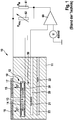
- FIG. 1 shows a known from the prior art broadband lambda probe, which is provided for determining the oxygen concentration in a gas mixture, in particular in the exhaust gas of an internal combustion engine.
- the sensor element comprises a planar sensor body 10, which is formed from a solid electrolyte 11 and in which an example, annular cavity 12 is formed as a measuring gas space.
- the cavity 12 is above a central opening 13 with the exhaust gas in communication.
- a porous diffusion barrier 14 is arranged.
- an outer pumping electrode 15 is arranged, which is covered by a porous protective layer 16.
- an inner pumping electrode 17 is arranged on the side facing away from the outer pumping electrode 15.
- the outer pumping electrode 15 and the inner pumping electrode 17 define a pumping cell 18, which is provided for the transport of oxygen ions.
- a reference electrode 21 is provided within a reference gas volume 20 .
- the Nernst electrode 30 and the reference electrode 21 together form a Nernst or concentration cell 50.
- a heater 22 is arranged in a heater insulation layer 23 below the measurement gas space 12 and the reference gas volume 20.
- the heater 22 may be formed, for example, meandering.
- the heater 22 ensures a sufficient operating temperature of the sensor element 10.
- a measuring and evaluation circuit of the sensor element 10 comprises a differential amplifier 60, to whose one input a reference voltage is applied, in particular 450 mV. The other input is connected to the reference electrode 21. Further, a current divider consisting provided from a measuring resistor R M 61 and a trim resistor R Abg 62, which leads the output of the differential amplifier 60 to the outer pumping electrode 15 °.
- a pumping voltage is applied, by means of which a constant oxygen partial pressure is set in the measuring gas chamber 12 by pumping or pumping oxygen.
- the pumping voltage is regulated in such a way that a constant voltage value of, for example, 450 mV is established at the electrodes 30 and 21 of the concentration cell 50.
- This air ratio in the sample gas chamber is specified by the predeterminable reference voltage for the Nernst cell, in this case 450 mV.
- the measurable signal depends on the one hand on the air concentration in the exhaust gas mixture, ie on the air ratio of the gas mixture from.
- the measuring signal is also influenced by the absolute pressure.
- the problem here is that the absolute pressure of the exhaust gas is subject to fluctuations.
- the absolute pressure oscillates with the frequency of the cylinder ignition by several 100 mbar. With each pressure pulse, there is a brief sharp increase in the lean or rich gas components of the exhaust gas introduced into the sample gas chamber 12.
- the frequency components which are caused by the dynamic pressure fluctuations, compensated for a correction of the sensor signal, so that the caused by the pressure pulses shift of the average pumping current is adjusted.
- the oscillations are preferably analyzed. For example, for this purpose, a Fourier frequency analysis can be performed, in which the periodic signals of the pumping current are decomposed into their individual frequency components. These frequency components can be subtracted, for example, from the measured pumping current.
- the current, operating point-dependent combination of amplitude, frequency and shape factor of the pressure fluctuations of a probe-typical shift of the average pumping current is assigned in a map for the specific mean value shift, so based on this map alone by measuring the current pumping current and taking into account the respective operating point the specific mean value shift can be determined and the lambda measurement can be corrected accordingly.
- a dynamic pressure model can be used for this purpose.
- the frequency of the pressure pulses results from the engine speed.
- the method according to the invention is applied to engines whose cylinder equalization is already ensured from smoothness or other processes.
- the pump current signal contains substantially no high frequency components that would be generated by lambda differences. Rather, only fluctuations due to the pressure pulses are to be expected in the high frequency range.
- the fluctuations below a certain frequency threshold for example below 25 Hz, are caused by actual lambda fluctuations.
- the oscillations are in principle caused by pressure pulses. To a certain extent, oscillations occur above 25 Hz due to lambda fluctuations.
- These lambda fluctuations are caused by cylinder misalignments. Since they occur in principle at half the frequency of the pressure pulses, they can do well in the frequency spectrum of these be differentiated.
- the fluctuations above the certain threshold eg 25 Hz
- the frequency spectrum of the lambda fluctuations becomes wider, so that the spurs of this spectrum can also contribute above this threshold.
- these extensions are shallower than the contributions of the pressure pulses and can thus be distinguished from these.
- the Fourier amplitude which is in particular to be assigned twice the engine speed evaluated, since it can be reliably assigned to the pressure fluctuations.
- FIG. 2A shows in a schematic way the time course of the probe signal at superimposed pressure pulses and gas changes (lambda change).
- FIG. 2B shows the corresponding Fourier decomposition (FT [probe signal]).
- the course of the signal denoted 100 in FIG. 2B shows the real part (FT [Ip]) of the probe signal.
- the curve labeled 200 shows the imaginary part (FT [Ip]) of the probe signal.
- the area designated 300 indicates the static pumping current Ip.
- the signals in the Fourier spectrum above the static Ip 300 are assigned to a gas exchange or lambda change, here designated 400. Signals in the Fourier spectrum above these frequencies are to be assigned to pressure pulses, here designated 500.
- the influence of the pressure pulses can thus be separated from the actual lambda signal.
- the shift of the average pump current which causes an additional contribution at the frequency 0 Hz, should also be corrected for this.
Landscapes
- Engineering & Computer Science (AREA)
- Chemical & Material Sciences (AREA)
- Health & Medical Sciences (AREA)
- Life Sciences & Earth Sciences (AREA)
- General Physics & Mathematics (AREA)
- Immunology (AREA)
- Physics & Mathematics (AREA)
- Analytical Chemistry (AREA)
- Biochemistry (AREA)
- General Health & Medical Sciences (AREA)
- Chemical Kinetics & Catalysis (AREA)
- Electrochemistry (AREA)
- Pathology (AREA)
- Molecular Biology (AREA)
- Combustion & Propulsion (AREA)
- Mechanical Engineering (AREA)
- General Engineering & Computer Science (AREA)
- Computer Hardware Design (AREA)
- Microelectronics & Electronic Packaging (AREA)
- Combined Controls Of Internal Combustion Engines (AREA)
Description
- Die vorliegende Erfindung betrifft ein Verfahren zum Betreiben eines Sensorelements, insbesondere einer Breitbandlambdasonde gemäß dem Oberbegriff des Anspruchs 1.
- Es sind verschiedene Sensorelemente zur Bestimmung der Konzentration einer Gaskomponente in Gasgemischen bekannt. So werden beispielsweise sogenannte Lambdasonden eingesetzt, um die Luftzahl zu bestimmen, die das Verhältnis von Luft zu Kraftstoff beschreibt. Dieses Verhältnis ist für die Verbrennung des Kraftstoffs in einer Brennkraftmaschine sowie für die Abgasnachbehandlung von entscheidender Bedeutung.
- Für die Messung des Restsauerstoffgehalts im Abgas sind im Prinzip Sprungsonden und Breitbandsonden bekannt. Bei einer Sprungsonde wird das Potential einer abgasseitigen Elektrode relativ zu einer sauerstoffbespülten Referenzelektrode gemessen. Eine Sprungsonde kann den Übergang von einem fetten zu einem mageren Gemisch und umgekehrt erkennen. Eine Breitbandlambdasonde kann den Restsauerstoffgehalt im Abgas über einen wesentlich breiteren Bereich, also sowohl im fetten als auch im mageren Bereich, messen. Sie besteht im Wesentlichen aus einer Kombination einer herkömmlichen, als galvanische Zelle wirkenden Konzentrationssonde (Nernst-Sonde) sowie einer Grenzstrom- oder "Pump"-zelle. An die Pumpzelle wird von außen eine Spannung angelegt. Ist die Spannung groß genug, stellt sich ein Grenzstrom ein, der proportional zum Unterschied der Sauerstoffkonzentration auf beiden Seiten der Zelle ist. Polaritätsabhängig werden mit dem Strom Sauerstoffatome transportiert. Durch eine elektronische Regelschaltung wird der Konzentrationssonde von der Pumpzelle immer genau so viel Sauerstoff aus dem Abgas zugeführt, dass der Zustand λ = 1 herrscht. Der jeweilige Pumpstrom, der proportional zum Sauerstoff- oder Fettgasgehalt im Abgas ist, bildet das Ausgangssignal der Breitbandlambdasonde. Die Messung der Konzentration im Messgasraum erfolgt anhand der Bestimmung der Nernstspannung zwischen einer Nernstelektrode im Messgasraum und einer sauerstoffbespülten Referenzelektrode in einem Referenzraum. Um die für den Sauerstoffionentransport erforderliche Betriebstemperatur zu erreichen, ist eine Breitbandlambdasonde mit einer integrierten Heizeinrichtung ausgestattet.
- Das Messsignal der Lambdasonde ist sowohl von der Luftkennzahl λ, also dem Verhältnis von Luft zu Kraftstoff im Gemisch, als auch vom herrschenden Absolutdruck abhängig. Mit der Frequenz der Zylinderzündung der Brennkraftmaschine schwankt der Absolutdruck des Abgases um mehrere 100 mbar. Mit jedem Druckpuls wird die in den Messgasraum der Lambdasonde eintransportierte Menge an Mager- oder Fettgaskomponenten kurzzeitig stark erhöht und anschließend wieder stark abgesenkt. Da der Regler des Pumpstroms sehr schnell reagiert, kann er in der Eintransportphase die zusätzlichen Gaskomponenten, die ein Abweichen von der Soll-Konzentration im Hohlraum von λ = 1 darstellen, schnell abpumpen. Deshalb werden in der anschließenden Niederdruckphase weniger Gaskomponenten heraustransportiert, als während der Hochdruckphase eintransportiert wurden. Die auftretenden Oszillationen des Pumpstroms lassen sich durch eine geeignete elektronische Filterung glätten. Insgesamt kommt es jedoch zu einer Verschiebung des mittleren Pumpstroms, der mit einem Verlust einer Kennlinien-Genauigkeit einhergeht.
- Ein Ansatz, die hiermit einhergehende Ungenauigkeit zu minimieren, verwendet eine möglichst dichte Ausführung der Diffusionsbarrieren, die das Abgas von dem Messgasraum trennen. Allerdings wird hierdurch die statische Druckabhängigkeit der Lambdasonde erhöht. Eine andere Maßnahme zur Verminderung der Auswirkungen der dynamischen Druckabhängigkeit ist die Verkleinerung des Volumens des Messgasraums im Vergleich mit dem Volumen der Diffusionsbarriere, wie es beispielsweise aus der Offenlegungsschrift
DE 10 2004 023 004 A1 hervorgeht. Auch hierdurch lässt sich die Abhängigkeit des Messsignals von den dynamischen Druckschwankungen vermindern. Die Verkleinerung des Messgasraums kann jedoch andere Nachteile mit sich bringen. Wegen des hohen Diffusionswiderstandes des Hohlraums wird der Sauerstoff hierbei nur an der Vorderkante der Elektrode abgepumpt und dadurch die Elektrode lokal überlastet. Dies gilt insbesondere für Vergiftungen durch antransportierte gasförmige Elektrodengifte. - Der Erfindung liegt demgegenüber die Aufgabe zugrunde, ein Verfahren zum Betreiben eines Sensorelements, insbesondere einer Breitbandlambdasonde bereitzustellen, das eine zuverlässige Kompensation der dynamischen Druckabhängigkeit des Pumpstroms erlaubt und damit die Messgenauigkeit des Sensorelements erhöht. Das Verfahren soll auch bei bestehenden Sensorelementen eingesetzt werden können, ohne dass weitere Veränderungen an dem Sensorelement selbst vorgenommen werden müssen.
- Diese Aufgabe wird durch ein Verfahren gelöst, wie es Gegenstand des Anspruchs 1 ist. Bevorzugte Ausgestaltungen des erfindungsgemäßen Verfahrens ergeben sich aus den Unteransprüchen.
- Das erfindungsgemäße Verfahren ist zum Betreiben eines Sensorelements, insbesondere einer Lambdasonde vorgesehen, die zur Bestimmung der Konzentration einer Gaskomponente in einem Gasgemisch geeignet ist. Die Gaskomponente wird durch Anlegen einer Pumpspannung aus dem Messgasraum entfernt und hieraus wird auf die Konzentration der Gaskomponente in dem Gasgemisch geschlossen. Bei derartigen Sensorelementen kann es sich insbesondere um Breitbandlambdasonden handeln, die nach dem sogenannten Zweizeiler-Prinzip oder nach dem sogenannten Einzeller-Prinzip funktionieren. Gemäß dem Zweizeiler-Prinzip wird die Konzentration der Gaskomponente in dem Messgasraum auf einen vorgebbaren Wert eingeregelt und aus dem dabei gemessenen Pumpstrom auf die Konzentration der Gaskomponente in dem Gasgemisch geschlossen. Bei einem Einzeller ist die Konzentration der Gaskomponente anhand eines Grenzstroms messbar. Das erfindungsgemäße Verfahren ist dadurch gekennzeichnet, dass Oszillationen des Pumpstroms, die durch dynamische Druckschwankungen verursacht werden, für eine Korrektur des Pumpstroms berücksichtigt werden. Dynamische Druckschwankungen, die beispielsweise mit der Frequenz der Zylinderzündung der Brennkraftmaschine entstehen, beeinflussen letztendlich den Pumpstrom und damit das Messsignal des Sensorelements. Der Kern der Erfindung liegt darin, diese durch dynamische Druckschwankungen erzeugten Oszillationen bzw. deren Frequenzanteile zu identifizieren und das Sondensignal entsprechend zu korrigieren. Hierdurch kann die spezifische Mittelwertverschiebung des Pumpstroms, die durch die Druck-Oszillationen verursacht wird, kompensiert werden, wodurch die Messgenauigkeit des Sensorelements deutlich verbessert wird.
- Vorzugsweise werden die Oszillationen des Pumpstroms analysiert, um die Frequenzanteile, die durch die dynamischen Druckschwankungen verursacht sind, zu identifizieren. Der Pumpstrom wird um die Frequenzanteile, die durch die dynamischen Druckschwankungen verursacht sind, korrigiert. Diese Frequenzanteile werden im Folgenden auch als Frequenzanteile der Druckschwankungen bezeichnet. Die Identifizierung der Frequenzanteile der Druckschwankungen und deren Kompensation kann mit besonderem Vorteil als eine Funktion einer Software der Betriebselektronik durchgeführt werden. Es sind keine weiteren Anpassungen des Sensorelements selbst erforderlich. Vielmehr kann das erfindungsgemäße Verfahren durch Anpassung oder Ergänzung der Auswertesoftware eines Sensorelements eingesetzt werden, sodass das erfindungsgemäße Verfahren auch bei bestehenden Sensorelementen verwendet werden kann.
- Mit besonderem Vorteil wird die Analyse der Oszillationen durch eine Frequenz-Analyse vorgenommen. Die Oszillationen, die durch Schwankungen im Verhältnis von Luft zu Kraftstoff bzw. durch Lambdaschwankungen verursacht werden, weisen eine kleinere Frequenz auf als die Oszillationen, die durch dynamische Druckschwankungen verursacht sind. Aufgrund dieser Unterschiede lassen sich die Lambda-Oszillationen von den Druck-Oszillationen trennen, sodass die Frequenzanteile der Druckschwankungen identifiziert und erfindungsgemäß für eine Korrektur berücksichtigt werden können. In einer besonders bevorzugten Ausführungsform erfolgt die Analyse der Frequenzen durch eine Fourier-Frequenz-Analyse, also einer Zerlegung der Oszillationen in deren verschiedene Sinus- und Cosinusfunktionen, um so die Frequenzanteile zu differenzieren, die zum einen auf die Lambda-Oszillationen und zum anderen auf die dynamischen Druckschwankungs-Oszillationen zurückgehen.
- Für die Korrektur des Sondensignals gemäß der Erfindung können die Frequenzanteile, die durch die dynamischen Druckschwankungen verursacht sind, von den Oszillationen des Pumpstroms abgezogen werden, sodass letztendlich nur die Lambda-Oszillationen bei der Auswertung des Messsignals des Sensorelements zum Tragen kommen.
- In einer anderen bevorzugten Ausgestaltung des erfindungsgemäßen Verfahrens kann die Korrektur des Sensorsignals mithilfe eines Kennfeldes erfolgen. Die eingangs beschriebene Verschiebung des mittleren Pumpstroms in Folge der durch dynamische Druckänderungen verursachten Oszillationen bzw. Oszillationsanteilen des Pumpstroms wird durch eine sogenannte spezifische Mittelwertverschiebung charakterisiert. Diese spezifische Mittelwertverschiebung hängt sowohl vom Sondentyp als auch von der Frequenz der Druckschwankungen und von dem herrschenden mittleren Druck ab. Die Form und Amplitude der Druckpulse hat auf diese Größe keinen Einfluss. Die spezifische Mittelwertverschiebung kann damit einer aktuellen, betriebspunktabhängigen Kombination aus Amplitude, Frequenz und Formfaktor einer sondentypischen Verschiebung des mittleren Pumpstroms zugeordnet werden. Dieser Zusammenhang kann beispielsweise in Form eines Kennfelds in einer Auswerte- und/oder Steuereinheit hinterlegt werden. Die Verschiebung des mittleren Pumpstroms errechnet sich dann aus der aktuellen, betriebspunktabhängigen Kombination von Druckpulsamplitude und -form sowie aus der aus dem Kennfeld entnommenen spezifischen Mittelwertverschiebung. Anhand dieses Kennfelds kann der gemessene Pumpstrom bzw. das Sensorsignal und der damit verbundene Fehler in der Lambdamessung verschoben bzw. korrigiert werden, um die spezifische Mittelwertverschiebung in Folge der dynamischen Druckabhängigkeit des Pumpstroms zu kompensieren. Es ist möglich, die Amplitude und den Formfaktor der Druckpulse in Abhängigkeit von dem Betriebspunkt zum Beispiel auch mithilfe eines Kennfelds oder in besonders bevorzugter Weise mittels eines dynamischen Druckmodells zu bestimmen. Derartige Druckmodelle sind dem Fachmann beispielsweise in Zusammenhang mit der Kompensation der statischen Druckabhängigkeit des Sondensignals in ähnlicher Weise bekannt. Die Frequenz der Druckpulse kann hierbei beispielsweise aus der Motordrehzahl abgeleitet werden. Zusammenfassend können also die Frequenzanteile der durch dynamische Druckschwankungen verursachten Oszillationen durch wenigstens eine Größe charakterisiert werden, die einer sensorelementtypischen Mittelwertverschiebung des Pumpstroms beispielsweise in Form eines Kennfeldes zugeordnet werden. Anhand dieser Zuordnung kann die Korrektur des Pumpstroms vorgenommen werden. In anderen Ausführungsformen kann der Zusammenhang zwischen den Frequenzanteilen, die durch dynamische Druckschwankungen verursacht werden, und Betriebsgrößen oder Betriebsbedingungen, die messbar oder ableitbar sind, mithilfe eines dynamischen Druckmodells zusammengefasst werden, sodass die durch dynamische Druckschwankungen verursachten Oszillationen des Pumpstroms bzw. dessen druckschwankungsbedingte Frequenzanteile anhand einer oder mehrere Betriebsgrößen ermittelt werden können, um erfindungsgemäß für die Korrektur des Sensorsignals berücksichtigt werden zu können.
- Mit Vorteil werden für die Korrektur des Sensorsignals nur solche durch dynamische Druckschwankungen verursachten Frequenzanteile berücksichtigt, deren Frequenzen oberhalb einer vorgebbaren Schwelle liegen. Da bei kleinen Frequenzen die Druckpulse im Betrag klein sind, kann es im Sinne einer vereinfachten Ausführung für das erfindungsgemäße Kompensationsverfahren ausreichend sein, nur die hohen Frequenzen auszuwerten. Insbesondere bei den hohen Frequenzen ist der Beitrag zur Mittelwertverschiebung zum Messsignal besonders relevant. Diese Ausführungsform des erfindungsgemäßen Verfahrens ist weniger aufwendig als die Berücksichtigung aller Frequenzen und kann dennoch die Messgenauigkeit des Sensorelements erheblich verbessern.
- In einer besonders bevorzugten Ausführungsform des erfindungsgemäßen Verfahrens werden bei der Analyse der Oszillationen des Pumpstroms ausschließlich niedrige Frequenzen von hohen Frequenzen unterschieden. Niedrige Frequenzen sind bevorzugt solche unterhalb von 25 Hz, hohe Frequenzen sind bevorzugt solche oberhalb von 25 Hz. Diese vereinfachte Frequenzanalyse, beispielsweise in Form einer (Fast-)Fourier-Transformation, ist mit wenig Aufwand durchführbar und erzielt dennoch sehr vorteilhafte Ergebnisse. Hierbei kann beispielsweise das Signal des Sensors durch einen Hochpassfilter geleitet und gleichgerichtet werden. Die gemittelte Amplitude wird dann als Parameter für die Sensorsignal-Korrektur verwendet. Zusätzlich sollte die Verschiebung des mittleren Pumpstroms, die infolge der Druckpulse auftritt, bei dieser Ausführungsform berücksichtigt werden.
- Die Form, Amplitude und Frequenz der Druckpulse ändern sich im Vergleich zu ihrer Periodendauer relativ langsam. Auch die Fett-Mager-Oszillationen der Gemischregelung sowie Änderungen der Luftkennzahl aufgrund von Lastwechseln treten typischerweise mit Frequenzen von etwa nur 10 Hz auf. Diese relativ langsamen Änderungen erlauben daher eine hinreichend schnelle Kompensation gemäß der Erfindung in Anpassung an einen neuen Betriebspunkt.
- Erfindungsgemäß können auch weitere Störsignale bei der Korrektur des Pumpstroms berücksichtigt werden. Insbesondere kann das Störsignal des Pumpstroms aufgrund des Durchgangs der Abgaskonzentration bein λ = 1 zusätzlich kompensiert werden. Während des Durchgangs der Abgaskonzentration durchs λ = 1 kann beispielsweise aus der Steilheit der Pumpstromänderung anhand eines in der Software hinterlegten Kennfeldes das Störsignal ermittelt und vom gemessenen Pumpstrom subtrahiert werden. Auch das Störsignal des Pumpstroms aufgrund eines Übersprechens der Heizertaktung des Sensorelements kann erfindungsgemäß berücksichtigt werden. Dieses Störsignal kann beispielsweise aus der Heizleistung, den Ansteuersignalen, insbesondere dem Duty-Cycle des Heizers, und dem Heißwiderstand des Heizers sowie gegebenenfalls dem Motorbetriebspunkt, der Abgastemperatur etc. anhand eines in der Software hinterlegten Kennfeldes ermittelt und vom gemessenen Pumpstrom subtrahiert werden. Ein entsprechendes Kennfeld kann in geeigneten Betriebsphasen neu kalibriert werden, indem das ungefilterte und unkompensierte Störsignal des Pumpstroms bei der Heizereinkopplung gemessen und gespeichert wird.
- Die Erfindung umfasst weiterhin ein Computerprogramm, das alle Schritte des erfindungsgemäßen Verfahrens ausführt, wenn es auf einem Rechengerät oder einem Steuergerät abläuft. Schließlich umfasst die Erfindung ein Computerprogrammprodukt mit Programmcode, der auf einem maschinenlesbaren Träger gespeichert ist, zur Durchführung des erfindungsgemäßen Verfahrens, wenn das Programm auf einem Computer oder einem Steuergerät ausgeführt wird. Mithilfe des Computerprogramms bzw. des Computerprogrammproduktes kann das erfindungsgemäße Verfahren ohne weiteres auch bei bestehenden Sensorelementen eingesetzt werden und dort zur Kompensation von Oszillationen bzw. Oszillationsanteilen des Pumpstroms, die durch dynamische Druckschwankungen verursacht werden, genutzt werden. Dynamische Druckschwankungen, die aufgrund eines schwankenden Absolutdrucks des Messgases insbesondere in Folge der Frequenz der Zylinderzündung entstehen, verfälschen das Messsignal eines Sensorelements, insbesondere einer Breitbandlambdasonde, wobei es zu einer Verschiebung des mittleren Pumpstroms (spezifische Mittelwertverschiebung) kommt. Die spezifische Mittelwertverschiebung kann erfindungsgemäß kompensiert werden, indem der Pumpstrom um die Frequenzanteile, die durch die Druckschwankungen verursacht werden, korrigiert wird.
- Weitere Merkmale und Vorteile der Erfindung ergeben sich aus der nachfolgenden Beschreibung von Ausführungsbeispielen im Zusammenhang mit den Zeichnungen. Hierbei können die verschiedenen Merkmale jeweils für sich oder in Kombination miteinander verwirklicht sein.
- Die Zeichnungen zeigen:
- Figur 1
- eine aus dem Stand der Technik bekannte Breitbandlambdasonde und
- Figur 2
- eine schematische Darstellung des Sondensignals bei überlagerten Druckpulsen und Gaswechseln (
Figur 2A ) und ein Fourierspektrum des Sondensignals (Figur 2B ). -
Figur 1 zeigt eine aus dem Stand der Technik bekannte Breitbandlambdasonde, die zur Bestimmung der Sauerstoffkonzentration in einem Gasgemisch, insbesondere im Abgas einer Brennkraftmaschine, vorgesehen ist. Das Sensorelement umfasst einen planaren Sensorkörper 10, der aus einem Festelektrolyten 11 gebildet ist und in dem ein beispielsweise ringförmiger Hohlraum 12 als Messgasraum ausgebildet ist. Der Hohlraum 12 steht über eine zentrale Öffnung 13 mit dem Abgas in Verbindung. Zwischen der zentralen Öffnung 13 und dem Hohlraum 12 ist eine poröse Diffusionsbarriere 14 angeordnet. Auf der Seite der Öffnung 13 ist eine Außenpumpelektrode 15 angeordnet, die von einer porösen Schutzschicht 16 überdeckt ist. Auf der Seite des Messgasraums 12 ist auf der der Außenpumpelektrode 15 abgewandten Seite eine innere Pumpelektrode 17 angeordnet. Die Außenpumpelektrode 15 und die innere Pumpelektrode 17 umgrenzen eine Pumpzelle 18, die zum Transport von Sauerstoffionen vorgesehen ist. - Innerhalb eines Referenzgasvolumens 20 ist eine Referenzelektrode 21 vorgesehen. Innerhalb des Messgasraums 12 ist eine weitere Elektrode, die Nernstelektrode 30 angeordnet, die ebenso wie die innere Pumpelektrode 17 an einem Nullpotential anliegt. Die Nernstelektrode 30 und die Referenzelektrode 21 bilden zusammen eine Nernst- bzw. Konzentrationszelle 50.
- Weiterhin ist unterhalb des Messgasraums 12 und des Referenzgasvolumens 20 ein Heizer 22 in einer Heizerisolationsschicht 23 angeordnet. Der Heizer 22 kann beispielsweise mäanderförmig ausgebildet sein. Der Heizer 22 gewährleistet eine ausreichende Betriebstemperatur des Sensorelements 10.
- Eine Mess- und Auswerteschaltung des Sensorelements 10 umfasst einen Differenzverstärker 60, an dessen einem Eingang eine Referenzspannung anliegt, insbesondere 450 mV. Der andere Eingang ist mit der Referenzelektrode 21 verbunden. Weiterhin ist ein Stromteiler, bestehend aus einem Messwiderstand RM 61 und einem Abgleichwiderstand RAbg 62, vorgesehen, der den Ausgang des Differenzverstärkers 60 an die äußere Pumpelektrode 15 führt.
- An die Elektroden 15 und 17 der Pumpzelle 18 wird eine Pumpspannung angelegt, mittels der im Messgasraum 12 durch Zu- oder Abpumpen von Sauerstoff ein konstanter Sauerstoffpartialdruck eingestellt wird. Dabei wird die Pumpspannung derart geregelt, dass sich an den Elektroden 30 und 21 der Konzentrationszelle 50 ein konstanter Spannungswert von beispielsweise 450 mV einstellt. Diese Spannung entspricht einem Wert von λ = 1. Nach diesem sogenannten Doppelzellprinzip wird die Luftzahl im Messgasraum 12 durch den Pumpstrom auf einen vorgebbaren Wert geregelt, der vorzugsweise konstant auf λ = 1 gehalten wird. Diese Luftzahl im Messgasraum wird durch die vorgebbare Vergleichsspannung für die Nernstzelle, in diesem Fall 450 mV, vorgegeben.
- Das messbare Signal hängt zum einen von der Luftkonzentration im Abgasgemisch, also von der Luftkennzahl des Gasgemisches, ab. Zum anderen wird das Messsignal auch vom Absolutdruck beeinflusst. Problematisch hierbei ist, dass der Absolutdruck des Abgases Schwankungen unterworfen ist. Beispielsweise oszilliert der Absolutdruck mit der Frequenz der Zylinderzündung um mehrere 100 mbar. Mit jedem Druckpuls kommt es zu einer kurzzeitigen starken Erhöhung der in den Messgasraum 12 eintransportierten Mager- oder Fettgaskomponenten des Abgases. Die Mess- und Auswerteschaltung des Sensorelements 10 kann hierauf sehr schnell reagieren, sodass die in der Eintransportphase während des Druckpulses eindringenden zusätzlichen Gaskomponenten, die ein Abweichen von λ = 1 im Messgasraum 12 bewirken, sehr schnell über die Pumpzelle 18 abtransportiert werden. Insgesamt kommt es jedoch zu einer Verschiebung des Messsignals, da in der anschließenden Niederdruckphase weniger Gaskomponenten heraustransportiert werden, als in der Hochdruckphase eintransportiert wurden. Selbst bei einer Glättung dieser Pumpstrom-Oszillationen durch eine geeignete elektronische Filterung kommt es zu einer Verschiebung des mittleren Pumpstroms, der die Messgenauigkeit beeinträchtigt.
- Dieses Problem tritt nicht nur bei dem hier im Detail dargestellten Doppelzellerprinzip einer Breitbandlambdasonde auf. Auch Lambdasonden nach dem sogenannten Einzellerprinzip, bei denen die Luftkennzahl λ anhand eines Grenzstroms messbar ist, zeigen eine vergleichbare Mittelwertverschiebung des Grenzstroms in Folge von dynamischen Druckschwankungen. Daher kann das erfindungsgemäße Verfahren auch mit besonderem Vorteil bei dem Betrieb einer Lambdasonde nach dem Einzeller-Prinzip eingesetzt werden.
- Erfindungsgemäß werden die durch die dynamischen Druckschwankungen verursachten Oszillationen des Pumpstroms, das heißt also die Frequenzanteile, die durch die dynamischen Druckschwankungen verursacht werden, bei einer Korrektur des Sensorsignals kompensiert, sodass die durch die Druckpulse verursachte Verschiebung des mittleren Pumpstroms bereinigt wird. Hierdurch lässt sich die Messgenauigkeit eines derart betriebenen Sensorelements wesentlich verbessern. Auch Systemtoleranzen können durch diese Maßnahme verkleinert werden. Zur Identifizierung der durch die dynamischen Druckschwankungen verursachten Frequenzanteile der Oszillationen des Pumpstroms werden die Oszillationen vorzugsweise analysiert. Beispielsweise kann hierfür eine Fourier-Frequenz-Analyse durchgeführt werden, bei der die periodischen Signale des Pumpstroms in deren einzelne Frequenzanteile zerlegt werden. Diese Frequenzanteile können beispielsweise von dem gemessenen Pumpstrom abgezogen werden.
- In einer anderen besonders bevorzugten Ausführungsform wird in einem Kennfeld für die spezifische Mittelwertverschiebung die aktuelle, betriebspunktabhängige Kombination aus Amplitude, Frequenz und Formfaktor der Druckschwankungen einer sondentypischen Verschiebung des mittleren Pumpstroms zugeordnet, sodass anhand dieses Kennfelds allein durch Messung des aktuellen Pumpstroms und Berücksichtigung des jeweiligen Betriebspunktes die spezifische Mittelwertverschiebung ermittelt und die Lambdamessung entsprechend korrigiert werden kann. In anderen Ausführungsformen kann hierfür ein dynamisches Druckmodell herangezogen werden. Hierbei erfolgt die Bestimmung der Amplitude und des Formfaktors der Druckpulse in Abhängigkeit von dem Betriebspunkt mithilfe des dynamischen Druckmodells. Die Frequenz der Druckpulse ergibt sich aus der Motordrehzahl.
- In bevorzugter Weise wird das erfindungsgemäße Verfahren bei Motoren angewendet, deren Zylindergleichstellung bereits aus der Laufruhe oder anderen Verfahren sichergestellt ist. In diesem Fall enthält das Pumpstromsignal im Wesentlichen keine Anteile mit hohen Frequenzen, die durch Lambdaunterschiede erzeugt werden würden. Vielmehr sind in dem hohen Frequenzbereich nur Schwankungen aufgrund der Druckpulse zu erwarten. Allgemein gilt, dass die Schwankungen unterhalb einer bestimmten Frequenzschwelle, beispielsweise unterhalb von 25 Hz, durch tatsächliche Lambdaschwankungen verursacht werden. Oberhalb dieser Schwelle werden die Oszillationen im Prinzip durch Druckpulse verursacht. In einem gewissen Maße treten auch oberhalb von 25 Hz Oszillationen auf, die auf Lambdaschwankungen zurückzuführen sind. Diese Lambdaschwankungen sind durch Zylinderfehlstellungen verursacht. Da sie prinzipiell bei der halben Frequenz der Druckpulse auftreten, können sie im Frequenzspektrum gut von diesen unterschieden werden. Wenn eine Zylindergleichstellung sichergestellt ist, werden die Schwankungen oberhalb der bestimmten Schwelle, z.B. 25 Hz, im Wesentlichen nur durch Druckpulse verursacht. Bei plötzlichen Änderungen der Abgaszusammensetzung wird das Frequenzspektrum der Lambdaschwankungen breiter, so dass die Ausläufer dieses Spektrums auch oberhalb dieser Schwelle einen Beitrag liefern können. Diese Ausläufer sind jedoch flacher als die Beiträge der Druckpulse und können so von diesen unterschieden werden.
- Bei vertrimmten Zylindern ist es bevorzugt, die Oszillationen des Pumpstroms durch eine Frequenzanalyse in die Frequenzanteile zu zerlegen, falls die Lambdaschwankungen mit den Druckpulsen zu sehr überlappen. Da die Lambdaschwankungen aufgrund der Zylindervertrimmung höchstens die halbe Frequenz wie die Druckpulse haben, ist es ohne weiteres möglich, die Frequenzanteile beispielsweise in einem Fourier-Spektrum voneinander zu unterscheiden.
- Vorzugsweise wird die Fourier-Amplitude, die insbesondere der doppelten Motordrehzahl zuzuordnen ist, ausgewertet, da sie zuverlässig den Druckschwankungen zugeordnet werden kann.
-
Figur 2A zeigt in schematischer Weise den zeitlichen Verlauf des Sondensignals bei überlagerten Druckpulsen und Gaswechseln (Lambdawechsel). AusFigur 2B geht die dazugehörige Fourier-Zerlegung (FT[Sondensignal]) hervor. Der mit 100 bezeichnete Verlauf des Signals inFigur 2B zeigt den Realteil (FT[Ip]) des Sondensignals. Der mit 200 bezeichnete Verlauf zeigt den Imaginärteil (FT[Ip]) des Sondensignals. Der mit 300 bezeichnete Bereich kennzeichnet den statischen Pumpstrom Ip. Die Signale im Fourier-Spektrum oberhalb des statischen Ip 300 sind einem Gaswechsel bzw. Lambdawechsel zuzuordnen, hier mit 400 bezeichnet. Signale im Fourier-Spektrum oberhalb dieser Frequenzen sind Druckpulsen zuzuordnen, hier mit 500 bezeichnet. Der Einfluss der Druckpulse kann somit von dem eigentlichen Lambdasignal separiert werden. Allerdings sollte hierzu auch die Verschiebung des mittleren Pumpstroms, die einen zusätzlichen Beitrag bei der Frequenz 0 Hz verursacht, korrigiert werden.
Claims (10)
- Verfahren zum Betreiben einer Lambdasonde (10), zur Bestimmung der Konzentration einer Gaskomponente eines Gasgemisches, bei dem die Gaskomponente durch Anlegen einer Pumpspannung aus einem Messgasraum (12) entfernt wird und hieraus auf die Konzentration der Gaskomponente im Gasgemisch geschlossen wird, dadurch gekennzeichnet, dass durch dynamische Druckschwankungen des Absolutdrucks des Gasgemisches verursachte Oszillationen des Pumpstroms für eine Korrektur des Sensorsignals berücksichtigt werden.
- Verfahren nach Anspruch 1, dadurch gekennzeichnet, dass die Oszillationen des Pumpstroms zur Identifizierung derjenigen Frequenzanteile, die durch dynamische Druckschwankungen verursacht sind, analysiert werden und das Sensorsignal um die Frequenzanteile der dynamischen Druckschwankungen korrigiert wird.
- Verfahren nach Anspruch 2, dadurch gekennzeichnet, dass die Analyse der Oszillationen durch eine Frequenz-Analyse, insbesondere eine Fourier-Frequenz-Analyse, durchgeführt wird.
- Verfahren nach einem der vorhergehenden Ansprüche, dadurch gekennzeichnet, dass die Frequenzanteile, die durch dynamische Druckschwankungen verursacht sind, von den Oszillationen des Pumpstroms abgezogen werden.
- Verfahren nach einem der vorhergehenden Ansprüche, dadurch gekennzeichnet, dass wenigstens einer Größe, die die Frequenzanteile, die durch dynamische Druckschwankungen verursacht sind, charakterisiert, eine sensorelementtypische Mittelwertverschiebung des Pumpstroms zugeordnet wird und anhand dieser Zuordnung die Korrektur des Sensorsignals vorgenommen wird, wobei vorzugsweise die Zuordnung in einem Kennfeld hinterlegt wird.
- Verfahren nach einem der vorhergehenden Ansprüche, dadurch gekennzeichnet, dass für die Korrektur des Pumpstroms nur diejenigen durch dynamische Druckschwankungen verursachten Frequenzanteile berücksichtigt werden, deren Frequenzen oberhalb einer vorgebbaren Schwelle liegen.
- Verfahren nach einem der vorhergehenden Ansprüche, dadurch gekennzeichnet, dass bei der Analyse der Oszillationen niedrige Frequenzen, insbesondere Frequenzen unterhalb von 25 Hz, und hohe Frequenzen, insbesondere Frequenzen oberhalb von 25 Hz, voneinander unterschieden werden.
- Verfahren nach Anspruch 7, dadurch gekennzeichnet, dass das Signal des Sensors durch einen Hochpassfilter geleitet und die gleichgerichtete und gemittelte Amplitude des Signals für eine Korrektur des Sensorsignals herangezogen wird.
- Computerprogramm, das alle Schritte eines Verfahrens nach einem der Ansprüche 1 bis 8 ausführt, wenn es auf einem Rechengerät oder einem Steuergerät abläuft.
- Computerprogrammprodukt mit Programmcode, der auf einem maschinenlesbaren Träger gespeichert ist, zur Durchführung eines Verfahrens nach einem der Ansprüche 1 bis 8, wenn das Programm auf einem Computer oder einem Steuergerät ausgeführt wird.
Applications Claiming Priority (2)
| Application Number | Priority Date | Filing Date | Title |
|---|---|---|---|
| DE102010031060A DE102010031060A1 (de) | 2010-07-07 | 2010-07-07 | Verfahren zum Betreiben eines Sensorelements |
| PCT/EP2011/060680 WO2012004143A1 (de) | 2010-07-07 | 2011-06-27 | Verfahren zur korrektur des pumpstroms eines sensorelements |
Publications (2)
| Publication Number | Publication Date |
|---|---|
| EP2591346A1 EP2591346A1 (de) | 2013-05-15 |
| EP2591346B1 true EP2591346B1 (de) | 2018-01-24 |
Family
ID=44486374
Family Applications (1)
| Application Number | Title | Priority Date | Filing Date |
|---|---|---|---|
| EP11729101.3A Not-in-force EP2591346B1 (de) | 2010-07-07 | 2011-06-27 | Verfahren zur korrektur des sensorsignals einer lambdasonde |
Country Status (6)
| Country | Link |
|---|---|
| US (1) | US9222912B2 (de) |
| EP (1) | EP2591346B1 (de) |
| JP (1) | JP5727602B2 (de) |
| CN (1) | CN102959393B (de) |
| DE (1) | DE102010031060A1 (de) |
| WO (1) | WO2012004143A1 (de) |
Families Citing this family (9)
| Publication number | Priority date | Publication date | Assignee | Title |
|---|---|---|---|---|
| DE102012220567B4 (de) * | 2012-11-12 | 2025-12-11 | Robert Bosch Gmbh | Verfahren zum Betrieb eines Sensorelements |
| DE102014111409B4 (de) | 2013-08-15 | 2023-08-17 | GM Global Technology Operations LLC (n. d. Gesetzen des Staates Delaware) | Verfahren zum Kompensieren von Druckschwankungen eines Sauerstoffsensors |
| DE102013217198A1 (de) * | 2013-08-28 | 2015-03-05 | Robert Bosch Gmbh | Sensorelement zur Erfassung mindestes einer Eigenschaft eines Messgases in einem Messgasraum |
| JP6453594B2 (ja) * | 2014-09-16 | 2019-01-16 | 日本特殊陶業株式会社 | ガスセンサ装置、およびガスセンサを用いた濃度測定方法 |
| DE102014225147A1 (de) * | 2014-12-08 | 2016-06-09 | Robert Bosch Gmbh | Verfahren zur Identifikation einer Kennlinie |
| DE102015206867A1 (de) * | 2015-04-16 | 2016-10-20 | Robert Bosch Gmbh | Verfahren zum Betreiben eines Sensors zur Erfassung mindestens einer Eigenschaft eines Messgases in einem Messgasraum |
| DE102016122956A1 (de) * | 2016-11-29 | 2018-05-30 | Ford Global Technologies, Llc | Verfahren zur Bestimmung eines Druckkompensationswerts für einen Sauerstoffsensor und zum Steuern des Betriebs eines Verbrennungsmotors mit Abgasrückführung und Sauerstoffsensor |
| US10288559B2 (en) | 2017-03-03 | 2019-05-14 | Honeywell International Inc. | Gas concentration sensor with improved accuracy |
| EP3783275A1 (de) * | 2019-08-21 | 2021-02-24 | Grundfos Holding A/S | Pumpensystem |
Family Cites Families (11)
| Publication number | Priority date | Publication date | Assignee | Title |
|---|---|---|---|---|
| JP2846735B2 (ja) * | 1990-11-30 | 1999-01-13 | 日本碍子株式会社 | 空燃比センサの出力補正方法 |
| JP3154862B2 (ja) * | 1993-03-23 | 2001-04-09 | 日本碍子株式会社 | 酸素分析装置の出力補正方法 |
| US6360583B1 (en) | 1998-11-30 | 2002-03-26 | Ford Global Technologies, Inc. | Oxygen sensor monitoring |
| US8029656B2 (en) * | 2003-01-30 | 2011-10-04 | Emisense Technologies Llc | System, apparatus, and method for measuring an ion concentration of a measured fluid |
| DE10320635A1 (de) | 2003-05-08 | 2004-11-18 | Basf Ag | Verfahren zur Herstellung von Propylenoxid |
| DE102004023004A1 (de) | 2004-05-10 | 2005-12-08 | Robert Bosch Gmbh | Sensorelement |
| DE102004042027A1 (de) | 2004-08-31 | 2006-03-02 | Robert Bosch Gmbh | Vorrichtung zum Ermitteln der Konzentration einer Komponente in einem Gasgemisch |
| JP4812831B2 (ja) * | 2006-03-15 | 2011-11-09 | 日本碍子株式会社 | NOxセンサの出力補正方法 |
| DE102007045984A1 (de) | 2007-09-26 | 2009-04-02 | Continental Automotive Gmbh | Verfahren zur Ermittlung der dynamischen Eigenschaften eines Abgassensors einer Brennkraftmaschine |
| JP4609545B2 (ja) * | 2008-08-06 | 2011-01-12 | 株式会社デンソー | ガスセンサの信号処理装置 |
| DE102008042549B4 (de) * | 2008-10-01 | 2018-03-22 | Robert Bosch Gmbh | Verfahren und Vorrichtung zur Diagnose einer Abgassonde |
-
2010
- 2010-07-07 DE DE102010031060A patent/DE102010031060A1/de not_active Withdrawn
-
2011
- 2011-06-27 WO PCT/EP2011/060680 patent/WO2012004143A1/de not_active Ceased
- 2011-06-27 CN CN201180033443.5A patent/CN102959393B/zh not_active Expired - Fee Related
- 2011-06-27 JP JP2013517221A patent/JP5727602B2/ja active Active
- 2011-06-27 US US13/808,615 patent/US9222912B2/en not_active Expired - Fee Related
- 2011-06-27 EP EP11729101.3A patent/EP2591346B1/de not_active Not-in-force
Also Published As
| Publication number | Publication date |
|---|---|
| JP5727602B2 (ja) | 2015-06-03 |
| JP2013533968A (ja) | 2013-08-29 |
| CN102959393A (zh) | 2013-03-06 |
| EP2591346A1 (de) | 2013-05-15 |
| WO2012004143A1 (de) | 2012-01-12 |
| US20130167511A1 (en) | 2013-07-04 |
| US9222912B2 (en) | 2015-12-29 |
| DE102010031060A1 (de) | 2012-01-12 |
| CN102959393B (zh) | 2016-02-24 |
Similar Documents
| Publication | Publication Date | Title |
|---|---|---|
| WO2012004143A1 (de) | Verfahren zur korrektur des pumpstroms eines sensorelements | |
| EP3465195B1 (de) | Verfahren zur dynamiküberwachung eines nox-sensors | |
| DE102009047648B4 (de) | Verfahren und Vorrichtung zur Diagnose von Abweichungen bei einer Einzelzylinder-Lambdaregelung | |
| EP3278093B1 (de) | Verfahren zum betreiben einer sonde | |
| DE102007054594A1 (de) | System und Verfahren zum Verbessern der Genauigkeit eines Gassensors | |
| EP3596453B1 (de) | Sensor und verfahren zum betreiben eines sensors zur erfassung mindestens einer eigenschaft eines messgases in einem messgasraum | |
| DE102017100222A1 (de) | Detektierung der schwärzung eines sauerstoffsensorelements | |
| EP2580584B1 (de) | Verfahren zum erkennen des typs von lambdasonden | |
| DE102019002274A1 (de) | Gassensor und verfahren zum steuern eines gassensors | |
| DE102006011837B4 (de) | Verfahren zur Ermittlung einer Gaskonzentration in einem Messgas mit einem Gassensor | |
| DE102009046232A1 (de) | Verfahren zur Diagnose eines NOx-Messwertaufnehmers | |
| DE102015206867A1 (de) | Verfahren zum Betreiben eines Sensors zur Erfassung mindestens einer Eigenschaft eines Messgases in einem Messgasraum | |
| EP3289347B1 (de) | Verfahren und vorrichtung zur bestimmung eines innenwiderstandes eines sensorelements | |
| EP1075657A1 (de) | VERFAHREN ZUR BESTIMMUNG DER NO x?-KONZENTRATION | |
| EP3368759B1 (de) | Verfahren zur ermittlung einer gaskonzentration in einem messgas mit einem gassensor | |
| DE102008043124A1 (de) | Verfahren zur Diagnose einer in einem Abgaskanal eines Verbrennungsmotors angeordneten Lambdasonde und Vorrichtung zur Durchführung des Verfahrens | |
| DE102011084734A1 (de) | Verfahren zum Abgleichen eines Gassensors | |
| DE10161901B4 (de) | Verfahren und Vorrichtung zur Kompensation des Offsets der linearen Sensorcharakteristik eines im Abgas einer Verbrennungskraftmaschine angeordneten Sensors | |
| DE102011005694A1 (de) | Verfahren zur in-situ-Kalibrierung eines Sensorelements | |
| DE102006022383B4 (de) | Verfahren zur Signalauswertung eines Partikelsensors | |
| EP2786133B1 (de) | Verfahren zur ermittlung eines lambdawertes oder einer sauerstoffkonzentration eines gasgemischs sowie entsprechender verbrennungsmotor | |
| DE102008013133B3 (de) | Verfahren zum Ermitteln der Ursache einer Funktionsbeeinträchtigung einer Lambdasonde | |
| EP1084399A2 (de) | Verfahren zur bestimmung der nox-konzentration | |
| WO2007065855A1 (de) | Verfahren zur diagnose eines in einem abgasbereich einer brennkraftmaschine angeordneten katalysators und vorrichtung zur durchführung des verfahrens | |
| DE102007057785B3 (de) | Verfahren zur Bestimmung der Verzugszeit einer Sauerstoffsonde zur Messung der Sauerstoffspeicherkapazität eines Katalysators eines Kraftfahrzeugs und zugehörige Messeinrichtung |
Legal Events
| Date | Code | Title | Description |
|---|---|---|---|
| PUAI | Public reference made under article 153(3) epc to a published international application that has entered the european phase |
Free format text: ORIGINAL CODE: 0009012 |
|
| 17P | Request for examination filed |
Effective date: 20130207 |
|
| AK | Designated contracting states |
Kind code of ref document: A1 Designated state(s): AL AT BE BG CH CY CZ DE DK EE ES FI FR GB GR HR HU IE IS IT LI LT LU LV MC MK MT NL NO PL PT RO RS SE SI SK SM TR |
|
| DAX | Request for extension of the european patent (deleted) | ||
| REG | Reference to a national code |
Ref country code: DE Ref legal event code: R079 Ref document number: 502011013653 Country of ref document: DE Free format text: PREVIOUS MAIN CLASS: G01N0027406000 Ipc: G01N0027417000 |
|
| RIC1 | Information provided on ipc code assigned before grant |
Ipc: G01N 27/41 20060101ALI20170831BHEP Ipc: G01N 27/406 20060101ALI20170831BHEP Ipc: G01N 33/00 20060101ALI20170831BHEP Ipc: G01N 27/417 20060101AFI20170831BHEP Ipc: F02D 41/14 20060101ALI20170831BHEP |
|
| GRAP | Despatch of communication of intention to grant a patent |
Free format text: ORIGINAL CODE: EPIDOSNIGR1 |
|
| RIC1 | Information provided on ipc code assigned before grant |
Ipc: G01N 27/417 20060101AFI20170925BHEP Ipc: G01N 27/406 20060101ALI20170925BHEP Ipc: G01N 27/41 20060101ALI20170925BHEP Ipc: F02D 41/14 20060101ALI20170925BHEP Ipc: F02D 41/28 20060101ALI20170925BHEP Ipc: G01N 33/00 20060101ALI20170925BHEP |
|
| INTG | Intention to grant announced |
Effective date: 20171026 |
|
| GRAS | Grant fee paid |
Free format text: ORIGINAL CODE: EPIDOSNIGR3 |
|
| GRAA | (expected) grant |
Free format text: ORIGINAL CODE: 0009210 |
|
| AK | Designated contracting states |
Kind code of ref document: B1 Designated state(s): AL AT BE BG CH CY CZ DE DK EE ES FI FR GB GR HR HU IE IS IT LI LT LU LV MC MK MT NL NO PL PT RO RS SE SI SK SM TR |
|
| REG | Reference to a national code |
Ref country code: GB Ref legal event code: FG4D Free format text: NOT ENGLISH |
|
| REG | Reference to a national code |
Ref country code: CH Ref legal event code: EP |
|
| REG | Reference to a national code |
Ref country code: AT Ref legal event code: REF Ref document number: 966060 Country of ref document: AT Kind code of ref document: T Effective date: 20180215 |
|
| REG | Reference to a national code |
Ref country code: IE Ref legal event code: FG4D Free format text: LANGUAGE OF EP DOCUMENT: GERMAN |
|
| REG | Reference to a national code |
Ref country code: DE Ref legal event code: R096 Ref document number: 502011013653 Country of ref document: DE |
|
| REG | Reference to a national code |
Ref country code: NL Ref legal event code: MP Effective date: 20180124 |
|
| REG | Reference to a national code |
Ref country code: LT Ref legal event code: MG4D |
|
| REG | Reference to a national code |
Ref country code: FR Ref legal event code: PLFP Year of fee payment: 8 |
|
| PG25 | Lapsed in a contracting state [announced via postgrant information from national office to epo] |
Ref country code: NL Free format text: LAPSE BECAUSE OF FAILURE TO SUBMIT A TRANSLATION OF THE DESCRIPTION OR TO PAY THE FEE WITHIN THE PRESCRIBED TIME-LIMIT Effective date: 20180124 |
|
| PG25 | Lapsed in a contracting state [announced via postgrant information from national office to epo] |
Ref country code: ES Free format text: LAPSE BECAUSE OF FAILURE TO SUBMIT A TRANSLATION OF THE DESCRIPTION OR TO PAY THE FEE WITHIN THE PRESCRIBED TIME-LIMIT Effective date: 20180124 Ref country code: FI Free format text: LAPSE BECAUSE OF FAILURE TO SUBMIT A TRANSLATION OF THE DESCRIPTION OR TO PAY THE FEE WITHIN THE PRESCRIBED TIME-LIMIT Effective date: 20180124 Ref country code: NO Free format text: LAPSE BECAUSE OF FAILURE TO SUBMIT A TRANSLATION OF THE DESCRIPTION OR TO PAY THE FEE WITHIN THE PRESCRIBED TIME-LIMIT Effective date: 20180424 Ref country code: CY Free format text: LAPSE BECAUSE OF FAILURE TO SUBMIT A TRANSLATION OF THE DESCRIPTION OR TO PAY THE FEE WITHIN THE PRESCRIBED TIME-LIMIT Effective date: 20180124 Ref country code: HR Free format text: LAPSE BECAUSE OF FAILURE TO SUBMIT A TRANSLATION OF THE DESCRIPTION OR TO PAY THE FEE WITHIN THE PRESCRIBED TIME-LIMIT Effective date: 20180124 Ref country code: LT Free format text: LAPSE BECAUSE OF FAILURE TO SUBMIT A TRANSLATION OF THE DESCRIPTION OR TO PAY THE FEE WITHIN THE PRESCRIBED TIME-LIMIT Effective date: 20180124 |
|
| PG25 | Lapsed in a contracting state [announced via postgrant information from national office to epo] |
Ref country code: LV Free format text: LAPSE BECAUSE OF FAILURE TO SUBMIT A TRANSLATION OF THE DESCRIPTION OR TO PAY THE FEE WITHIN THE PRESCRIBED TIME-LIMIT Effective date: 20180124 Ref country code: SE Free format text: LAPSE BECAUSE OF FAILURE TO SUBMIT A TRANSLATION OF THE DESCRIPTION OR TO PAY THE FEE WITHIN THE PRESCRIBED TIME-LIMIT Effective date: 20180124 Ref country code: IS Free format text: LAPSE BECAUSE OF FAILURE TO SUBMIT A TRANSLATION OF THE DESCRIPTION OR TO PAY THE FEE WITHIN THE PRESCRIBED TIME-LIMIT Effective date: 20180524 Ref country code: BG Free format text: LAPSE BECAUSE OF FAILURE TO SUBMIT A TRANSLATION OF THE DESCRIPTION OR TO PAY THE FEE WITHIN THE PRESCRIBED TIME-LIMIT Effective date: 20180424 Ref country code: RS Free format text: LAPSE BECAUSE OF FAILURE TO SUBMIT A TRANSLATION OF THE DESCRIPTION OR TO PAY THE FEE WITHIN THE PRESCRIBED TIME-LIMIT Effective date: 20180124 Ref country code: PL Free format text: LAPSE BECAUSE OF FAILURE TO SUBMIT A TRANSLATION OF THE DESCRIPTION OR TO PAY THE FEE WITHIN THE PRESCRIBED TIME-LIMIT Effective date: 20180124 Ref country code: GR Free format text: LAPSE BECAUSE OF FAILURE TO SUBMIT A TRANSLATION OF THE DESCRIPTION OR TO PAY THE FEE WITHIN THE PRESCRIBED TIME-LIMIT Effective date: 20180425 |
|
| PG25 | Lapsed in a contracting state [announced via postgrant information from national office to epo] |
Ref country code: MT Free format text: LAPSE BECAUSE OF FAILURE TO SUBMIT A TRANSLATION OF THE DESCRIPTION OR TO PAY THE FEE WITHIN THE PRESCRIBED TIME-LIMIT Effective date: 20180124 |
|
| REG | Reference to a national code |
Ref country code: DE Ref legal event code: R097 Ref document number: 502011013653 Country of ref document: DE |
|
| PG25 | Lapsed in a contracting state [announced via postgrant information from national office to epo] |
Ref country code: RO Free format text: LAPSE BECAUSE OF FAILURE TO SUBMIT A TRANSLATION OF THE DESCRIPTION OR TO PAY THE FEE WITHIN THE PRESCRIBED TIME-LIMIT Effective date: 20180124 Ref country code: EE Free format text: LAPSE BECAUSE OF FAILURE TO SUBMIT A TRANSLATION OF THE DESCRIPTION OR TO PAY THE FEE WITHIN THE PRESCRIBED TIME-LIMIT Effective date: 20180124 Ref country code: AL Free format text: LAPSE BECAUSE OF FAILURE TO SUBMIT A TRANSLATION OF THE DESCRIPTION OR TO PAY THE FEE WITHIN THE PRESCRIBED TIME-LIMIT Effective date: 20180124 |
|
| PG25 | Lapsed in a contracting state [announced via postgrant information from national office to epo] |
Ref country code: SM Free format text: LAPSE BECAUSE OF FAILURE TO SUBMIT A TRANSLATION OF THE DESCRIPTION OR TO PAY THE FEE WITHIN THE PRESCRIBED TIME-LIMIT Effective date: 20180124 Ref country code: DK Free format text: LAPSE BECAUSE OF FAILURE TO SUBMIT A TRANSLATION OF THE DESCRIPTION OR TO PAY THE FEE WITHIN THE PRESCRIBED TIME-LIMIT Effective date: 20180124 Ref country code: SK Free format text: LAPSE BECAUSE OF FAILURE TO SUBMIT A TRANSLATION OF THE DESCRIPTION OR TO PAY THE FEE WITHIN THE PRESCRIBED TIME-LIMIT Effective date: 20180124 Ref country code: CZ Free format text: LAPSE BECAUSE OF FAILURE TO SUBMIT A TRANSLATION OF THE DESCRIPTION OR TO PAY THE FEE WITHIN THE PRESCRIBED TIME-LIMIT Effective date: 20180124 |
|
| PLBE | No opposition filed within time limit |
Free format text: ORIGINAL CODE: 0009261 |
|
| STAA | Information on the status of an ep patent application or granted ep patent |
Free format text: STATUS: NO OPPOSITION FILED WITHIN TIME LIMIT |
|
| 26N | No opposition filed |
Effective date: 20181025 |
|
| REG | Reference to a national code |
Ref country code: CH Ref legal event code: PL |
|
| PG25 | Lapsed in a contracting state [announced via postgrant information from national office to epo] |
Ref country code: SI Free format text: LAPSE BECAUSE OF FAILURE TO SUBMIT A TRANSLATION OF THE DESCRIPTION OR TO PAY THE FEE WITHIN THE PRESCRIBED TIME-LIMIT Effective date: 20180124 |
|
| REG | Reference to a national code |
Ref country code: BE Ref legal event code: MM Effective date: 20180630 |
|
| PG25 | Lapsed in a contracting state [announced via postgrant information from national office to epo] |
Ref country code: MC Free format text: LAPSE BECAUSE OF FAILURE TO SUBMIT A TRANSLATION OF THE DESCRIPTION OR TO PAY THE FEE WITHIN THE PRESCRIBED TIME-LIMIT Effective date: 20180124 Ref country code: LU Free format text: LAPSE BECAUSE OF NON-PAYMENT OF DUE FEES Effective date: 20180627 |
|
| REG | Reference to a national code |
Ref country code: IE Ref legal event code: MM4A |
|
| PG25 | Lapsed in a contracting state [announced via postgrant information from national office to epo] |
Ref country code: CH Free format text: LAPSE BECAUSE OF NON-PAYMENT OF DUE FEES Effective date: 20180630 Ref country code: IE Free format text: LAPSE BECAUSE OF NON-PAYMENT OF DUE FEES Effective date: 20180627 Ref country code: LI Free format text: LAPSE BECAUSE OF NON-PAYMENT OF DUE FEES Effective date: 20180630 |
|
| PG25 | Lapsed in a contracting state [announced via postgrant information from national office to epo] |
Ref country code: BE Free format text: LAPSE BECAUSE OF NON-PAYMENT OF DUE FEES Effective date: 20180630 |
|
| PGFP | Annual fee paid to national office [announced via postgrant information from national office to epo] |
Ref country code: IT Payment date: 20190619 Year of fee payment: 9 |
|
| REG | Reference to a national code |
Ref country code: AT Ref legal event code: MM01 Ref document number: 966060 Country of ref document: AT Kind code of ref document: T Effective date: 20180627 |
|
| PGFP | Annual fee paid to national office [announced via postgrant information from national office to epo] |
Ref country code: FR Payment date: 20190625 Year of fee payment: 9 |
|
| PGFP | Annual fee paid to national office [announced via postgrant information from national office to epo] |
Ref country code: GB Payment date: 20190624 Year of fee payment: 9 |
|
| PG25 | Lapsed in a contracting state [announced via postgrant information from national office to epo] |
Ref country code: AT Free format text: LAPSE BECAUSE OF NON-PAYMENT OF DUE FEES Effective date: 20180627 |
|
| PG25 | Lapsed in a contracting state [announced via postgrant information from national office to epo] |
Ref country code: TR Free format text: LAPSE BECAUSE OF FAILURE TO SUBMIT A TRANSLATION OF THE DESCRIPTION OR TO PAY THE FEE WITHIN THE PRESCRIBED TIME-LIMIT Effective date: 20180124 |
|
| PG25 | Lapsed in a contracting state [announced via postgrant information from national office to epo] |
Ref country code: HU Free format text: LAPSE BECAUSE OF FAILURE TO SUBMIT A TRANSLATION OF THE DESCRIPTION OR TO PAY THE FEE WITHIN THE PRESCRIBED TIME-LIMIT; INVALID AB INITIO Effective date: 20110627 Ref country code: PT Free format text: LAPSE BECAUSE OF FAILURE TO SUBMIT A TRANSLATION OF THE DESCRIPTION OR TO PAY THE FEE WITHIN THE PRESCRIBED TIME-LIMIT Effective date: 20180124 |
|
| PG25 | Lapsed in a contracting state [announced via postgrant information from national office to epo] |
Ref country code: MK Free format text: LAPSE BECAUSE OF NON-PAYMENT OF DUE FEES Effective date: 20180124 |
|
| GBPC | Gb: european patent ceased through non-payment of renewal fee |
Effective date: 20200627 |
|
| PG25 | Lapsed in a contracting state [announced via postgrant information from national office to epo] |
Ref country code: GB Free format text: LAPSE BECAUSE OF NON-PAYMENT OF DUE FEES Effective date: 20200627 Ref country code: FR Free format text: LAPSE BECAUSE OF NON-PAYMENT OF DUE FEES Effective date: 20200630 |
|
| PG25 | Lapsed in a contracting state [announced via postgrant information from national office to epo] |
Ref country code: IT Free format text: LAPSE BECAUSE OF NON-PAYMENT OF DUE FEES Effective date: 20200627 |
|
| PGFP | Annual fee paid to national office [announced via postgrant information from national office to epo] |
Ref country code: DE Payment date: 20220822 Year of fee payment: 12 |
|
| REG | Reference to a national code |
Ref country code: DE Ref legal event code: R119 Ref document number: 502011013653 Country of ref document: DE |
|
| PG25 | Lapsed in a contracting state [announced via postgrant information from national office to epo] |
Ref country code: DE Free format text: LAPSE BECAUSE OF NON-PAYMENT OF DUE FEES Effective date: 20240103 |