EP2590729B1 - Carbon dioxide sequestrations involving two-salt-based thermolytic processes - Google Patents
Carbon dioxide sequestrations involving two-salt-based thermolytic processes Download PDFInfo
- Publication number
- EP2590729B1 EP2590729B1 EP11804454.4A EP11804454A EP2590729B1 EP 2590729 B1 EP2590729 B1 EP 2590729B1 EP 11804454 A EP11804454 A EP 11804454A EP 2590729 B1 EP2590729 B1 EP 2590729B1
- Authority
- EP
- European Patent Office
- Prior art keywords
- mgcl
- cacl
- hcl
- reaction
- heat
- Prior art date
- Legal status (The legal status is an assumption and is not a legal conclusion. Google has not performed a legal analysis and makes no representation as to the accuracy of the status listed.)
- Active
Links
Images


Classifications
-
- C—CHEMISTRY; METALLURGY
- C01—INORGANIC CHEMISTRY
- C01F—COMPOUNDS OF THE METALS BERYLLIUM, MAGNESIUM, ALUMINIUM, CALCIUM, STRONTIUM, BARIUM, RADIUM, THORIUM, OR OF THE RARE-EARTH METALS
- C01F11/00—Compounds of calcium, strontium, or barium
- C01F11/18—Carbonates
-
- B—PERFORMING OPERATIONS; TRANSPORTING
- B01—PHYSICAL OR CHEMICAL PROCESSES OR APPARATUS IN GENERAL
- B01D—SEPARATION
- B01D53/00—Separation of gases or vapours; Recovering vapours of volatile solvents from gases; Chemical or biological purification of waste gases, e.g. engine exhaust gases, smoke, fumes, flue gases, aerosols
- B01D53/34—Chemical or biological purification of waste gases
- B01D53/46—Removing components of defined structure
- B01D53/62—Carbon oxides
-
- B—PERFORMING OPERATIONS; TRANSPORTING
- B01—PHYSICAL OR CHEMICAL PROCESSES OR APPARATUS IN GENERAL
- B01D—SEPARATION
- B01D53/00—Separation of gases or vapours; Recovering vapours of volatile solvents from gases; Chemical or biological purification of waste gases, e.g. engine exhaust gases, smoke, fumes, flue gases, aerosols
- B01D53/34—Chemical or biological purification of waste gases
- B01D53/74—General processes for purification of waste gases; Apparatus or devices specially adapted therefor
- B01D53/81—Solid phase processes
-
- C—CHEMISTRY; METALLURGY
- C01—INORGANIC CHEMISTRY
- C01B—NON-METALLIC ELEMENTS; COMPOUNDS THEREOF; METALLOIDS OR COMPOUNDS THEREOF NOT COVERED BY SUBCLASS C01C
- C01B32/00—Carbon; Compounds thereof
- C01B32/60—Preparation of carbonates or bicarbonates in general
-
- C—CHEMISTRY; METALLURGY
- C01—INORGANIC CHEMISTRY
- C01F—COMPOUNDS OF THE METALS BERYLLIUM, MAGNESIUM, ALUMINIUM, CALCIUM, STRONTIUM, BARIUM, RADIUM, THORIUM, OR OF THE RARE-EARTH METALS
- C01F5/00—Compounds of magnesium
- C01F5/24—Magnesium carbonates
-
- B—PERFORMING OPERATIONS; TRANSPORTING
- B01—PHYSICAL OR CHEMICAL PROCESSES OR APPARATUS IN GENERAL
- B01D—SEPARATION
- B01D2251/00—Reactants
- B01D2251/40—Alkaline earth metal or magnesium compounds
- B01D2251/402—Alkaline earth metal or magnesium compounds of magnesium
-
- B—PERFORMING OPERATIONS; TRANSPORTING
- B01—PHYSICAL OR CHEMICAL PROCESSES OR APPARATUS IN GENERAL
- B01D—SEPARATION
- B01D2251/00—Reactants
- B01D2251/40—Alkaline earth metal or magnesium compounds
- B01D2251/404—Alkaline earth metal or magnesium compounds of calcium
-
- B—PERFORMING OPERATIONS; TRANSPORTING
- B01—PHYSICAL OR CHEMICAL PROCESSES OR APPARATUS IN GENERAL
- B01D—SEPARATION
- B01D2257/00—Components to be removed
- B01D2257/50—Carbon oxides
- B01D2257/504—Carbon dioxide
-
- B—PERFORMING OPERATIONS; TRANSPORTING
- B01—PHYSICAL OR CHEMICAL PROCESSES OR APPARATUS IN GENERAL
- B01D—SEPARATION
- B01D2258/00—Sources of waste gases
- B01D2258/02—Other waste gases
- B01D2258/0283—Flue gases
-
- Y—GENERAL TAGGING OF NEW TECHNOLOGICAL DEVELOPMENTS; GENERAL TAGGING OF CROSS-SECTIONAL TECHNOLOGIES SPANNING OVER SEVERAL SECTIONS OF THE IPC; TECHNICAL SUBJECTS COVERED BY FORMER USPC CROSS-REFERENCE ART COLLECTIONS [XRACs] AND DIGESTS
- Y02—TECHNOLOGIES OR APPLICATIONS FOR MITIGATION OR ADAPTATION AGAINST CLIMATE CHANGE
- Y02C—CAPTURE, STORAGE, SEQUESTRATION OR DISPOSAL OF GREENHOUSE GASES [GHG]
- Y02C20/00—Capture or disposal of greenhouse gases
- Y02C20/40—Capture or disposal of greenhouse gases of CO2
-
- Y—GENERAL TAGGING OF NEW TECHNOLOGICAL DEVELOPMENTS; GENERAL TAGGING OF CROSS-SECTIONAL TECHNOLOGIES SPANNING OVER SEVERAL SECTIONS OF THE IPC; TECHNICAL SUBJECTS COVERED BY FORMER USPC CROSS-REFERENCE ART COLLECTIONS [XRACs] AND DIGESTS
- Y02—TECHNOLOGIES OR APPLICATIONS FOR MITIGATION OR ADAPTATION AGAINST CLIMATE CHANGE
- Y02E—REDUCTION OF GREENHOUSE GAS [GHG] EMISSIONS, RELATED TO ENERGY GENERATION, TRANSMISSION OR DISTRIBUTION
- Y02E20/00—Combustion technologies with mitigation potential
- Y02E20/32—Direct CO2 mitigation
-
- Y—GENERAL TAGGING OF NEW TECHNOLOGICAL DEVELOPMENTS; GENERAL TAGGING OF CROSS-SECTIONAL TECHNOLOGIES SPANNING OVER SEVERAL SECTIONS OF THE IPC; TECHNICAL SUBJECTS COVERED BY FORMER USPC CROSS-REFERENCE ART COLLECTIONS [XRACs] AND DIGESTS
- Y02—TECHNOLOGIES OR APPLICATIONS FOR MITIGATION OR ADAPTATION AGAINST CLIMATE CHANGE
- Y02P—CLIMATE CHANGE MITIGATION TECHNOLOGIES IN THE PRODUCTION OR PROCESSING OF GOODS
- Y02P20/00—Technologies relating to chemical industry
- Y02P20/151—Reduction of greenhouse gas [GHG] emissions, e.g. CO2
Definitions
- the present invention generally relates to the field of removing carbon dioxide from a source, such as the waste stream (e.g. flue gas) of a power plant, whereby Group 2 silicate minerals are converted into Group 2 chloride salts and SiO 2 , Group 2 chloride salts are converted into Group 2 hydroxide and/or Group 2 hydroxychloride salts. These in turn may be reacted with carbon dioxide to form Group 2 carbonate salts, optionally in the presence of catalysts. These steps may be combined to form a cycle in which carbon dioxide is sequestered in the form of carbonate salts and byproducts from one or more steps, such as heat and chemicals, are re-used or recycled in one or more other steps.
- a source such as the waste stream (e.g. flue gas) of a power plant
- Group 2 silicate minerals are converted into Group 2 chloride salts and SiO 2
- Group 2 chloride salts are converted into Group 2 hydroxide and/or Group 2 hydroxychloride salts.
- These in turn may be
- Greenhouse gases are predominately made up of carbon dioxide and are produced by municipal power plants and large-scale industry in site-power-plants, though they are also produced in any normal carbon combustion (such as automobiles, rain-forest clearing, simple burning, etc .). Though their most concentrated point-emissions occur at power-plants across the planet, making reduction or removal from those fixed sites an attractive point to effect a removal-technology. Because energy production is a primary cause of greenhouse gas emissions, methods such as reducing carbon intensity, improving efficiency, and sequestering carbon from power-plant flue-gas by various means has been researched and studied intensively over the last thirty years.
- HCI is regenerated by decomposing magnesium chloride to magnesium hydroxide chloride and HCl.
- Solutions containing MgCl 2 , CaCl, and excess acid are neutralised by addition of magnesium hydroxide chloride, which leads to precipitation of Ca(OH) 2 , which is carbonated in a separate step.
- heat exchangers are suggested for recovering the heat liberated in the condensation for use in the vaporisation step, in combination with heat provided by the carbonation step.
- methods and apparatuses for carbon dioxide sequestration including removing carbon dioxide from waste streams.
- methods of sequestering carbon dioxide produced by a source comprising:
- the first halide or hydrate thereof of step (a) is a first chloride salt or hydrate thereof
- the second step (a) product is HCl.
- the first chloride salt or hydrate thereof of step (a) is MgCl 2 .
- the first chloride salt or hydrate thereof of step (a) is a hydrated form of MgCl 2 .
- the first chloride salt or hydrate thereof of step (a) is MgCl 2 ⁇ 6H 2 O.
- the first hydroxide salt of step (a) is Mg(OH) 2 .
- the first hydroxychloride salt of step (a) is Mg(OH)Cl.
- the first step (a) product comprises predominantly Mg(OH)Cl. In some embodiments, the first step (a) product comprises greater than 90% by weight Mg(OH)Cl. In some embodiments, the first step (a) product is Mg(OH)Cl. In some embodiments, the first oxide salt of step (a) is MgO.
- the second halide or hydrate thereof of step (b) is a second chloride salt or hydrate thereof, for example, CaCl 2 .
- the first chloride salt of step (b) is MgCl 2 .
- the first chloride salt of step (b) is a hydrated form of MgCl 2 .
- the first chloride salt of step (b) is MgCl 2 ⁇ 6H 2 O.
- step (a) some or all of the water in step (a) is present in the form of steam or supercritical water. In some embodiments, some or all of the water of step (a) is obtained from the water of step (b). In some embodiments, step (b) further comprises admixing sodium hydroxide salt in the second admixture.
- step (d) some or all of the HCl in step (d) is obtained from step (a).
- the methods of step (d) further comprises agitating the Group 2 silicate mineral with HCl.
- some or all of the heat generated in step (d) is recovered.
- some or all of the second chloride salt of step (b) is the Group 2 chloride salt of step (d).
- the methods further comprise a separation step, wherein the silicon dioxide is removed from the Group 2 chloride salt formed in step (d).
- some of the water of step (a) is obtained from the water of step (d).
- the Group 2 silicate mineral of step (d) comprises a Group 2 inosilicate. In some embodiments, the Group 2 silicate mineral of step (d) comprises CaSiO 3 . In some embodiments, the Group 2 silicate mineral of step (d) comprises MgSiO 3 . In some embodiments, the Group 2 silicate mineral of step (d) comprises olivine (Mg 2 [SiO 4 ]). In some embodiments, the Group 2 silicate mineral of step (d) comprises serpentine (Mg 6 [OH] 8 [Si 4 O 10 ]).
- the Group 2 silicate mineral of step (d) comprises sepiolite (Mg 4 [(OH) 2 Si 6 O 15 ] ⁇ 6H 2 O), enstatite (Mg 2 [Si 2 O 6 ]), diopside (CaMg[Si 2 O 6 ]), and/or tremolite Ca 2 Mg 5 ⁇ [OH]Si 4 O 11 ⁇ 2 .
- the Group 2 silicate further comprises iron and or manganese silicates.
- the iron silicate is fayalite (Fe 2 [SiO 4 ]).
- some or all of the first halide or hydrate thereof formed in step (b) is a chloride and is used as the first halide in step (a).
- the carbon dioxide is in the form of flue gas, wherein the flue gas further comprises N 2 and H 2 O.
- suitable reacting conditions of step (a) comprise a temperature from about 200 °C to about 500 °C. In some embodiments, the temperature is from about 230 °C to about 260 °C. In some embodiments, the temperature is about 250 °C. In some embodiments, the temperature is from about 200 °C to about 250 °C. In some embodiments, the temperature is about 240 °C.
- suitable reacting conditions of step (a) comprise a temperature from about 50 °C to about 200 °C. In some embodiments, the temperature is from about 90 °C to about 260 °C. In some embodiments, the temperature is from about 90 °C to about 230 °C. In some embodiments, the temperature is about 130 °C.
- suitable reacting conditions of step (a) comprise a temperature from about 400 °C to about 550 °C. In some embodiments, the temperature is from about 450 °C to about 500 °C.
- suitable reacting conditions of step (a) comprise a temperature from about 20 °C to about 100 °C. In some embodiments, the temperature is from about 25 °C to about 95 °C.
- suitable reacting conditions of step (a) comprise a temperature from about 50 °C to about 200 °C. In some embodiments, the temperature is from about 90 °C to about 150 °C.
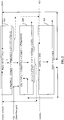
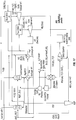
- FIG. 1 is a block diagram of a system for a Group 2 hydroxide-based process to sequester CO 2 as Group 2 carbonates according to the present invention.
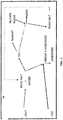
- FIG. 2 is a block diagram of a system in which Mg 2+ functions as a catalyst for the sequestration of CO 2 as calcium carbonate according to the present invention.
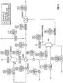
- FIG. 3 is a simplified process flow diagram according to some embodiments of the processes of the present invention.
- the term "road salt” in this figure refers to a Group II chloride, such as CaCl 2 and/or MgCl 2 , either or both of which are optionally hydrated.
- heat may be used to drive the reaction between road salt and water (including water of hydration) to form HCl and magnesium hydroxide, Mg(OH) 2 , and/or magnesium hydroxychloride, Mg(OH)Cl.
- heat may be used to drive the reaction between road salt and water to form calcium hydroxide and HCl.
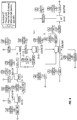
- FIG. 4 is a simplified process-flow diagram corresponding to some embodiments of the present invention.
- Silicate rocks are used in the present invention to sequester CO 2 as CaCO 3 .
- the term "road salt” in this figure refers to a Group II chloride, such as CaCl 2 and/or MgCl 2 , either or both of which are optionally hydrated.
- heat may be used to drive the reaction between road salt, e.g., MgCl 2 ⁇ 6H 2 O, and water (including water of hydration) to form HCl and Group II hydroxides, oxides, and/or mixed hydroxide-chlorides, including, for example, magnesium hydroxide, Mg(OH) 2 , and/or magnesium hydroxychloride, Mg(OH)Cl.
- road salt e.g., MgCl 2 ⁇ 6H 2 O
- water including water of hydration
- mixed hydroxide-chlorides including, for example, magnesium hydroxide, Mg(OH) 2 , and/or magnesium hydroxychloride, Mg(OH)Cl.
- CaCl 2 heat may be used to drive the reaction between road salt and water to form calcium hydroxide and HCl.
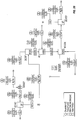
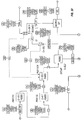
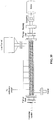
- FIG. 5 is a process flow diagram showing parameters and results from a process simulation using Aspen Plus process software.
- H 2 O-MgOH a 35% MgCl 2 , 65% H 2 O solution
- H 2 O-MgOH a solution of MgCl 2 and solid Mg(OH) 2
- Mg(OH)Cl dissolves in water it forms Mg(OH) 2 (solid) and MgCl 2 (dissolved).
- MgCl 2 is not used to absorb CO 2 directly, rather it is recycled.
- the net reaction is the capture of CO 2 from flue gas using inexpensive raw materials, CaCl 2 and water, to form CaCO 3 .
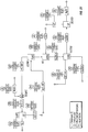
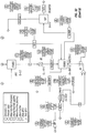
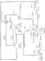
- FIG. 6 is a process flow diagram showing parameters and results from a process simulation using Aspen Plus process software. The net reaction is the capture of CO 2 from flue gas using inexpensive raw materials, CaCl 2 and water, to form CaCO 3 .
- the hexahydrate is dehydrated in three separate chambers and decomposed in the fourth chamber where the HCl that is formed from the decomposition is recirculated back to the third chamber to prevent any side reactions.
- Reactions occurring in these chambers include the following: 1 st Chamber: MgCl 2 ⁇ 6H 2 O ⁇ MgCl 2 ⁇ 4H 2 O + 2H 2 O 100 °C 2 nd Chamber: MgCl 2 ⁇ 4H 2 O ⁇ MgCl 2 ⁇ 2H 2 O + 2H 2 O 125 °C 3 rd Chamber: MgCl 2 ⁇ 2H 2 O ⁇ MgCl 2 ⁇ H 2 O + H 2 O 160 °C (HCl vapor present) 4 th Chamber: MgCl 2 ⁇ H 2 O ⁇ Mg(OH)Cl + HCl 130 °C HCl recirculates to the 3 rd chamber.
- the first three reactions above may be characterized as dehydrations, while the fourth may be characterized as a decomposition.
- Results from this simulation indicate that at lower temperatures (130-250 °C) the decomposition of MgCl 2 ⁇ 6H 2 O results in the formation of Mg(OH)Cl instead of MgO.
- the Mg(OH)Cl then reacts with H 2 O to form MgCl 2 and Mg(OH) 2 , which then reacts with a saturated CaCl 2 /H 2 O solution and CO 2 from the flue gas to form CaCO 3 , which is filtered out of the stream.
- the resulting MgCl 2 formed is recycled to the first reactor to begin the process again.
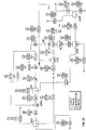
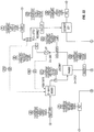
- FIG. 7 is a process flow diagram showing parameters and results from a process simulation using Aspen Plus process software.
- the net reaction is the capture of CO 2 from flue gas using inexpensive raw materials, CaCl 2 and water, to form CaCO 3 .
- the magnesium hexahydrate is dehydrated in two separate chambers and decomposed in a third chamber. Both dehydration and decomposition reactions occur in the third chamber. There is no recirculating HCl.
- Reactions occurring in these chambers include the following: 1 st Chamber: MgCl 2 ⁇ 6H 2 O ⁇ MgCl 2 ⁇ 4H 2 O + 2H 2 O 100 °C 2 nd Chamber: MgCl 2 ⁇ 4H 2 O ⁇ MgCl 2 ⁇ 2H 2 O + 2H 2 O 125 °C 3 rd Chamber: MgCl 2 ⁇ 2H 2 O ⁇ Mg(OH)Cl + HCl + H 2 O 130 °C 3 rd Chamber: MgCl 2 ⁇ 2H 2 O ⁇ MgCl 2 ⁇ H 2 O + H 2 O 130 °C Chamber Reaction Model Temp. Preferred Temp.
- the first, second and fourth reactions above may be characterized as dehydrations, while the third may be characterized as a decomposition.
- the temperatures used in this embodiment result in the formation of Mg(OH)Cl from the MgCl 2 ⁇ 6H 2 O rather than MgO.
- the Mg(OH)Cl then reacts with H 2 O to form MgCl 2 and Mg(OH) 2 , which reacts with a saturated CaCl 2 /H 2 O solution and CO 2 from the flue gas to form CaCO 3 , which is filtered out of the stream.
- the resulting MgCl 2 formed is recycled to the first reactor to begin the process again. Additional details regarding this simulation are provided in Example 3 below.
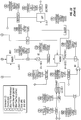
- FIG. 8 is a process flow diagram showing parameters and results from a process simulation using Aspen Plus process software.
- the net reaction is the capture of CO 2 from flue gas using inexpensive raw materials, CaCl 2 and water, to form CaCO 3 .
- Results from this simulation indicate that it is efficient to heat MgCl 2 ⁇ 6H 2 O to form MgO.
- the MgO then reacts with H 2 O to form Mg(OH) 2 , which then reacts with a saturated CaCl 2 /H 2 O solution and CO 2 from the flue gas to form CaCO 3 , which is filtered out of the stream.
- the resulting MgCl 2 formed is recycled to the first reactor to begin the process again.
- the magnesium hexahydrate is simultaneously dehydrated and decomposed in one chamber at 450 °C.
- This is the model termperature range.
- the preferred range in some emobodiments, is 450 °C - 500 °C.
- the main reaction occurring in this chamber can be represented as follows: MgCl 2 ⁇ 6H 2 O ⁇ MgO + 5H 2 O + 2HCl 450 °C
- FIG. 9 is a process flow diagram showing parameters and results from a process simulation using Aspen Plus process software similar to the embodiment of FIG. 8 except that the MgCl 2 ⁇ 6H 2 O is decomposed into an intermediate compound, Mg(OH)Cl at a lower temperature of 250 °C in one chamber.
- the Mg(OH)Cl is then dissolved in water to form MgCl 2 and Mg(OH) 2 , which follows through with the same reaction with CaCl 2 and CO 2 to form CaCO 3 and MgCl 2 .
- the main reaction occurring in this chamber can be represented as follows: MgCl 2 ⁇ 6H 2 O ⁇ Mg(OH)Cl + HCl + 5H 2 O 250 °C
- the reaction was modeled at 250 °C. In some embodiments, the preferred range is from 230 °C to 260 °C. Additional details regarding this simulation are provided in Example 5 below.
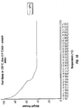
- FIG. 10 shows a graph of the mass percentage of a heated sample of MgCl 2 ⁇ 6H 2 O.
- the sample's initial mass was approximately 70 mg and set at 100%.
- the temperature was quickly ramped up to 150 °C, and then slowly increased by 0.5 °C per minute. At approximately 220 °C, the weight became constant, consistent with the formation of Mg(OH)Cl.
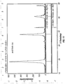
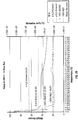
- FIG. 11 shows X-ray diffraction data corresponding to the product of Example 7.
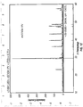
- FIG. 12 shows X-ray diffraction data corresponding to the product from the reaction using Mg(OH) 2 of Example 8.
- FIG. 13 shows X-ray diffraction data corresponding to the product from the reaction using Mg(OH)Cl of Example 8.
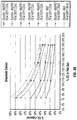
- FIG. 14 shows the effect of temperature and pressure on the decomposition of MgCl 2 ⁇ (H 2 O).
- FIG. 15 is a process flow diagram of an embodiment of the Ca/Mg process described herein.
- FIG. 16 is a process flow diagram of a variant of the process, whereby only magnesium compounds are used. In this embodiment the Ca 2+ - Mg 2+ switching reaction does not occur.
- FIG. 17 is a process flow diagram of a different variant of the process which is in between the previous two embodiments.
- Half of the Mg 2+ is replaced by Ca 2+ , thereby making the resulting mineralized carbonate MgCa(CO 3 ) 2 or dolomite.
- This figure shows a process flow diagram providing parameters and results from a process simulation using Aspen Plus process software.
- the net reaction is the capture of CO 2 from flue gas using inexpensive raw materials, CaSiO 3 , CO 2 and water, to form SiO 2 and CaCO 3 .
- Results from this simulation indicate that it is efficient to use heat from the HCl reacting with CaSiO 3 and heat from the flue gas emitted by a natural gas or coal fired power plant to carry out the decomposition of MgCl 2 ⁇ 6H 2 O to form Mg(OH)Cl.
- the Mg(OH)Cl then reacts with H 2 O to form MgCl 2 and Mg(OH) 2 , which then reacts with a saturated CaCl 2 /H 2 O solution and CO 2 from the flue gas to form CaCO 3 , which is filtered out of the stream.
- the resulting MgCl 2 formed is recycled to the first reactor to begin the process again.
- the magnesium chloride hexahydrate is dehydrated to magnesium chloride dihydrate MgCl 2 ⁇ 2H 2 O in the first chamber using heat from the HCl and CaSiO 3 reaction and decomposed in a second chamber at 250°C using heat from the flue gas.
- the decomposition goes partially to Mg(OH)Cl.
- the main reactions occurring in this chamber can be represented as follows: Reaction ⁇ H ** kJ/mole Reaction Temp. Range MgCl 2 ⁇ 6H 2 O ⁇ Mg(OH)Cl + 5H 2 O + HCl 433 230 °C - 260 °C 2HCl( g ) + CaSiO 3 ⁇ CaCl 2 ( aq ) + H 2 O + SiO 2 ⁇ -259 90 °C-150 °C 2Mg(OH)Cl + CO 2 + CaCl 2 ⁇ 2MgCl 2 + CaCO 3 ⁇ + H 2 O -266 25 °C - 95 °C ** Enthalpies are based on reaction temperatures, and temperatures of incoming reactant and outgoing product streams. Additional details regarding this simulation are provided in Examples 10 and 11 below.
- This figure shows a process flow diagram providing parameters and results from a process simulation using Aspen Plus process software.
- the net reaction is the capture of CO 2 from flue gas using inexpensive raw materials, CaSiO 3 , CO 2 and water, to form SiO 2 and CaCO 3 .
- Results from this simulation indicate that it is efficient to use heat from the HCl reacting with CaSiO 3 and heat from flue gas emitted by a natural gas or coal fired power plant to carry out the decomposition of MgCl 2 ⁇ 6H 2 O to form MgO.
- the MgO then reacts with H 2 O to form Mg(OH) 2 , which then reacts with a saturated CaCl 2 /H 2 O solution and CO 2 from the flue gas to form CaCO 3 , which is filtered out of the stream.
- the resulting MgCl 2 formed is recycled to the first reactor to begin the process again.
- the magnesium chloride hexahydrate is dehydrated to magnesium chloride dihydrate MgCl 2 ⁇ 2H 2 O in the first chamber using heat from the HCl and CaSiO 3 reaction and decomposed in a second chamber at 450°C using heat from the flue gas.
- the decomposition goes completely to MgO.
- the main reactions occurring in this chamber can be represented as follows: Reaction ⁇ H kJ/mole** Reaction Temp. Range MgCl 2 ⁇ 6H 2 O ⁇ MgO + 5H 2 O + 2HCl 560 450 °C - 500 °C 2HCl(g) + CaSiO 3 ⁇ CaCl 2 ( aq ) + H 2 O + SiO 2 ⁇ -264 90 °C - 150 °C MgO + CO 2 + CaCl 2 ( aq ) ⁇ MgCl 2 ( aq ) + CaCO 3 ⁇ -133 25 °C - 95 °C ** Enthalpies are based on reaction temperatures, and temperatures of incoming reactant and outgoing product streams. Additional details regarding this simulation are provided in Examples 12 and 13 below.
- This figure shows a process flow diagram providing parameters and results from a process simulation using Aspen Plus process software.
- the net reaction is the capture of CO 2 from flue gas using inexpensive raw materials, MgSiO 3 , CO 2 and water, to form SiO 2 and MgCO 3 .
- Results from this simulation indicate that it is efficient to use heat from the HCl reacting with MgSiO 3 and heat from the flue gas emitted by a natural gas or coal fired power plant to carry out the decomposition of MgCl 2 ⁇ 2H 2 O to form Mg(OH)Cl.
- the Mg(OH)Cl then reacts with H 2 O to form MgCl 2 and Mg(OH) 2 , which then reacts with CO 2 from the flue gas to form MgCO 3 , which is filtered out of the stream.
- the resulting MgCl 2 formed is recycled to the first reactor to begin the process again.
- the magnesium chloride remains in the dihydrate form MgCl 2 ⁇ 2H 2 O due to the heat from the HCl and MgSiO 3 prior to decomposition at 250°C using heat from the flue gas.
- the main reactions occurring in this chamber can be represented as follows: Reaction ⁇ H kJ/mole ** Reaction Temp.
- This figure shows a process flow diagram providing parameters and results from a process simulation using Aspen Plus process software.
- the net reaction is the capture of CO 2 from flue gas using inexpensive raw materials, MgSiO 3 , CO 2 and water, to form SiO 2 and MgCO 3 .
- Results from this simulation indicate that it is efficient to use heat from the HCl reacting with MgSiO 3 and heat from the flue gas emitted by a natural gas or coal fired power plant to carry out the decomposition of MgCl 2 ⁇ 2H 2 O to form MgO.
- the MgO then reacts with H 2 O to form Mg(OH) 2 , which then reacts with CO 2 from the flue gas to form MgCO 3 , which is filtered out of the stream.
- the magnesium chloride remains in the dihydrate form MgCl 2 ⁇ 2H 2 O due to the heat from the HCl and MgSiO 3 prior to decomposition at 450°C using heat from the flue gas.
- the main reactions occurring in this chamber can be represented as follows: Reaction ⁇ H kJ/mole ** Reaction Temp.
- FIG. 22 Diopside-Mg(OH)Cl Process, Cases 18 & 19.
- This figure shows a process flow diagram providing parameters and results from a process simulation using Aspen Plus process software.
- the net reaction is the capture of CO 2 from flue gas using inexpensive raw materials, diopside MgCa(SiO 3 ) 2 , CO 2 and water, to form SiO 2 and dolomite MgCa(CO 3 ) 2 .
- Results from this simulation indicate that it is efficient to use heat from the HCl reacting with MgCa(SiO 3 ) 2 and heat from the flue gas emitted by a natural gas or coal fired power plant to carry out the decomposition of MgCl 2 ⁇ 6H 2 O to form Mg(OH)Cl.
- the Mg(OH)Cl then reacts with H 2 O to form MgCl 2 and Mg(OH) 2 , which then reacts with a saturated CaCl 2 /H 2 O solution and CO 2 from the flue gas to form MgCa(CO 3 ) 2 which is filtered out of the stream.
- the resulting MgCl 2 formed is recycled to the first reactor to begin the process again.
- the magnesium chloride hexahydrate is dehydrated to magnesium chloride dihydrate MgCl 2 ⁇ 2H 2 O in the first chamber using heat from the HCl and CaSiO 3 reaction and decomposed to Mg(OH)Cl in a second chamber at 250°C using heat from the flue gas.
- FIG. 23 Diopside-MgO Process, Cases 20 & 21.
- This figure shows a process flow diagram providing parameters and results from a process simulation using Aspen Plus process software.
- the net reaction is the capture of CO 2 from flue gas using inexpensive raw materials, diopside MgCa(SiO 3 ) 2 , CO 2 and water, to form SiO 2 and dolomite MgCa(CO 3 ) 2 .
- Results from this simulation indicate that it is efficient to use heat from the HCl reacting with MgCa(SiO 3 ) 2 and heat from the flue gas emitted by a natural gas or coal fired power plant and/or other heat source to carry out the decomposition of MgCl 2 ⁇ 6H 2 O to form MgO.
- the MgO then reacts with H 2 O to form Mg(OH) 2 , which then reacts with a saturated CaCl 2 /H 2 O solution and CO 2 from the flue gas to form MgCa(CO 3 ) 2 which is filtered out of the stream.
- the resulting MgCl 2 formed is recycled to the first reactor to begin the process again.
- the magnesium chloride hexahydrate is dehydrated to magnesium chloride dihydrate MgCl 2 ⁇ 2H 2 O in the first chamber using heat from the HCl and CaSiO 3 reaction and decomposed to MgO in a second chamber at 450°C using heat from the flue gas.
- the main reactions occurring in this chamber can be represented as follows: Reaction ⁇ H kJ/mole** Reaction Temp. Range MgCl 2 ⁇ 6H 2 O ⁇ MgO + 5H 2 O + 2HCl 560 450 °C - 500°C 2HCl(g) + MgCa(SiO 3 ) 2 ⁇ CaCl 2 ( g ) + MgSiO 3 ⁇ + SiO 2 ⁇ + H 2 O -240 90 °C-150 °C 2HCl( aq ) + MgSiO 3 ⁇ MgCl 2 ( aq ) + SiO 2 ⁇ + H 2 O -288 90 °C - 150 °C 2MgO + 2CO 2 + CaCl 2 ( aq ) ⁇ MgCa(CO 3 ) 2 ⁇ + MgCl 2 ( aq ) -258 25 °C - 95 °C ** Enthalpies are based on reaction temperatures, and temperatures of
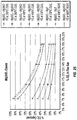
- FIG. 24 illustrates the percent CO 2 captured for varying CO 2 flue gas concentrations, varying temperatures, whether the flue gas was originated from coal or natural gas, and also whether the process relied on full or partial decomposition. See Examples 10 through 13 of the CaSiO 3 -Mg(OH)Cl and CaSiO 3 -MgO processes.
- FIG. 25 illustrates the percent CO 2 captured for varying CO 2 flue gas concentrations, varying temperatures, whether the flue gas was originated from coal or natural gas, and also whether the process relied on full or partial decomposition. See Examples 14 through 17 of the MgSiO 3 -Mg(OH)Cl and MgSiO 3 -MgO processes.
- FIG. 26 illustrates the percent CO 2 captured for varying CO 2 flue gas concentrations, varying temperatures, whether the flue gas was originated from coal or natural gas, and also whether the process relied on full or partial decomposition. See Examples 18 through 21 of the Diopside - Mg(OH)Cl and Diopside - MgO processes.
- FIGS. 28-29 show graphs of the mass percentages of heated samples of MgCl 2 ⁇ 6H 2 O.
- the initial masses of the samples were approximately 70 mg each and were each set at 100%.
- the temperature was ramped up to 200 °C then further increased over the course of a 12 hour run.
- the identities of the decomposed materials can be confirmed by comparing against the theoretical plateaus provided.
- FIG. 28 is a superposition of two plots, the first one being the solid line, which is a plot of time (minutes) versus temperature (°C).
- FIG. 29 is also a superposition of two plots, the first (the solid line) is a plot of weight% versus temperature (°C), illustrating the sample's weight decreasing as the temperature increases; the second plot (the dashed line) is a plot of the derivative of the weight% with respect to temperature (wt.%/°C) versus temperature °C. When this value is high it indicates a higher rate of weight loss for each change per degree. If this value is zero, the sample's weight remains the same although the temperature is increasing, indicating an absence of dehydration or decomposition. Note Figure 28 and 29 are of the same sample.
- FIG. 30 MgCl 2 ⁇ 6H 2 O Decomposition at 500°C after One Hour.
- This graph shows the normalized final and initial weights of four test runs of MgCl 2 ⁇ 6H 2 O after heating at 500 °C for one hour. The consistent final weight confirms that MgO is made by decomposition at this temperature.
- FIG. 31 Three-Chamber Decomposition.
- This figure shows a process flow diagram providing parameters and results from a process simulation using Aspen Plus process software.
- heat from cold flue gas (chamber 1)
- heat from mineral dissolution reactor (chamber 2)
- external natural gas (chamber 3) are used as heat sources.
- This process flow diagram illustrates a three chamber process for the decomposition to Mg(OH)Cl.
- the first chamber is heated by 200 °C flue gas to provide some initial heat about ⁇ 8.2% of the total required heat
- the second chamber which relies on heat recovered from the mineral dissolution reactor to provide 83% of the needed heat for the decomposition of which 28% is from the hydrochloric acid/mineral silicate reaction and 55% is from the condensation and formation of hydrochloric acid
- the third chamber which uses natural gas as an external source of the remaining heat which is 8.5% of the total heat.
- the CO 2 is from a combined cycle power natural gas plant, so very little heat is available from the power plant to power the decomposition reaction.
- FIG. 32 Four-Chamber Decomposition. This figure shows a process flow diagram providing parameters and results from a process simulation using Aspen Plus process software.
- heat from cold flue gas (chamber 1), heat from additional steam (chamber 2), heat from mineral dissolution reactor (chamber 3), and external natural gas (chamber 4) are used as heat sources.
- This process flow diagram illustrates a four chamber process for the decomposition to Mg(OH)Cl
- the first chamber provides 200 °C flue gas to provide some initial heat about ⁇ 8.2% of the total required heat
- the second chamber provides heat in the form of extra steam which is 0.8% of the total heat needed
- the third chamber which relies on heat recovered from the mineral dissolution reactor to provide 83% of the needed heat for the decomposition of which 28% is from the hydrochloric acid/mineral silicate reaction and 55% is from the condensation and formation of hydrochloric acid
- the fourth chamber which uses natural gas as an external source of the remaining heat which is 8.0% of the total heat.
- the CO 2 is from a combined cycle natural gas power plant, so very little heat is available from the power plant to power the decomposition reaction.
- FIG. 33 Two-Chamber Decomposition.
- This figure shows a process flow diagram providing parameters and results from a process simulation using Aspen Plus process software.
- heat from mineral dissolution reactor (chamber 1), and external natural gas (chamber 2) are used as heat sources.
- This process flow diagram illustrates a two chamber process for the decomposition to Mg(OH)Cl, the first chamber which relies on heat recovered from the mineral dissolution reactor to provide 87% of the needed heat for the decomposition of which 28% is from the hydrochloric acid/mineral silicate reaction and 59% is from the condensation and formation of hydrochloric acid, and the second chamber, which uses natural gas as an external source of the remaining heat which is 13% of the total heat.
- the CO 2 is from a combined cycle natural gas power plant, so very little heat is available from the power plant to power the decomposition reaction.
- FIG. 34 Two-Chamber Decomposition.
- This figure shows a process flow diagram providing parameters and results from a process simulation using Aspen Plus process software.
- heat from mineral dissolution reactor (chamber 1), and hot flue gas from open cycle natural gas plant (chamber 2) are used as heat sources.
- This process flow diagram illustrates a two chamber process for the decomposition to Mg(OH)Cl, the first chamber which relies on heat recovered from the mineral dissolution reactor to provide 87% of the needed heat for the decomposition of which 28% is from the hydrochloric acid/mineral silicate reaction and 59% is from the condensation and formation of hydrochloric acid, and the second chamber, which uses hot flue gas as an external source of the remaining heat which is 13% of the total heat.
- the CO 2 is from an open cycle natural gas power plant, therefore substantial heat is available from the power plant in the form of 600 °C flue gas to power the decomposition reaction.
- FIG. 35 shows a schematic diagram of a Auger reactor which may be used for the salt decomposition reaction, including the decomposition of MgCl 2 ⁇ 6H 2 O to M(OH)Cl or MgO.
- Such reactors may comprises internal heating for efficient heat utilization, external insulation for efficient heat utilization, a screw mechanism for adequate solid transport (when solid is present), adequate venting for HCl removal.
- Such a reactors has been used to prepare ⁇ 1.8kg of ⁇ 90% Mg(OH)Cl.
- FIG. 36 shows the optimization index for two separate runs of making Mg(OH)Cl using an Auger reactor.
- the optimization index % conversion ⁇ % efficiency.
- FIG. 37 shows a process flow diagram of an Aspen model that simulates an CaSiO 3 -Mg(OH)Cl Process.
- the present invention relates to carbon dioxide sequestration, including energy-efficient processes in which Group 2 chlorides are converted to Group 2 hydroxides and hydrogen chloride, which are then used to remove carbon dioxide from waste streams.
- the hydrogen chloride is further reacted with Group 2 silicates to produce additional Group 2 chloride starting materials and silica.
- the methods of the invention comprise one or more of the following general components: (1) the conversion of Group 2 silicate minerals with hydrogen chloride into Group 2 chlorides and silicon dioxide, (2) conversion of Group 2 chlorides into Group 2 hydroxides and hydrogen chloride, (3) an aqueous decarbonation whereby gaseous CO 2 is absorbed into an aqueous caustic mixture comprising Group 2 hydroxides to form Group 2 carbonate and/or bicarbonate products and water, (4) a separation process whereby the carbonate and/or bicarbonate products are separated from the liquid mixture, (5) the reuse or cycling of by-products, including energy, from one or more of the steps or process streams into another one or more steps or process streams.
- each of these general components is explained in further detail below.
- one advantage of certain embodiments of the present invention is that they provide ecological efficiencies that are superior to those of the prior art, while absorbing most or all of the emitted CO 2 from a given source, such as a power plant.
- carbonates or “carbonate products” are generally defined as mineral components containing the carbonate group, [CO 3 ] 2- . Thus, the terms encompass both carbonate/bicarbonate mixtures and species containing solely the carbonate ion.
- carbonates and “bicarbonate products” are generally defined as mineral components containing the bicarbonate group, [HCO 3 ] 1- . Thus, the terms encompass both carbonate/bicarbonate mixtures and species containing solely the bicarbonate ion.
- Ca/Mg signifies either Ca alone, Mg alone or a mixture of both Ca and Mg.
- the ratio of Ca to Mg may range from 0:100 to 100:0, including, e.g., 1:99, 5:95, 10:90, 20:80, 30:70, 40:60, 50:50, 60:40, 70:30, 80:20, 90:10, 95:5, and 99:1.
- the symbols "Ca/Mg”, “Mg x Ca (1-x) " and Ca x Mg (1-x )" are synonymous.
- “CaMg” or “MgCa” refers to a 1:1 ratio of these two ions.
- ecological efficiency is used synonymously with the term “thermodynamic efficiency” and is defined as the amount of CO 2 sequestered by certain embodiments of the present invention per energy consumed (represented by the equation " ⁇ CO 2 / ⁇ E"), appropriate units for this value are kWh/ton CO 2 .
- CO 2 sequestration is denominated in terms of percent of total plant CO 2 ; energy consumption is similarly denominated in terms of total plant power consumption.
- “Hexahydrate” refers to MgCl 2 ⁇ 6H 2 O.
- the term "ion ratio” refers to the ratio of cations in the product divided by the number of carbons present in that product.
- a product stream formed of calcium bicarbonate (Ca(HCO 3 ) 2 ) may be said to have an "ion ratio" of 0.5 (Ca/C)
- a product stream formed of pure calcium carbonate (CaCO 3 ) may be said to have an "ion ratio” of 1.0 (Ca/C).
- an infinite number of continuous mixtures of carbonate and bicarbonate of mono-, di- and trivalent cations may be said to have ion ratios varying between 0.5 and 3.0.
- MW either means molecular weight or megawatts.
- PFD process flow diagram
- Q heat (or heat duty), and heat is a type of energy. This does not include any other types of energy.
- the term "sequestration” is used to refer generally to techniques or practices whose partial or whole effect is to remove CO 2 from point emissions sources and to store that CO 2 in some form so as to prevent its return to the atmosphere. Use of this term does not exclude any form of the described embodiments from being considered “sequestration” techniques.
- W refers to H 2 O.
- the pyroxenes are a group of silicate minerals found in many igneous and metamorphic rocks. They share a common structure consisting of single chains of silica tetrahedra and they crystallize in the monoclinic and orthorhombic systems. Pyroxenes have the general formula XY(Si,Al) 2 O 6 , where X represents calcium, sodium, iron (II) and magnesium and more rarely zinc, manganese and lithium and Y represents ions of smaller size, such as chromium, aluminium, iron(III), magnesium, manganese, scandium, titanium, vanadium and even iron (II).
- atoms making up the compounds of the present invention are intended to include all isotopic forms of such atoms.
- Isotopes include those atoms having the same atomic number but different mass numbers.
- isotopes of hydrogen include tritium and deuterium
- isotopes of carbon include 13 C and 14 C.
- FIG. 1 depicts a simplified process-flow diagram illustrating general, exemplary embodiments of the apparatuses and methods of the present disclosure. This diagram is offered for illustrative purposes only, and depicts specific embodiments of the present invention.
- reactor 10 uses power, such as external power and/or recaptured power (e.g., heat from hot flue gas or an external source of heat such as solar concentration or combustion), to drive a reaction represented by equation 1.
- external power and/or recaptured power e.g., heat from hot flue gas or an external source of heat such as solar concentration or combustion
- the water used in this reaction may be in the form of liquid, steam, a crystalline hydrate, e.g ., MgCl 2 ⁇ 6H 2 O, CaCl 2 ⁇ 2H 2 O, or it may be supercritical.
- the reaction uses MgCl 2 to form Mg(OH) 2 and/or Mg(OH)Cl (see, e.g., FIG. 2 ). In some embodiments, the reaction uses CaCl 2 to form Ca(OH) 2 .
- Some or all of the Group 2 hydroxide or hydroxychloride (not shown) from equation 1 are delivered to reactor 20. In some embodiments, some or all of the Group 2 hydroxide and/or Group 2 hydroxychloride is delivered to reactor 20 as an aqueous solution. In some embodiments, some or all of the Group 2 hydroxide is delivered to reactor 20 in an aqueous suspension. In some embodiments, some or all of the Group 2 hydroxide is delivered to reactor 20 as a solid.
- Some or all of the hydrogen chloride (e.g., in the form of vapor or in the form of hydrochloric acid) is delivered to reactor 30 (e.g., a rock melter).
- reactor 30 e.g., a rock melter
- the resulting Group 2 hydroxides are further heated to remove water and form corresponding Group 2 oxides.
- some or all of these Group 2 oxides may then be delivered to reactor 20.
- Carbon dioxide from a source enters the process at reactor 20 (e.g., a fluidized bed reactor, a spray-tower decarbonator or a decarbonation bubbler), potentially after initially exchanging waste-heat with a waste-heat/DC generation system.
- reactor 20 e.g., a fluidized bed reactor, a spray-tower decarbonator or a decarbonation bubbler
- the temperature of the flue gas is at least 125 °C.
- the Group 2 hydroxide, some or all of which may be obtained from reactor 10 reacts with carbon dioxide in reactor 20 according to the reaction represented by equation 2. (Ca/Mg)(OH) 2 + CO 2 ⁇ (Ca/Mg)CO 3 + H 2 O (2)
- the water produced from this reaction may be delivered back to reactor 10.
- the Group 2 carbonate is typically separated from the reaction mixture.
- Group 2 carbonates have a very low K sp (solubility product constant). So they be separated as solids from other, more soluble compounds that can be kept in solution.
- the reaction proceeds through Group 2 bicarbonate salts.
- Group 2 bicarbonate salts are generated and optionally then separated from the reaction mixture.
- Group 2 oxides, optionally together with or separately from the Group 2 hydroxides, are reacted with carbon dioxide to also form Group 2 carbonate salts.
- the flue gas, from which CO 2 and/or other pollutants have been removed, is released to the air.
- Group 2 silicates enter the process at reactor 30 (e.g., a rock melter or a mineral dissociation reactor).
- reactor 30 e.g., a rock melter or a mineral dissociation reactor.
- these Group 2 silicates are ground in a prior step.
- the Group 2 silicates are inosilicates.
- These minerals may be reacted with hydrochloric acid, either as a gas or in the form of hydrochloric acid, some or all of which may be obtained from reactor 10, to form the corresponding Group 2 metal chlorides (CaCl 2 and/or MgCl 2 ), water and sand (SiO 2 ).
- the reaction can be represented by equation 3. 2 HCl + (Ca/Mg)SiO 3 ⁇ (Ca/Mg)Cl 2 + H 2 O + SiO 2 (3) Some or all of the water produced from this reaction may be delivered to reactor 10. Some or all of the Group 2 chlorides from equation 3 may be delivered to reactor 20. In some embodiments, some or all of the Group 2 chloride is delivered to reactor 20 as an aqueous solution. In some embodiments, some or all of the Group 2 chloride is delivered to reactor 20 in an aqueous suspension. In some embodiments, some or all of the Group 2 chloride is delivered to reactor 20 as a solid.
- Equation 4 CO 2 + (Ca/Mg)SiO 3 ⁇ (Ca/Mg)CO 3 + SiO 2 (4)
- the resulting Mg x Ca (1-x )CO 3 sequestrant is reacted with HCl in a manner to regenerate and concentrate the CO 2 .
- the Ca/MgCl 2 thus formed is returned to the decomposition reactor to produce CO 2 absorbing hydroxides or hydroxyhalides.
- Group 2 carbonates are generated as end-sequestrant material from the captured CO 2 .
- Some or all of the water, hydrogen chloride and/or reaction energy may be cycled. In some embodiments, only some or none of these are cycled. In some embodiments, the water, hydrogen chloride and reaction energy made be used for other purposes.
- the methods disclosed herein may be used to capture 33-66% of the plant's CO 2 using heat-only as the driver (no electrical penalty).
- the efficiencies of the methods disclosed herein improve with lower CO 2 -concentrations, and increase with higher (unscrubbed) flue-gas temperatures. For example, at 320 °C and 7% CO 2 concentration, 33% of flue-gas CO 2 can be mineralized from waste-heat alone. In other embodiments, e.g ., at the exit temperatures of natural gas turbines approximately 100% mineralization can be achieved.
- FIG. 2 depicts a simplified process-flow diagram illustrating general, exemplary embodiments of the apparatuses and methods of the present disclosure. This diagram is offered for illustrative purposes only, and depicts specific embodiments of the present invention.
- reactor 100 uses power, such as external power and/or recaptured power (e.g ., heat from hot flue gas), to drive a decomposition -type reaction represented by equation 5.
- power such as external power and/or recaptured power (e.g ., heat from hot flue gas)
- a decomposition -type reaction represented by equation 5.
- the water used in this reaction may be in the form of a hydrate of magnesium chloride, liquid, steam and/or it may be supercritical. In some embodiments, the reaction may occur in one, two, three or more reactors.
- the reaction may occur as a batch, semi-batch of continuous process.
- Some or all of the magnesium salt product are delivered to reactor 200.
- some or all of the magnesium salt product is delivered to reactor 200 as an aqueous solution.
- some or all of the magnesium salt product is delivered to reactor 200 in an aqueous suspension.
- some or all of the magnesium salt product is delivered to reactor 200 as a solid.
- some or all of the hydrogen chloride e.g ., in the form of vapor or in the form of hydrochloric acid
- reactor 300 e.g., a rock melter
- the Mg(OH) 2 is further heated to remove water and form MgO.
- the MgCl(OH) is further heated to remove HCl and form MgO.
- one or more of Mg(OH) 2 , MgCl(OH) and MgO may then be delivered to reactor 200.
- Carbon dioxide from a source enters the process at reactor 200 (e.g., a fluidized bed reactor, a spray-tower decarbonator or a decarbonation bubbler), potentially after initially exchanging waste-heat with a waste-heat/DC generation system.
- reactor 200 e.g., a fluidized bed reactor, a spray-tower decarbonator or a decarbonation bubbler
- the temperature of the flue gas is at least 125 °C.
- Admixed with the carbon dioxide is the magnesium salt product from reactor 100 and CaCl 2 ( e.g., rock salt). The carbon dioxide reacts with the magnesium salt product and CaCl 2 in reactor 200 according to the reaction represented by equation 6.
- the water produced from this reaction may be delivered back to reactor 100.
- the calcium carbonate product e.g., limestone, calcite
- the reaction proceeds through magnesium carbonate and bicarbonate salts.
- the reaction proceeds through calcium bicarbonate salts.
- various Group 2 bicarbonate salts are generated and optionally then separated from the reaction mixture.
- the flue gas, from which CO 2 and/or other pollutants have been removed is released to the air, optionally after one or more further purification and/or treatment steps.
- the MgCl 2 product, optionally hydrated is returned to reactor 100.
- the MgCl 2 product is subjected to one or more isolation, purification and/or hydration steps before being returned to reactor 100.
- Calcium silicate e.g ., 3CaO ⁇ SiO 2 , Ca 3 SiO 5 ; 2CaO ⁇ SiO 2 , Ca 2 SiO 4 ; 3CaO ⁇ 2SiO 2 , Ca 3 Si 2 O 7 and CaO ⁇ SiO 2 , CaSiO 3 enters the process at reactor 300 ( e.g., a rock melter).
- reactor 300 e.g., a rock melter
- these Group 2 silicates are ground in a prior step.
- the Group 2 silicates are inosilicates. In the embodiment of FIG.
- the inosilicate is CaSiO 3 (e.g., wollastonite, which may itself, in some embodiments, contain small amounts of iron, magnesium and/or manganese substituting for iron).
- the CaSiO 3 is reacted with hydrogen chloride, either gas or in the form of hydrochloric acid, some or all of which may be obtained from reactor 100, to form CaCl 2 , water and sand (SiO 2 ).
- the reaction can be represented by equation 7. 2 HCl + (Ca/Mg)SiO 3 ⁇ (Ca/Mg)Cl 2 + H 2 O + SiO 2 (7) Reaction ⁇ H kJ/mole** Reaction Temp.
- Equation 8 The net reaction capturing the summation of equations 5-7 is shown here as equation 8: CO 2 + CaSiO 3 ⁇ CaCO 3 + SiO 2 (8) Reaction ⁇ H kJ/mole** ⁇ G kJ/mole** CO 2 + CaSiO 3 ⁇ CaCO 3 + SiO 2 -89 -39 ** Measured at standard temperature and pressure (STP).
- STP standard temperature and pressure
- a Group 2 chloride e.g., CaCl 2 or MgCl 2
- water may be in the form of liquid, steam, from a hydrate of the Group 2 chloride, and/or it may be supercritical.
- the steam may come from a heat exchanger whereby heat from an enormous combustible reaction, i.e. natural gas and oxygen or hydrogen and chlorine heats a stream of water.
- steam may also be generated through the use of plant or factory waste heat.
- the chloride salt, anhydrous or hydrated is also heated.
- the reactions are endothermic meaning energy, e.g ., heat has to be applied to make these reactions occur. Such energy may be obtained from the waste-heat generated from one or more of the exothermic process steps disclosed herein.
- the salt MgCl 2 ⁇ 6H 2 O, magnesium hexahydrate is used. Since water is incorporated into the molecular structure of the salt, direct heating without any additional steam or water may be used to initiate the decomposition. Typical reactions temperatures for the following reactions are shown here: From 95-110 °C: MgCl 2 ⁇ 6H 2 O ⁇ MgCl 2 ⁇ 4H 2 O + 2 H 2 O (16) MgCl 2 ⁇ 4H 2 O ⁇ MgCl 2 ⁇ 2H 2 O + 2 H 2 O (17) From 135-180 °C: MgCl 2 ⁇ 4H 2 O ⁇ Mg(OH)Cl + HCl + 3 H 2 O (18) MgCl 2 ⁇ 2H 2 O ⁇ MgCl 2 ⁇ H 2 O + H 2 O (19) From 185-230 °C: MgCl 2 ⁇ 2H 2 O ⁇ Mg(OH)Cl + HCl +H 2 O (20) From >230 °C: Mg
- apparatuses and methods for the decarbonation of carbon dioxide sources using Group 2 hydroxides, Group 2 oxides, and/or Group 2 hydroxide chlorides as CO 2 adsorbents are provided.
- CO 2 is absorbed into an aqueous caustic mixture and/or solution where it reacts with the hydroxide and/or oxide salts to form carbonate and bicarbonate products.
- Sodium hydroxide, calcium hydroxide and magnesium hydroxide, in various concentrations, are known to readily absorb CO 2 .
- Group 2 hydroxides, Group 2 oxides (such as CaO and/or MgO) and/or other hydroxides and oxides, e.g ., sodium hydroxide may be used as the absorbing reagent.
- a Group 2 hydroxide e.g ., obtained from a Group 2 chloride
- a Group 2 hydroxide may be used in an adsorption tower to react with and thereby capture CO 2 based on one or both of the following reactions: Ca(OH) 2 + CO 2 ⁇ CaCO 3 + H 2 O (24)
- the reaction may be driven to completion, for example, through the removal of water, whether through continuous or discontinous processes, and/or by means of the precipitation of bicarbonate, carbonate, or a mixture of both types of salts. See example 1, below, providing a simulation demonstrating the ability to capture CO 2 from flue gas using an inexpensive raw material, Ca(CO) 2 derived from CaCl 2 , to form CaCO 3 .
- an initially formed Group 2 may undergo an salt exchange reaction with a second Group 2 hydroxide to transfer the carbonate anion.
- a second Group 2 hydroxide For example: CaCl 2 + MgCO 3 + ⁇ MgCl 2 + CaCO 3 (25a)
- the present invention provided methods of sequestering carbon dioxide using silicate minerals.
- the silicate minerals make up one of the largest and most important classes of rock-forming minerals, constituting approximately 90 percent of the crust of the Earth. They are classified based on the structure of their silicate group. Silicate minerals all contain silicon and oxygen. In the present invention, Group 2 silicates are used to accomplish the energy efficient sequestration of carbon dioxide.
- compositions comprising Group 2 inosilicates may be used.
- Inosilicates, or chain silicates have interlocking chains of silicate tetrahedra with either SiO 3 , 1:3 ratio, for single chains or Si 4 O 11 , 4:11 ratio, for double chains.
- compositions comprising Group 2 inosilicates from the pyroxene group.
- enstatite MgSiO 3
- MgSiO 3 enstatite
- compositions comprising Group 2 inosilicates from the pyroxenoid group are used.
- wollastonite CaSiO 3
- compositions comprising mixtures of Group 2 inosilicates may be employed, for example, mixtures of enstatite and wollastonite.
- compositions comprising mixed-metal Group 2 inosilicates may be used, for example, diopside (CaMgSi 2 O 6 ).
- Wollastonite usually occurs as a common constituent of a thermally metamorphosed impure limestone. Typically wollastonite results from the following reaction (equation 26) between calcite and silica with the loss of carbon dioxide: CaCO 3 + SiO 2 ⁇ CaSiO 3 + CO 2 (26)
- the present invention has the result of effectively reversing this natural process.
- Wollastonite may also be produced in a diffusion reaction in skarn. It develops when limestone within a sandstone is metamorphosed by a dyke, which results in the formation of wollastonite in the sandstone as a result of outward migration of calcium ions.
- the purity of the Group 2 inosilicate compositions may vary.
- the Group 2 inosilicate compositions used in the disclosed processes may contain varying amounts of other compounds or minerals, including non-Group 2 metal ions.
- wollastonite may itself contain small amounts of iron, magnesium, and manganese substituting for calcium.
- compositions comprising olivine and/or serpentine may be used.
- CO 2 mineral sequestration processes utilizing these minerals have been attempted.
- the techniques of Goldberg et al. (2001 ) are specifically referred to.
- the mineral olivine is a magnesium iron silicate with the formula (Mg,Fe) 2 SiO 4 . When in gem-quality, it is called peridot. Olivine occurs in both mafic and ultramafic igneous rocks and as a primary mineral in certain metamorphic rocks. Mg-rich olivine is known to crystallize from magma that is rich in magnesium and low in silica. Upon crystallization, the magna forms mafic rocks such as gabbro and basalt. Ultramafic rocks, such as peridotite and dunite, can be residues left after extraction of magmas and typically are more enriched in olivine after extraction of partial melts.
- Olivine and high pressure structural variants constitute over 50% of the Earth's upper mantle, and olivine is one of the Earth's most common minerals by volume.
- the metamorphism of impure dolomite or other sedimentary rocks with high magnesium and low silica content also produces Mg-rich olivine, or forsterite.
- Group 2 silicates e.g., CaSiO 3 , MgSiO 3 , and/or other silicates disclosed herein, are reacted with hydrochloric acid, either as a gas or in the form of aqueous hydrochloric acid, to form the corresponding Group 2 metal chlorides (CaCl 2 and/or MgCl 2 ), water and sand.
- the HCl produced in equation 1 is used to regenerate the MgCl 2 and/or CaCl 2 in equation 3.
- Table 1 below depicts some of the common calcium/magnesium containing silicate minerals that may be used, either alone or in combination. Initial tests by reacting olivine and serpentine with HCl have been successful.
- the conversion of carbon dioxide to mineral carbonates may be defined by two salts.
- the first salt is one that may be heated to decomposition until it becomes converted to a base (hydroxide and/or oxide) and emits an acid, for example, as a gas. This same base reacts with carbon dioxide to form a carbonate, bicarbonate or basic carbonate salt.
- the present disclosure provides processes that react one or more salts from Tables A-C below with water to form a hydroxides, oxides, and/or a mixed hydroxide halides. Such reactions are typically referred to as decompositions.
- the water may be in the form of liquid, steam, and/or from a hydrate of the selected salt.
- the steam may come from a heat exchanger whereby heat from an enormous combustible reaction, i.e. natural gas and oxygen or hydrogen and chlorine heats a stream of water.
- steam may also be generated through the use of plant or factory waste heat.
- the halide salt, anhydrous or hydrated is also heated. Table A.
- This same carbonate, bicarbonate or basic carbonate of the first salt reacts with a second salt to do a carbonate/bicarbonate exchange, such that the anion of second salt combines with the cation of the first salt and the cation of the second salt combines with the carbonate/bicarbonate ion of the first salt, which forms the final carbonate/bicarbonate.
- the hydroxide derived from the first salt is reacted with carbon dioxide and the second salt directly to form a carbonate/bicarbonate derived from (combined with the cation of) the second salt.
- the carbonate/bicarbonate/basic carbonate derived from (combined with the cation of) the first salt is removed from the reactor chamber and placed in a second chamber to react with the second salt.
- This reaction may be beneficial when making a carbonate/bicarbonate when a salt of the second metal is desired, and this second metal is not as capable of decomposing to form a CO 2 absorbing hydroxide, and if the carbonate/bicarbonate compound of the second salt is insoluble, i.e. it precipitates from solution.
- this reaction may be beneficial when making a carbonate/bicarbonate when a salt of the second metal is desired, and this second metal is not as capable of decomposing to form a CO 2 absorbing hydroxide, and if the carbonate/bicarbonate compound of the second salt is insoluble, i.e. it precipitates from solution.
- Known carbonate compounds include H 2 CO 3 , Li 2 CO 3 , Na 2 CO 3 , K 2 CO 3 , Rb 2 CO 3 , Cs 2 CO 3 , BeCO 3 , MgCO 3 , CaCO 3 , MgCO 3 , SrCO 3 , BaCO 3 , MnCO 3 , FeCO 3 , CoCO 3 , CuCO 3 , ZnCO 3 , Ag 2 CO 3 , CdCO 3 , Al 2 (CO 3 ) 3 , Tl 2 CO 3 , PbCO 3 , and La 2 (CO 3 ) 3 .
- Group IA elements are known to be stable bicarbonates, e.g ., LiHCO 3 , NaHCO 3 , RbHCO 3 , and CsHCO 3 .
- Group IIA and some other elements can also form bicarbonates, but in some cases, they may only be stable in solution.
- rock-forming elements are H, C, O, F, Na, Mg, Al, Si, P, S, Cl, K, Ca, Ti, Mg and Fe. Salts of these that can be thermally decomposed into corresponding hydroxides by the least amount of energy per mole of CO 2 absorbing hydroxide may therefore be considered potential Salt-1 candidates.
- Limestone is a sedimentary rock composed largely of the mineral calcite (calcium carbonate: CaCO 3 ). This mineral has many uses, some of which are identified below.
- Limestone in powder or pulverized form may be used as a soil conditioner (agricultural lime) to neutralize acidic soil conditions, thereby, for example, neutralizing the effects of acid rain in ecosystems.
- soil conditioner agricultural lime
- Upstream applications include using limestone as a reagent in desulfurizations.
- Limestone is an important stone for masonry and architecture. One of its advantages is that it is relatively easy to cut into blocks or more elaborate carving. It is also long-lasting and stands up well to exposure. Limestone is a key ingredient of quicklime, mortar, cement, and concrete.
- Calcium carbonate is also used as an additive for paper, plastics, paint, tiles, and other materials as both white pigment and an inexpensive filler. Purified forms of calcium carbonate may be used in toothpaste and added to bread and cereals as a source of calcium. CaCO 3 is also commonly used medicinally as an antacid.
- this invention provides a non-extractive source of this important product.
- MgCO 3 Magnesium carbonate, MgCO 3 , is a white solid that occurs in nature as a mineral.
- the most common magnesium carbonate forms are the anhydrous salt called magnesite (MgCO 3 ) and the di, tri, and pentahydrates known as barringtonite (MgCO 3 ⁇ 2H 2 O), nesquehonite (MgCO 3 ⁇ 3H 2 O), and lansfordite (MgCO 3 ⁇ 5H 2 O), respectively.
- MgCO 3 anhydrous salt
- Barringtonite MgCO 3 ⁇ 2H 2 O
- MgCO 3 ⁇ 3H 2 O nesquehonite
- MgCO 3 ⁇ 5H 2 O lansfordite
- Magnesium carbonate may be used to produce magnesium metal and basic refractory bricks. MgCO 3 is also used in flooring, fireproofing, fire extinguishing compositions, cosmetics, dusting powder, and toothpaste. Other applications are as filler material, smoke suppressant in plastics, a reinforcing agent in neoprene rubber, a drying agent, a laxative, and for color retention in foods. In addition, high purity magnesium carbonate is used as antacid and as an additive in table salt to keep it free flowing.
- magnesium carbonate is typically obtained by mining the mineral magnesite. By co-generating this mineral as part of carbon dioxide sequestration in some embodiments, this invention provides a non-extractive source of this important product.
- the present invention provided methods of sequestering carbon dioxide that produce silicon dioxide as a byproduct.
- Silicon dioxide also known as silica
- silica is an oxide of silicon with a chemical formula of SiO 2 and is known for its hardness.
- Silica is most commonly found in nature as sand or quartz, as well as in the cell walls of diatoms. Silica is the most abundant mineral in the Earth's crust. This compound has many uses; some of these are briefly discussed below.
- Silica is used primarily in the production of window glass, drinking glasses and bottled beverages.
- the majority of optical fibers for telecommunications are also made from silica. It is a primary raw material for many whiteware ceramics such as earthenware, stoneware and porcelain, as well as industrial Portland cement.
- Silica is a common additive in the production of foods, where it is used primarily as a flow agent in powdered foods, or to absorb water in hygroscopic applications. In hydrated form, silica is used in toothpaste as a hard abrasive to remove tooth plaque. Silica is the primary component of diatomaceous earth which has many uses ranging from filtration to insect control. It is also the primary component of rice husk ash which is used, for example, in filtration and cement manufacturing.
- Thin films of silica grown on silicon wafers via thermal oxidation methods can be quite beneficial in microelectronics, where they act as electric insulators with high chemical stability. In electrical applications, it can protect the silicon, store charge, block current, and even act as a controlled pathway to limit current flow.
- Silica is typically manufactured in several forms including glass, crystal, gel, aerogel, fumed silica, and colloidal silica. By co-generating this mineral as part of carbon dioxide sequestration in some embodiments, this invention provides another source of this important product.
- Separation processes may be employed to separate carbonate and bicarbonate products from the liquid solution and/or reaction mixture. By manipulating the basic concentration, temperature, pressure, reactor size, fluid depth, and degree of carbonation, precipitates of one or more carbonate and/or bicarbonate salts may be caused to occur. Alternatively, carbonate/bicarbonate products may be separated from solution by the exchange of heat energy with incoming flue-gases.
- the exit liquid streams may include water, CaCO 3 , MgCO 3 , Ca(HCO 3 ) 2 , Mg(HCO 3 ) 2 , Ca(OH) 2 , Ca(OH) 2 , NaOH, NaHCO 3 , Na 2 CO 3 , and other dissolved gases in various equilibria. Dissolved trace emission components such as H 2 SO 4 , HNO 3 , and Hg may also be found.
- removing/separating the water from the carbonate product involves adding heat energy to evaporate water from the mixture, for example, using a reboiler.
- retaining a partial basic solution and subsequently heating the solution in a separating chamber may be used to cause relatively pure carbonate salts to precipitate into a holding tank and the remaining hydroxide salts to recirculate back to the reactor.
- pure carbonate, pure bicarbonate, and mixtures of the two in equilibrium concentrations and/or in a slurry or concentrated form may then be periodically transported to a truck/tank-car.
- the liquid streams may be displaced to evaporation tanks/fields where the liquid, such as water, may be carried off by evaporation.
- the release of gaseous products includes a concern whether hydroxide or oxide salts will be released safely, i.e., emitting "basic rain.” Emission of such aerosolized caustic salts may be prevented in some embodiments by using a simple and inexpensive condenser/reflux unit.
- the carbonate salt may be precipitated using methods that are used separately or together with a water removal process.
- Various carbonate salt equilibria have characteristic ranges where, when the temperature is raised, a given carbonate salt, e.g., CaCO 3 will naturally precipitate and collect, which makes it amenable to be withdrawn as a slurry, with some fractional NaOH drawn off in the slurry.
- waste-heat recovery energy quantities may be found to entirely power embodiments of the present invention.
- some embodiments of the apparatuses and methods of the present disclosure produce a number of useful intermediates, by-products, and final products from the various reaction steps, including hydrogen chloride, Group 2 carbonate salts, Group 2 hydroxide salts, etc. In some embodiments, some or all of these may be used in one or more of the methods described below. In some embodiments, some or all of one of the starting materials or intermediates employed in one or more of the steps described above are obtained using one or more of the methods outlined below.
- the chlorine gas may be liquefied to hydrochloric acid that is then used to chlorinate Group 2 silicate minerals.
- Liquefaction of chlorine and subsequent use of the hydrochloric acid is particularly attractive especially in situations where the chlorine market is saturated. Liquefaction of chlorine may be accomplished according to equation 27: Cl 2 ( g ) + 2 H 2 O ( l ) + hv (363 nm) ⁇ 2 HCl ( l ) + 1 ⁇ 2 O 2 ( g ) (27)
- the oxygen so produced may be returned to the air-inlet of the power plant itself, where it has been demonstrated throughout the course of power-industry investigations that enriched oxygen-inlet plants have (a) higher Carnot-efficiencies, (b) more concentrated CO 2 exit streams, (c) lower heat-exchange to warm inlet air, and (d) other advantages over non-oxygen-enhanced plants.
- the oxygen may be utilized in a hydrogen/oxygen fuel cell.
- the oxygen may serve as part of the oxidant in a turbine designed for natural gas power generation, for example, using a mixture of hydrogen and natural gas.
- the chlorine gas may be reacted with a Group 2 hydroxide salts to yield a mixture of a chloride and a hypochlorite salts (equation 28).
- HCl may be sold as a product and the Group 2 hydroxide salt may be used to remove excess chlorine.
- the Group 2 hypochlorites may then be decomposed using a cobalt or nickel catalyst to form oxygen and the corresponding chloride (equation 29).
- Ca/Mg(OCl) 2 ⁇ Ca/MgCl 2 + O 2 The calcium chloride and/or the magnesium chloride may then be recovered.
- the decarbonation conditions will also remove SOx and NOx and, to a lesser extent, mercury.
- the incidental scrubbing of NOx, SOx, and mercury compounds can assume greater economic importance; i.e ., by employing embodiments of the present invention, coals that contain large amounts of these compounds can be combusted in the power plant with, in some embodiments, less resulting pollution than with higher-grade coals processed without the benefit of the CO 2 absorption process.
- Such principles and techniques are taught, for example, in U.S. Patent 7,727,374 , U.S. Patent Application No. 11/233,509, filed September 22, 2005 , U.S.
- Example 1 Process Simulation of Capture CO 2 from Flue Gas Using CaCl 2 to form CaCO 3 .
- reaction free energies and defined parameters to determine mass and energy balances and suitable conditions for capturing CO 2 from a flue gas stream utilizing CaCl 2 and heat to form CaCO 3 product were simulated. These results show that it is possible to capture CO 2 from flue gas using inexpensive raw materials, CaCl 2 and water, to form CaCO 3 .
- Part of the defined parameters includes the process flow diagram shown in FIG. 5 .
- Results from the simulation suggest that it is efficient to recirculate an MgCl 2 stream to react with H 2 O and heat to form Mg(OH) 2 .
- This Mg(OH) 2 then reacts with a saturated CaCl 2 /H 2 O solution and CO 2 from the flue gas to form CaCO 3 , which is filtered out of the stream.
- the resulting MgCl 2 formed is recycled to the first reactor to begin the process again.
- This process is not limited to any particular source for CaCl 2 . For example, it may be obtained from reacting calcium silicate with HCl to yield CaCl 2 .
- Constraints and parameters specified for this simulation include:
- Tables 2a and 2b provide mass and energy accounting for the various streams (the columns in the table) of the simulated process. Each stream corresponds to the stream of FIG. 5 .
- the process consists of two primary reaction sections and one solids filtration section.
- the first reactor heats MgCl 2 /water solution causing it to break down into a HCl/H 2 O vapor stream and a liquid stream of Mg(OH) 2 .
- the HCl/H 2 O vapor stream is sent to the HCl absorber column.
- the Mg(OH) 2 solution is sent to reactor 2 for further processing.
- the chemical reaction for this reactor can be represented by the following equation: MgCl 2 + 2 H 2 O ⁇ Mg(OH) 2 + 2HCl (30)
- a CaCl 2 solution and a flue gas stream are added to the MgCl 2 in reactor 2.
- This reaction forms CaCO 3 , MgCl 2 and water.
- the CaCO 3 precipitates and is removed in a filter or decanter.
- the remaining MgCl 2 and water are recycled to the first reactor. Additional water is added to complete the water balance required by the first reactor.
- the chemical reaction for this reactor can be represented by the following equation: Mg(OH) 2 + CaCl 2 + CO 2 ⁇ CaCO 3 ( s ) + MgCl 2 + H 2 O (31)
- the primary feeds to this process are CaCl 2 , flue gas (CO 2 ) and water.
- MgCl 2 in the system is used, reformed and recycled.
- the only MgCl 2 make-up required is to replace small amounts that leave the system with the CaCO 3 product, and small amounts that leave with the HCl/water product.
- This process is a net energy user. There is cross heat exchange to recover the heat in high temperature streams to preheat the feed streams. Significant heat recovery may be obtained by reacting the concentrated HCl thus formed with silicate minerals. Table 2a. Mass and Energy Accounting for Simulation of Capture CO 2 from Flue Gas Using CaCl 2 to form CaCO 3 .
- Example 2 (Case 1)- Process Simulation of Magnesium Ion Catalyzed Capture CO 2 from Flue Gas Using CaCl 2 to form CaCO 3 .
- results from the simulation suggest that it is efficient to heat a MgCl 2 ⁇ 6H 2 O stream in three separate dehydration reactions, each in its own chamber, followed by a decomposition reaction, also in its own chamber, to form Mg(OH)Cl and HCl, i.e. total of four chambers.
- the Mg(OH)Cl is reacted with H 2 O to form MgCl 2 and Mg(OH) 2 , which then reacts with a saturated CaCl 2 /H 2 O solution and CO 2 from the flue gas to form CaCO 3 , which is filtered out of the stream.
- the resulting MgCl 2 ⁇ 6H 2 O formed is recycled along with the earlier product to the first reactor to begin the process again.
- This process is not limited to any particular source for CaCl 2 .
- it may be obtained from reacting calcium silicate with HCl to yield CaCl 2 .
- Constraints and parameters specified for this simulation include:
- Table 3 provides mass and energy accounting for the various streams of the simulated process. Each stream corresponds to the stream of FIG. 6 .
- the process consists of two primary reactors and one solids filtration section.
- the first reactor heats MgCl 2 ⁇ 6H 2 O causing it to break down into a HCl/H 2 O vapor stream and a solid stream of Mg(OH)Cl.
- the HCl/H 2 O vapor stream is sent to a heat exchanger to recover extra heat.
- the Mg(OH) 2 formed from the Mg(OH)Cl is sent to reactor 2 for further processing.
- Chemical reaction(s) occurring in this reactor include the following: MgCl 2 ⁇ 6H 2 O + ⁇ ⁇ Mg(OH)Cl + 5 H 2 O ⁇ + HCl ⁇ (32) 2 Mg(OH)Cl( aq ) ⁇ Mg(OH) 2 + MgCl 2 (33)
- a CaCl 2 solution and a flue gas stream are added to the Mg(OH) 2 in reactor 2.
- This reaction forms CaCO 3 , MgCl 2 and water.
- the CaCO 3 precipitates and is removed in a filter or decanter.
- the remaining MgCl 2 and water are recycled to the first reactor. Additional water is added to complete the water balance required by the first reactor.
- Chemical reaction(s) occurring in this reactor include the following: Mg(OH) 2 + CaCl 2 + CO 2 ⁇ CaCO 3 ⁇ ( s ) + MgCl 2 + H 2 O (34)
- the primary feeds to this process are CaCl 2 , flue gas (CO 2 ) and water.
- MgCl 2 in the system is used, reformed and recycled.
- the only MgCl 2 make-up required is to replace small amounts that leave the system with the CaCO 3 product, and small amounts that leave with the HCl/water product.
- This process is a net energy user.
- the amount of energy is under investigation and optimization.
- Example 3 Process Simulation of Magnesium Ion Catalyzed Capture CO 2 from Flue Gas Using CaCl 2 to form CaCO 3 .
- Part of the defined parameters includes the process flow diagram shown in FIG. 7 .
- Results from the simulation suggest that it is efficient to heat a MgCl 2 ⁇ 6H 2 O stream to form Mg(OH)Cl in two separate dehydration reactions, each in their own chambers followed by a decomposition reaction, also in its own chamber to form Mg(OH)Cl and HCl, i.e. a total of three chambers.
- the Mg(OH)Cl is reacted with H 2 O to form MgCl 2 and Mg(OH) 2 , which then reacts with a saturated CaCl 2 /H 2 O solution and CO 2 from the flue gas to form CaCO 3 , which is filtered out of the stream.
- the resulting MgCl 2 .6H 2 O formed is recycled to the first reactor to begin the process again.
- This process is not limited to any particular source for CaCl 2 .
- it may be obtained from reacting calcium silicate with HCl to yield CaCl 2 .
- Constraints and parameters specified for this simulation include:
- Table 4 provides mass and energy accounting for the various streams of the simulated process. Each stream corresponds to the stream in FIG. 7 .
- the process consists of two primary reactors and one solids filtration section.
- the first reactor heats MgCl 2 .6H 2 O causing it to break down into a HCl/H 2 O vapor stream and a solid stream of Mg(OH)Cl.
- the HCl/H 2 O vapor stream is sent to a heat exchanger to recover extra heat.
- the Mg(OH) 2 formed from the Mg(OH)Cl is sent to reactor 2 for further processing.
- Chemical reaction(s) occurring in this reactor include the following: MgCl 2 ⁇ 6H 2 O + ⁇ ⁇ Mg(OH)Cl + 5 H 2 O ⁇ + HCl ⁇ (35) 2 Mg(OH)Cl( aq ) ⁇ Mg(OH) 2 + MgCl 2 (36)
- a CaCl 2 solution and a flue gas stream are added to the Mg(OH) 2 in reactor 2.
- This reaction forms CaCO 3 , MgCl 2 and water.
- the CaCO 3 precipitates and is removed in a filter or decanter.
- the remaining MgCl 2 and water are recycled to the first reactor. Additional water is added to complete the water balance required by the first reactor.
- Chemical reaction(s) occurring in this reactor include the following: Mg(OH) 2 + CaCl 2 + CO 2 ⁇ CaCO 3 ⁇ ( s ) + MgCl 2 + H 2 O (37)
- the primary feeds to this process are CaCl 2 , flue gas (CO 2 ) and water.
- MgCl 2 in the system is used, reformed and recycled.
- the only MgCl 2 make-up required is to replace small amounts that leave the system with the CaCO 3 product, and small amounts that leave with the HCl/water product.
- This process is a net energy user.
- the amount of energy is under investigation and optimization.
- Example 4 Process Simulation of Magnesium Ion Catalyzed Capture CO 2 from Flue Gas Using CaCl 2 to Form CaCO 3 .
- Part of the defined parameters include the process flow diagram shown in FIG. 8 .
- Results from the simulation suggest that it is efficient to heat a MgCl 2 ⁇ 6H 2 O stream to form MgO in a single chamber.
- the MgO is reacted with H 2 O to form Mg(OH) 2 , which then reacts with a saturated CaCl 2 /H 2 O solution and CO 2 from the flue gas to form CaCO 3 , which is filtered out of the stream.
- the resulting MgCl 2 ⁇ 6H 2 O formed is recycled to the first reactor to begin the process again.
- This process is not limited to any particular source for CaCl 2 .
- it may be obtained from reacting calcium silicate with HCl to yield CaCl 2 .
- Constraints and parameters specified for this simulation include:
- Table 5 provides mass and energy accounting for the various streams of the simulated process. Each stream corresponds to the stream of FIG. 8 .
- the process consists of two primary reactors and one solids filtration section.
- the first reactor heats MgCl 2 ⁇ 6H 2 O causing it to break down into a HCl/H 2 O vapor stream and a solid stream of MgO.
- the HCl/H 2 O vapor stream is sent to a heat exchanger to recover extra heat.
- the Mg(OH) 2 formed from the MgO is sent to reactor 2 for further processing.
- Chemical reaction(s) occurring in this reactor include the following: MgCl 2 ⁇ 6H 2 O + ⁇ ⁇ MgO + 5 H 2 O ⁇ + 2 HCl ⁇ (38) MgO + H 2 O ⁇ Mg(OH) 2 (39)
- a CaCl 2 solution and a flue gas stream are added to the Mg(OH) 2 in reactor 2.
- This reaction forms CaCO 3 , MgCl 2 and water.
- the CaCO 3 precipitates and is removed in a filter or decanter.
- the remaining MgCl 2 and water are recycled to the first reactor. Additional water is added to complete the water balance required by the first reactor.
- Chemical reaction(s) occurring in this reactor include the following:: Mg(OH) 2 + CaCl 2 + CO 2 ⁇ CaCO 3 ⁇ ( s ) + MgCl 2 + H 2 O (40)
- the primary feeds to this process are CaCl 2 , flue gas (CO 2 ) and water.
- MgCl 2 in the system is used, reformed and recycled.
- the only MgCl 2 make-up required is to replace small amounts that leave the system with the CaCO 3 product, and small amounts that leave with the HCl/water product.
- This process is a net energy user.
- the amount of energy is under investigation and optimization.
- Example 5 Process Simulation of Magnesium Ion Catalyzed Capture CO 2 from Flue Gas Using CaCl 2 to form CaCO 3 .
- Part of the defined parameters include the process flow diagram shown in FIG. 9 .
- Results from the simulation suggest that it is efficient to heat a MgCl 2 ⁇ 6H 2 O stream to form Mg(OH)Cl in a single chamber.
- the Mg(OH)Cl is reacted with H 2 O to form MgCl 2 and Mg(OH) 2 , which then reacts with a saturated CaCl 2 /H 2 O solution and CO 2 from the flue gas to form CaCO 3 , which is filtered out of the stream.
- the resulting MgCl 2 ⁇ 6H 2 O formed is recycled to the first reactor to begin the process again.
- This process is not limited to any particular source for CaCl 2 . For example, it may be obtained from reacting calcium silicate with HCl to yield CaCl 2 .
- Constraints and parameters specified for this simulation include:
- Table 6 provides mass and energy accounting for the various streams of the simulated process. Each stream corresponds to the stream of FIG. 9 .
- the process consists of two primary reactors and one solids filtration section.
- the first reactor heats MgCl 2 .6H 2 O causing it to break down into a HCl/H 2 O vapor stream and a solid stream of Mg(OH)Cl.
- the HCl/H 2 O vapor stream is sent to a heat exchanger to recover extra heat.
- the Mg(OH) 2 formed from the Mg(OH)Cl is sent to reactor 2 for further processing.
- Chemical reaction(s) occurring in this reactor include the following: MgCl 2 .6H 2 O + ⁇ ⁇ Mg(OH)Cl + 5 H 2 O ⁇ + HCl ⁇ (41) 2 Mg(OH)Cl( aq ) ⁇ Mg(OH) 2 + MgCl 2 (42)
- a CaCl 2 solution and a flue gas stream are added to the Mg(OH) 2 in reactor 2.
- This reaction forms CaCO 3 , MgCl 2 and water.
- the CaCO 3 precipitates and is removed in a filter or decanter.
- the remaining MgCl 2 and water are recycled to the first reactor. Additional water is added to complete the water balance required by the first reactor.
- Chemical reaction(s) occurring in this reactor include the following: Mg(OH) 2 + CaCl 2 + CO 2 ⁇ CaCO 3 ⁇ ( s ) + MgCl 2 + H 2 O (43)
- the primary feeds to this process are CaCl 2 , flue gas (CO 2 ) and water.
- MgCl 2 in the system is used, reformed and recycled.
- the only MgCl 2 make-up required is to replace small amounts that leave the system with the CaCO 3 product, and small amounts that leave with the HCl/water product.
- This process is a net energy user.
- the amount of energy is under investigation and optimization.
- Example 6 Road Salt Boiler: Decomposition of MgCl 2 ⁇ 6H 2 O
- FIG. 10 shows a graph of the mass percentage of a heated sample of MgCl 2 ⁇ 6H 2 O.
- the sample's initial mass was approximately 70 mg and set at 100%.
- the temperature was quickly ramped up to 150 °C, and then slowly increased by 0.5 °C per minute.
- the weight became constant, consistent with the formation of Mg(OH)Cl.
- the absence of further weight decrease indicated that almost all the water has been removed.
- FIGS. 28 and 29 Two different detailed decompositional mass analyses are shown in FIGS. 28 and 29 , with the theoretical plateaus of different final materials shown.
- FIG. 30 confirms that MgO can be made by higher temperatures (here, 500 °C) than those which produce Mg(OH)Cl.
- Mg(OH)Cl A sample of Mg(OH)Cl, produced by the heated decomposition of MgCl 2 ⁇ 6H 2 O, was dissolved in water and stirred for a period of time. Afterwards, the remaining precipitate was dried, collected and analyzed. By the formula of decomposition, the amount of Mg(OH) 2 could be compared to the expected amount and analyzed.
- the chemical reaction can be represented as follows: 2 Mg(OH)Cl ( aq ) ⁇ Mg(OH) 2 + MgCl 2 (44)
- Example 8 Decarbonation Bubbler Experiment: Production of CaCO 3 by reacting CO 2 with Mg(OH) 2 ⁇ or Mg(OH)Cl ⁇ and CaCl 2
- the XRD analysis ( FIG. 12 ) coincides with the CaCO 3 signature.
- the EDS analysis indicates almost pure CaCO 3 with only a 1.55% by weight magnesium impurity and almost no Chlorine from the CaCl 2 .
- Mg(OH)Cl from the decomposition of MgCl 2 ⁇ 6H 2 O was used instead of Mg(OH) 2 .
- Mg(OH)Cl has half the hydroxide [OH - ], as Mg(OH) 2 it is expected to absorb CO 2 and form precipitated CaCO 3 (PCC).
- the XRD analysis ( FIG. 13 ) coincides with the CaCO 3 signature.
- olivine (Mg,Fe) 2 SiO 4 and serpentine Mg 3 Si 2 O 5 (OH) 4 were crushed and reacted with 6.1 molar HCl over a period of approximately 72 hours. Two sets of tests were run, the first at room temperature and the second at 70 °C. These minerals have variable formulae and often contain iron. After the samples were filtered, the resulting filtrand and filtrate were dried in an oven overnight. The samples then went through XRD and EDS analysis. The filtrates should have MgCl 2 present and the filtrand should be primarily SiO 2 .
- Results do not include elements with Z ⁇ 11 (Na).
- Element Wt % Err. Mg-K 0.1172 1.684 27.39 19.74 +/-0.12 Si-K 0.0101 1.459 1.77 1.48 +/-0.07 Cl-K 0.5864 1.142 63.70 66.94 +/- 0.24 Fe-K 0.0990 1.144 6.84 11.33 +/-0.21 Ni-K 0.0045 1.128 0.29 0.51 +/-0.09 Total 100.00 100.00
- Results do not include elements with Z ⁇ 11 (Na).
- Element (calc.) k-ratio Wt % ZAF (1-Sigma) Atom %
- Element Wt % Err. Mg-K 0.1674 1.466 32.47 24.53 +/- 0.15 Al-K 0.0025 1.863 0.55 0.46 +/-0.06 Si-K 0.0033 1.456 0.55 0.48 +/-0.04 Cl-K 0.6203 1.141 64.22 70.77 +/- 0.27
- Ca-K 0.0016 1.334 0.17 0.21 +/- 0.05 Cr-K 0.0026 1.200 0.19 0.31 +/- 0.07 Mn-K 0.0011 1.200 0.08 0.14 +/-0.08 Fe-K 0.0226 1.160 1.51 2.62 +/- 0.10 Ni-K 0.0042 1.128 0.26 0.48 +/- 0.10 Total 100.00 100.00
- Results do not include elements with Z ⁇ 11 (Na). Element (calc. k-ratio Wt % ZAF (1-Sigma) Atom % Element Wt % Err. Mg-K 0.1759 1.455 33.67 25.59 +/-0.14 Al-K 0.0017 1.886 0.39 0.33 +/-0.06 Si-K 0.0087 1.468 1.46 1.28 +/-0.04 Cl-K 0.6014 1.152 62.46 69.27 +/- 0.25 Cr-K 0.0016 1.199 0.12 0.19 +/-0.06 Fe-K 0.0268 1.161 1.78 3.11 +/-0.17 Ni-K 0.0020 1.130 0.12 0.22 +/-0.08 Total 100.00 100.00
- Results do not include elements with Z ⁇ 11 (Na).
- Results do not include elements with Z ⁇ 11 (Na).
- Results do not include elements with Z ⁇ 11 (Na).
- olivine is (Mg,Fe) 2 SiO 4 , and this is a magnesium rich olivine.
- the raw compound has a Mg:Si ratio of 2:1.
- the filtrand, that which does not pass through the filter has a (Mg + Fe:Si) ratio of (37+5.5:52) or 0.817:1. (Atom % on the chart), evidently more than 50% of the magnesium passed through the filter.
- Results do not include elements with Z ⁇ 11 (Na).
- Results do not include elements with Z ⁇ 11 (Na).
- the heat source may be located prior to the baghouse where the temperature ranges from 320-480 °C in lieu of the air pre-heater. See Reference: pages 11-15 of "The structural design of air and gas ducts for power stations and industrial Boiler Applications," Publisher: American Society of Civil Engineers (March 1995 ). Open cycle natural gas plants have much higher exhaust temperatures of 600 °C. See Reference: pages 11-15 of "The structural design of air and gas ducts for power stations and industrial Boiler Applications,” Publisher: American Society of Civil Engineers (March 1995 ).
- the decomposition reaction of MgCl 2 ⁇ 6H 2 O may also run in two different modes, complete decomposition to MgO or a partial decomposition to Mg(OH)Cl.
- the partial decomposition to Mg(OH)Cl requires in some embodiments a temperature greater than 180 °C whereas the total decomposition to MgO requires in some embodiments a temperature of 440 °C or greater.
- the incoming feed to the process can be represented as a continuum between 100% Calcium Silicate (CaSiO 3 ) and 100% Magnesium Silicate (MgSiO 3 ) with Diopside (MgCa(SiO 3 ) 2 ) (or a mixture of CaSiO 3 and MgSiO 3 in a 1:1 molar ratio) representing an intermediate 50% case.
- the resulting output will range in some embodiments from calcium carbonate (CaCO 3 ) to magnesium carbonate (MgCO 3 ) with Dolomite CaMg(CO 3 ) 2 representing the intermediate case.
- the process using 100% calcium silicate is the Ca-Mg process used in all of the previously modeled embodiments. It is also important to note that the 100% magnesium silicate process uses no calcium compounds; whereas the 100% calcium silicate incoming feed process does use magnesium compounds, but in a recycle loop, only makeup magnesium compounds are required.
- half of the MgCl 2 is recycled.
- the value of x the number of waters of hydration is somewhat lower than 6 because half of the MgCl 2 is from the rock melting reaction which is hot enough to drive much of the water into the vapor phase and the remaining half is recycled from the absorption column. Therefore the number of hydrations for the total amount of MgCl 2 at steady state will have a value of approximately 4, being the average between the MgCl 2 ⁇ 6H 2 O and MgCl 2 ⁇ 2H 2 O.
- diopside is a mixed calcium and magnesium silicate and dolomite is a mixed calcium and magnesium carbonate.
- the temperature range of 320-550 °C includes models run at 320, 360, 400, 440 and 550 °C respectively.
- the CO 2 percentage of flue gas 7.2% - 18% includes models run at 7.2%, 10%, 14% and 18% respectively.
- the CaSiO 3 -MgO and CaSiO 3 -Mg(OH)Cl decomposition processes are further divided into two stages, the first step consists of a dehydration reaction where MgCl 2 ⁇ 6H 2 O is converted to MgCl 2 ⁇ 2H 2 O + 4 H 2 O and the second step in which the MgCl 2 ⁇ 2H 2 O is converted to Mg(OH)Cl + HCl + H 2 O if partial decomposition is desired or required and MgO + 2HCl + H 2 O if total decomposition is desired or required.
- FIG. 15 describes a layout of this process.
- the MgSiO 3 -MgO and MgSiO 3 -Mg(OH)Cl processes consists of a one chamber decomposition step in which the HCl from the decomposition chamber reacts with MgSiO 3 in the rock-melting reactor and the ensuing heat of reaction leaves the MgCl 2 in the dihydrate form MgCl 2 ⁇ 2H 2 O as it leaves the rock-melting chamber in approach to the decomposition reactor where it is converted to either MgO or Mg(OH)Cl as described earlier. This process may be preferred if calcium silicates are unavailable.
- the HCl emitted from the decomposition reacts with MgSiO 3 to form more MgCl 2 .
- the magnesium silicate process follows a different path from the calcium. The process starts from the “rock melting reaction HCl + silicate", and then moves to the “decomposition reaction (MgCl 2 + heat),” and lastly the absorption column. In the calcium silicate process, all the magnesium compounds rotate between the decomposition reaction and the absorption reaction. FIG. 16 describes the layout of this process.
- Diopside-MgO and Diopside-Mg(OH)Cl also involve a two stage decomposition consisting of the dehydration reaction MgCl 2 ⁇ 6H 2 O + ⁇ ⁇ MgCl 2 ⁇ 2H 2 O + 4 H 2 O followed by the decomposition reaction MgCl 2 ⁇ 2H 2 O + ⁇ ⁇ MgO + 2HCl + H 2 O (full decomposition) or MgCl 2 ⁇ 2H 2 O + ⁇ ⁇ Mg(OH)Cl + HCl + H 2 O partial decomposition.
- FIG. 17 describes a layout of this process.
- the ensuing HCl from the decomposition then reacts with the Diopside CaMg(SiO 3 ) 2 in a two step "rock melting reaction.”
- the first reaction creates CaCl 2 through the reaction 2HCl + CaMg(SiO 3 ) 2 ⁇ CaCl 2 ( aq ) + MgSiO 3 ⁇ + SiO 2 ⁇ + H 2 O.
- the solids from the previous reaction are then reacted with HCl a second time to produce MgCl 2 through the reaction MgSiO 3 + 2HCl ⁇ MgCl 2 + SiO 2 ⁇ +H 2 O.
- the CaCl 2 from the first rock melter is transported to the absorption column and the MgCl 2 from the second rock melter is transported to the decomposition reactor to make Mg(OH)Cl or MgO.
- the Aspen model enters the required inputs for the process and calculates the required flue gas to provide the heat needed for the decomposition reaction to produce the carbon dioxide absorbing compounds MgO, Mg(OH) 2 or Mg(OH)Cl.
- This flue gas may be from a natural gas or a coal plant and in the case of coal was tested at a range of temperatures from 320 °C to 550 °C. This flue gas should not be confused with the reference flue gas which was used a standard to provide a specific amount of CO 2 removal for each example.
- a process with a higher temperature flue gas would typically require a lesser amount of flue gas to capture the same amount of carbon dioxide from the basis.
- a flue gas with a greater carbon dioxide concentration would typically result in greater amount of flue gas needed to capture the carbon dioxide because there is a greater amount of carbon dioxide that needs to be captured.
- the consumption of reactants and generation of products can be determined from the basis of CO 2 captured and the molecular weights of each input and each output for each example.
- Running the Aspen models generated the following results for the heat duty for each step of the decomposition reaction, dehydration and decomposition. The results for each example are summarized in the table below. Table 12. Power (Rate of Energy for each process at the particular basis of CO 2 absorption).
- HEAT BALANCE Process CaSiO 3 -Mg(OH)Cl CaSiO 3 -MgO MgSiO 3 - Mg(OH)Cl MgSiO 3 - MgO Diop.-Mg(OH)Cl Diop.-MgO Examples 10,11 12,13 14,15 16,17 18,19 20,21 Dehydration Chamber (MW) 2670 1087 n/a n/a 2614 1306 HEX TO DI(210 °C) Source HCl reacting with silicate Decomposition Chamber(MW) 1033 1297 1226 1264 1231 1374 Decomposition Temp.
- FIG. 24 illustrates the percent CO 2 captured for varying CO 2 flue gas concentrations, varying temperatures, whether the flue gas was originated from coal or natural gas, and also whether the process relied on full or partial decomposition for examples 10 through 13 of the CaSiO 3 -Mg(OH)Cl and CaSiO 3 -MgO processes. Table 14. Percentage CO 2 captured as a function of flue gas temperature and CO 2 concentration. Examples 14 through 17.
- FIG. 25 illustrates the percent CO 2 captured for varying CO 2 flue gas concentrations, varying temperatures, whether the flue gas was originated from coal or natural gas, and also whether the process relied on full or partial decomposition for examples 14 through 17 of the MgSiO 3 -Mg(OH)Cl and MgSiO 3 -MgO processes.
- FIG. 26 illustrates the percent CO 2 captured for varying CO 2 flue gas concentrations, varying temperatures, whether the flue gas was originated from coal or natural gas, and also whether the process relied on full or partial decomposition for examples 18 through 21 of the Diopside - Mg(OH)Cl and Diopside - MgO processes.
- Table 16a Mass and Energy Accounting for Examples 10 and 11 Simulation.
- Example 22 Decomposition of other salts.
- Table 23 (see below) is a comparison of the four configurations corresponding to FIGS. 31-34 . Depicted are the number and description of the chambers, the heat consumed in MW (Megawatts), the percentage of heat from that particular source and the reduction of required external heat in kW-H/tonne of CO 2 because of available heat from other reactions in the process, namely the hydrochloric acid reaction with mineral silicates and the condensation of hydrochloric acid.
- the hot flue gas from the open-cycle natural gas plant also qualifies.
- Example 23 Output Mineral Compared with Input Minerals-Coal
- Table 24 illustrates that the volume of mineral outputs (limestone and sand) are 83% of the volume of input minerals (coal and inosilicate).
- the results summarized in Table 24 are based on a 600 MWe coal plant; total 4.66 E6 tonne CO 2 , includes CO 2 for process-required heat.
- Example 24 Output Mineral Compared with Input Minerals-Natural Gas
Landscapes
- Chemical & Material Sciences (AREA)
- Organic Chemistry (AREA)
- Engineering & Computer Science (AREA)
- Inorganic Chemistry (AREA)
- Life Sciences & Earth Sciences (AREA)
- Geology (AREA)
- General Chemical & Material Sciences (AREA)
- Oil, Petroleum & Natural Gas (AREA)
- Chemical Kinetics & Catalysis (AREA)
- Analytical Chemistry (AREA)
- Environmental & Geological Engineering (AREA)
- Biomedical Technology (AREA)
- Health & Medical Sciences (AREA)
- Treating Waste Gases (AREA)
- Carbon And Carbon Compounds (AREA)
- Physical Or Chemical Processes And Apparatus (AREA)
- Gas Separation By Absorption (AREA)
- Chimneys And Flues (AREA)
- Organic Low-Molecular-Weight Compounds And Preparation Thereof (AREA)
Priority Applications (1)
| Application Number | Priority Date | Filing Date | Title |
|---|---|---|---|
| PL11804454T PL2590729T3 (pl) | 2010-07-08 | 2011-07-08 | Sposoby sekwestracji dwutlenku węgla z wykorzystaniem procesów termolitycznych na bazie dwóch soli |
Applications Claiming Priority (5)
| Application Number | Priority Date | Filing Date | Title |
|---|---|---|---|
| US36260710P | 2010-07-08 | 2010-07-08 | |
| US37003010P | 2010-08-02 | 2010-08-02 | |
| US40653610P | 2010-10-25 | 2010-10-25 | |
| US201161451078P | 2011-03-09 | 2011-03-09 | |
| PCT/US2011/043470 WO2012006601A2 (en) | 2010-07-08 | 2011-07-08 | Carbon dioxide sequestrations involving two-salt-based thermolytic processes |
Publications (3)
| Publication Number | Publication Date |
|---|---|
| EP2590729A2 EP2590729A2 (en) | 2013-05-15 |
| EP2590729A4 EP2590729A4 (en) | 2015-09-09 |
| EP2590729B1 true EP2590729B1 (en) | 2021-01-27 |
Family
ID=45441855
Family Applications (1)
| Application Number | Title | Priority Date | Filing Date |
|---|---|---|---|
| EP11804454.4A Active EP2590729B1 (en) | 2010-07-08 | 2011-07-08 | Carbon dioxide sequestrations involving two-salt-based thermolytic processes |
Country Status (24)
| Country | Link |
|---|---|
| US (1) | US9359221B2 (enExample) |
| EP (1) | EP2590729B1 (enExample) |
| JP (1) | JP5860460B2 (enExample) |
| KR (1) | KR101782310B1 (enExample) |
| CN (2) | CN103347815A (enExample) |
| AR (1) | AR084119A1 (enExample) |
| BR (1) | BR112013001232A2 (enExample) |
| CA (1) | CA2804792C (enExample) |
| CL (1) | CL2013000047A1 (enExample) |
| CO (1) | CO6670560A2 (enExample) |
| DK (1) | DK2590729T3 (enExample) |
| EA (1) | EA023492B1 (enExample) |
| ES (1) | ES2865074T3 (enExample) |
| GE (1) | GEP201706661B (enExample) |
| HU (1) | HUE054293T2 (enExample) |
| MX (1) | MX2013000265A (enExample) |
| MY (1) | MY161228A (enExample) |
| NZ (1) | NZ606203A (enExample) |
| PH (1) | PH12013500054A1 (enExample) |
| PL (1) | PL2590729T3 (enExample) |
| SG (1) | SG186956A1 (enExample) |
| TW (1) | TWI522163B (enExample) |
| WO (1) | WO2012006601A2 (enExample) |
| ZA (1) | ZA201300599B (enExample) |
Families Citing this family (27)
| Publication number | Priority date | Publication date | Assignee | Title |
|---|---|---|---|---|
| US9339761B2 (en) | 2011-03-09 | 2016-05-17 | Skyonic Corporation | Carbon dioxide sequestration methods using group 2 silicates and chlor-alkali processes |
| EP2809427A4 (en) * | 2012-01-11 | 2015-08-26 | Skyonic Corp | SEQUESTRATION OF CARBON DIOXIDE INVOLVING THERMOLYSIS PROCESSES BASED ON TWO SALTS |
| CN102718215B (zh) * | 2012-06-14 | 2014-04-09 | 北京思能达电力电子技术有限公司 | 螺旋输送结构的余热回收及块状物一次成型传输方法 |
| US12146130B2 (en) | 2012-09-04 | 2024-11-19 | Blue Planet Systems Corporation | Carbon sequestration methods and systems, and compositions produced thereby |
| WO2014071511A1 (en) * | 2012-11-09 | 2014-05-15 | University Of Ontario Institute Of Technology | Systems, methods and devices for the capture and hydrogenation of carbon dioxide with thermochemical cu-cl and mg-cl-na/k-c02 cycles |
| CN115569524A (zh) | 2014-04-02 | 2023-01-06 | 红树林水技术有限公司 | 气体转化和溶液处理 |
| US10197747B2 (en) | 2014-09-23 | 2019-02-05 | Blue Planet, Ltd. | Carbon sequestration methods and systems |
| EP3204145A4 (en) | 2014-10-09 | 2018-06-27 | Blue Planet Ltd. | Continuous carbon sequestration material production methods and systems for practicing the same |
| EA201790890A1 (ru) | 2014-10-21 | 2017-10-31 | Скайоник Корпорейшн | Обработка сточных вод до уровня, пригодного для повторного использования в способе удаления co, и система |
| AU2016222869B2 (en) * | 2015-02-23 | 2020-03-12 | Carbonfree Chemicals Holdings, Llc | Carbon dioxide sequestration with magnesium hydroxide and regeneration of magnesium hydroxide |
| WO2017165849A1 (en) | 2016-03-25 | 2017-09-28 | Blue Planet, Ltd. | Ammonia mediated carbon dioxide (co2) sequestration methods and systems |
| NL2017867B1 (nl) * | 2016-11-24 | 2018-06-01 | Oosterhof Holman Infra B V | Milieuvriendelijke wegdeksamenstelling en toepassingen daarvan. |
| US11712654B2 (en) | 2017-03-02 | 2023-08-01 | Blue Planet Systems Corporation | Direct air capture (DAC) carbon dioxide (CO2) sequestration methods and systems |
| AU2019271388B2 (en) | 2018-05-18 | 2023-05-18 | California Institute Of Technology | Process to convert reduced sulfur species and water into hydrogen and sulfuric acid |
| AU2019330991B2 (en) | 2018-09-01 | 2024-11-21 | Blue Planet Systems Corporation | Geomass mediated carbon sequestration material production methods and systems for practicing the same |
| EP4013726A4 (en) | 2019-08-13 | 2023-09-06 | California Institute of Technology | Process to make calcium oxide or ordinary portland cement from calcium bearing rocks and minerals |
| JP7618930B2 (ja) * | 2019-10-23 | 2025-01-22 | Agc株式会社 | 溶融ガラスの製造装置、ガラス物品の製造装置、及び溶融ガラスの製造方法 |
| JP2023526226A (ja) | 2020-05-11 | 2023-06-21 | ランニング タイド テクノロジーズ,インコーポレイテッド | 標的産物を養殖するためのシステム及び方法 |
| CN111632490A (zh) * | 2020-05-27 | 2020-09-08 | 云南省能源研究院有限公司 | 一种降低二氧化碳排放量的处理方法 |
| US11858819B2 (en) | 2021-03-04 | 2024-01-02 | Energy And Environmental Research Center Foundation | Methods of producing a syngas composition |
| US11717802B2 (en) | 2021-03-04 | 2023-08-08 | Energy And Environmental Research Center Foundation | Methods of treating metal carbonate salts |
| CN117255710A (zh) * | 2021-04-14 | 2023-12-19 | 无碳化工控股有限责任公司 | 用于封存二氧化碳的方法和组合物 |
| US11819803B2 (en) | 2021-10-01 | 2023-11-21 | Running Tide Technologies, Inc. | Systems and methods for quantifying and/or verifying ocean-based interventions for sequestering carbon dioxide |
| JP2025500018A (ja) | 2021-11-11 | 2025-01-07 | ランニング タイド テクノロジーズ,インコーポレイテッド | 海洋ベースの二酸化炭素除去デバイス及び標的プロダクトの蓄積を監視するためのシステム及び方法 |
| NO348375B1 (en) * | 2022-07-19 | 2024-12-16 | Restone As | Cementitious mixture and use thereof |
| CA3265256A1 (en) * | 2022-08-24 | 2024-02-29 | Carbonfree Chemicals Holdings, Llc | PASSIVE AND FORCED SYNTHESIS OF MG(OH)2 FOR THE PURPOSE OF PROVIDING MAGNESIUM-BASED CO2 CAPTURE |
| WO2025171399A1 (en) * | 2024-02-09 | 2025-08-14 | Carbonfree Chemicals Holdings, Llc | Co2 capture device using cavitation |
Family Cites Families (108)
| Publication number | Priority date | Publication date | Assignee | Title |
|---|---|---|---|---|
| US2383674A (en) | 1941-08-21 | 1945-08-28 | Hooker Electrochemical Co | Process for production of sodium bicarbonate |
| US2357130A (en) * | 1942-05-05 | 1944-08-29 | Harbison Walker Refractories | Production of magnesium chloride from calcium chloride and dolomite |
| US2962350A (en) | 1957-12-03 | 1960-11-29 | Aluminium Lab Ltd | Production of precipitated calcium carbonate |
| JPS4923797Y1 (enExample) | 1970-12-26 | 1974-06-26 | ||
| US3801698A (en) | 1971-01-18 | 1974-04-02 | Stone & Webster Eng Corp | Removal of acidic gases from hydrocarbon streams |
| JPS5123499Y2 (enExample) | 1971-12-22 | 1976-06-16 | ||
| JPS4923797A (enExample) * | 1972-06-28 | 1974-03-02 | ||
| US4147599A (en) | 1977-07-19 | 1979-04-03 | Diamond Shamrock Corporation | Production of alkali metal carbonates in a cell having a carboxyl membrane |
| US3855398A (en) | 1973-04-12 | 1974-12-17 | Allied Chem | Sodium carbonate and bicarbonate sperulites from chlorine electrolytic cell liquors |
| AR208406A1 (es) | 1974-05-22 | 1976-12-27 | Rhone Poulenc Ind | Procedimiento y aparato para obtener bicarbonato de sodio |
| JPS5285997U (enExample) | 1975-12-23 | 1977-06-27 | ||
| US4069117A (en) | 1976-01-28 | 1978-01-17 | Cooper Hal B H | Process for removing and recovering acidic gases from gaseous mixtures containing them |
| JPS5556015Y2 (enExample) | 1976-04-05 | 1980-12-25 | ||
| US4128701A (en) | 1977-12-23 | 1978-12-05 | United Technologies Corp. | Hydrogen/chlorine regenerative fuel cell |
| CA1118579A (en) * | 1978-10-18 | 1982-02-23 | Societe Nationale De L'amiante | Filtering of precipitating silica |
| JPS6148587U (enExample) | 1984-08-29 | 1986-04-01 | ||
| GB8423642D0 (en) | 1984-09-19 | 1984-10-24 | Ici Plc | Electrolysis of alkali metal chloride solution |
| EP0182931B1 (de) * | 1984-11-27 | 1990-02-28 | GebràDer Sulzer Aktiengesellschaft | Verfahren zum Herstellen von hochreinem Magnesiumoxid |
| US4749453A (en) | 1986-01-10 | 1988-06-07 | The Boeing Company | Method and apparatus for making hydrochloric acid and sodium hydroxide |
| US4764286A (en) | 1986-06-26 | 1988-08-16 | The Dow Chemical Company | Catalytic decomposition of sodium hypochlorite in highly alkaline solutions |
| US5080799A (en) | 1990-05-23 | 1992-01-14 | Mobil Oil Corporation | Hg removal from wastewater by regenerative adsorption |
| RU2019271C1 (ru) | 1992-04-28 | 1994-09-15 | Всероссийский научно-исследовательский институт углеводородного сырья | Способ очистки пирогаза от диоксида углерода и сероводорода |
| RU2031695C1 (ru) | 1992-04-28 | 1995-03-27 | Всероссийский научно-исследовательский институт углеводородного сырья | Способ очистки пирогаза от диоксида углерода и сероводорода |
| RU2054959C1 (ru) | 1992-06-24 | 1996-02-27 | Научно-производственное объединение "Эмекат" | Способ очистки отходящих газов от оксида углерода и углеводородов и способ приготовления катализатора для его осуществления |
| JP3329662B2 (ja) | 1996-06-18 | 2002-09-30 | 住友大阪セメント株式会社 | シリカゲル及びシリカゾルの製造方法 |
| DE19631794A1 (de) | 1996-08-07 | 1997-08-07 | Peter Prof Pohl | Verfahren zur Beseitigung von CO¶2¶ aus Abgasen einer Verbrennungsmaschine |
| US6908570B2 (en) | 1996-08-14 | 2005-06-21 | Discovery Resources, Inc. | Compositions for improved recovery of metals |
| US5888256A (en) | 1996-09-11 | 1999-03-30 | Morrison; Garrett L. | Managed composition of waste-derived fuel |
| WO1998024725A1 (en) | 1996-12-05 | 1998-06-11 | The Dow Chemical Company | Process for preparing calcium carbonate which contains low concentrations of non-calcium metals |
| WO2000010691A1 (en) | 1998-08-18 | 2000-03-02 | United States Department Of Energy | Method and apparatus for extracting and sequestering carbon dioxide |
| US6592829B2 (en) | 1999-06-10 | 2003-07-15 | Praxair Technology, Inc. | Carbon dioxide recovery plant |
| US6340736B1 (en) | 1999-11-29 | 2002-01-22 | General Electric Company | Method and apparatus for the production of polycarbonates with brine recycling |
| US6488740B1 (en) | 2000-03-01 | 2002-12-03 | Electric Power Research Institute, Inc. | Apparatus and method for decreasing contaminants present in a flue gas stream |
| KR100400179B1 (ko) | 2001-03-15 | 2003-10-01 | 김명한 | 주문자 디자인이 가능한 청바지 탈색 방법 |
| JP2002273163A (ja) | 2001-03-19 | 2002-09-24 | Susumu Otsuki | 燃焼排ガスに含まれる二酸化炭素の除去方法 |
| CA2657329C (en) | 2001-03-28 | 2010-05-04 | Osaka Gas Co., Ltd. | Method of removing carbon monoxide, method of operating fuel reforming system, carbon monoxide removal reactor, fuel reforming system using the removal reactor, and filter |
| RU2199374C1 (ru) | 2001-06-13 | 2003-02-27 | Казанское открытое акционерное общество "Органический синтез" | Способ щелочной очистки газов пиролиза |
| CA2352626A1 (fr) | 2001-07-12 | 2003-01-12 | Co2 Solution Inc. | Couplage d'une pile a hydrogene a un bioreacteur enzymatique de transformation et sequestration du co2 |
| US6676824B2 (en) | 2001-07-18 | 2004-01-13 | Hatch Associates Ltd. | Process for purification of molten salt electrolytes |
| ATE393650T1 (de) | 2001-08-01 | 2008-05-15 | Bruce F Monzyk | Photolytische oxygenationseinheit mit kohlendioxidfixierung und -trennung |
| AU2002365135A1 (en) | 2001-10-23 | 2003-07-09 | Anteon Corporation | Integrated oxygen generation and carbon dioxide absorption method, apparatus and systems |
| WO2004011120A1 (en) | 2002-07-26 | 2004-02-05 | Mark Hernandez | Removing metals from solution using metal binding compounds and sorbents therefor |
| US7922992B2 (en) | 2002-09-13 | 2011-04-12 | Ica Trinova, Llc | Composition and method for producing carbon dioxide |
| US20040126293A1 (en) | 2002-10-23 | 2004-07-01 | Geerlings Jacobus Johannes Cornelis | Process for removal of carbon dioxide from flue gases |
| DE10255239A1 (de) | 2002-11-26 | 2004-06-09 | Basf Ag | Verfahren zur Entfernung von Quecksilber aus mit Quecksilber verunreinigten Lösungen |
| JP2004174369A (ja) | 2002-11-27 | 2004-06-24 | Meidensha Corp | ガス処理方法とそのシステム |
| WO2004094023A2 (en) | 2003-04-21 | 2004-11-04 | Manufacturing And Technology Conversion, Inc. | Process for the treatment of waste or gaseous streams |
| US20040213705A1 (en) | 2003-04-23 | 2004-10-28 | Blencoe James G. | Carbonation of metal silicates for long-term CO2 sequestration |
| US7132090B2 (en) | 2003-05-02 | 2006-11-07 | General Motors Corporation | Sequestration of carbon dioxide |
| US7604787B2 (en) | 2003-05-02 | 2009-10-20 | The Penn State Research Foundation | Process for sequestering carbon dioxide and sulfur dioxide |
| US20050011770A1 (en) | 2003-07-18 | 2005-01-20 | Tatenuma Katsuyoshi | Reduction method of atmospheric carbon dioxide, recovery and removal method of carbonate contained in seawater, and disposal method of the recovered carbonate |
| FR2863911B1 (fr) | 2003-12-23 | 2006-04-07 | Inst Francais Du Petrole | Procede de sequestration de carbone sous la forme d'un mineral dans lequel le carbone est au degre d'oxydation +3 |
| US7722842B2 (en) | 2003-12-31 | 2010-05-25 | The Ohio State University | Carbon dioxide sequestration using alkaline earth metal-bearing minerals |
| US7947239B2 (en) | 2004-05-04 | 2011-05-24 | The Trustees Of Columbia University In The City Of New York | Carbon dioxide capture and mitigation of carbon dioxide emissions |
| WO2006009600A2 (en) | 2004-05-04 | 2006-01-26 | The Trustees Of Columbia University In The City Of New York | Systems and methods for extraction of carbon dioxide from air |
| US7699909B2 (en) | 2004-05-04 | 2010-04-20 | The Trustees Of Columbia University In The City Of New York | Systems and methods for extraction of carbon dioxide from air |
| NO20042646D0 (no) | 2004-05-12 | 2004-06-23 | Promeks As | Forbedret prosess for fremstilling av ren amorf siliciumoksyd spesielt zerogel for stabilisering av ol, samt for isolasjonsformal |
| WO2006023743A2 (en) | 2004-08-20 | 2006-03-02 | The Trustees Of Columbia University In The City Of New York | Laminar scrubber apparatus for capturing carbon dioxide from air and methods of use |
| JP2008510600A (ja) | 2004-08-20 | 2008-04-10 | グローバル リサーチ テクノロジーズ,エルエルシー | 空気中からの二酸化炭素の除去 |
| US20060051274A1 (en) | 2004-08-23 | 2006-03-09 | Wright Allen B | Removal of carbon dioxide from air |
| US7727374B2 (en) * | 2004-09-23 | 2010-06-01 | Skyonic Corporation | Removing carbon dioxide from waste streams through co-generation of carbonate and/or bicarbonate minerals |
| JP2006137620A (ja) * | 2004-11-10 | 2006-06-01 | Toshiba Corp | 排ガス中の二酸化炭素の回収システムおよび回収方法 |
| CA2595916A1 (en) | 2005-02-02 | 2006-08-10 | Global Research Technologies, Llc | Removal of carbon dioxide from air |
| US7866638B2 (en) * | 2005-02-14 | 2011-01-11 | Neumann Systems Group, Inc. | Gas liquid contactor and effluent cleaning system and method |
| US8864876B2 (en) | 2005-02-14 | 2014-10-21 | Neumann Systems Group, Inc. | Indirect and direct method of sequestering contaminates |
| FR2882998B1 (fr) | 2005-03-08 | 2007-06-08 | Solvay | Procede pour l'obtention de cristaux de carbonate de sodium |
| US7909911B2 (en) | 2007-10-18 | 2011-03-22 | The Trustees Of Columbia University In The City Of New York | Carbon dioxide permeable membrane |
| EP1879693A4 (en) | 2005-04-18 | 2010-06-30 | Univ Columbia | METHOD AND SYSTEMS FOR REDUCING EMISSIONS |
| US20130213280A9 (en) | 2005-04-18 | 2013-08-22 | Klaus S. Lackner | Methods and systems for reducing carbon dioxide emissions |
| US7371357B2 (en) | 2005-04-27 | 2008-05-13 | Clean World Strategies Corp. | Process for removal of pollutants |
| CA2613096C (en) | 2005-07-05 | 2012-08-21 | Greensols Australia Pty Ltd. | Preparation and use of cationic halides, sequestration of carbon dioxide |
| US20070187247A1 (en) | 2005-07-20 | 2007-08-16 | Lackner Klaus S | Electrochemical methods and processes for carbon dioxide recovery from alkaline solvents for carbon dioxide capture from air |
| KR20080082597A (ko) | 2005-07-28 | 2008-09-11 | 글로벌 리서치 테크놀로지스, 엘엘씨 | 공기로부터 이산화탄소의 제거 |
| RU2456062C2 (ru) | 2005-12-20 | 2012-07-20 | Шелл Интернэшнл Рисерч Маатсхаппий Б.В. | Способ фиксации диоксида углерода |
| KR100720865B1 (ko) | 2005-12-31 | 2007-05-23 | 한국지질자원연구원 | 아라고나이트 침강성탄산칼슘의 신규한 제조방법 |
| AU2007233275B2 (en) | 2006-03-08 | 2012-07-26 | Carbon Sink, Inc. | Air collector with functionalized ion exchange membrane for capturing ambient CO2 |
| ES2521415T3 (es) | 2006-03-10 | 2014-11-12 | C-Quest Technologies International Llc | Procedimiento de secuestro de dióxido de carbono para instalaciones de producción de cemento |
| JP2009535198A (ja) * | 2006-04-27 | 2009-10-01 | プレジデント アンド フェロウズ オブ ハーバード カレッジ | 二酸化炭素の捕捉および関連プロセス |
| WO2008042919A2 (en) | 2006-10-02 | 2008-04-10 | Global Research Technologies, Llc | Method and apparatus for extracting carbon dioxide from air |
| WO2008061210A2 (en) | 2006-11-15 | 2008-05-22 | Global Research Technologies, Llc | Removal of carbon dioxide from air |
| US20090081096A1 (en) | 2007-03-28 | 2009-03-26 | Pellegrin Roy J | Method and means for capture and long-term sequestration of carbon dioxide |
| EP2132820A4 (en) | 2007-04-03 | 2014-12-24 | New Sky Energy Inc | ELECTROCHEMICAL SYSTEM, APPARATUS AND METHOD FOR GENERATING RENEWABLE HYDROGEN AND SEQUESTERING CARBON DIOXIDE |
| WO2008131132A1 (en) | 2007-04-17 | 2008-10-30 | Global Research Technologies, Llc | Capture of carbon dioxide (co2) from air |
| MX2009012746A (es) | 2007-05-24 | 2009-12-10 | Calera Corp | Cementos hidraulicos que comprenden composiciones de compuesto de carbonato. |
| JP2010531732A (ja) | 2007-06-28 | 2010-09-30 | カレラ コーポレイション | 炭酸塩化合物の沈殿を含む脱塩方法 |
| US20090074656A1 (en) | 2007-09-18 | 2009-03-19 | Calvin Billings | Process for production of hydrogen from coal and other fossil fuels |
| KR101485854B1 (ko) | 2007-09-20 | 2015-01-23 | 스카이오닉 코퍼레이션 | 탄산염 및/또는 중탄산염 광물의 공동발생을 통한 폐가스 스트림으로부터의 이산화탄소의 제거방법 |
| US8012453B2 (en) | 2007-10-25 | 2011-09-06 | Surendra Saxena | Carbon sequestration and production of hydrogen and hydride |
| US8133305B2 (en) | 2007-11-05 | 2012-03-13 | Kilimanjaro Energy, Inc. | Removal of carbon dioxide from air |
| EP2070578A1 (en) | 2007-12-14 | 2009-06-17 | Université Joseph Fourier | Process for the sequestration of CO2 by reaction with alkaline solid wastes |
| WO2009086460A1 (en) | 2007-12-28 | 2009-07-09 | Calera Corporation | Methods of sequestering co2 |
| US7754169B2 (en) | 2007-12-28 | 2010-07-13 | Calera Corporation | Methods and systems for utilizing waste sources of metal oxides |
| US7749476B2 (en) | 2007-12-28 | 2010-07-06 | Calera Corporation | Production of carbonate-containing compositions from material comprising metal silicates |
| WO2009102816A2 (en) | 2008-02-11 | 2009-08-20 | Auxsol, Inc. | Removing carbon dioxide from gaseous emissions |
| US20090232861A1 (en) | 2008-02-19 | 2009-09-17 | Wright Allen B | Extraction and sequestration of carbon dioxide |
| JP2011521879A (ja) | 2008-05-29 | 2011-07-28 | カレラ コーポレーション | 岩石および骨材、ならびにそれらを作製し使用する方法 |
| US8999279B2 (en) | 2008-06-04 | 2015-04-07 | Carbon Sink, Inc. | Laminar flow air collector with solid sorbent materials for capturing ambient CO2 |
| US7875163B2 (en) | 2008-07-16 | 2011-01-25 | Calera Corporation | Low energy 4-cell electrochemical system with carbon dioxide gas |
| US7993500B2 (en) | 2008-07-16 | 2011-08-09 | Calera Corporation | Gas diffusion anode and CO2 cathode electrolyte system |
| US20110203174A1 (en) | 2008-08-11 | 2011-08-25 | Lackner Klaus S | Method and apparatus for extracting carbon dioxide from air |
| US20110203311A1 (en) | 2008-08-22 | 2011-08-25 | Wright Allen B | Removal of carbon dioxide from air |
| JP2010125354A (ja) * | 2008-11-25 | 2010-06-10 | Jian-Feng Lin | 二酸化炭素の捕捉方法 |
| CA2666147C (en) | 2008-12-23 | 2011-05-24 | Calera Corporation | Low-energy electrochemical hydroxide system and method |
| TW201105406A (en) | 2009-03-10 | 2011-02-16 | Calera Corp | Systems and methods for processing CO2 |
| WO2010132395A1 (en) | 2009-05-11 | 2010-11-18 | The Trustees Of Columbia University In The City Of New York | Systems, methods, and devices for tagging carbon dioxide stored in geological formations |
| US20120220019A1 (en) | 2009-07-23 | 2012-08-30 | Lackner Klaus S | Air collector with functionalized ion exchange membrane for capturing ambient co2 |
| US20110091955A1 (en) | 2009-10-19 | 2011-04-21 | Constantz Brent R | Methods and systems for treating industrial waste gases |
| US8114214B2 (en) | 2009-12-31 | 2012-02-14 | Calera Corporation | Methods and compositions using calcium carbonate |
-
2011
- 2011-07-08 PH PH1/2013/500054A patent/PH12013500054A1/en unknown
- 2011-07-08 SG SG2013001045A patent/SG186956A1/en unknown
- 2011-07-08 CA CA2804792A patent/CA2804792C/en active Active
- 2011-07-08 BR BR112013001232A patent/BR112013001232A2/pt not_active IP Right Cessation
- 2011-07-08 DK DK11804454.4T patent/DK2590729T3/da active
- 2011-07-08 CN CN2011800427730A patent/CN103347815A/zh active Pending
- 2011-07-08 WO PCT/US2011/043470 patent/WO2012006601A2/en not_active Ceased
- 2011-07-08 EP EP11804454.4A patent/EP2590729B1/en active Active
- 2011-07-08 MX MX2013000265A patent/MX2013000265A/es active IP Right Grant
- 2011-07-08 KR KR1020137003186A patent/KR101782310B1/ko active Active
- 2011-07-08 GE GEAP201112994A patent/GEP201706661B/en unknown
- 2011-07-08 US US13/179,305 patent/US9359221B2/en active Active
- 2011-07-08 NZ NZ606203A patent/NZ606203A/en not_active IP Right Cessation
- 2011-07-08 PL PL11804454T patent/PL2590729T3/pl unknown
- 2011-07-08 ES ES11804454T patent/ES2865074T3/es active Active
- 2011-07-08 TW TW100124334A patent/TWI522163B/zh active
- 2011-07-08 CN CN201710565252.2A patent/CN107673352A/zh active Pending
- 2011-07-08 JP JP2013518874A patent/JP5860460B2/ja active Active
- 2011-07-08 HU HUE11804454A patent/HUE054293T2/hu unknown
- 2011-07-08 MY MYPI2013000044A patent/MY161228A/en unknown
- 2011-07-08 EA EA201390076A patent/EA023492B1/ru not_active IP Right Cessation
- 2011-07-11 AR ARP110102482A patent/AR084119A1/es not_active Application Discontinuation
-
2013
- 2013-01-07 CL CL2013000047A patent/CL2013000047A1/es unknown
- 2013-01-23 ZA ZA2013/00599A patent/ZA201300599B/en unknown
- 2013-02-08 CO CO13026393A patent/CO6670560A2/es unknown
Non-Patent Citations (1)
| Title |
|---|
| None * |
Also Published As
Similar Documents
| Publication | Publication Date | Title |
|---|---|---|
| EP2590729B1 (en) | Carbon dioxide sequestrations involving two-salt-based thermolytic processes | |
| US9339761B2 (en) | Carbon dioxide sequestration methods using group 2 silicates and chlor-alkali processes | |
| US20130202516A1 (en) | Carbon Dioxide Sequestration Involving Two-Salt-Based Thermolytic Processes | |
| US8795508B2 (en) | Carbon dioxide sequestration through formation of group-2 carbonates and silicon dioxide | |
| EP2991753A1 (en) | Method of sequestering carbon dioxide | |
| KR20250056231A (ko) | Co2의 공급 마그네슘-기반 포집을 위한 mg(oh)2의 피동 및 강제 합성 | |
| HK1185302B (en) | Carbon dioxide sequestrations involving two-salt-based thermolytic processes | |
| AU2011274391B8 (en) | Carbon dioxide sequestrations involving two-salt-based thermolytic processes | |
| OA16950A (en) | Carbon dioxide sequestration involving two-salt-based thermolytic processes. | |
| HK1177708A (en) | Carbon dioxide sequestration through formation of group-2 carbonates and silicon dioxide |
Legal Events
| Date | Code | Title | Description |
|---|---|---|---|
| PUAI | Public reference made under article 153(3) epc to a published international application that has entered the european phase |
Free format text: ORIGINAL CODE: 0009012 |
|
| 17P | Request for examination filed |
Effective date: 20130206 |
|
| AK | Designated contracting states |
Kind code of ref document: A2 Designated state(s): AL AT BE BG CH CY CZ DE DK EE ES FI FR GB GR HR HU IE IS IT LI LT LU LV MC MK MT NL NO PL PT RO RS SE SI SK SM TR |
|
| RAP1 | Party data changed (applicant data changed or rights of an application transferred) |
Owner name: SKYONIC CORPORATION |
|
| R17D | Deferred search report published (corrected) |
Effective date: 20130801 |
|
| RAP1 | Party data changed (applicant data changed or rights of an application transferred) |
Owner name: SKYONIC CORPORATION |
|
| REG | Reference to a national code |
Ref country code: HK Ref legal event code: DE Ref document number: 1185302 Country of ref document: HK |
|
| DAX | Request for extension of the european patent (deleted) | ||
| A4 | Supplementary search report drawn up and despatched |
Effective date: 20150807 |
|
| RIC1 | Information provided on ipc code assigned before grant |
Ipc: B01D 53/62 20060101AFI20150803BHEP Ipc: C01F 11/18 20060101ALI20150803BHEP Ipc: C01B 31/24 20060101ALI20150803BHEP Ipc: C01F 5/24 20060101ALI20150803BHEP |
|
| STAA | Information on the status of an ep patent application or granted ep patent |
Free format text: STATUS: EXAMINATION IS IN PROGRESS |
|
| 17Q | First examination report despatched |
Effective date: 20180809 |
|
| GRAP | Despatch of communication of intention to grant a patent |
Free format text: ORIGINAL CODE: EPIDOSNIGR1 |
|
| STAA | Information on the status of an ep patent application or granted ep patent |
Free format text: STATUS: GRANT OF PATENT IS INTENDED |
|
| RIC1 | Information provided on ipc code assigned before grant |
Ipc: C01F 5/24 20060101ALI20200420BHEP Ipc: B01D 53/62 20060101AFI20200420BHEP Ipc: C01B 32/60 20170101ALI20200420BHEP Ipc: C01F 11/18 20060101ALI20200420BHEP |
|
| INTG | Intention to grant announced |
Effective date: 20200527 |
|
| GRAS | Grant fee paid |
Free format text: ORIGINAL CODE: EPIDOSNIGR3 |
|
| RIN1 | Information on inventor provided before grant (corrected) |
Inventor name: YABLONSKY, AL Inventor name: JONES, JOE, DAVID |
|
| GRAA | (expected) grant |
Free format text: ORIGINAL CODE: 0009210 |
|
| STAA | Information on the status of an ep patent application or granted ep patent |
Free format text: STATUS: THE PATENT HAS BEEN GRANTED |
|
| RAP1 | Party data changed (applicant data changed or rights of an application transferred) |
Owner name: CARBONFREE CHEMICALS HODING, LLC |
|
| AK | Designated contracting states |
Kind code of ref document: B1 Designated state(s): AL AT BE BG CH CY CZ DE DK EE ES FI FR GB GR HR HU IE IS IT LI LT LU LV MC MK MT NL NO PL PT RO RS SE SI SK SM TR |
|
| REG | Reference to a national code |
Ref country code: GB Ref legal event code: FG4D |
|
| REG | Reference to a national code |
Ref country code: CH Ref legal event code: EP |
|
| REG | Reference to a national code |
Ref country code: AT Ref legal event code: REF Ref document number: 1357827 Country of ref document: AT Kind code of ref document: T Effective date: 20210215 |
|
| REG | Reference to a national code |
Ref country code: IE Ref legal event code: FG4D |
|
| REG | Reference to a national code |
Ref country code: DE Ref legal event code: R096 Ref document number: 602011070067 Country of ref document: DE |
|
| REG | Reference to a national code |
Ref country code: DK Ref legal event code: T3 Effective date: 20210416 |
|
| REG | Reference to a national code |
Ref country code: NL Ref legal event code: FP |
|
| REG | Reference to a national code |
Ref country code: FI Ref legal event code: FGE |
|
| REG | Reference to a national code |
Ref country code: CH Ref legal event code: NV Representative=s name: GOTTSCHALK MAIWALD PATENTANWALTS- UND RECHTSAN, CH |
|
| REG | Reference to a national code |
Ref country code: SE Ref legal event code: TRGR |
|
| REG | Reference to a national code |
Ref country code: GR Ref legal event code: EP Ref document number: 20210401096 Country of ref document: GR Effective date: 20210519 |
|
| REG | Reference to a national code |
Ref country code: NO Ref legal event code: T2 Effective date: 20210127 |
|
| REG | Reference to a national code |
Ref country code: LT Ref legal event code: MG9D |
|
| PG25 | Lapsed in a contracting state [announced via postgrant information from national office to epo] |
Ref country code: HR Free format text: LAPSE BECAUSE OF FAILURE TO SUBMIT A TRANSLATION OF THE DESCRIPTION OR TO PAY THE FEE WITHIN THE PRESCRIBED TIME-LIMIT Effective date: 20210127 Ref country code: PT Free format text: LAPSE BECAUSE OF FAILURE TO SUBMIT A TRANSLATION OF THE DESCRIPTION OR TO PAY THE FEE WITHIN THE PRESCRIBED TIME-LIMIT Effective date: 20210527 Ref country code: LT Free format text: LAPSE BECAUSE OF FAILURE TO SUBMIT A TRANSLATION OF THE DESCRIPTION OR TO PAY THE FEE WITHIN THE PRESCRIBED TIME-LIMIT Effective date: 20210127 |
|
| REG | Reference to a national code |
Ref country code: HU Ref legal event code: AG4A Ref document number: E054293 Country of ref document: HU |
|
| PG25 | Lapsed in a contracting state [announced via postgrant information from national office to epo] |
Ref country code: LV Free format text: LAPSE BECAUSE OF FAILURE TO SUBMIT A TRANSLATION OF THE DESCRIPTION OR TO PAY THE FEE WITHIN THE PRESCRIBED TIME-LIMIT Effective date: 20210127 Ref country code: RS Free format text: LAPSE BECAUSE OF FAILURE TO SUBMIT A TRANSLATION OF THE DESCRIPTION OR TO PAY THE FEE WITHIN THE PRESCRIBED TIME-LIMIT Effective date: 20210127 |
|
| PG25 | Lapsed in a contracting state [announced via postgrant information from national office to epo] |
Ref country code: IS Free format text: LAPSE BECAUSE OF FAILURE TO SUBMIT A TRANSLATION OF THE DESCRIPTION OR TO PAY THE FEE WITHIN THE PRESCRIBED TIME-LIMIT Effective date: 20210527 |
|
| REG | Reference to a national code |
Ref country code: ES Ref legal event code: FG2A Ref document number: 2865074 Country of ref document: ES Kind code of ref document: T3 Effective date: 20211014 |
|
| REG | Reference to a national code |
Ref country code: DE Ref legal event code: R097 Ref document number: 602011070067 Country of ref document: DE |
|
| PG25 | Lapsed in a contracting state [announced via postgrant information from national office to epo] |
Ref country code: SM Free format text: LAPSE BECAUSE OF FAILURE TO SUBMIT A TRANSLATION OF THE DESCRIPTION OR TO PAY THE FEE WITHIN THE PRESCRIBED TIME-LIMIT Effective date: 20210127 Ref country code: EE Free format text: LAPSE BECAUSE OF FAILURE TO SUBMIT A TRANSLATION OF THE DESCRIPTION OR TO PAY THE FEE WITHIN THE PRESCRIBED TIME-LIMIT Effective date: 20210127 Ref country code: CZ Free format text: LAPSE BECAUSE OF FAILURE TO SUBMIT A TRANSLATION OF THE DESCRIPTION OR TO PAY THE FEE WITHIN THE PRESCRIBED TIME-LIMIT Effective date: 20210127 |
|
| REG | Reference to a national code |
Ref country code: AT Ref legal event code: UEP Ref document number: 1357827 Country of ref document: AT Kind code of ref document: T Effective date: 20210127 |
|
| PG25 | Lapsed in a contracting state [announced via postgrant information from national office to epo] |
Ref country code: SK Free format text: LAPSE BECAUSE OF FAILURE TO SUBMIT A TRANSLATION OF THE DESCRIPTION OR TO PAY THE FEE WITHIN THE PRESCRIBED TIME-LIMIT Effective date: 20210127 Ref country code: RO Free format text: LAPSE BECAUSE OF FAILURE TO SUBMIT A TRANSLATION OF THE DESCRIPTION OR TO PAY THE FEE WITHIN THE PRESCRIBED TIME-LIMIT Effective date: 20210127 |
|
| PLBE | No opposition filed within time limit |
Free format text: ORIGINAL CODE: 0009261 |
|
| STAA | Information on the status of an ep patent application or granted ep patent |
Free format text: STATUS: NO OPPOSITION FILED WITHIN TIME LIMIT |
|
| 26N | No opposition filed |
Effective date: 20211028 |
|
| PG25 | Lapsed in a contracting state [announced via postgrant information from national office to epo] |
Ref country code: AL Free format text: LAPSE BECAUSE OF FAILURE TO SUBMIT A TRANSLATION OF THE DESCRIPTION OR TO PAY THE FEE WITHIN THE PRESCRIBED TIME-LIMIT Effective date: 20210127 |
|
| PG25 | Lapsed in a contracting state [announced via postgrant information from national office to epo] |
Ref country code: SI Free format text: LAPSE BECAUSE OF FAILURE TO SUBMIT A TRANSLATION OF THE DESCRIPTION OR TO PAY THE FEE WITHIN THE PRESCRIBED TIME-LIMIT Effective date: 20210127 |
|
| PG25 | Lapsed in a contracting state [announced via postgrant information from national office to epo] |
Ref country code: MC Free format text: LAPSE BECAUSE OF FAILURE TO SUBMIT A TRANSLATION OF THE DESCRIPTION OR TO PAY THE FEE WITHIN THE PRESCRIBED TIME-LIMIT Effective date: 20210127 |
|
| PG25 | Lapsed in a contracting state [announced via postgrant information from national office to epo] |
Ref country code: IS Free format text: LAPSE BECAUSE OF FAILURE TO SUBMIT A TRANSLATION OF THE DESCRIPTION OR TO PAY THE FEE WITHIN THE PRESCRIBED TIME-LIMIT Effective date: 20210527 Ref country code: LU Free format text: LAPSE BECAUSE OF NON-PAYMENT OF DUE FEES Effective date: 20210708 |
|
| PG25 | Lapsed in a contracting state [announced via postgrant information from national office to epo] |
Ref country code: IE Free format text: LAPSE BECAUSE OF NON-PAYMENT OF DUE FEES Effective date: 20210708 |
|
| PG25 | Lapsed in a contracting state [announced via postgrant information from national office to epo] |
Ref country code: CY Free format text: LAPSE BECAUSE OF FAILURE TO SUBMIT A TRANSLATION OF THE DESCRIPTION OR TO PAY THE FEE WITHIN THE PRESCRIBED TIME-LIMIT Effective date: 20210127 |
|
| P01 | Opt-out of the competence of the unified patent court (upc) registered |
Effective date: 20230522 |
|
| P04 | Withdrawal of opt-out of the competence of the unified patent court (upc) registered |
Effective date: 20230905 |
|
| PG25 | Lapsed in a contracting state [announced via postgrant information from national office to epo] |
Ref country code: MK Free format text: LAPSE BECAUSE OF FAILURE TO SUBMIT A TRANSLATION OF THE DESCRIPTION OR TO PAY THE FEE WITHIN THE PRESCRIBED TIME-LIMIT Effective date: 20210127 |
|
| PG25 | Lapsed in a contracting state [announced via postgrant information from national office to epo] |
Ref country code: MT Free format text: LAPSE BECAUSE OF FAILURE TO SUBMIT A TRANSLATION OF THE DESCRIPTION OR TO PAY THE FEE WITHIN THE PRESCRIBED TIME-LIMIT Effective date: 20210127 |
|
| PGFP | Annual fee paid to national office [announced via postgrant information from national office to epo] |
Ref country code: NL Payment date: 20250724 Year of fee payment: 15 |
|
| PGFP | Annual fee paid to national office [announced via postgrant information from national office to epo] |
Ref country code: HU Payment date: 20250813 Year of fee payment: 15 |
|
| PGFP | Annual fee paid to national office [announced via postgrant information from national office to epo] |
Ref country code: ES Payment date: 20250805 Year of fee payment: 15 Ref country code: FI Payment date: 20250730 Year of fee payment: 15 |
|
| PGFP | Annual fee paid to national office [announced via postgrant information from national office to epo] |
Ref country code: DK Payment date: 20250725 Year of fee payment: 15 Ref country code: DE Payment date: 20250722 Year of fee payment: 15 |
|
| PGFP | Annual fee paid to national office [announced via postgrant information from national office to epo] |
Ref country code: GR Payment date: 20250725 Year of fee payment: 15 Ref country code: NO Payment date: 20250725 Year of fee payment: 15 |
|
| PGFP | Annual fee paid to national office [announced via postgrant information from national office to epo] |
Ref country code: PL Payment date: 20250718 Year of fee payment: 15 Ref country code: TR Payment date: 20250729 Year of fee payment: 15 Ref country code: IT Payment date: 20250728 Year of fee payment: 15 |
|
| PGFP | Annual fee paid to national office [announced via postgrant information from national office to epo] |
Ref country code: BE Payment date: 20250724 Year of fee payment: 15 Ref country code: BG Payment date: 20250729 Year of fee payment: 15 Ref country code: GB Payment date: 20250724 Year of fee payment: 15 |
|
| PGFP | Annual fee paid to national office [announced via postgrant information from national office to epo] |
Ref country code: FR Payment date: 20250721 Year of fee payment: 15 Ref country code: AT Payment date: 20250725 Year of fee payment: 15 |
|
| PGFP | Annual fee paid to national office [announced via postgrant information from national office to epo] |
Ref country code: CH Payment date: 20250801 Year of fee payment: 15 Ref country code: SE Payment date: 20250728 Year of fee payment: 15 |