EP2589860A1 - Motor vehicle light - Google Patents
Motor vehicle light Download PDFInfo
- Publication number
- EP2589860A1 EP2589860A1 EP11187450.9A EP11187450A EP2589860A1 EP 2589860 A1 EP2589860 A1 EP 2589860A1 EP 11187450 A EP11187450 A EP 11187450A EP 2589860 A1 EP2589860 A1 EP 2589860A1
- Authority
- EP
- European Patent Office
- Prior art keywords
- reflector
- light
- recess
- light source
- motor vehicle
- Prior art date
- Legal status (The legal status is an assumption and is not a legal conclusion. Google has not performed a legal analysis and makes no representation as to the accuracy of the status listed.)
- Withdrawn
Links
Images
Classifications
-
- B—PERFORMING OPERATIONS; TRANSPORTING
- B60—VEHICLES IN GENERAL
- B60Q—ARRANGEMENT OF SIGNALLING OR LIGHTING DEVICES, THE MOUNTING OR SUPPORTING THEREOF OR CIRCUITS THEREFOR, FOR VEHICLES IN GENERAL
- B60Q1/00—Arrangement of optical signalling or lighting devices, the mounting or supporting thereof or circuits therefor
- B60Q1/26—Arrangement of optical signalling or lighting devices, the mounting or supporting thereof or circuits therefor the devices being primarily intended to indicate the vehicle, or parts thereof, or to give signals, to other traffic
- B60Q1/2607—Arrangement of optical signalling or lighting devices, the mounting or supporting thereof or circuits therefor the devices being primarily intended to indicate the vehicle, or parts thereof, or to give signals, to other traffic comprising at least two indicating lamps
-
- F—MECHANICAL ENGINEERING; LIGHTING; HEATING; WEAPONS; BLASTING
- F21—LIGHTING
- F21S—NON-PORTABLE LIGHTING DEVICES; SYSTEMS THEREOF; VEHICLE LIGHTING DEVICES SPECIALLY ADAPTED FOR VEHICLE EXTERIORS
- F21S41/00—Illuminating devices specially adapted for vehicle exteriors, e.g. headlamps
- F21S41/10—Illuminating devices specially adapted for vehicle exteriors, e.g. headlamps characterised by the light source
- F21S41/14—Illuminating devices specially adapted for vehicle exteriors, e.g. headlamps characterised by the light source characterised by the type of light source
- F21S41/141—Light emitting diodes [LED]
- F21S41/143—Light emitting diodes [LED] the main emission direction of the LED being parallel to the optical axis of the illuminating device
-
- F—MECHANICAL ENGINEERING; LIGHTING; HEATING; WEAPONS; BLASTING
- F21—LIGHTING
- F21S—NON-PORTABLE LIGHTING DEVICES; SYSTEMS THEREOF; VEHICLE LIGHTING DEVICES SPECIALLY ADAPTED FOR VEHICLE EXTERIORS
- F21S41/00—Illuminating devices specially adapted for vehicle exteriors, e.g. headlamps
- F21S41/10—Illuminating devices specially adapted for vehicle exteriors, e.g. headlamps characterised by the light source
- F21S41/14—Illuminating devices specially adapted for vehicle exteriors, e.g. headlamps characterised by the light source characterised by the type of light source
- F21S41/141—Light emitting diodes [LED]
- F21S41/151—Light emitting diodes [LED] arranged in one or more lines
-
- F—MECHANICAL ENGINEERING; LIGHTING; HEATING; WEAPONS; BLASTING
- F21—LIGHTING
- F21S—NON-PORTABLE LIGHTING DEVICES; SYSTEMS THEREOF; VEHICLE LIGHTING DEVICES SPECIALLY ADAPTED FOR VEHICLE EXTERIORS
- F21S41/00—Illuminating devices specially adapted for vehicle exteriors, e.g. headlamps
- F21S41/30—Illuminating devices specially adapted for vehicle exteriors, e.g. headlamps characterised by reflectors
- F21S41/32—Optical layout thereof
- F21S41/36—Combinations of two or more separate reflectors
-
- F—MECHANICAL ENGINEERING; LIGHTING; HEATING; WEAPONS; BLASTING
- F21—LIGHTING
- F21S—NON-PORTABLE LIGHTING DEVICES; SYSTEMS THEREOF; VEHICLE LIGHTING DEVICES SPECIALLY ADAPTED FOR VEHICLE EXTERIORS
- F21S41/00—Illuminating devices specially adapted for vehicle exteriors, e.g. headlamps
- F21S41/40—Illuminating devices specially adapted for vehicle exteriors, e.g. headlamps characterised by screens, non-reflecting members, light-shielding members or fixed shades
- F21S41/43—Illuminating devices specially adapted for vehicle exteriors, e.g. headlamps characterised by screens, non-reflecting members, light-shielding members or fixed shades characterised by the shape thereof
- F21S41/435—Hoods or cap-shaped
-
- F—MECHANICAL ENGINEERING; LIGHTING; HEATING; WEAPONS; BLASTING
- F21—LIGHTING
- F21S—NON-PORTABLE LIGHTING DEVICES; SYSTEMS THEREOF; VEHICLE LIGHTING DEVICES SPECIALLY ADAPTED FOR VEHICLE EXTERIORS
- F21S41/00—Illuminating devices specially adapted for vehicle exteriors, e.g. headlamps
- F21S41/60—Illuminating devices specially adapted for vehicle exteriors, e.g. headlamps characterised by a variable light distribution
- F21S41/65—Illuminating devices specially adapted for vehicle exteriors, e.g. headlamps characterised by a variable light distribution by acting on light sources
- F21S41/657—Illuminating devices specially adapted for vehicle exteriors, e.g. headlamps characterised by a variable light distribution by acting on light sources by moving light sources
-
- F—MECHANICAL ENGINEERING; LIGHTING; HEATING; WEAPONS; BLASTING
- F21—LIGHTING
- F21S—NON-PORTABLE LIGHTING DEVICES; SYSTEMS THEREOF; VEHICLE LIGHTING DEVICES SPECIALLY ADAPTED FOR VEHICLE EXTERIORS
- F21S41/00—Illuminating devices specially adapted for vehicle exteriors, e.g. headlamps
- F21S41/60—Illuminating devices specially adapted for vehicle exteriors, e.g. headlamps characterised by a variable light distribution
- F21S41/67—Illuminating devices specially adapted for vehicle exteriors, e.g. headlamps characterised by a variable light distribution by acting on reflectors
- F21S41/675—Illuminating devices specially adapted for vehicle exteriors, e.g. headlamps characterised by a variable light distribution by acting on reflectors by moving reflectors
-
- F—MECHANICAL ENGINEERING; LIGHTING; HEATING; WEAPONS; BLASTING
- F21—LIGHTING
- F21S—NON-PORTABLE LIGHTING DEVICES; SYSTEMS THEREOF; VEHICLE LIGHTING DEVICES SPECIALLY ADAPTED FOR VEHICLE EXTERIORS
- F21S43/00—Signalling devices specially adapted for vehicle exteriors, e.g. brake lamps, direction indicator lights or reversing lights
- F21S43/10—Signalling devices specially adapted for vehicle exteriors, e.g. brake lamps, direction indicator lights or reversing lights characterised by the light source
- F21S43/13—Signalling devices specially adapted for vehicle exteriors, e.g. brake lamps, direction indicator lights or reversing lights characterised by the light source characterised by the type of light source
- F21S43/14—Light emitting diodes [LED]
-
- F—MECHANICAL ENGINEERING; LIGHTING; HEATING; WEAPONS; BLASTING
- F21—LIGHTING
- F21S—NON-PORTABLE LIGHTING DEVICES; SYSTEMS THEREOF; VEHICLE LIGHTING DEVICES SPECIALLY ADAPTED FOR VEHICLE EXTERIORS
- F21S43/00—Signalling devices specially adapted for vehicle exteriors, e.g. brake lamps, direction indicator lights or reversing lights
- F21S43/10—Signalling devices specially adapted for vehicle exteriors, e.g. brake lamps, direction indicator lights or reversing lights characterised by the light source
- F21S43/19—Attachment of light sources or lamp holders
-
- F—MECHANICAL ENGINEERING; LIGHTING; HEATING; WEAPONS; BLASTING
- F21—LIGHTING
- F21S—NON-PORTABLE LIGHTING DEVICES; SYSTEMS THEREOF; VEHICLE LIGHTING DEVICES SPECIALLY ADAPTED FOR VEHICLE EXTERIORS
- F21S43/00—Signalling devices specially adapted for vehicle exteriors, e.g. brake lamps, direction indicator lights or reversing lights
- F21S43/30—Signalling devices specially adapted for vehicle exteriors, e.g. brake lamps, direction indicator lights or reversing lights characterised by reflectors
-
- F—MECHANICAL ENGINEERING; LIGHTING; HEATING; WEAPONS; BLASTING
- F21—LIGHTING
- F21S—NON-PORTABLE LIGHTING DEVICES; SYSTEMS THEREOF; VEHICLE LIGHTING DEVICES SPECIALLY ADAPTED FOR VEHICLE EXTERIORS
- F21S43/00—Signalling devices specially adapted for vehicle exteriors, e.g. brake lamps, direction indicator lights or reversing lights
- F21S43/50—Signalling devices specially adapted for vehicle exteriors, e.g. brake lamps, direction indicator lights or reversing lights characterised by aesthetic components not otherwise provided for, e.g. decorative trim, partition walls or covers
-
- B—PERFORMING OPERATIONS; TRANSPORTING
- B60—VEHICLES IN GENERAL
- B60Q—ARRANGEMENT OF SIGNALLING OR LIGHTING DEVICES, THE MOUNTING OR SUPPORTING THEREOF OR CIRCUITS THEREFOR, FOR VEHICLES IN GENERAL
- B60Q2400/00—Special features or arrangements of exterior signal lamps for vehicles
- B60Q2400/20—Multi-color single source or LED matrix, e.g. yellow blinker and red brake lamp generated by single lamp
-
- F—MECHANICAL ENGINEERING; LIGHTING; HEATING; WEAPONS; BLASTING
- F21—LIGHTING
- F21S—NON-PORTABLE LIGHTING DEVICES; SYSTEMS THEREOF; VEHICLE LIGHTING DEVICES SPECIALLY ADAPTED FOR VEHICLE EXTERIORS
- F21S41/00—Illuminating devices specially adapted for vehicle exteriors, e.g. headlamps
- F21S41/30—Illuminating devices specially adapted for vehicle exteriors, e.g. headlamps characterised by reflectors
- F21S41/32—Optical layout thereof
- F21S41/36—Combinations of two or more separate reflectors
- F21S41/365—Combinations of two or more separate reflectors successively reflecting the light
Definitions
- the invention relates to a motor vehicle lamp according to the preamble of claim 1.
- a motor vehicle lamp essentially comprises a lamp housing enclosed by a lamp housing and a lens, and at least one lamp housed therein for at least one light function of the motor vehicle lamp.
- At least one reflector arranged behind at least one light source of the at least one luminous means can be accommodated in the luminaire interior.
- the reflector can be formed at least in part by a separate component and / or by at least one part of the luminaire housing itself, for example by means of an at least partially reflective coating.
- At least one light source of the illuminant may comprise one or more optical elements, such as at least one lens, at least one channel concentrator, e.g. at least one parabolic trough (CPC) or the like for forming a defined emission characteristic.
- optical elements such as at least one lens, at least one channel concentrator, e.g. at least one parabolic trough (CPC) or the like for forming a defined emission characteristic.
- the lens is formed by a transparent cover, which protects the interior of the lamp and the components housed by this against the weather.
- At least one optical disk can be arranged in the beam path between at least one light source of the luminous means and the light disk, which can have a specific structure and / or masking, for example, with a clear lens, for example a light effect for a viewer, the luminous means and / or its at least one light source to conceal.
- the luminaire housing or the interior of the luminaire can be subdivided into a plurality of luminaire chambers, each with its own light sources and / or illuminants, possibly reflectors and / or optical elements and / or optical disks, as well as optionally light disks, of which several or all lamp chambers same or each lamp chamber fulfill a different lighting function can.
- a light function is a function of the motor vehicle light intended to fulfill a task.
- Each motor vehicle light fulfills one or more tasks or functions depending on the design.
- a light function of the motor vehicle light is provided.
- Light functions are, for example, in a configuration as a headlamp a function illuminating the road surface, or in a configuration as a signal light, a signal function, such as a Wiederblinklichtfunktion to the direction indicator or a brake light function to indicate a braking action, or.
- a limiting light function such as a taillight or taillight function, to ensure visibility of the motor vehicle during the day and / or night, such as in a taillight or daytime running light configuration.
- motor vehicle lights are thesselbug, on the vehicle flanks and / or on the side mirrors and arranged at the rear of vehicle rear lights, exit lights, for example, ambient lighting, marker lights, brake lights, fog lamps, reversing lights, and typically high set third brake lights, so-called Central, High-Mounted Braking lights, daytime running lights, headlamps and fog lights used as turning or cornering lights, as well as combinations thereof.
- a luminous means for at least one light function comprises at least at least one light source, for example at least one incandescent lamp or at least one gas discharge lamp or at least one light-emitting diode and optionally combinations thereof.
- LEDs for automotive lighting, inter alia, because of their low power consumption LEDs increasingly used. These consist of at least one light-emitting diode semiconductor chip, short LED chip, as well as at least one, for example, molded by injection molding, the at least one LED chip completely or partially enveloping primary optics. Also, automotive lights are known in which pure LED chips are used without molded primary optics. In the following, therefore, for the sake of simplicity, no distinction is made between light-emitting diode and LED chip and, instead, the term LED is used uniformly for both embodiments, unless explicitly stated otherwise. Outstanding properties of LEDs compared to other, conventional light sources of Lamps are a much longer life and a much higher light output with the same power consumption. As a result, and among other things also because of their more compact dimensions can be realized by using LEDs as the light source of lamps automotive lights that can be adapted to almost every imaginable installation situation.
- a typical adaptation to the installation situation relates to the external shape of the motor vehicle light.
- This external shape of the motor vehicle light is predetermined, for example, by the design of a motor vehicle and by the intended contour of the motor vehicle light and is reflected in the so-called strak curve of the motor vehicle light.
- Another typical adaptation of a motor vehicle light to the installation situation relates to the available space.
- the smallest possible space requirement is sought, for example, to have more space for the trunk of a motor vehicle available in an embodiment of a motor vehicle light as tail light and at the same time to save material and weight, which, for example, fuel savings of fuel associated with a reduction in environmental impact both at the production, as well as in the operation of the motor vehicle can be achieved.
- different and / or differently energized light sources of the same or different light color are provided, provided that the light functions to be realized have the same or at least strongly similar emission characteristics.
- the emission characteristic of a light function is distinguished by a luminance distribution in one or more preferred directions that complies with the legal requirements for a light function of a motor vehicle light. It follows that according to the prior art for the realization of several light functions in a lighting chamber, the legal requirements placed on the light functions to be realized on the visibility and light distribution and luminance distribution must be identical or at least strongly similar.
- automotive lights In addition to the adaptation to the installation situation, automotive lights must be very meet high quality requirements. Thus, for example, even slight deviations from a homogeneous impression of, for example, the overall image and / or the illumination, for example, of a luminaire chamber, such as a dark-appearing lamp hole and / or a possibly dazzling direct view of the viewer on the light source of a luminous means, are considered to reduce the quality.
- a goal in the development of automotive lights is to hide the light sources of one or more light functions of a motor vehicle light from the direct view of a viewer.
- the light sources are partially visible when viewed from outside the motor vehicle light through the lens.
- An at least from some angles from outside the motor vehicle light through the lens visible through the light source of a light function provided for illuminating means is disturbing and the Perceived quality impression sustainably negatively influencing.
- a complete concealment of the light sources is only z.
- B. by means also referred to as a light guide, total internal reflection (TIR), light-conducting elements with a Lichteinkoppel Complex and a Lichtauskoppel Complex possible, which guide the light coupled into it at Lichteinkoppel Complex light from a hidden light source in the direction Auskoppel Complex and decouple there again.
- TIR total internal reflection
- the decoupled light can be emitted directly without a reflector in the desired direction, or indirectly by being irradiated in a reflector, which then reflects it in the desired direction.
- one or more optical fibers may be provided, for example to provide a desired light distribution e.g. across the lens of the light emitted by one or more light sources.
- An optical waveguide into which light of at least one light source is coupled at at least one light input surface of the light coupling region and coupled back to at least one light outcoupling surface of the light outcoupling region that is different from the light coupling surface can be accommodated as a separate component in the interior of the luminaire or be part of a light source.
- a luminous means may comprise one or more light guides and one or more light sources emitting light from them, at least in part into the light sources coupling in at least one light guide.
- An optical waveguide of such a luminous means can serve, for example, as a primary optic of one or more LEDs or be designed as such a primary optic.
- the optical waveguide can be configured, for example, in the form of a bar as a so-called bar light guide and / or as a so-called planar light guide, with a light output surface arranged on its front side oriented, for example, normal to the main emission direction of a motor vehicle light.
- a disadvantage of optical fibers is their costly and high development and production costs. Another disadvantage is that a particular adapted to a strong Strakverlauf light guide undergoes an inhomogeneous illumination by the light coupled into it, which in turn is perceived as a quality-reducing.
- DE 100 15 759 A1 is a motor vehicle lamp with a light source with at least one light source and a reflector known.
- the reflector reflects light emitted by the light source in the direction of a light aperture enclosed by a light aperture.
- An aperture prevents the direct beam path of the light from the light source to the outlet opening.
- the diaphragm is designed on its side facing the light source as a shielding reflector, which reflects light emitted by the light source in the direction of the reflector.
- a further possibility to deny the direct view of a light source of a motor vehicle light is the use of a arranged between the light source and the lens, structured optical disc.
- a disadvantage of this is the reduction of the quality of the optical system, since the optical disc absorbs a part of the light emitted from the light source and / or reflected back and beyond scattered at least partially diffuse, whereby a higher light output is required, for example, legally prescribed values Compliance with luminance distribution in one or more preferred directions.
- a higher light output is required, for example, legally prescribed values Compliance with luminance distribution in one or more preferred directions.
- an on-board network of a motor vehicle provided for the power supply is thereby subjected to a greater load, because altogether a higher luminous flux is required.
- the invention is based on the object to develop a motor vehicle light, which is able to fulfill a plurality of light functions of the same or different light color and / or the same or different radiation characteristics with only one lamp chamber in a small space requirement or the execution of several different light functions in only one Luminaire chamber allowed and at the in-called warm state also called the state of Illuminant is a direct view of an at least one light function of the motor vehicle light provided illuminant is prevented, and is denied in the at least in the cold state called off state of the light, the view of a dark-seeming lamp hole.
- the motor vehicle light should also have a high quality of their optical system to keep the burden of a vehicle electrical system of a motor vehicle as low as possible, along with a reduction in the fuel and energy requirements of the motor vehicle.
- the invention accordingly provides a motor vehicle lamp with a luminaire housing and a lens enclosed luminaire interior to solve the problem while eliminating the disadvantages of the prior art.
- the luminaire interior accommodates at least one luminaire chamber with at least one reflector and at least one luminous means with at least one light source.
- at least one recess is provided as a lamp hole for at least one light source of the luminous means.
- a cover is provided, which denies the view of the lamp hole and the light source.
- the cover panel may, for example, correspond to the recess and / or emulate the recess preferably in the form, function and appearance of the reflector.
- the light source is arranged behind the cover panel, as viewed in the direction of the face of the reflector facing the lens, for example in the direction of a local surface normal of an area formed by the recess.
- the light source is viewed in the viewing direction from outside the motor vehicle light through the lens through behind the lens facing away from the back of the Abdeckblende and thereby protected from direct glances or hidden.
- the motor vehicle light is characterized by an adjustability or adjustment of the beam path of the radiated from the at least one light source in the reflector light in or between at least two different beam paths to use the different beam paths by means of only one lamp chamber at least two arbitrary light functions the same or different light color and / or same or different emission characteristics to realize.
- the different beam paths are obtained in at least two different states of the lamp chamber, at least one first beam path in a first state of the lamp chamber to fulfill at least a first light function and at least a second state of the lamp chamber to fulfill at least one second light function.
- the reflector reflects the light radiated into it in the different beam paths from the at least one light source through the lens through the motor vehicle light.
- the first beam path can be designed such that a focused radiation characteristic is obtained, whereas the second beam path can be designed such that a defocused radiation characteristic is obtained.
- the different beam paths can be realized for example by a relative adjustability of the at least one light source in at least two different positions relative to the reflector.
- a relative adjustability of the at least one light source in at least two different positions relative to the reflector can be realized for example by a relative adjustability of the at least one light source in at least two different positions relative to the reflector.
- At least one light source receives at least one first light function sufficient light and luminance distribution of a first emission characteristic.
- the second beam path for example in the second position of the at least one light source relative to the reflector, at least one light source receives at least one second light function sufficient light and luminance distribution of a second radiation characteristic.
- These can each be the same light source of the same light source or different light sources of the same or different light sources.
- the adjustment of the beam path of the at least one light source can be effected by a movement of the light source relative to the reflector, for example along a local surface normal to the reflector.
- the adjustment of the beam path of the at least one light source in the reflector can provide a movable arrangement of the light source or the reflector or a primary reflector or, for example, attached to the cover or arranged, adjustable with this secondary reflector. At least over the primary and / or secondary reflector, light emitted by the light source can, for example, be reflected directly or indirectly into the reflector.
- At least one light source can be energized to different degrees in the fulfillment of different light functions.
- At least the Abdeckblende can, for example, together with the light source or independently of this along a trajectory, preferably in the direction of a local surface normal of an area formed by the recess at least between a first warm state of the motor vehicle light with the light source switched first corresponding state of the lamp chamber in which a first Beam path is present and the lamp chamber fulfills a first light function with a first light color and a first emission characteristic, and a second hot state of the motor vehicle lamp with activated light corresponding second state of the lamp chamber in which a second beam path is present and the lamp chamber a second light function with a second light color and a second radiation characteristic, be arranged to be movable relative to the reflector in order to realize the different beam paths.
- the same or different light sources of the lighting means can be active in the first and in the second hot state.
- the first and second light colors may be identical or different.
- one or more light sources can be provided which emit light of the same or different light color.
- first and the second radiation characteristics can be the same or be different.
- the light source protrudes at least in the second state on the front side of the reflector over the surface formed by the recess defined by the reflector.
- a cold state of the motor vehicle lamp with the illuminant switched off corresponding third state of the lamp chamber of the motor vehicle light can be provided in which the Abdeckblende the recess in the reflector preferably flush or, for example, adjacent to a recess surrounding the edge of the reflector overlaps the recess overlapping.
- the cover panel releases the recess in contrast and, viewed in front of the reflector, is located in front of the recess defined by the reflector.
- At least one light source can be arranged in the direction of the front of the reflector immediately behind the cover.
- the light source may be fixedly arranged, whereas reflector and / or Abdeckblende can be arranged to be movable relative to at least one light source.
- the light source may be arranged alone or, for example, together with the cover panel relative to the reflector or, for example, together with the reflector, movable relative to the cover panel.
- not reflector and cover panel and at least one light source are movably arranged, but either only the reflector or only the cover panel optionally together with at least one light source.
- At least one light source can be mechanically fastened to the cover panel and electrically contacted, so that only a mimic is required for a relative movement between reflector and cover panel required to obtain different beam paths.
- An advantageous embodiment provides that in addition a primary reflector is provided, the at least to preserve or for generating different beam paths together with or independent of the cover and / or the light source along a movement path relative to the recess surrounding the reflector can be movably arranged between two different, at least two different states of the lamp chamber corresponding positions.
- the light source is arranged between the cover and the primary reflector.
- the primary reflector in the first and / or in the second state, the recess at least partially and at least in one of the at least two states preferably ends flush with the recess surrounding the reflector.
- the primary reflector in the second state, the primary reflector is flush with the reflector surrounding the recess, in the first state the primary reflector, viewed from the cover panel, can be located in front of or behind the reflector surrounding the recess.
- the primary reflector in the second state, can rest on the rear side facing the recess or on the front side facing the lens, thereby overlapping an edge of the reflector surrounding the recess, depending on whether the primary reflector is behind or behind in the first state in front of the reflector surrounding the recess.
- the primary reflector directs the light emitted by the light source in one or more desired directions optionally through the lens through the motor vehicle light out.
- the Abdeckblende can be provided on its side facing the viewer and the reflector or the recess back with a secondary reflector, which reflects, for example, reflected from the primary reflector or radiated from the light source in the direction of the back of the Abdeckblende light in the surrounding reflector. If, for example, the light source is arranged immovable relative to the cover panel and / or to the reflector, a change in the beam path can be achieved by a relative movement between cover panel and the reflector surrounding the recess.
- a secondary reflector may be provided on the rear side of the cover panel facing away from the light disk, for example by providing the cover panel with such a secondary reflector on its rear side facing the light disk, for example in the form of a secondary reflector structure formed there and, for example, or by providing such a secondary reflector on the rear side Cover is arranged.
- a mirror optics for a light function such as a side marker light function be attached, which is effective only in a relative position or in a beam path.
- a particularly high variance in beam paths results from an adjustably arranged primary reflector in conjunction with a secondary reflector arranged at the rear side of the recess surrounding the recess, which is preferably likewise adjustably arranged, so that multiple reflection takes place at the primary reflector , the arranged on the cover panel, for example, arranged or mounted secondary reflector and the recess surrounding the reflector, a radiation pattern at the exit from the lens is obtained, which complies with the legal requirements for a light function of a motor vehicle lamp with respect to luminance distribution in one or more preferred directions.
- Primary reflector and secondary reflector or cover can be arranged together and / or independently, for example relative to the recess surrounding the recess reflector and / or arranged to at least one light source adjustable to obtain different beam paths.
- the particularly high efficiency of the optical system can be justified inter alia by the fact that the primary reflector, which at least partially occupies the recess in at least one state, does not waste light through the lamp hole behind the reflector surrounding the recess.
- a possibly provided for obtaining different beam paths relative movement between the reflector and cover with preferably arranged thereon secondary reflector and optionally alternatively or additionally the light source and / or the primary reflector is preferably rectilinear.
- any trajectory curve can be provided for the movement path of the relative movement.
- the light source may comprise at least one light exit area having at least one light exit surface of at least one light guide into which light is coupled in the hot state to at least one light input surface of a light coupling region different from the light outcoupling surface.
- this can for example be designed to be elastic, so that the light extraction region is elastically movable relative to the Lichteinkoppel Scheme.
- the light source for example, one or more light of the same or different color radiating LEDs are used.
- LEDs have the same light intensity compared to other light sources lower power consumption.
- LEDs can at least approximately be considered a point light source.
- the light of a designed reflector is less scattered than a light source in the form of an incandescent lamp with a spatially extended filament.
- the reflector design can be carried out more accurately, whereby moreover a higher efficiency of the optical system is obtained.
- LEDs have a much longer life than other, for use in a motor vehicle lamp in question coming light sources. Due to the longer service life, among other things, the lower failure rate increases the operational safety and, consequently, the quality of the motor vehicle light.
- one or more more or less complex electronic control circuits can be provided, which can be arranged, for example, on one or more illuminant carriers of the illuminant and accommodated in the luminaire interior.
- a simple example of an electronic control circuit relates to the alignment of different brightnesses of individual LEDs or of LED strands within a group of jointly operated LEDs arranged on one or more illuminant carriers.
- Such an electronic control circuit consists of at least one or more series resistors for adjusting the forward voltage of the LEDs to the electrical system. For example, it is known to sort the LEDs in binning according to forward voltage and intensity. In order to compensate for differences between multiple LED strings, each consisting of serially connected LEDs of the same forward voltage and intensity, and to obtain a homogeneous brightness distribution of the adjacent LED strands of LEDs with different forward voltage and intensity, at least each LED string is connected to a provided another resistor.
- LEDs often require separate failure detection when used as a light source, especially in motor vehicle lights. This is due to the low power consumption of LEDs in general.
- a control unit housed in a motor vehicle is unable to detect a change in power consumption from the on-board network that corresponds to the failure of one or fewer LEDs, since a resultant on-board voltage change is below the on-board voltage fluctuation occurring during normal operation of a motor vehicle.
- An electronic circuit arrangement for failure detection accommodated, for example, in the motor vehicle light detects the failure of one or more light-emitting diodes in the motor vehicle light, e.g. by means of one or more comparators and communicates this to the control unit.
- This electronic circuit arrangement for failure detection can be realized by an example applied to the illuminant carrier electronic control circuit.
- the electronic control circuit comprises in the simplest case a series resistor and a protective diode, but depending on the application may also contain substantially more electronic components, such as e.g. Microcontrollers or controllers, comparators, transistors, protective diodes, electrical resistors e.g. as a resistor, capacitors, ferrites, etc.
- a motor vehicle light with one or more LEDs as Light source at least include an above-mentioned electronic component and at least one LED. Accordingly, a motor vehicle light with one or more LEDs as light sources in addition to the LED at least have a further electronic component.
- the cover panel may be provided on its front side facing the lens with a reflector structure, which corresponds to an optionally provided on the reflector reflector structure or is identical to this.
- a reflector structure which corresponds to an optionally provided on the reflector reflector structure or is identical to this.
- the cover panel may be provided on its front side facing the lens with at least one graphic.
- the graphic can be raised or recessed in a relief-like manner or flush-mounted in the front.
- the graphic may be one or more images and / or drawings and / or graphics and / or logos and / or characters, such as letters and / or numbers, etc., or one or more combinations thereof, such as a brand emblem, to enumerate only a few conceivable designs of graphics.
- the graphic is designed as a trademark or logo, preferably as a trademark or logo of a manufacturer of motor vehicles, in which the motor vehicle light is provided for installation.
- the graph may include test marks and / or approval marks, which may be perfectly visible for example by a backlight in the cold or hot state and are perceived in the cold state as not disturbing.
- An area for example, which has been punched through in the aperture, can optionally serve to backlit the graphic, for example by means of a light guide.
- the lamp interior of the motor vehicle light can be divided into one or more, a common and / or different lighting functions associated lighting chambers, of which at least one lamp chamber as previously described with a reflector is provided with a serving as a lamp hole recess and a Abdeckblende, behind which at least one light source of at least one light source is arranged, and wherein the beam path of the radiated from at least one light source at least between two different beam paths is variable.
- Each of the beam paths serves to fulfill a radiation characteristic of its own light function.
- the motor vehicle light may be formed, for example, as a tail lamp for a motor vehicle.
- the invention can be realized in any case by at least one light source of a luminous means which is arranged behind a cover panel when viewed from outside a motor vehicle lamp and which is independent of or together with the cover panel, at least from a first position to a second Position is arranged relative to a reflector provided with a recess serving as a lamp hole for the at least one light source in the direction of a local surface normal of an area formed by the recess adjustable or displaceable.
- the cover prevents both cold and warm the direct view of the at least one arranged behind the cover light source of the bulb.
- the movable arrangement of the light source relative to the reflector allows the variation of the beam path of the light emitted by the at least one light source so that two or more light functions, which may have different light colors and / or emission characteristics, can be realized within the same luminaire chamber.
- the light emitted by the at least one light source is thereby reflected in the different beam paths for each of the light functions while maintaining a legally prescribed luminance and light distribution in one or more preferred directions for exiting the motor vehicle light from the reflector.
- the invention enables a multi-light function in a lighting chamber of a motor vehicle lamp, in which different light functions of the same or different light color in a lighting chamber can be executed time-shifted or simultaneously.
- the invention allows For example, by defocusing the light source multiple assignment of light functions in a lamp chamber. Also, this makes it possible to do without defocusing and instead use multiple light sources. This also light functions can be combined, which require or have different light colors.
- the invention breaks with the basic configuration according to the prior art, to provide different and / or differently energized lighting means of the same light color to fulfill a plurality of light functions in a lighting chamber.
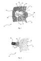
- One in the Fig. 1 to Fig. 4 Wholly or partially illustrated lighting chamber 01 of a motor vehicle light designed for example as a taillight has at least one reflector 02 and at least one light source 03 with at least one light source 04.
- the at least one reflector 02 together with the at least one light source 04 comprising at least one light source 03 can be accommodated in a luminaire interior of a motor vehicle luminaire enclosed by a luminaire housing, not shown in detail, and a transparent, preferably clear and colorless lens.
- a colored lens is preferably used for color filtering.
- At least one recess 05 is provided as a lamp hole for at least one light source 04 of the luminous means 03.
- the luminaire chamber 01 comprises a surface which covers the area which has been removed from the reflector 02 by the recess 05 and which covers the structure of the reflector 02, which preferably surrounds the recess 05, and which simulates the cover plate 06.
- the at least one light source 04 is overlooking the in the Fig. 1 to Fig. 4 the observer and the lens of the motor vehicle light facing front 07 of the reflector 02, for example, in the direction of a local surface normal one through the Seen recess 05 formed surface, arranged behind the Abdeckblende 06, so that the Abdeckblende 06 denied the view of the recess formed by the recess 05 lamp hole and the at least one light source 04, whereby the light source 04 and the lamp hole or the recess 05 through the lens Seen behind the light disk off and the recess 05 facing back 11 of the cover 06 are arranged and thereby protected from direct glances or hidden.
- the luminaire chamber 01 is characterized by an adjustability or adjustment of the beam path of the light emitted by the at least one light source 04 into the reflector 02 in or between at least two beam paths.
- at least one first beam path is provided in a first state of the lamp chamber 01 to fulfill a first light function
- Based on the different beam paths at least two arbitrary light functions of the motor vehicle lamp of the same or different light color and / or the same or different emission characteristics can be realized by means of only one lamp chamber 01.
- the reflector 02 surrounding the recess 05 reflects the light radiated into it in the different beam paths, for example from at least one light source 04, past the cover panel 06 and out of the lamp compartment 01 through the lens of the motor vehicle light.
- the first beam path can be designed such that a focused radiation characteristic is obtained, whereas the second beam path can be designed such that a defocused radiation characteristic is obtained.
- the at least one light source 04 along one or in the direction indicated by double arrows trajectory B relative to the recess 05 surrounding reflector 02 at least between two different, at least two different states of the lamp chamber 01 corresponding and with different beam paths associated positions be arranged movably.
- the motor vehicle light is hereafter characterized by a relative adjustability of the at least one light source in at least two corresponding to the at least two states of the lamp chamber 01 different positions relative to the Recess 05 surrounding reflector 02 for adjusting the beam path between at least two different beam paths.
- different beam positions of the at least one light source 04 to the focal point of the reflector 02 result in different beam paths accompanied by different emission characteristics having different light and luminance distributions.
- the first beam path for example in the first position of the at least one light source 04 relative to the reflector 02, at least one light source 04 is at least a first light function sufficient light and luminance distribution of a first radiation characteristic obtained.
- the second beam path for example in the second position of the at least one light source 04 relative to the reflector, at least one light source 04 is at least a second light function sufficient light and luminance distribution of a second radiation characteristic obtained.
- the at least one light source 04 may be, for example, one or more LEDs 12 (FIG. Fig. 4 ) or one or more incandescent filaments 17 of a light source 03 designed as an incandescent lamp.
- the at least one light source 04 protrudes in the first state and / or in the second state of the lamp chamber 01 on the front side 07 of the reflector 02 via the surface formed by the recess 05 delimited by the reflector 02 or via the recess 05 delimiting it It is also conceivable that the at least one light source 04 in the first or second state is still behind the back 10 of the reflector 02 in the lamp hole formed by the recess 05.
- a primary reflector may be mounted, which directs the light on the reflector 02 and then steers out of the light.
- the cover panel 06 may be arranged to be movable relative to the reflector 02 together with the light source 04 or independently thereof in the direction of the movement path B.
- the light source 04 can be mechanically fastened to the cover panel 06 and arranged in an electrically contacted manner, so that only a facial expression is required for the relative movement between the reflector 02 and the cover panel 06.
- the at least one light source 04 can be mechanically fastened to the light disc and the recess 02 surrounding the reflector 02 facing back 11 of the cover plate 06 and electrically contacted.
- a relative adjustability of the at least one light source 04 is provided in at least two different positions with respect to the reflector 02 surrounding the recess 05, a joint adjustment of As already mentioned, only one facial expression for a relative movement between the reflector 02 required for obtaining different beam paths and the at least one together with the cover panel 06 relative to the recess 05 surrounding reflector 02 movably arranged light source 04 required.
- At least the cover panel 06 may, for example, together with the at least one light source 04 or independently of this along a trajectory B, preferably in the direction of a local surface normal of a surface formed by the recess 05 at least between a first hot state with the light source 04 corresponding first state of the lamp chamber 01, in which a first beam path is present and the lamp chamber 01 fulfills a first light function with a first light color and a first emission characteristic, and a second state of the lamp chamber 01 corresponding to a second hot state with the light source switched on, in which a second beam path exists and the lamp chamber 01 a second light function having a second light color and a second emission characteristic, be arranged to be movable relative to the reflector 02 in order to generate the different beam paths.
- the same or different light sources 04 of the luminous means 03 can be active in the first and in the second hot state.
- the first and second light colors may be identical or different.
- one or more light sources 04 may be provided which emit light of the same or different light color.
- first and the second radiation characteristics can be the same or be different.
- At least the cover panel 06 can along or in the direction indicated by double arrows trajectory B at least between a in Fig. 1 and Fig. 3 illustrated warm state of the lamp chamber 01 with the light source 03 corresponding first and / or second state and a in Fig. 2 illustrated cold state of the lamp chamber 01 with the light source 03 off corresponding third state relative to the reflector 02 to be movably arranged.
- the recess 05 in the reflector 02 preferably flush or, for example, adjacent to a recess 05 surrounding edge 08 of the reflector 02, the recess 05 overlapping.
- first or second state of the lamp chamber 01 are the Abdeckblende 06, the recess 05 in contrast free and located in the Fig. 1, Fig. 2 .
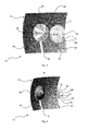
- FIG. 3 and FIG. 4 shown view of the front of the front 07 of the reflector 02 in front of the reflector 02 limited recess 05th
- Fig. 4 in this case shows the same view with a view of the front 07 of the reflector 02 as Fig. 3 , wherein the cover panel 06 is removed for clarity, in order to explain the construction of the lamp chamber 01 the view on or behind the Abdeckblende 06 arranged there preferably mechanically fixed and electrically contacted light sources 04 of a lamp 03 of the lamp chamber 01 free.
- the movement path B can run at least in sections along a straight line comprising a local surface normal of a surface formed by the recess 06.
- the trajectory B is a distance along a straight line comprising a local surface normal of a surface formed by the recess 06.
- the cover panel 06 may be formed corresponding to the recess 05.
- the Abdeckblende 06 as in Fig. 1 represented the recess 05 in the form, function and appearance of the reflector 02 simulate. This is in the in Fig. 2 illustrated third state neither the recess 05, nor the Abdeckblende 06th recognizable. For the viewer, the impression of a completely homogeneous, lamp hole and light source-free reflector 02 results.
- the Abdeckblende 06 can in in Fig. 2 illustrated, the cold state corresponding third state, the recess 05 cover in two ways.
- the cover plate 06 Apart from the required tolerances and gaps, which are necessary that the cover plate 06 can retract into the recess 05 to complete flush with the front 07 of the reflector 02, while the Abdeckblende 06 has a limiting by the recess 05 and surrounding this Edge 08 of the reflector 02 formed outer contour in terms of geometry and dimensions identical shape.
- the Abdeckblende 06 in the in Fig. 2 illustrated third state to the recess 05 surrounding reflector 02 rest on the front of the lens facing the lens 07 and thereby overlap the recess 05 surrounding edge 08 of the reflector 02.
- the cover panel 06 does not close around the recess 05 around flush with the front 07 of the reflector 02 from.
- For the production is simplified because the overlapping allows tolerance compensation.
- the lighting chamber 01 can also be as in FIG. 3 and FIG. 4 represented a primary reflector 09 include.
- the primary reflector 09 is arranged at least partially and / or at least temporarily in the recess 05. Alternatively or additionally, the primary reflector at least partially and / or at least temporarily occupies the lamp hole formed by the recess 05.
- the at least one light source 04 is arranged between the cover panel 06 and the primary reflector 09.
- the primary reflector 09 reflects light radiated from the at least one light source 04 in the direction of the recess 05 into the reflector 02 surrounding the recess 05 and / or directly from the lamp chamber 01, for example through the lens of the motor vehicle light, while maintaining a predetermined emission characteristic.
- the primary reflector 09 can be used to obtain or generate different beam paths together with or independently of the cover panel 06 and / or the at least one light source 04 at least between two different, at least two different states of the lamp chamber 01 corresponding positions relative to the recess 05 surrounding reflector 02 to be movably arranged.
- the primary reflector 09 in the first and / or second state of the luminaire chamber preferably either ends flush with the reflector 02 surrounding the recess 05 or its front side 07, or lies, for example, against the reflector 02 surrounding the recess 05 its rear side facing away from the lens 10 and thereby overlaps the recess 05 surrounding edge 08 of the reflector 02nd
- the primary reflector 09 In the first and / or second state, the primary reflector 09 preferably at least partially accommodates the recess 05 and preferably ends flush with the reflector 02 surrounding the recess 05. If the primary reflector 09 in the second state is flush with the reflector 02 surrounding the recess 05, in the first state the primary reflector 09 can be seen from the cover panel 06 in front of or behind the reflector 02 surrounding the recess 05.
- the primary reflector 09 in the second state can abut the reflector 02 surrounding the recess 05 on the rear side 10 facing away from the lens or on the front side 07 facing the lens, thereby overlapping a rim 08 of the reflector 02 surrounding the recess 05, depending on whether the primary reflector 09 is in the first state behind or in front of the reflector 02 surrounding the recess 05.
- the cover plate 06 may be provided on its side facing the viewer 02 and the recess 05 facing the rear side 11 with a secondary reflector which reflects on the back 11 of the cover 06 radiated light in the recess 05 surrounding the reflector 02. If, for example, the at least one light source 04 is arranged immovably relative to the cover panel 06 or the reflector 02, then a change in the beam path can be achieved by a relative movement between cover panel 06 and the reflector 05 surrounding the recess 05.
- a secondary reflector may be provided on the rear side facing away from the lens 11 of the cover 06, for example by the Abdeckblende 06 on its side facing away from the lens 11 with a such secondary reflector is provided, for example, in the form of a secondary reflector structure formed there and, for example, mirrored, or by arranging such a secondary reflector on the rear side 11 of the cover panel 06.
- the secondary reflector and, in the case of a fixed arrangement of the secondary reflector on the rear side 11 of the cover panel 06, if appropriate also the cover panel 06, can receive at least two different, at least two, different states of the luminaire chamber in order to obtain different beam paths along a movement path B relative to the reflector 02 surrounding the recess 05 01 corresponding positions to be arranged movable.
- the secondary reflector can be arranged, for example, rigidly or along a trajectory B between two or more positions adjustable on the back 11 of the cover panel 06.
- a particularly high variance of possible different beam paths, accompanied by a particularly high efficiency of the optical system of the lamp chamber 01 results from an adjustably arranged primary reflector 09 in conjunction with a recess 11 surrounding the recess 05 facing the rear side 11 of the preferably also adjustably arranged Abdeckblende 06 arranged secondary reflector, so that by multiple reflection at the primary reflector 09, the arranged on the Abdeckblende 06 secondary reflector or the reflector 05 surrounding the recess 02 a radiation pattern at the exit from the lens of the motor vehicle light is obtained which the legal requirements for a light function of a Motor vehicle lamp with respect to luminance distribution in one or more preferred directions complies.
- Primary reflector 09 and secondary reflector or cover plate 06 can be arranged together and / or independently, for example relative to the recess 05 surrounding reflector 02 and / or at least one light source 04 to be adjustable to obtain different beam paths.
- the particularly high efficiency of the optical system can be explained inter alia by the fact that the primary reflector 09, which occupies the recess at least partially in one state, does not waste light through the lamp hole formed by the recess 05 behind the reflector 02 surrounding the recess 05.
- mirror optics for a light function such as a side marker light function, which is effective only in one state of the luminaire chamber 01 or in only one relative position or in only one beam path, can be provided on the rear side 11 of the cover panel 06.
- the effectiveness in a beam path is characterized in that in this state, a desired, for example legally prescribed light distribution of the light function is met.
- At least one LED 12 may be as in Fig. 4 represented as at least one light source 04 may be provided at least one lamp 03 of the lamp chamber 01.
- LEDs 12 as light sources 04 can be dispensed with a color filter by a colored lens, as required for example in incandescent lamps.
- LEDs 12 When using LEDs 12, such a coloring of the lens is not required. As a result, with the use of LEDs 12 and colorless lenses are used because no color filtering is required. In this case, costs can be saved at the same time, as can be completely dispensed with the red cycle during plastic injection of the lens.
- a plurality of identically or differently colored LEDs 12 may be provided as light sources 04 of a luminous means 03, for example by several light functions, for example of different brightness and / or different color, in one and the same Luminaire chamber to bring the lamp chamber 01 under.
- the light source 03 may include at least one light exit area having at least one light guide, in which light is coupled in at least one of the light coupling surface of a Lichteinkoppel Schemes different in a first or second state of the lamp chamber 01 hot state.
- the Abdeckblende 06 can as in Fig. 3 shown on its front side facing the lens 13 may be provided with at least one graphic 14.
- the graphic 14 may, for example, be raised or recessed in relief or flush with the front surface 13 of the cover panel 06.
- the graphic 14 can be one or more images and / or drawings and / or graphic representations and / or logos and / or characters, such as letters and / or numbers, etc., or one or more combinations thereof, such as for example, a brand emblem, to enumerate only a few conceivable embodiments of graphics.
- the Abdeckblende 06 can as in Fig. 2 illustrated comprise a web 15 which may correspond to a corresponding portion 16 of the recess 05.
- the web 15 may serve the optionally provided movable arrangement of the Abdeckblende 06, for example by attachment to a movement along the trajectory B executive mimic.
- the web 15 of the lamination of a possibly provided electrical contacting of the light source 04 of a lamp 03 serve, such as provided as light sources 04 and mechanically fixed to the Abdeckblende 06 and electrically contacted LEDs 12.
- the web 15 is not shown for clarity, as well as in Fig. 4 in which the entire cover panel 06 is not shown in order to show the LEDs 12 provided there as light sources 04.
- the lamp interior of a motor vehicle light described above can be subdivided into one or more lamp chambers 01, of which at least one lamp chamber 01 comprises a previously described reflector 02 together with at least one light source 04, the beam path of the from the at least one light source 04 outgoing light between at least two different, serving to fulfill various light functions beam paths is adjustable.
- the invention is particularly industrially applicable in the field of production of motor vehicle lights.
Abstract
Description
Die Erfindung betrifft eine Kraftfahrzeugleuchte gemäß dem Oberbegriff des Anspruchs 1.The invention relates to a motor vehicle lamp according to the preamble of claim 1.
Eine Kraftfahrzeugleuchte umfasst im Wesentlichen einen von einem Leuchtengehäuse und einer Lichtscheibe umschlossenen Leuchteninnenraum und mindestens ein darin beherbergtes Leuchtmittel für wenigstens eine Lichtfunktion der Kraftfahrzeugleuchte. In dem Leuchteninnenraum kann mindestens ein hinter wenigstens einer Lichtquelle des zumindest einen Leuchtmittels angeordneter Reflektor untergebracht sein. Der Reflektor kann zumindest zum Teil durch ein separates Bauteil und/oder durch wenigstens einen Teil des Leuchtengehäuse selbst, beispielsweise vermittels einer zumindest teilweisen reflektierenden Beschichtung, gebildet sein.A motor vehicle lamp essentially comprises a lamp housing enclosed by a lamp housing and a lens, and at least one lamp housed therein for at least one light function of the motor vehicle lamp. At least one reflector arranged behind at least one light source of the at least one luminous means can be accommodated in the luminaire interior. The reflector can be formed at least in part by a separate component and / or by at least one part of the luminaire housing itself, for example by means of an at least partially reflective coating.
Wenigstens einer Lichtquelle des Leuchtmittels können ein oder mehrere Optikelemente, wie etwa mindestens eine Linse, mindestens ein Rinnenkonzentrator, z.B. mindestens eine Parabolrinne (CPC; Compound Parabolic Concentrator) oder dergleichen zur Ausformung einer definierten Abstrahlcharakteristik zugeordnet sein.At least one light source of the illuminant may comprise one or more optical elements, such as at least one lens, at least one channel concentrator, e.g. at least one parabolic trough (CPC) or the like for forming a defined emission characteristic.
Die Lichtscheibe ist durch eine transparente Abdeckung gebildet, welche den Leuchteninnenraum sowie die von diesem beherbergten Bauteile gegen Witterungseinflüsse schützt.The lens is formed by a transparent cover, which protects the interior of the lamp and the components housed by this against the weather.
In dem Leuchteninnenraum kann im Strahlengang zwischen wenigstens einer Lichtquelle des Leuchtmittels und der Lichtscheibe wenigstens eine Optikscheibe angeordnet sein, welche beispielsweise eine bestimmte Struktur und/oder Maskierung aufweisen kann, etwa um bei einer klaren, beispielsweise für einen Betrachter eine Tiefenwirkung bewirkenden Lichtscheibe das Leuchtmittel und/oder dessen mindestens eine Lichtquelle zu kaschieren. Das Leuchtengehäuse bzw. der Leuchteninnenraum kann in mehrere Leuchtenkammern mit jeweils eigenen Lichtquellen und/oder Leuchtmitteln, eventuell Reflektoren und/oder Optikelementen und/oder Optikscheiben, sowie gegebenenfalls Lichtscheiben unterteilt sein, von denen mehrere oder alle Leuchtenkammern gleiche oder jede Leuchtenkammer eine andere Lichtfunktionen erfüllen kann.In the luminaire interior, at least one optical disk can be arranged in the beam path between at least one light source of the luminous means and the light disk, which can have a specific structure and / or masking, for example, with a clear lens, for example a light effect for a viewer, the luminous means and / or its at least one light source to conceal. The luminaire housing or the interior of the luminaire can be subdivided into a plurality of luminaire chambers, each with its own light sources and / or illuminants, possibly reflectors and / or optical elements and / or optical disks, as well as optionally light disks, of which several or all lamp chambers same or each lamp chamber fulfill a different lighting function can.
Bei einer Lichtfunktion handelt es sich dabei um eine zur Erfüllung einer Aufgabe vorgesehene Funktion der Kraftfahrzeugleuchte. Jede Kraftfahrzeugleuchte erfüllt je nach Ausgestaltung eine oder mehrere Aufgaben bzw. Funktionen. Zur Erfüllung jeder Aufgabe bzw. Funktion ist eine Lichtfunktion der Kraftfahrzeugleuchte vorgesehen. Lichtfunktionen sind beispielsweise bei einer Ausgestaltung als Scheinwerfer eine die Fahrbahn ausleuchtende Funktion, oder bei einer Ausgestaltung als Signalleuchte eine Signalfunktion, wie beispielsweise eine Wiederholblinklichtfunktion zur Fahrtrichtungsanzeige oder eine Bremslichtfunktion zur Anzeige einer Bremstätigkeit, oder z.B. einer Begrenzungslichtfunktion, wie etwa einer Schlusslicht- oder Rücklichtfunktion, zur Sicherstellung einer Sichtbarkeit des Kraftfahrzeugs bei Tag und/oder Nacht, wie etwa bei einer Ausgestaltung als Heckleuchte oder Tagfahrleuchte. Beispiele für Kraftfahrzeugleuchten sind am Fahrzeugbug, an den Fahrzeugflanken und/oder an den Seitenspiegeln sowie am Fahrzeugheck angeordnete Wiederholblinkleuchten, Ausstiegsleuchten, beispielsweise zur Umfeldbeleuchtung, Begrenzungsleuchten, Bremsleuchten, Nebelleuchten, Rückfahrleuchten, sowie typischerweise hoch gesetzte dritte Bremsleuchten, so genannte Central, High-Mounted Braking Lights, Tagfahrleuchten, Scheinwerfer und auch als Abbiege- oder Kurvenlicht verwendete Nebelscheinwerfer, sowie Kombinationen hiervon.A light function is a function of the motor vehicle light intended to fulfill a task. Each motor vehicle light fulfills one or more tasks or functions depending on the design. To fulfill each task or function, a light function of the motor vehicle light is provided. Light functions are, for example, in a configuration as a headlamp a function illuminating the road surface, or in a configuration as a signal light, a signal function, such as a Wiederblinklichtfunktion to the direction indicator or a brake light function to indicate a braking action, or. a limiting light function, such as a taillight or taillight function, to ensure visibility of the motor vehicle during the day and / or night, such as in a taillight or daytime running light configuration. Examples of motor vehicle lights are the Fahrzeugbug, on the vehicle flanks and / or on the side mirrors and arranged at the rear of vehicle rear lights, exit lights, for example, ambient lighting, marker lights, brake lights, fog lamps, reversing lights, and typically high set third brake lights, so-called Central, High-Mounted Braking lights, daytime running lights, headlamps and fog lights used as turning or cornering lights, as well as combinations thereof.
Ein Leuchtmittel für wenigstens eine Lichtfunktion umfasst zumindest wenigstens eine Lichtquelle, beispielsweise mindestens eine Glühlampe oder mindestens eine Gasentladungslampe oder mindestens eine Leuchtdiode sowie gegebenenfalls Kombinationen hiervon.A luminous means for at least one light function comprises at least at least one light source, for example at least one incandescent lamp or at least one gas discharge lamp or at least one light-emitting diode and optionally combinations thereof.
Beispielsweise kommen als Lichtquellen von Leuchtmitteln für Kraftfahrzeugleuchten unter anderem wegen ihres geringen Stromverbrauchs vermehrt Leuchtdioden zum Einsatz. Diese bestehen aus mindestens einem Lichtemittierende-Diode-Halbleiter-Chip, kurz LED-Chip, sowie wenigstens einer beispielsweise durch Spritzgießen angeformten, den mindestens einen LED-Chip ganz oder teilweise umhüllenden Primäroptik. Auch sind Kraftfahrzeugleuchten bekannt, in denen reine LED-Chips ohne angeformte Primäroptiken zum Einsatz kommen. Im Folgenden wird deshalb der Einfachheit halber nicht mehr zwischen Leuchtdiode und LED-Chip unterschieden und statt dessen einheitlich der Begriff LED stellvertretend für beide Ausgestaltungen verwendet, es sei denn, es ist explizit etwas anderes erwähnt. Herausragende Eigenschaften von LEDs im Vergleich zu anderen, konventionellen Lichtquellen von Leuchtmitteln sind eine wesentlich längere Lebensdauer und eine wesentlich höhere Lichtausbeute bei gleicher Leistungsaufnahme. Dadurch und unter anderem auch wegen ihrer kompakteren Abmessungen können durch Verwendung von LEDs als Lichtquelle von Leuchtmitteln Kraftfahrzeugleuchten verwirklicht werden, die an fast jede nur erdenkliche Einbausituation angepasst sein können.For example, come as light sources of lamps for automotive lighting, inter alia, because of their low power consumption LEDs increasingly used. These consist of at least one light-emitting diode semiconductor chip, short LED chip, as well as at least one, for example, molded by injection molding, the at least one LED chip completely or partially enveloping primary optics. Also, automotive lights are known in which pure LED chips are used without molded primary optics. In the following, therefore, for the sake of simplicity, no distinction is made between light-emitting diode and LED chip and, instead, the term LED is used uniformly for both embodiments, unless explicitly stated otherwise. Outstanding properties of LEDs compared to other, conventional light sources of Lamps are a much longer life and a much higher light output with the same power consumption. As a result, and among other things also because of their more compact dimensions can be realized by using LEDs as the light source of lamps automotive lights that can be adapted to almost every imaginable installation situation.
Eine typische Anpassung an die Einbausituation betrifft die äußere Gestalt der Kraftfahrzeugleuchte. Diese äußere Gestalt der Kraftfahrzeugleuchte ist beispielsweise durch die gestalterische Formgebung eines Kraftfahrzeugs sowie durch die vorgesehene Kontur der Kraftfahrzeugleuchte vorgegeben und spiegelt sich im so genannten Strakverlauf der Kraftfahrzeugleuchte wider.A typical adaptation to the installation situation relates to the external shape of the motor vehicle light. This external shape of the motor vehicle light is predetermined, for example, by the design of a motor vehicle and by the intended contour of the motor vehicle light and is reflected in the so-called strak curve of the motor vehicle light.
Eine weitere typische Anpassung einer Kraftfahrzeugleuchte an die Einbausituation betrifft den zur Verfügung stehenden Bauraum. Dabei wird ein möglichst geringer Bauraumbedarf angestrebt, beispielsweise um bei einer Ausgestaltung einer Kraftfahrzeugleuchte als Heckleuchte mehr Platz für den Kofferraum eines Kraftfahrzeugs zur Verfügung zu haben und um gleichzeitig Material und Gewicht zu sparen, wodurch beispielsweise Verbrauchseinsparungen von Treibstoff einhergehend mit einer Verringerung der Umweltbelastung sowohl bei der Herstellung, als auch im Betrieb des Kraftfahrzeugs erreicht werden können.Another typical adaptation of a motor vehicle light to the installation situation relates to the available space. In this case, the smallest possible space requirement is sought, for example, to have more space for the trunk of a motor vehicle available in an embodiment of a motor vehicle light as tail light and at the same time to save material and weight, which, for example, fuel savings of fuel associated with a reduction in environmental impact both at the production, as well as in the operation of the motor vehicle can be achieved.
Um möglichst wenig Bauraum zu beanspruchen ist bekannt, mehrere Lichtfunktionen in einer Leuchtenkammer einer Kraftfahrzeugleuchte unterzubringen.To claim as little space is known to accommodate several lighting functions in a lighting chamber of a motor vehicle light.
Bislang sind hierzu verschiedene und/oder unterschiedlich stark bestromte Lichtquellen gleicher oder unterschiedlicher Lichtfarbe vorgesehen, vorausgesetzt, die zu verwirklichenden Lichtfunktionen weisen die gleichen oder zumindest stark ähnlichen Abstrahlcharakteristika auf. Die Abstrahlcharakteristik einer Lichtfunktion zeichnet sich dabei durch eine die gesetzlichen Vorgaben an eine Lichtfunktion einer Kraftfahrzeugleuchte einhaltende Leuchtdichteverteilung in einer oder mehreren Vorzugsrichtungen aus. Daraus folgt, dass nach dem Stand der Technik zur Verwirklichung mehrerer Lichtfunktionen in einer Leuchtenkammer die an die zu verwirklichenden Lichtfunktionen gestellten gesetzlichen Anforderungen an die Sichtbarkeit und Lichtverteilung sowie Leuchtdichteverteilung identisch oder zumindest stark ähnlich sein müssen.To this end, different and / or differently energized light sources of the same or different light color are provided, provided that the light functions to be realized have the same or at least strongly similar emission characteristics. The emission characteristic of a light function is distinguished by a luminance distribution in one or more preferred directions that complies with the legal requirements for a light function of a motor vehicle light. It follows that according to the prior art for the realization of several light functions in a lighting chamber, the legal requirements placed on the light functions to be realized on the visibility and light distribution and luminance distribution must be identical or at least strongly similar.
Neben der Anpassung an die Einbausituation müssen Kraftfahrzeugleuchten sehr hohe Qualitätsanforderungen erfüllen. So werden beispielsweise bereits geringe Abweichungen von einem homogenen Eindruck beispielsweise des Gesamtbilds und/oder der Ausleuchtung beispielsweise einer Leuchtenkammer, wie beispielsweise ein dunkel erscheinendes Lampenloch und/oder ein möglicherweise blendender direkter Blick des Betrachters auf die Lichtquelle eines Leuchtmittels als qualitätsmindernd angesehen.In addition to the adaptation to the installation situation, automotive lights must be very meet high quality requirements. Thus, for example, even slight deviations from a homogeneous impression of, for example, the overall image and / or the illumination, for example, of a luminaire chamber, such as a dark-appearing lamp hole and / or a possibly dazzling direct view of the viewer on the light source of a luminous means, are considered to reduce the quality.
Um den hohen Qualitätsanforderungen an Kraftfahrzeugleuchten gerecht zu werden, ist ein Ziel bei der Entwicklung von Kraftfahrzeugleuchten, das oder die Lichtquellen einer oder mehrerer Lichtfunktionen einer Kraftfahrzeugleuchte vor dem direkten Blick eines Betrachters zu verbergen.In order to meet the high quality requirements of automotive lights, a goal in the development of automotive lights is to hide the light sources of one or more light functions of a motor vehicle light from the direct view of a viewer.
Um eine oder mehrere, ihr Licht in einen oder mehrere Reflektoren strahlende Lichtquellen eines Leuchtmittels dem Blick des Betrachters zu entziehen, welches Licht mittels Reflexion an entsprechenden Formen bzw. Reflektorstrukturen auf dem Reflektor, wie etwa Kissen, Walzen, etc., in die gewünschte Richtung gelenkt wird, ist bekannt, die Lichtquelle beispielsweise oberhalb oder unterhalb des Reflektors oder neben diesem anzuordnen und das von ihr abgestrahlte Licht seitlich in einen Reflektor einzustrahlen. Hierdurch ist die Lichtquelle für den Betrachter beim direkten Blick aus normaler Richtung, wie dies der Sicht eines anderen Verkehrsteilnehmers bei in ein Kraftfahrzeug eingebautem Zustand entspricht, auf die Kraftfahrzeugleuchte nicht erkennbar. Diese wird erst sichtbar, sobald der Betrachter von oben oder unten her in die Kraftfahrzeugleuchte blickt. Da dies tatsächlich eher selten vorkommt, können Lichtquellen auf diese Art gut verborgen werden und der Reflektor weitestgehend lampenlochfrei gehalten werden.In order to extract one or more light sources of a luminous means, which emit their light into one or more reflectors, from the view of the observer, which light is reflected into corresponding shapes or reflector structures on the reflector, such as cushions, rollers, etc., in the desired direction is directed, it is known to arrange the light source, for example, above or below the reflector or next to this and radiate the light emitted by it laterally in a reflector. As a result, the light source for the viewer when looking directly from the normal direction, as corresponds to the view of another road user when installed in a motor vehicle state, not recognizable on the vehicle light. This is visible only when the viewer looks from above or below in the vehicle light. Since this is actually rare, light sources can be well hidden in this way and the reflector are kept as free of bulbs as possible.
Aufgrund der meist starken Strakverläufe ist es nicht immer möglich die Lichtquellen in einer lichttechnisch günstigen Lage, wie etwa direkt abstrahlend oder von oben oder unten her in den Reflektor einstrahlend einzubinden. Zum anderen kann hierdurch unabhängig vom Strakverlauf nicht vollständig sichergestellt werden, dass dadurch ein direkter Blick auf die Lichtquelle von außen durch die Lichtscheibe hindurch vollständig verwehrt ist.Due to the mostly strong Strakverläufe, it is not always possible the light sources in a photometrically favorable location, such as directly radiating or integrating from above or below in the reflector einstrahlend. On the other hand, this can not be completely ensured regardless of the Strakverlauf that thereby a direct view of the light source from the outside through the lens is completely denied.
So kommt es insbesondere bei starken Strakverläufen vor, dass die Lichtquellen bei der Betrachtung von außerhalb der Kraftfahrzeugleuchte durch die Lichtscheibe hindurch teilweise sichtbar sind. Eine zumindest aus einigen Blickwinkeln von außerhalb der Kraftfahrzeugleuchte durch die Lichtscheibe hindurch sichtbare Lichtquelle eines zur Erfüllung einer Lichtfunktion vorgesehenen Leuchtmittels wird als störend und den Qualitätseindruck nachhaltig negativ beeinflussend empfundenen.Thus, it is especially in strong Strakverläufen that the light sources are partially visible when viewed from outside the motor vehicle light through the lens. An at least from some angles from outside the motor vehicle light through the lens visible through the light source of a light function provided for illuminating means is disturbing and the Perceived quality impression sustainably negatively influencing.
Ein vollständiges Verbergen der Lichtquellen ist erst z. B. mittels auch als Lichtleiter bezeichneter, totalreflektierender (TIR; Total Internal Reflection), lichtleitender Elemente mit einem Lichteinkoppelbereich und einem Lichtauskoppelbereich möglich, die das in sie am Lichteinkoppelbereich eingekoppelte Licht von einer verborgen angeordneten Lichtquelle in Richtung Auskoppelbereich leiten und dort wieder auskoppeln. Das ausgekoppelte Licht kann dabei direkt, ohne einen Reflektor in der gewünschten Richtung abgestrahlt werden, oder indirekt, indem es in einen Reflektor eingestrahlt wird, der es dann in die gewünschte Richtung reflektiert.A complete concealment of the light sources is only z. B. by means also referred to as a light guide, total internal reflection (TIR), light-conducting elements with a Lichteinkoppelbereich and a Lichtauskoppelbereich possible, which guide the light coupled into it at Lichteinkoppelbereich light from a hidden light source in the direction Auskoppelbereich and decouple there again. The decoupled light can be emitted directly without a reflector in the desired direction, or indirectly by being irradiated in a reflector, which then reflects it in the desired direction.
Bei einer Kraftfahrzeugleuchte können ein oder mehrere Lichtleiter vorgesehen sein, beispielsweise um eine gewünschte Lichtverteilung z.B. über die Lichtscheibe hinweg des von einer oder mehreren Lichtquellen ausgestrahlten Lichts zu erhalten.In a motor vehicle light, one or more optical fibers may be provided, for example to provide a desired light distribution e.g. across the lens of the light emitted by one or more light sources.
Ein Lichtleiter, in den Licht mindestens einer Lichtquelle an mindestens einer Lichteinkoppelfläche des Lichteinkoppelbereichs ein- und an mindestens einer von der Lichteinkoppelfläche verschiedenen Lichtauskoppelfläche des Lichtauskoppelbereichs wieder ausgekoppelt wird, kann dabei als ein separates Bauteil im Leuchteninnenraum beherbergt oder Teil eines Leuchtmittels sein.An optical waveguide into which light of at least one light source is coupled at at least one light input surface of the light coupling region and coupled back to at least one light outcoupling surface of the light outcoupling region that is different from the light coupling surface can be accommodated as a separate component in the interior of the luminaire or be part of a light source.
Beispielsweise kann ein Leuchtmittel einen oder mehrere Lichtleiter sowie eine oder mehrere, das von ihnen ausgestrahlte Licht zumindest zum Teil in den wenigstens einen Lichtleiter einkoppelnde Lichtquellen umfassen. Ein Lichtleiter eines solchen Leuchtmittels kann beispielsweise als Primäroptik einer oder mehrerer LEDs dienen bzw. als eine solche Primäroptik ausgebildet sein.By way of example, a luminous means may comprise one or more light guides and one or more light sources emitting light from them, at least in part into the light sources coupling in at least one light guide. An optical waveguide of such a luminous means can serve, for example, as a primary optic of one or more LEDs or be designed as such a primary optic.
Der Lichtleiter kann beispielsweise stabförmig als so genannter Stablichtleiter und/oder flächig als so genannter Flächenlichtleiter ausgebildet sein, mit einer auf seiner beispielsweise normal zur Hauptabstrahlrichtung einer Kraftfahrzeugleuchte orientierten Vorderseite angeordneten Lichtauskoppelfläche.The optical waveguide can be configured, for example, in the form of a bar as a so-called bar light guide and / or as a so-called planar light guide, with a light output surface arranged on its front side oriented, for example, normal to the main emission direction of a motor vehicle light.
Nachteilig an Lichtleitern ist deren kostspieliger und hoher Entwicklungs- und Herstellungsaufwand. Ein weiterer Nachteil ist, dass ein insbesondere einem starken Strakverlauf angepasster Lichtleiter eine inhomogene Ausleuchtung durch das in ihn eingekoppelte Licht erfährt, was wiederum als qualitätsmindernd empfunden wird.A disadvantage of optical fibers is their costly and high development and production costs. Another disadvantage is that a particular adapted to a strong Strakverlauf light guide undergoes an inhomogeneous illumination by the light coupled into it, which in turn is perceived as a quality-reducing.
Um einen direkten Blick auf eine im eingeschalteten Zustand eine erhebliche Blendwirkung darstellende Lichtquelle eines Leuchtmittels zu verhindern sind darüber hinaus Blenden bekannt, welche von außen durch die Lichtscheibe hindurch gesehen vor der durch ein Lampenloch im Reflektor in eine Leuchtenkammer ragenden Lichtquelle angeordnet sind.In order to prevent a direct view of a significant dazzling effect performing light source of a light source in the on state are also known screens, which are seen from the outside through the lens through before the protruding through a lamp hole in the reflector in a lamp chamber light source.
Durch
Nachteilig hieran ist der hohe Bedarf an Bautiefe hinter und vor dem Reflektor. Ein weiterer Nachteil hieran ist, dass die Lichtaustrittsöffnung dabei nur einen geringen Teil der Ansichtsfläche der Kraftfahrzeugleuchte aus Richtung des aus der Austrittsöffnung austretenden Lichts einnimmt.The disadvantage of this is the high demand for construction depth behind and in front of the reflector. Another disadvantage of this is that the light exit opening occupies only a small part of the viewing surface of the motor vehicle lamp from the direction of emerging from the outlet opening light.
Eine weitere Möglichkeit, den direkten Blick auf eine Lichtquelle einer Kraftfahrzeugleuchte zu verwehren ist die Verwendung einer zwischen Lichtquelle und Lichtscheibe angeordneten, strukturierten Optikscheibe.A further possibility to deny the direct view of a light source of a motor vehicle light is the use of a arranged between the light source and the lens, structured optical disc.
Nachteilig hieran ist die Verringerung der Güte des optischen Systems, da die Optikscheibe einen Teil des von der Lichtquelle abgestrahlten Lichts absorbiert und/oder zurück reflektiert und darüber hinaus zumindest zum Teil diffus streut, wodurch eine höhere Lichtleistung erforderlich ist, um beispielsweise gesetzlich vorgegebene Werte einer Leuchtdichteverteilung in einer oder mehreren Vorzugsrichtungen einzuhalten. Damit einhergehend wird hierdurch ein zur Stromversorgung vorgesehenes Bordnetz eines Kraftfahrzeugs stärker belastet, weil insgesamt ein höherer Lichtstrom benötigt wird.A disadvantage of this is the reduction of the quality of the optical system, since the optical disc absorbs a part of the light emitted from the light source and / or reflected back and beyond scattered at least partially diffuse, whereby a higher light output is required, for example, legally prescribed values Compliance with luminance distribution in one or more preferred directions. As a result, an on-board network of a motor vehicle provided for the power supply is thereby subjected to a greater load, because altogether a higher luminous flux is required.
Der Erfindung liegt die Aufgabe zu Grunde, ein Kraftfahrzeugleuchte zu entwickeln, welche bei geringem Bauraumbedarf mehrere Lichtfunktionen gleicher oder unterschiedlicher Lichtfarbe und/oder gleicher oder unterschiedlicher Abstrahlcharakteristik mit nur einer Leuchtenkammer zu erfüllen in der Lage ist bzw. die Ausführung mehrerer verschiedener Lichtfunktionen in nur einer Leuchtenkammer erlaubt und bei der im auch als Warmzustand bezeichneten eingeschalteten Zustand des Leuchtmittels ein direkter Blick auf ein zur Erfüllung mindestens einer Lichtfunktion der Kraftfahrzeugleuchte vorgesehenes Leuchtmittel verhindert ist, und bei der zumindest im auch als Kaltzustand bezeichneten ausgeschalteten Zustand des Leuchtmittels der Blick auf ein dunkel erscheinendes Lampenloch verwehrt ist. Die Kraftfahrzeugleuchte soll darüber hinaus eine hohe Güte ihres optischen Systems aufweisen, um die Belastung eines Bordnetzes eines Kraftfahrzeugs möglichst gering zu halten, einhergehend mit einer Verringerung des Kraftstoff- bzw. Energiebedarfs des Kraftfahrzeugs.The invention is based on the object to develop a motor vehicle light, which is able to fulfill a plurality of light functions of the same or different light color and / or the same or different radiation characteristics with only one lamp chamber in a small space requirement or the execution of several different light functions in only one Luminaire chamber allowed and at the in-called warm state also called the state of Illuminant is a direct view of an at least one light function of the motor vehicle light provided illuminant is prevented, and is denied in the at least in the cold state called off state of the light, the view of a dark-seeming lamp hole. The motor vehicle light should also have a high quality of their optical system to keep the burden of a vehicle electrical system of a motor vehicle as low as possible, along with a reduction in the fuel and energy requirements of the motor vehicle.
Die Aufgabe wird gelöst mit den Merkmalen des unabhängigen Anspruchs.The object is solved with the features of the independent claim.
Die Erfindung sieht demnach zur Lösung der Aufgabe unter gleichzeitiger Behebung der genannten Nachteile des Standes der Technik eine Kraftfahrzeugleuchte mit einem von einem Leuchtengehäuse und einer Lichtscheibe umschlossenen Leuchteninnenraum vor. Der Leuchteninnenraum beherbergt mindestens eine Leuchtenkammer mit wenigstens einem Reflektor und zumindest einem Leuchtmittel mit mindestens einer Lichtquelle. In dem Reflektor ist mindestens eine Aussparung als Lampenloch für wenigstens eine Lichtquelle des Leuchtmittels vorgesehen. Darüber hinaus ist eine Abdeckblende vorgesehen, welche den Blick auf das Lampenloch und die Lichtquelle verwehrt.The invention accordingly provides a motor vehicle lamp with a luminaire housing and a lens enclosed luminaire interior to solve the problem while eliminating the disadvantages of the prior art. The luminaire interior accommodates at least one luminaire chamber with at least one reflector and at least one luminous means with at least one light source. In the reflector, at least one recess is provided as a lamp hole for at least one light source of the luminous means. In addition, a cover is provided, which denies the view of the lamp hole and the light source.
Die Abdeckblende kann beispielsweise mit der Aussparung korrespondieren und/oder die Aussparung vorzugsweise in Form, Funktion und Aussehen des Reflektors nachbilden.The cover panel may, for example, correspond to the recess and / or emulate the recess preferably in the form, function and appearance of the reflector.
Die Lichtquelle ist mit Blick auf die der Lichtscheibe zugewandte Vorderseite des Reflektors, beispielsweise in Richtung einer lokalen Flächennormalen einer durch die Aussparung gebildeten Fläche gesehen, hinter der Abdeckblende angeordnet. Mit anderen Worten ist die Lichtquelle in Blickrichtung von außerhalb der Kraftfahrzeugleuchte durch die Lichtscheibe hindurch gesehen hinter der der Lichtscheibe abgewandten Rückseite der Abdeckblende angeordnet und dadurch vor direkten Blicken geschützt bzw. verborgen.The light source is arranged behind the cover panel, as viewed in the direction of the face of the reflector facing the lens, for example in the direction of a local surface normal of an area formed by the recess. In other words, the light source is viewed in the viewing direction from outside the motor vehicle light through the lens through behind the lens facing away from the back of the Abdeckblende and thereby protected from direct glances or hidden.
Die Kraftfahrzeugleuchte zeichnet sich durch eine Verstellbarkeit bzw. Verstellung des Strahlengangs des von der mindestens einen Lichtquelle in den Reflektor abgestrahlten Lichts in bzw. zwischen mindestens zwei unterschiedlichen Strahlengängen vor, um anhand der unterschiedlichen Strahlengänge vermittels nur einer Leuchtenkammer mindestens zwei beliebige Lichtfunktionen gleicher oder unterschiedlicher Lichtfarbe und/oder gleicher oder unterschiedlicher Abstrahlcharakteristika zu verwirklichen.The motor vehicle light is characterized by an adjustability or adjustment of the beam path of the radiated from the at least one light source in the reflector light in or between at least two different beam paths to use the different beam paths by means of only one lamp chamber at least two arbitrary light functions the same or different light color and / or same or different emission characteristics to realize.
Die unterschiedlichen Strahlengänge werden in mindestens zwei verschiedenen Zuständen der Leuchtenkammer erhalten, wenigstens einem ersten Strahlengang in einem ersten Zustand der Leuchtenkammer zur Erfüllung mindestens einer ersten Lichtfunktion und zumindest einem zweiten Zustand der Leuchtenkammer zur Erfüllung mindestens einer zweiten Lichtfunktion.The different beam paths are obtained in at least two different states of the lamp chamber, at least one first beam path in a first state of the lamp chamber to fulfill at least a first light function and at least a second state of the lamp chamber to fulfill at least one second light function.
Der Reflektor reflektiert das in den unterschiedlichen Strahlengängen von der mindestens einen Lichtquelle in ihn abgestrahlte Licht durch die Lichtscheibe hindurch aus der Kraftfahrzeugleuchte heraus.The reflector reflects the light radiated into it in the different beam paths from the at least one light source through the lens through the motor vehicle light.
Dabei kann der erste Strahlengang derart ausgelegt sein, dass eine fokussierte Abstrahlcharakteristik erhalten wird, wohingegen der zweite Strahlengang derart ausgelegt sein kann, dass eine defokussierte Abstrahlcharakteristik erhalten wird.In this case, the first beam path can be designed such that a focused radiation characteristic is obtained, whereas the second beam path can be designed such that a defocused radiation characteristic is obtained.
Die unterschiedlichen Strahlengänge können beispielsweise durch eine relative Verstellbarkeit der mindestens einen Lichtquelle in wenigstens zwei unterschiedlichen Positionen gegenüber dem Reflektor verwirklicht sein. Hierdurch werden durch Einnahme unterschiedlicher Positionen der mindestens einen Lichtquelle zum Brennpunkt des die Aussparung umgebenden Reflektors verschiedene Strahlengänge einhergehend mit verschiedenen Licht- und Leuchtdichtenverteilungen aufweisenden Abstrahlcharakteristika erhalten.The different beam paths can be realized for example by a relative adjustability of the at least one light source in at least two different positions relative to the reflector. As a result, by adopting different positions of the at least one light source to the focal point of the reflector surrounding the recess, different beam paths are obtained along with different emission characteristics having different light and luminance distributions.
Beim ersten Strahlengang, beispielsweise in der ersten Position der mindestens einen Lichtquelle relativ zum Reflektor, wird im Betrieb mindestens einer Lichtquelle eine wenigstens einer ersten Lichtfunktion genügende Licht- und Leuchtdichtenverteilung einer ersten Abstrahlcharakteristik erhalten. Beim zweiten Strahlengang, beispielsweise in der zweiten Position der mindestens einen Lichtquelle relativ zum Reflektor, wird im Betrieb mindestens einer Lichtquelle eine wenigstens einer zweiten Lichtfunktion genügende Licht- und Leuchtdichtenverteilung einer zweiten Abstrahlcharakteristik erhalten.In the first beam path, for example in the first position of the at least one light source relative to the reflector, at least one light source receives at least one first light function sufficient light and luminance distribution of a first emission characteristic. In the second beam path, for example in the second position of the at least one light source relative to the reflector, at least one light source receives at least one second light function sufficient light and luminance distribution of a second radiation characteristic.
Dabei kann es sich jeweils um die selbe Lichtquelle des selben Leuchtmittels oder um verschiedene Lichtquellen des selben oder verschiedener Leuchtmittel handeln.These can each be the same light source of the same light source or different light sources of the same or different light sources.
Durch Verwendung mehrerer, vorzugsweise einzeln oder gruppenweise unabhängig voneinander schaltbarer, Licht gleicher oder unterschiedlicher Lichtfarbe abstrahlender Lichtquellen kann eine entsprechende Vielzahl an verschiedenen Lichtfunktionen in nur einer Leuchtenkammer verwirklicht werden.By using several, preferably individually or in groups independently switchable, light of the same or different light color emitting light sources, a corresponding plurality of different light functions can be realized in only one lamp chamber.
Die Verstellung des Strahlengangs der mindestens einen Lichtquelle kann durch eine Bewegung der Lichtquelle relativ zum Reflektor beispielsweise entlang einer lokalen Flächennormalen zum Reflektor erfolgen.The adjustment of the beam path of the at least one light source can be effected by a movement of the light source relative to the reflector, for example along a local surface normal to the reflector.
Die Verstellung des Strahlengangs der mindestens einen Lichtquelle in den Reflektor kann eine bewegliche Anordnung der Lichtquelle oder des Reflektors oder eines Primärreflektors oder eines beispielsweise an der Abdeckblende befestigten oder angeordneten, mit dieser verstellbaren Sekundärreflektors vorsehen. Zumindest über den Primär- und/oder Sekundärreflektor kann von der Lichtquelle ausgestrahltes Licht beispielsweise direkt oder indirekt in den Reflektor reflektiert werden.The adjustment of the beam path of the at least one light source in the reflector can provide a movable arrangement of the light source or the reflector or a primary reflector or, for example, attached to the cover or arranged, adjustable with this secondary reflector. At least over the primary and / or secondary reflector, light emitted by the light source can, for example, be reflected directly or indirectly into the reflector.
Mindestens eine Lichtquelle kann bei der Erfüllung verschiedener Lichtfunktionen unterschiedlich stark bestromt sein.At least one light source can be energized to different degrees in the fulfillment of different light functions.
Zumindest die Abdeckblende kann beispielsweise gemeinsam mit der Lichtquelle oder unabhängig von dieser entlang einer Bewegungsbahn, bevorzugt in Richtung einer lokalen Flächennormalen einer durch die Aussparung gebildeten Fläche zumindest zwischen einem einem ersten Warmzustand der Kraftfahrzeugleuchte mit eingeschalteter Lichtquelle entsprechenden ersten Zustand der Leuchtenkammer, in dem ein erster Strahlengang vorliegt und die Leuchtenkammer eine erste Lichtfunktion mit einer ersten Lichtfarbe und einer ersten Abstrahlcharakteristik erfüllt, und einem einem zweiten Warmzustand der Kraftfahrzeugleuchte mit eingeschaltetem Leuchtmittel entsprechenden zweiten Zustand der Leuchtenkammer, in dem ein zweiter Strahlengang vorliegt und die Leuchtenkammer eine zweite Lichtfunktion mit einer zweiten Lichtfarbe und einer zweiten Abstrahlcharakteristik erfüllt, relativ zum Reflektor beweglich angeordnet sein, um die verschiedenen Strahlengänge zu verwirklichen. Dabei können im ersten und im zweiten Warmzustand gleiche oder unterschiedliche Lichtquellen des Leuchtmittels aktiv sein.At least the Abdeckblende can, for example, together with the light source or independently of this along a trajectory, preferably in the direction of a local surface normal of an area formed by the recess at least between a first warm state of the motor vehicle light with the light source switched first corresponding state of the lamp chamber in which a first Beam path is present and the lamp chamber fulfills a first light function with a first light color and a first emission characteristic, and a second hot state of the motor vehicle lamp with activated light corresponding second state of the lamp chamber in which a second beam path is present and the lamp chamber a second light function with a second light color and a second radiation characteristic, be arranged to be movable relative to the reflector in order to realize the different beam paths. In this case, the same or different light sources of the lighting means can be active in the first and in the second hot state.
Die erste und die zweite Lichtfarbe können identisch oder verschieden sein. Hierzu können eine oder mehrere Lichtquellen vorgesehen sein, die Licht gleicher oder unterschiedlicher Lichtfarbe abstrahlen.The first and second light colors may be identical or different. For this purpose, one or more light sources can be provided which emit light of the same or different light color.
Darüber hinaus können die erste und die zweite Abstrahlcharakteristik gleich oder unterschiedlich sein.In addition, the first and the second radiation characteristics can be the same or be different.
Vorzugsweise ragt die Lichtquelle zumindest in dem zweiten Zustand auf der Vorderseite des Reflektors über die durch die von der vom Reflektor begrenzten Aussparung gebildete Fläche.Preferably, the light source protrudes at least in the second state on the front side of the reflector over the surface formed by the recess defined by the reflector.
Darüber hinaus kann ein einem Kaltzustand der Kraftfahrzeugleuchte mit ausgeschaltetem Leuchtmittel entsprechender dritter Zustand der Leuchtenkammer der Kraftfahrzeugleuchte vorgesehen sein, in dem die Abdeckblende die Aussparung im Reflektor vorzugsweise bündig oder beispielsweise anliegend an einen die Aussparung umgebenden Rand des Reflektors die Aussparung überlappend abschließt. In dem ersten und zweiten Zustand gibt die Abdeckblende die Aussparung demgegenüber frei und befindet sich beim Blick auf die Vorderseite des Reflektors gesehen vor der vom Reflektor begrenzten Aussparung.In addition, a cold state of the motor vehicle lamp with the illuminant switched off corresponding third state of the lamp chamber of the motor vehicle light can be provided in which the Abdeckblende the recess in the reflector preferably flush or, for example, adjacent to a recess surrounding the edge of the reflector overlaps the recess overlapping. In the first and second state, the cover panel releases the recess in contrast and, viewed in front of the reflector, is located in front of the recess defined by the reflector.
Mindestens eine Lichtquelle kann in Blickrichtung auf die Vorderseite des Reflektors unmittelbar hinter der Abdeckblende angeordnet sein.At least one light source can be arranged in the direction of the front of the reflector immediately behind the cover.
Die Lichtquelle kann fest stehend angeordnet sein, wohingegen Reflektor und/oder Abdeckblende relativ zu mindestens einer Lichtquelle beweglich angeordnet sein können.The light source may be fixedly arranged, whereas reflector and / or Abdeckblende can be arranged to be movable relative to at least one light source.
Alternativ oder zusätzlich kann die Lichtquelle allein oder beispielsweise gemeinsam mit der Abdeckblende relativ zum Reflektor oder beispielsweise gemeinsam mit dem Reflektor relativ zur Abdeckblende beweglich angeordnet sein.Alternatively or additionally, the light source may be arranged alone or, for example, together with the cover panel relative to the reflector or, for example, together with the reflector, movable relative to the cover panel.
Bevorzugt sind nicht Reflektor und Abdeckblende und mindestens eine Lichtquelle beweglich angeordnet, sondern entweder nur der Reflektor oder nur die Abdeckblende gegebenenfalls gemeinsam mit mindestens einer Lichtquelle.Preferably, not reflector and cover panel and at least one light source are movably arranged, but either only the reflector or only the cover panel optionally together with at least one light source.
Mindestens eine Lichtquelle kann an der Abdeckblende mechanisch befestigt und elektrisch kontaktiert sein, so dass nur eine Mimik für eine zum Erhalt unterschiedlicher Strahlengänge erforderliche Relativbewegung zwischen Reflektor und Abdeckblende erforderlich ist.At least one light source can be mechanically fastened to the cover panel and electrically contacted, so that only a mimic is required for a relative movement between reflector and cover panel required to obtain different beam paths.
Eine vorteilhafte Ausgestaltung sieht vor, dass zusätzlich ein Primärreflektor vorgesehen ist, der zum Erhalt bzw. zur Erzeugung unterschiedlicher Strahlengänge gemeinsam mit oder unabhängig von der Abdeckblende und/oder der Lichtquelle entlang einer Bewegungsbahn relativ zum die Aussparung umgebenden Reflektor zumindest zwischen zwei unterschiedlichen, wenigstens zwei verschiedenen Zuständen der Leuchtenkammer entsprechenden Positionen beweglich angeordnet sein kann. Die Lichtquelle ist dabei zwischen Abdeckblende und Primärreflektor angeordnet. Vorzugsweise nimmt der Primärreflektor im ersten und/oder im zweiten Zustand die Aussparung zumindest teilweise ein und schließt zumindest in einem der wenigstens beiden Zustände vorzugsweise bündig mit dem die Aussparung umgebenden Reflektor ab. Schließt der Primärreflektor im zweiten Zustand bündig mit dem die Aussparung umgebenden Reflektor ab, kann sich im ersten Zustand der Primärreflektor von der Abdeckblende aus gesehen vor oder hinter dem die Aussparung umgebenden Reflektor befinden. Alternativ kann der Primärreflektor im zweiten Zustand an den die Aussparung umgebenden Reflektor auf dessen der Lichtscheibe abgewandten Rückseite oder auf dessen der Lichtscheibe zugewandte Vorderseite anliegen und dabei einen die Aussparung umgebenden Rand des Reflektors überlappen, je nachdem, ob sich der Primärreflektor im ersten Zustand hinter oder vor dem die Aussparung umgebenden Reflektor befindet. Der Primärreflektor lenkt das von der Lichtquelle abgestrahlte Licht in eine oder mehrere gewünschte Richtungen gegebenenfalls durch die Lichtscheibe hindurch aus der Kraftfahrzeugleuchte heraus.An advantageous embodiment provides that in addition a primary reflector is provided, the at least to preserve or for generating different beam paths together with or independent of the cover and / or the light source along a movement path relative to the recess surrounding the reflector can be movably arranged between two different, at least two different states of the lamp chamber corresponding positions. The light source is arranged between the cover and the primary reflector. Preferably, the primary reflector in the first and / or in the second state, the recess at least partially and at least in one of the at least two states preferably ends flush with the recess surrounding the reflector. If, in the second state, the primary reflector is flush with the reflector surrounding the recess, in the first state the primary reflector, viewed from the cover panel, can be located in front of or behind the reflector surrounding the recess. Alternatively, in the second state, the primary reflector can rest on the rear side facing the recess or on the front side facing the lens, thereby overlapping an edge of the reflector surrounding the recess, depending on whether the primary reflector is behind or behind in the first state in front of the reflector surrounding the recess. The primary reflector directs the light emitted by the light source in one or more desired directions optionally through the lens through the motor vehicle light out.
Die Abdeckblende kann auf ihrer dem Betrachter ab- und dem Reflektor bzw. der Aussparung zugewandten Rückseite mit einem Sekundärreflektor versehen sein, welcher beispielsweise vom Primärreflektor reflektiertes oder von der Lichtquelle in Richtung auf die Rückseite der Abdeckblende gestrahltes Licht in den umgebenden Reflektor reflektiert. Ist beispielsweise die Lichtquelle unbeweglich relativ zur Abdeckblende und/oder zum Reflektor angeordnet, so kann durch eine Relativbewegung zwischen Abdeckblende und dem die Aussparung umgebenden Reflektor eine Veränderung des Strahlengangs erreicht werden.The Abdeckblende can be provided on its side facing the viewer and the reflector or the recess back with a secondary reflector, which reflects, for example, reflected from the primary reflector or radiated from the light source in the direction of the back of the Abdeckblende light in the surrounding reflector. If, for example, the light source is arranged immovable relative to the cover panel and / or to the reflector, a change in the beam path can be achieved by a relative movement between cover panel and the reflector surrounding the recess.
Generell kann ein Sekundärreflektor an der der Lichtscheibe abgewandten Rückseite der Abdeckblende vorgesehen sein, beispielsweise indem die Abdeckblende an ihrer der Lichtscheibe abgewandten Rückseite mit einem derartigen Sekundärreflektor beispielsweise in Form einer dort ausgebildeten und beispielsweise verspiegelten Sekundärreflektorstruktur versehen ist oder indem ein solcher Sekundärreflektor an der Rückseite der Abdeckblende angeordnet ist.In general, a secondary reflector may be provided on the rear side of the cover panel facing away from the light disk, for example by providing the cover panel with such a secondary reflector on its rear side facing the light disk, for example in the form of a secondary reflector structure formed there and, for example, or by providing such a secondary reflector on the rear side Cover is arranged.
Beispielsweise kann auf der Rückseite der Abdeckblende alternativ oder zusätzlich eine Spiegeloptik für eine Lichtfunktion, wie etwa eine Seitenmarkierungslichtfunktion angebracht sein, welche nur in einer Relativposition bzw. in einem Strahlengang wirksam ist.For example, on the back side of the cover panel, alternatively or additionally, a mirror optics for a light function, such as a side marker light function be attached, which is effective only in a relative position or in a beam path.
Eine besonders hohe Varianz an Strahlengängen einhergehend mit einer besonders hohen Effizienz des optischen Systems ergibt sich durch einen verstellbar angeordneten Primärreflektor in Verbindung mit einem an der dem die Aussparung umgebenden Reflektor zugewandten Rückseite der vorzugsweise ebenfalls verstellbar angeordneten Abdeckblende angeordneten Sekundärreflektor, so dass durch Mehrfachreflexion am Primärreflektor, dem an der Abdeckblende beispielsweise angeordneten oder befestigten Sekundärreflektor sowie dem die Aussparung umgebenden Reflektor eine Abstrahlcharakteristik beim Austritt aus der Lichtscheibe erhalten wird, welche die gesetzlichen Vorgaben an eine Lichtfunktion einer Kraftfahrzeugleuchte in Bezug auf Leuchtdichteverteilung in einer oder mehreren Vorzugsrichtungen einhält. Primärreflektor und Sekundärreflektor bzw. Abdeckblende können dabei gemeinsam und/oder unabhängig voneinander beispielsweise relativ zum die Aussparung umgebenden Reflektor und/oder zur mindestens einen Lichtquelle verstellbar angeordnet sein, um verschiedene Strahlengänge zu erhalten. Die besonders hohe Effizienz des optischen Systems kann unter anderem dadurch begründet werden, dass der die Aussparung zumindest in einem Zustand wenigstens teilweise einnehmenden Primärreflektor kein Licht durch das Lampenloch hindurch hinter den die Aussparung umgebenden Reflektor vergeudet wird.A particularly high variance in beam paths, accompanied by a particularly high efficiency of the optical system, results from an adjustably arranged primary reflector in conjunction with a secondary reflector arranged at the rear side of the recess surrounding the recess, which is preferably likewise adjustably arranged, so that multiple reflection takes place at the primary reflector , the arranged on the cover panel, for example, arranged or mounted secondary reflector and the recess surrounding the reflector, a radiation pattern at the exit from the lens is obtained, which complies with the legal requirements for a light function of a motor vehicle lamp with respect to luminance distribution in one or more preferred directions. Primary reflector and secondary reflector or cover can be arranged together and / or independently, for example relative to the recess surrounding the recess reflector and / or arranged to at least one light source adjustable to obtain different beam paths. The particularly high efficiency of the optical system can be justified inter alia by the fact that the primary reflector, which at least partially occupies the recess in at least one state, does not waste light through the lamp hole behind the reflector surrounding the recess.
Eine zum Erhalt unterschiedlicher Strahlengänge gegebenenfalls vorgesehene relative Bewegung zwischen Reflektor und Abdeckblende mit daran vorzugsweise angeordnetem Sekundärreflektor sowie gegebenenfalls alternativ oder zusätzlich der Lichtquelle und/oder des Primärreflektors erfolgt vorzugsweise geradlinig. Grundsätzlich kann jede beliebige Bahnkurve für die Bewegungsbahn der Relativbewegung vorgesehen sein.A possibly provided for obtaining different beam paths relative movement between the reflector and cover with preferably arranged thereon secondary reflector and optionally alternatively or additionally the light source and / or the primary reflector is preferably rectilinear. In principle, any trajectory curve can be provided for the movement path of the relative movement.
Die Lichtquelle kann wenigstens einen zumindest eine Lichtaustrittsfläche aufweisenden Lichtaustrittsbereich mindestens eines Lichtleiters umfassen, in den im Warmzustand an mindestens einer von der Lichtauskoppelfläche verschiedenen Lichteinkoppelfläche eines Lichteinkoppelbereichs Licht eingekoppelt wird. Bei der Verwendung eines Lichtleiters kann dieser beispielsweise elastisch ausgeführt sein, so dass der Lichtauskoppelbereich elastisch beweglich relativ zum Lichteinkoppelbereich ist. Dadurch können die mindestens eine ihr Licht in den Lichtleiter einkoppelnden Lichtquelle und der Lichteinkoppelbereich fest und unbeweglich angeordnet sein, wohingegen der Lichtauskoppelbereich durchaus Relativbewegungen gegenüber dem Reflektor und/oder der Abdeckblende ausführen kann.The light source may comprise at least one light exit area having at least one light exit surface of at least one light guide into which light is coupled in the hot state to at least one light input surface of a light coupling region different from the light outcoupling surface. When using a light guide, this can for example be designed to be elastic, so that the light extraction region is elastically movable relative to the Lichteinkoppelbereich. As a result, the at least one light source that couples light into the optical waveguide can be used and the Lichteinkoppelbereich be fixed and immovable, whereas the Lichtauskoppelbereich can quite perform relative movements relative to the reflector and / or the Abdeckblende.
Als Lichtquelle kommen beispielsweise eine oder mehrere Licht gleicher oder unterschiedlicher Farbe abstrahlende LEDs zum Einsatz. Bei der Verwendung verschiedenfarbiger LEDs können mehrere Lichtfunktionen in ein und der selben Leuchte bzw. Leuchtenkammer der Leuchte verwirklicht werden. LEDs weisen bei gleicher Lichtstärke einen im Vergleich zu anderen Lichtquellen geringeren Stromverbrauch auf. LEDs können darüber hinaus zumindest annäherungsweise als Punktlichtquelle angesehen werden. Dies führt dazu, dass das Licht eines ausgelegten Reflektors weniger gestreut wird, als bei einer Lichtquelle in Form einer Glühlampe mit einer räumlich ausgedehnten Glühwendel. Hierdurch kann das Reflektordesign exakter ausgeführt werden, wodurch darüber hinaus eine höhere Effizienz des optischen Systems erhalten wird. Ferner weisen LEDs eine weit höhere Lebensdauer auf, als andere, zur Anwendung in einer Kraftfahrzeugleuchte in Frage kommende Lichtquellen. Durch die längere Lebensdauer wird unter Anderem durch die geringere Ausfallquote die Betriebssicherheit und damit einhergehend die Qualität der Kraftfahrzeugleuchte erhöht.As the light source, for example, one or more light of the same or different color radiating LEDs are used. When using different colored LEDs several light functions can be realized in one and the same lamp or lighting chamber of the lamp. LEDs have the same light intensity compared to other light sources lower power consumption. In addition, LEDs can at least approximately be considered a point light source. As a result, the light of a designed reflector is less scattered than a light source in the form of an incandescent lamp with a spatially extended filament. As a result, the reflector design can be carried out more accurately, whereby moreover a higher efficiency of the optical system is obtained. Furthermore, LEDs have a much longer life than other, for use in a motor vehicle lamp in question coming light sources. Due to the longer service life, among other things, the lower failure rate increases the operational safety and, consequently, the quality of the motor vehicle light.
Zum Betrieb von LEDs als Lichtquellen für ein Leuchtmittel einer Kraftfahrzeugleuchte können eine oder mehrere mehr oder minder komplexe elektronische Steuerschaltungen vorgesehen sein, die beispielsweise auf einem oder mehreren Leuchtmittelträgern des Leuchtmittels angeordnet und in dem Leuchteninnenraum beherbergt sein können.For operating LEDs as light sources for a lamp of a motor vehicle light, one or more more or less complex electronic control circuits can be provided, which can be arranged, for example, on one or more illuminant carriers of the illuminant and accommodated in the luminaire interior.
Ein einfaches Beispiel für eine elektronische Steuerschaltung betrifft die Angleichung unterschiedlicher Helligkeiten einzelner LEDs oder von LED-Strängen innerhalb einer Gruppe gemeinsam betriebener, auf einem oder mehreren Leuchtmittelträgern angeordneter LEDs. Eine solche elektronische Steuerschaltung besteht aus mindestens einem oder mehreren Vorwiderständen zur Anpassung der Vorwärtsspannung der LEDs an das Bordnetz. Beispielsweise ist bekannt, die LEDs im so genannten Binning nach Vorwärtsspannung und Intensität zu sortieren. Um Unterschiede zwischen mehreren LED-Strängen auszugleichen, die jeweils aus in Reihe geschalteten LEDs gleicher Vorwärtsspannung und Intensität bestehen, und um eine homogene Helligkeitsverteilung der benachbarten LED-Stränge aus LEDs mit unterschiedlicher Vorwärtsspannung und Intensität zu erhalten, wird zumindest jeder LED-Strang mit einem anderen Vorwiderstand versehen.A simple example of an electronic control circuit relates to the alignment of different brightnesses of individual LEDs or of LED strands within a group of jointly operated LEDs arranged on one or more illuminant carriers. Such an electronic control circuit consists of at least one or more series resistors for adjusting the forward voltage of the LEDs to the electrical system. For example, it is known to sort the LEDs in binning according to forward voltage and intensity. In order to compensate for differences between multiple LED strings, each consisting of serially connected LEDs of the same forward voltage and intensity, and to obtain a homogeneous brightness distribution of the adjacent LED strands of LEDs with different forward voltage and intensity, at least each LED string is connected to a provided another resistor.
LEDs bedürfen darüber hinaus beim Einsatz als Lichtquelle insbesondere in Kraftfahrzeugleuchten oft einer separaten Ausfallerkennung. Dies ist bedingt durch die geringe Leistungsaufnahme von LEDs im Allgemeinen. Beispielsweise ist ein in einem Kraftfahrzeug untergebrachtes Steuergerät nicht in der Lage, eine dem Ausfall einer oder weniger LEDs entsprechende Änderung der Leistungsentnahme aus dem Bordnetz zu erkennen, da eine hieraus resultierende Bordnetzspannungsänderung unterhalb der im normalen Betrieb eines Kraftfahrzeugs auftretenden Bordnetzspannungssschwankung liegt. Eine beispielsweise in der Kraftfahrzeugleuchte untergebrachte elektronische Schaltungsanordnung zur Ausfallerkennung erfasst den Ausfall einer oder mehrerer Leuchtdioden in der Kraftfahrzeugleuchte z.B. mittels eines oder mehrerer Komparatoren und teilt dies dem Steuergerät mit. Diese elektronische Schaltungsanordnung zur Ausfallerkennung kann durch eine beispielsweise auf dem Leuchtmittelträger aufgebrachte elektronische Steuerschaltung verwirklicht sein.In addition, LEDs often require separate failure detection when used as a light source, especially in motor vehicle lights. This is due to the low power consumption of LEDs in general. For example, a control unit housed in a motor vehicle is unable to detect a change in power consumption from the on-board network that corresponds to the failure of one or fewer LEDs, since a resultant on-board voltage change is below the on-board voltage fluctuation occurring during normal operation of a motor vehicle. An electronic circuit arrangement for failure detection accommodated, for example, in the motor vehicle light detects the failure of one or more light-emitting diodes in the motor vehicle light, e.g. by means of one or more comparators and communicates this to the control unit. This electronic circuit arrangement for failure detection can be realized by an example applied to the illuminant carrier electronic control circuit.
Darüber hinaus können LEDs weiterer elektronischer Steuerschaltungen bedürfen. Beispiele hierfür sind elektronische Steuerschaltungen:
- zur Regelung und/oder Steuerung der Helligkeit bzw. Leuchtkraft der LEDs, beispielsweise durch eine pulsweitenmodulierte Taktung der Stromversorgung für einen vorzugsweise außerhalb des für das menschliche Auge wahrnehmbaren Bereichs gepulsten Betrieb,
- zur Kompensation oder Vermeidung elektromagnetischer Störungen, beispielsweise aufgebaut aus Kondensatoren und/oder Ferriten,
- zum Schutz der LEDs z.B. vor einer Überspannung des Bordnetzes oder vor fehlerhafter Polung, beispielsweise umfassend eine oder mehrere Zenerdioden.
- for controlling and / or controlling the brightness or luminosity of the LEDs, for example by a pulse-width-modulated clocking of the power supply for a preferably pulsed outside of the perceptible to the human eye range operation,
- for compensation or avoidance of electromagnetic interference, for example composed of capacitors and / or ferrites,
- for the protection of the LEDs, for example, against an overvoltage of the electrical system or against incorrect polarity, for example comprising one or more Zener diodes.
Zusammengefasst muss für fast alle LED-Anwendungen eine mehr oder minder umfangreiche, für die speziellen LEDs ausgelegte elektronische Steuerschaltung z.B. auf den mindestens einen Leuchtmittelträger aufgebracht werden. Die elektronische Steuerschaltung umfasst im einfachsten Fall einen Vorwiderstand und eine Schutzdiode, kann aber je nach Anwendung auch wesentlich mehr Elektronikbauteile enthalten, wie z.B. Mikrokontroller bzw. Kontroller, Komparatoren, Transistoren, Schutzdioden, elektrische Widerstände z.B. als Vorwiderstand, Kondensatoren, Ferrite, etc.In summary, for almost all LED applications, a more or less extensive electronic control circuit designed for the particular LEDs, e.g. be applied to the at least one illuminant carrier. The electronic control circuit comprises in the simplest case a series resistor and a protective diode, but depending on the application may also contain substantially more electronic components, such as e.g. Microcontrollers or controllers, comparators, transistors, protective diodes, electrical resistors e.g. as a resistor, capacitors, ferrites, etc.
Somit kann eine Kraftfahrzeugleuchte mit einer oder mehreren LEDs als Lichtquelle zumindest ein oben genanntes Elektronikbauteil sowie mindestens eine LED umfassen. Demnach kann eine Kraftfahrzeugleuchte mit einer oder mehreren LEDs als Lichtquellen neben der LED zumindest noch über ein weiteres Elektronikbauelement verfügen.Thus, a motor vehicle light with one or more LEDs as Light source at least include an above-mentioned electronic component and at least one LED. Accordingly, a motor vehicle light with one or more LEDs as light sources in addition to the LED at least have a further electronic component.
Die Abdeckblende kann auf ihrer der Lichtscheibe zugewandten Vorderseite mit einer Reflektorstruktur versehen sein, welche einer gegebenenfalls auf dem Reflektor vorgesehenen Reflektorstruktur entspricht bzw. mit dieser identisch ist. Hierdurch entsteht bei direktem Blick auf die Kraftfahrzeugleuchte insbesondere im Kaltzustand bei ausgeschaltetem Leuchtmittel der Eindruck eines Reflektors ohne Lichtquelle. Die Reflektorstruktur kann beispielsweise durch Bedampfen verspiegelt sein.The cover panel may be provided on its front side facing the lens with a reflector structure, which corresponds to an optionally provided on the reflector reflector structure or is identical to this. As a result, when looking directly at the motor vehicle light, the impression of a reflector without a light source is produced, in particular when the light source is switched off, when the light source is switched off. The reflector structure may be mirrored by vapor deposition, for example.
Die Abdeckblende kann auf ihrer der Lichtscheibe zugewandten Vorderseite mit mindestens einer Grafik versehen sein. Die Grafik kann beispielsweise reliefartig erhaben oder vertieft oder flächig bündig in die Vorderseite eingearbeitet sein.The cover panel may be provided on its front side facing the lens with at least one graphic. For example, the graphic can be raised or recessed in a relief-like manner or flush-mounted in the front.
Bei der Grafik kann es sich um ein oder mehrere Bilder und/oder Zeichnungen und/oder grafische Darstellungen und/oder Logos und/oder Schriftzeichen, wie etwa Buchstaben und/oder Ziffern, etc. oder um eine oder mehrere Kombinationen hieraus handeln, wie etwa um ein Markenemblem, um nur einige denkbare Ausgestaltungen von Grafiken aufzuzählen.The graphic may be one or more images and / or drawings and / or graphics and / or logos and / or characters, such as letters and / or numbers, etc., or one or more combinations thereof, such as a brand emblem, to enumerate only a few conceivable designs of graphics.
Besonders bevorzugt ist die Grafik als ein Markenzeichen oder Logo ausgebildet, vorzugsweise als ein Markenzeichen oder Logo eines Herstellers von Kraftfahrzeugen, in welche die Kraftfahrzeugleuchte zum Einbau vorgesehen ist.Particularly preferably, the graphic is designed as a trademark or logo, preferably as a trademark or logo of a manufacturer of motor vehicles, in which the motor vehicle light is provided for installation.
Alternativ oder zusätzlich kann die Grafik Prüfzeichen und/oder Zulassungszeichen umfassen, welche beispielsweise durch eine Hinterleuchtung im Kalt-oder Warmzustand einwandfrei sichtbar sein können und im Kaltzustand als nicht störend empfunden werden.Alternatively or additionally, the graph may include test marks and / or approval marks, which may be perfectly visible for example by a backlight in the cold or hot state and are perceived in the cold state as not disturbing.
Ein beispielsweise durchgestochener Bereich in der Blende kann gegebenenfalls dazu dienen, die Grafik hinterzuleuchten, beispielsweise mittels eines Lichtleiters.An area, for example, which has been punched through in the aperture, can optionally serve to backlit the graphic, for example by means of a light guide.
Der Leuchteninnenraum der Kraftfahrzeugleuchte kann in eine oder mehrere, einer gemeinsamen und/oder verschiedenen Lichtfunktionen zugeordnete Leuchtenkammern unterteilt sein, von denen mindestens eine Leuchtenkammer wie zuvor beschrieben mit einem Reflektor mit einer als Lampenloch dienenden Aussparung und einer Abdeckblende ausgestattet ist, hinter der mindestens eine Lichtquelle wenigstens eines Leuchtmittels angeordnet ist, und bei der der Strahlengang des von zumindest einer Lichtquelle abgestrahlten Lichts zumindest zwischen zwei verschiedenen Strahlengängen veränderlich ist. Jeder der Strahlengänge dient dabei der Erfüllung einer Abstrahlcharakteristik einer eigenen Lichtfunktion.The lamp interior of the motor vehicle light can be divided into one or more, a common and / or different lighting functions associated lighting chambers, of which at least one lamp chamber as previously described with a reflector is provided with a serving as a lamp hole recess and a Abdeckblende, behind which at least one light source of at least one light source is arranged, and wherein the beam path of the radiated from at least one light source at least between two different beam paths is variable. Each of the beam paths serves to fulfill a radiation characteristic of its own light function.
Die Kraftfahrzeugleuchte kann beispielsweise als Heckleuchte für ein Kraftfahrzeug ausgebildet sein.The motor vehicle light may be formed, for example, as a tail lamp for a motor vehicle.
Es ist ersichtlich, dass die Erfindung in jedem Fall verwirklicht sein kann durch mindestens eine beim Blick von außerhalb einer Kraftfahrzeugleuchte durch die Lichtscheibe hindurch hinter einer Abdeckblende angeordnete Lichtquelle eines Leuchtmittels, welche unabhängig von oder gemeinsam mit der Abdeckblende wenigstens von einer ersten Position in eine zweite Position relativ zu einem mit einer als Lampenloch für die mindestens eine Lichtquelle dienenden Aussparung versehenen Reflektor in Richtung einer lokalen Flächennormalen einer durch die Aussparung gebildeten Fläche verstell- bzw. verschiebbar beweglich angeordnet ist. Die Abdeckblende verwehrt sowohl im Kalt- als auch im Warmzustand den direkten Blick auf die mindestens eine hinter der Abdeckblende angeordnete Lichtquelle des Leuchtmittels. Die bewegliche Anordnung der Lichtquelle relativ zum Reflektor erlaubt die Veränderung des Strahlengangs des von der mindestens einen Lichtquelle ausgestrahlten Lichts, so dass zwei oder mehr Lichtfunktionen, die unterschiedliche Lichtfarben und/oder Abstrahlcharakteristika aufweisen können, innerhalb der selben Leuchtenkammer verwirklicht werden können. Das von der mindestens einen Lichtquelle abgestrahlte Licht wird dabei in den unterschiedlichen Strahlengängen für jede der Lichtfunktionen unter Einhaltung einer beispielsweise gesetzlich vorgegebenen Leuchtdichte und Lichtverteilung in einer oder mehreren Vorzugsrichtungen für das aus der Kraftfahrzeugleuchte austretende Licht vom Reflektor reflektiert.It can be seen that the invention can be realized in any case by at least one light source of a luminous means which is arranged behind a cover panel when viewed from outside a motor vehicle lamp and which is independent of or together with the cover panel, at least from a first position to a second Position is arranged relative to a reflector provided with a recess serving as a lamp hole for the at least one light source in the direction of a local surface normal of an area formed by the recess adjustable or displaceable. The cover prevents both cold and warm the direct view of the at least one arranged behind the cover light source of the bulb. The movable arrangement of the light source relative to the reflector allows the variation of the beam path of the light emitted by the at least one light source so that two or more light functions, which may have different light colors and / or emission characteristics, can be realized within the same luminaire chamber. The light emitted by the at least one light source is thereby reflected in the different beam paths for each of the light functions while maintaining a legally prescribed luminance and light distribution in one or more preferred directions for exiting the motor vehicle light from the reflector.
Die Erfindung ermöglicht eine Multilichtfunktionsausführung in einer Leuchtenkammer einer Kraftfahrzeugleuchte, bei der verschiedene Lichtfunktionen gleicher oder unterschiedlicher Lichtfarbe in einer Leuchtenkammer zeitversetzt oder zeitgleich ausgeführt werden können.The invention enables a multi-light function in a lighting chamber of a motor vehicle lamp, in which different light functions of the same or different light color in a lighting chamber can be executed time-shifted or simultaneously.
Durch eine Veränderung des Strahlengangs ermöglicht die Erfindung beispielsweise mittels Defokussierung der Lichtquelle eine Mehrfachbelegung von Lichtfunktionen in einer Leuchtenkammer. Auch ist es hierdurch möglich ohne Defokussierung auszukommen und stattdessen mehrere Lichtquellen einzusetzen. Hierdurch können auch Lichtfunktionen kombiniert werden, die unterschiedliche Lichtfarben benötigen bzw. aufweisen.By changing the beam path, the invention allows For example, by defocusing the light source multiple assignment of light functions in a lamp chamber. Also, this makes it possible to do without defocusing and instead use multiple light sources. This also light functions can be combined, which require or have different light colors.
Zusätzlich erfolgt eine Kaschierung der Lichtquelle vermittels der Abdeckblende, wodurch der direkte Blick von außerhalb der Kraftfahrzeugleuchte durch die Lichtscheibe hindurch auf die Lichtquelle und das dahinter liegende Lampenloch und/oder einen hinter der Lichtquelle vorgesehenen Primärreflektor verwehrt ist.In addition, there is a lamination of the light source by means of the cover, whereby the direct view from outside the motor vehicle light through the lens through the light source and the underlying lamp hole and / or a provided behind the light source primary reflector is denied.
Die Erfindung bricht mit der grundsätzlichen Ausgestaltung nach dem Stand der Technik, zur Erfüllung mehrerer Lichtfunktionen in einer Leuchtenkammer verschiedene und/oder unterschiedlich stark bestromte Leuchtmittel gleicher Lichtfarbe vorzusehen.The invention breaks with the basic configuration according to the prior art, to provide different and / or differently energized lighting means of the same light color to fulfill a plurality of light functions in a lighting chamber.
Vorteile gegenüber dem Stand der Technik ergeben sich unter Anderem dadurch, dass vermittels der Abdeckblende eine für den Betrachter insbesondere im Kaltzustand lampenlochfreie Leuchtenkammer geschaffen wird, frei von außerhalb des Leuchteninnenraums durch die Lichtscheibe hindurch gesehen sichtbaren Lichtquellen, die im Warmzustand eine einwandfreie, hohe Güte ihres optischen Systems aufweist, einhergehend mit einer im Vergleich zum Stand der Technik geringeren Belastung eines Bordnetzes eines Kraftfahrzeugs wodurch eine Verringerung des Kraftstoff- bzw. Energiebedarfs des Kraftfahrzeugs erreicht wird.Advantages over the prior art result, inter alia, that by means of the cover is a lamp-hole-free lighting chamber is created for the viewer especially in the cold state, visible from outside the lamp interior through the lens through visible light sources, the warm condition, a perfect, high quality of their optical system, along with a lower compared to the prior art load of a vehicle electrical system of a motor vehicle whereby a reduction of the fuel or energy consumption of the motor vehicle is achieved.
Weitere Vorteile ergeben sich durch einen geringen Bauraumbedarf aufgrund mehrerer in einer Leuchtenkammer verwirklichter Lichtfunktionen gleicher oder unterschiedlicher Lichtfarbe und/oder gleicher oder unterschiedlicher Abstrahlcharakteristik. Die Kraftfahrzeugleuchte erlaubt damit die Ausführung mehrerer verschiedener Lichtfunktionen in nur einer Leuchtenkammer.Further advantages result from a small space requirement due to several realized in a lamp chamber lighting functions of the same or different light color and / or the same or different emission characteristics. The motor vehicle light thus allows the execution of several different lighting functions in only one lamp chamber.
Zusätzliche Vorteile ergeben sich dadurch, dass im auch als Warmzustand bezeichneten eingeschalteten Zustand des Leuchtmittels ein direkter Blick auf die zur Erfüllung mindestens einer Lichtfunktion der Kraftfahrzeugleuchte vorgesehene mindestens eine Lichtquelle eines Leuchtmittels verhindert ist.Additional advantages result from the fact that in the switched-on state of the luminous means, which is also referred to as the hot state, a direct view of the at least one light source of a luminous means provided to fulfill at least one light function of the motor vehicle luminaire is prevented.
Weitere Vorteile ergeben sich insbesondere dadurch, dass durch die Verstellung zwischen den unterschiedlichen Strahlengängen Lichtfunktionen mit verschiedenen Abstrahlcharakteristika in nur einer Leuchtenkammer erfüllt werden können. Dies stellt ein Novum dar, wodurch ein lange bestehendes Vorurteil des Standes der Technik überwunden werden kann, wonach nur verschiedene Lichtfunktionen gleicher Lichtfarbe und gleicher Abstrahlcharakteristik innerhalb einer Leuchtenkammer zeitversetzt erfüllt werden können.Further advantages result in particular from the fact that by adjusting between the different beam paths light functions with different Abstrahlcharakteristika in only one lamp chamber can be met. This represents a novelty, whereby a long-existing prejudice of the prior art can be overcome, according to which only different light functions of the same light color and the same emission characteristic can be fulfilled within a light chamber with a time delay.
Durch eine Veränderung des Strahlengangs vermittels einer beweglich angeordneten Abdeckblende ergibt sich darüber hinaus die Möglichkeit, vermittels der Abdeckblende im Kaltzustand das Lampenloch im Reflektor zumindest annähernd vollständig zu verschließen. Dadurch werden im Kaltzustand die eine oder mehreren Lichtquellen des Leuchtmittels vollständig verborgen, ohne Einschränkungen insbesondere lichttechnischer Natur im Warmzustand in Kauf nehmen zu müssen.By changing the beam path by means of a movably arranged cover panel, there is also the possibility of at least approximately completely closing the lamp hole in the reflector by means of the cover panel in the cold state. As a result, in the cold state, the one or more light sources of the illuminant completely hidden, without any restrictions in particular photometric nature in the warm state to have to accept.
Die Erfindung wird nachfolgend anhand von in den Zeichnungen dargestellter Ausführungsbeispiele näher erläutert. Darin bezeichnen gleiche Bezugszeichen gleiche oder gleich wirkende Elemente. Der Übersicht halber sind nur Bezugszeichen in den einzelnen Zeichnungen dargestellt, die für die Beschreibung der jeweiligen Zeichnung erforderlich sind. Die Größenverhältnisse der einzelnen Elemente zueinander entsprechen dabei nicht immer den realen Größenverhältnissen, da einige Formen vereinfacht und andere Formen zur besseren Veranschaulichung vergrößert im Verhältnis zu anderen Elementen dargestellt sind. Es zeigen in schematischer Darstellung:
- Fig. 1
- eine perspektivische Ansicht eines ersten Ausführungsbeispiels einer Leuchtenkammer einer Kraftfahrzeugleuchte umfassend einen mit einer als Lampenloch dienenden Aussparung versehenen Reflektor sowie einer die Aussparung überdeckenden, vor mindestens einer Lichtquelle wenigstens eines Leuchtmittels angeordneten Abdeckblende sowie zumindest einer zum Erhalt unterschiedlicher Strahlengänge entlang einer Bewegungsbahn zwischen zwei Positionen beweglich angeordneten Lichtquelle eines Leuchtmittels.
- Fig. 2
- eine perspektivische Ansicht der Leuchtenkammer aus
Fig. 1 in einem dritten Zustand. - Fig. 3
- eine perspektivische Ansicht eines zweiten Ausführungsbeispiels einer Leuchtenkammer einer Kraftfahrzeugleuchte umfassend einen mit einer als Lampenloch dienenden Aussparung versehenen Reflektor sowie einer die Aussparung überdeckenden, vor mindestens einer Lichtquelle wenigstens eines Leuchtmittels angeordneten Abdeckblende sowie zumindest einen zum Erhalt unterschiedlicher Strahlengänge entlang einer Bewegungsbahn zwischen zwei Positionen beweglich angeordneten, zumindest teilweise und/oder mindestens zeitweilig in der Aussparung angeordneten und/oder die Aussparung zumindest teilweise und/oder wenigstens zeitweilig einnehmenden Primärreflektor, wobei die mindestens eine Lichtquelle zwischen der Abdeckblende und dem Primärreflektor angeordnet ist.
- Fig. 4
- eine perspektivische Ansicht der Kraftfahrzeugleuchte aus
Fig. 3 bei entfernter Abdeckblende, um den Blick auf an der entlang einer Bewegungsbahn zwischen zwei Positionen beweglich angeordneten Abdeckblende angeordnete, dort mechanisch befestigte und elektrisch kontaktierte Lichtquellen eines Leuchtmittels frei zu geben.
- Fig. 1
- a perspective view of a first embodiment of a lamp chamber of a motor vehicle lamp comprising a serving as a lamp hole recess and a reflector covering the recess, arranged in front of at least one light source of at least one lamp cover and at least one for obtaining different beam paths along a movement path between two positions movably arranged Light source of a light source.
- Fig. 2
- a perspective view of the lamp chamber
Fig. 1 in a third state. - Fig. 3
- a perspective view of a second embodiment of a lamp chamber of a motor vehicle lamp comprising a reflector provided with a recess serving as a lamp hole and a the Recess overlapping, arranged in front of at least one light source of at least one lamp cover and at least one arranged to receive different beam paths along a trajectory between two positions, at least partially and / or at least temporarily arranged in the recess and / or the recess at least partially and / or at least temporarily engaging primary reflector, wherein the at least one light source is arranged between the cover and the primary reflector.
- Fig. 4
- a perspective view of the motor vehicle lamp
Fig. 3 when the cover panel is removed, in order to clear the view of light sources of a light source which are arranged on the cover panel movably arranged between two positions and are movably mounted therebetween, and mechanically fastened and electrically contacted.
Eine in den
Sind eine oder mehrere Glühlampen als Lichtquelle 04 vorgesehen, ist bevorzugt eine eingefärbte Lichtscheibe zur Farbfilterung verwendet.If one or more incandescent lamps are provided as
In dem Reflektor 02 ist mindestens eine Aussparung 05 als Lampenloch für wenigstens eine Lichtquelle 04 des Leuchtmittels 03 vorgesehen.In the
Die Leuchtenkammer 01 umfasst eine die durch die Aussparung 05 dem Reflektor 02 entnommene Fläche überdeckende, die Struktur des die Aussparung 05 umgebenden Reflektors 02 vorzugsweise nachbildende Abdeckblende 06.The
Die mindestens eine Lichtquelle 04 ist mit Blick auf die in den
Die Leuchtenkammer 01 zeichnet sich durch eine Verstellbarkeit bzw. Verstellung des Strahlengangs des von der mindestens einen Lichtquelle 04 in den Reflektor 02 abgestrahlten Lichts in bzw. zwischen mindestens zwei Strahlengängen aus. Dabei ist wenigstens ein erster Strahlengang in einem ersten Zustand der Leuchtenkammer 01 zur Erfüllung einer ersten Lichtfunktion und zumindest ein zweiter Strahlengang in einem zweiten Zustand der Leuchtenkammer 01 zur Erfüllung einer zweiten Lichtfunktion vorgesehen. Anhand der unterschiedlichen Strahlengänge können vermittels nur einer Leuchtenkammer 01 mindestens zwei beliebige Lichtfunktionen der Kraftfahrzeugleuchte gleicher oder unterschiedlicher Lichtfarbe und/oder gleicher oder unterschiedlicher Abstrahlcharakteristika verwirklicht werden. Der die Aussparung 05 umgebende Reflektor 02 reflektiert dabei das in ihn in den unterschiedlichen Strahlengängen beispielsweise von mindestens einer Lichtquelle 04 eingestrahlte Licht an der Abdeckblende 06 vorbei durch die Lichtscheibe der Kraftfahrzeugleuchte hindurch aus der Leuchtenkammer 01 heraus.The
Dabei kann der erste Strahlengang derart ausgelegt sein, dass eine fokussierte Abstrahlcharakteristik erhalten wird, wohingegen der zweite Strahlengang derart ausgelegt sein kann, dass eine defokussierte Abstrahlcharakteristik erhalten wird.In this case, the first beam path can be designed such that a focused radiation characteristic is obtained, whereas the second beam path can be designed such that a defocused radiation characteristic is obtained.
Zum Erhalt unterschiedlicher Strahlengänge kann beispielsweise die mindestens eine Lichtquelle 04 entlang einer bzw. in Richtung einer durch Doppelpfeile angedeuteten Bewegungsbahn B relativ zum die Aussparung 05 umgebenden Reflektor 02 zumindest zwischen zwei unterschiedlichen, wenigstens zwei verschiedenen Zuständen der Leuchtenkammer 01 entsprechenden und mit unterschiedlichen Strahlengängen einhergehenden Positionen beweglich angeordnet sein.To obtain different beam paths, for example, the at least one
Die Kraftfahrzeugleuchte zeichnet sich hiernach durch eine relative Verstellbarkeit der mindestens einen Lichtquelle in wenigstens zwei den mindestens zwei Zuständen der Leuchtenkammer 01 entsprechenden unterschiedlichen Positionen gegenüber dem die Aussparung 05 umgebenden Reflektor 02 zur Verstellung des Strahlengangs zwischen mindestens zwei unterschiedlichen Strahlengängen aus. Hierdurch werden durch unterschiedliche Lagen der mindestens einen Lichtquelle 04 zum Brennpunkt des Reflektors 02 verschiedene Strahlengänge einhergehend mit verschiedenen Licht- und Leuchtdichtenverteilungen aufweisenden Abstrahlcharakteristika erhalten. Beim ersten Strahlengang, beispielsweise in der ersten Position der mindestens einen Lichtquelle 04 relativ zum Reflektor 02, wird im Betrieb mindestens einer Lichtquelle 04 eine wenigstens einer ersten Lichtfunktion genügende Licht- und Leuchtdichtenverteilung einer ersten Abstrahlcharakteristik erhalten. Beim zweiten Strahlengang, beispielsweise in der zweiten Position der mindestens einen Lichtquelle 04 relativ zum Reflektor, wird im Betrieb mindestens einer Lichtquelle 04 eine wenigstens einer zweiten Lichtfunktion genügende Licht- und Leuchtdichtenverteilung einer zweiten Abstrahlcharakteristik erhalten.The motor vehicle light is hereafter characterized by a relative adjustability of the at least one light source in at least two corresponding to the at least two states of the
Bei der mindestens einen Lichtquelle 04 kann es sich beispielsweise um eine oder mehrere LEDs 12 (
Bevorzugt ragt die mindestens eine Lichtquelle 04 in dem ersten Zustand und/oder in dem zweiten Zustand der Leuchtenkammer 01 auf der Vorderseite 07 des Reflektors 02 über die durch die von der vom Reflektor 02 begrenzten Aussparung 05 gebildete Fläche bzw. über den die Aussparung 05 begrenzenden und diese umgebenden Rand 08 des Reflektors 02. Denkbar ist auch, dass sich die mindestens eine Lichtquelle 04 im ersten oder zweiten Zustand noch hinter der Rückseite 10 des Reflektors 02 im durch die Aussparung 05 gebildeten Lampenloch befindet.Preferably, the at least one
Hierbei kann zusätzlich an der Rückseite 11 der Abdeckblende 06 ein Primärreflektor angebracht sein, der das Licht auf den Reflektor 02 lenkt und anschließend aus der Leuchte heraus lenkt.Here, in addition to the
Die Abdeckblende 06 kann gemeinsam mit der Lichtquelle 04 oder unabhängig von dieser in Richtung der Bewegungsbahn B relativ zum Reflektor 02 beweglich angeordnet sein.The
Ist die Abdeckblende 06 gemeinsam mit der Lichtquelle 04 beweglich angeordnet, kann die Lichtquelle 04 an der Abdeckblende 06 mechanisch befestigt und elektrisch kontaktiert angeordnet sein, so dass nur eine Mimik für die Relativbewegung zwischen Reflektor 02 und Abdeckblende 06 erforderlich ist.If the
Die mindestens eine Lichtquelle 04 kann an der der Lichtscheibe ab- und dem die Aussparung 05 umgebenden Reflektor 02 zugewandten Rückseite 11 der Abdeckblende 06 mechanisch befestigt und elektrisch kontaktiert sein.The at least one
Sofern zum Erhalt mindestens zweier unterschiedlicher Strahlengänge bzw. zur Verstellung des Strahlengangs der Leuchtenkammer 01 zwischen mindestens zwei unterschiedlichen Strahlengängen eine relative Verstellbarkeit der mindestens einen Lichtquelle 04 in wenigstens zwei unterschiedlichen Positionen gegenüber dem die Aussparung 05 umgebenden Reflektor 02 vorgesehen ist, erfolgt eine gemeinsame Verstellung von Abdeckblende 06 und an deren Rückseite 11 angeordneter mindestens einen Lichtquelle 04 gegenüber dem die Aussparung umgebenden Reflektor 02. Dadurch ist wie bereits erwähnt nur eine Mimik für eine zum Erhalt unterschiedlicher Strahlengänge erforderliche Relativbewegung zwischen Reflektor 02 und der mindestens einen gemeinsam mit der Abdeckblende 06 relativ zum die Aussparung 05 umgebenden Reflektor 02 beweglich angeordneten Lichtquelle 04 erforderlich.If, in order to obtain at least two different beam paths or to adjust the beam path of the
Zumindest die Abdeckblende 06 kann beispielsweise gemeinsam mit der mindestens einen Lichtquelle 04 oder unabhängig von dieser entlang einer Bewegungsbahn B, bevorzugt in Richtung einer lokalen Flächennormalen einer durch die Aussparung 05 gebildeten Fläche zumindest zwischen einem einem ersten Warmzustand mit eingeschalteter Lichtquelle 04 entsprechenden ersten Zustand der Leuchtenkammer 01, in dem ein erster Strahlengang vorliegt und die Leuchtenkammer 01 eine erste Lichtfunktion mit einer ersten Lichtfarbe und einer ersten Abstrahlcharakteristik erfüllt, und einem einem zweiten Warmzustand mit eingeschaltetem Leuchtmittel entsprechenden zweiten Zustand der Leuchtenkammer 01, in dem ein zweiter Strahlengang vorliegt und die Leuchtenkammer 01 eine zweite Lichtfunktion mit einer zweiten Lichtfarbe und einer zweiten Abstrahlcharakteristik erfüllt, relativ zum Reflektor 02 beweglich angeordnet sein, um die verschiedenen Strahlengänge zu erzeugen. Dabei können im ersten und im zweiten Warmzustand gleiche oder unterschiedliche Lichtquellen 04 des Leuchtmittels 03 aktiv sein.At least the
Die erste und die zweite Lichtfarbe können identisch oder verschieden sein. Hierzu können eine oder mehrere Lichtquellen 04 vorgesehen sein, die Licht gleicher oder unterschiedlicher Lichtfarbe abstrahlen.The first and second light colors may be identical or different. For this purpose, one or more
Darüber hinaus können die erste und die zweite Abstrahlcharakteristik gleich oder unterschiedlich sein.In addition, the first and the second radiation characteristics can be the same or be different.
Zumindest die Abdeckblende 06 kann entlang bzw. in Richtung der durch Doppelpfeile angedeuteten Bewegungsbahn B zumindest zwischen einem einem in
In dem in
In dem in
Die Bewegungsbahn B kann zumindest abschnittsweise entlang einer eine lokale Flächennormale einer durch die Aussparung 06 gebildeten Fläche umfassenden Geraden verlaufen. Vorzugsweise ist die Bewegungsbahn B eine Strecke entlang einer eine lokale Flächennormale einer durch die Aussparung 06 gebildeten Fläche umfassenden Geraden.The movement path B can run at least in sections along a straight line comprising a local surface normal of a surface formed by the
Die Abdeckblende 06 kann mit der Aussparung 05 korrespondierend ausgebildet sein. Beispielsweise kann die Abdeckblende 06 wie in
Die Abdeckblende 06 kann im in
Zum einen kann die Abdeckblende 06 die Aussparung 05 und damit mit der Vorderseite 07 des Reflektors 02 bündig abschließen. Abgesehen von erforderlichen Toleranzen und Spalten, die notwendig sind, dass die Abdeckblende 06 in die Aussparung 05 einfahren kann, um bündig mit der Vorderseite 07 des Reflektors 02 abzuschließen, weist dabei die Abdeckblende 06 eine mit der durch den die Aussparung 05 begrenzenden und diese umgebenden Rand 08 des Reflektors 02 gebildeten Außenkontur hinsichtlich Geometrie und Abmessungen identische Form auf.First, the
Zum anderen kann die Abdeckblende 06 in dem in
Die Leuchtenkammer 01 kann darüber hinaus wie in
Der Primärreflektor 09 kann zum Erhalt bzw. zur Erzeugung unterschiedlicher Strahlengänge gemeinsam mit oder unabhängig von der Abdeckblende 06 und/oder der mindestens einen Lichtquelle 04 zumindest zwischen zwei unterschiedlichen, wenigstens zwei verschiedenen Zuständen der Leuchtenkammer 01 entsprechenden Positionen relativ zum die Aussparung 05 umgebenden Reflektor 02 beweglich angeordnet sein.The
Ist der Primärreflektor 09 beweglich angeordnet, schließt der Primärreflektor 09 im ersten und/oder zweiten Zustand der Leuchtenkammer vorzugsweise entweder bündig mit dem die Aussparung 05 umgebenden Reflektor 02 bzw. dessen Vorderseite 07 ab, oder liegt beispielsweise an den die Aussparung 05 umgebenden Reflektor 02 auf dessen der Lichtscheibe abgewandten Rückseite 10 an und überlappt dabei den die Aussparung 05 umgebenden Rand 08 des Reflektors 02.If the
Der Primärreflektor 09 nimmt im ersten und/oder im zweiten Zustand die Aussparung 05 bevorzugt zumindest teilweise ein und schließt bevorzugt bündig mit dem die Aussparung 05 umgebenden Reflektor 02 ab. Schließt der Primärreflektor 09 im zweiten Zustand bündig mit dem die Aussparung 05 umgebenden Reflektor 02 ab, kann sich im ersten Zustand der Primärreflektor 09 von der Abdeckblende 06 aus gesehen vor oder hinter dem die Aussparung 05 umgebenden Reflektor 02 befinden. Alternativ kann der Primärreflektor 09 im zweiten Zustand an den die Aussparung 05 umgebenden Reflektor 02 auf dessen der Lichtscheibe abgewandten Rückseite 10 oder auf dessen der Lichtscheibe zugewandte Vorderseite 07 anliegen und dabei einen die Aussparung 05 umgebenden Rand 08 des Reflektors 02 überlappen, je nachdem, ob sich der Primärreflektor 09 im ersten Zustand hinter oder vor dem die Aussparung 05 umgebenden Reflektor 02 befindet.In the first and / or second state, the
Die Abdeckblende 06 kann auf ihrer dem Betrachter ab- und dem Reflektor 02 bzw. der Aussparung 05 zugewandten Rückseite 11 mit einem Sekundärreflektor versehen sein, welcher auf die Rückseite 11 der Abdeckblende 06 gestrahltes Licht in den die Aussparung 05 umgebenden Reflektor 02 reflektiert. Ist beispielsweise die mindestens eine Lichtquelle 04 relativ zur Abdeckblende 06 oder zum Reflektor 02 unbeweglich angeordnet, so kann durch eine Relativbewegung zwischen Abdeckblende 06 und dem die Aussparung 05 umgebenden Reflektor 02 eine Veränderung des Strahlengangs erreicht werden.The
Generell kann ein Sekundärreflektor an der der Lichtscheibe abgewandten Rückseite 11 der Abdeckblende 06 vorgesehen sein, beispielsweise indem die Abdeckblende 06 an ihrer der Lichtscheibe abgewandten Rückseite 11 mit einem derartigen Sekundärreflektor beispielsweise in Form einer dort ausgebildeten und beispielsweise verspiegelten Sekundärreflektorstruktur versehen ist oder indem ein solcher Sekundärreflektor an der Rückseite 11 der Abdeckblende 06 angeordnet ist.In general, a secondary reflector may be provided on the rear side facing away from the
Der Sekundärreflektor sowie bei einer festen Anordnung des Sekundärreflektors an der Rückseite 11 der Abdeckblende 06 gegebenenfalls auch die Abdeckblende 06, können zum Erhalt unterschiedlicher Strahlengänge entlang einer Bewegungsbahn B relativ zum die Aussparung 05 umgebenden Reflektor 02 zumindest zwischen zwei unterschiedlichen, wenigstens zwei verschiedenen Zuständen der Leuchtenkammer 01 entsprechenden Positionen beweglich angeordnet sein.The secondary reflector and, in the case of a fixed arrangement of the secondary reflector on the
Der Sekundärreflektor kann beispielsweise starr oder entlang einer Bewegungsbahn B zwischen zwei oder mehr Positionen verstellbar an der Rückseite 11 der Abdeckblende 06 angeordnet sein.The secondary reflector can be arranged, for example, rigidly or along a trajectory B between two or more positions adjustable on the
Eine besonders hohe Varianz an möglichen unterschiedlichen Strahlengängen einhergehend mit einer besonders hohen Effizienz des optischen Systems der Leuchtenkammer 01 ergibt sich durch einen verstellbar angeordneten Primärreflektor 09 in Verbindung mit einem an der dem die Aussparung 05 umgebenden Reflektor 02 zugewandten Rückseite 11 der vorzugsweise ebenfalls verstellbar angeordneten Abdeckblende 06 angeordneten Sekundärreflektor, so dass durch Mehrfachreflexion am Primärreflektor 09, dem an der Abdeckblende 06 beispielsweise angeordneten oder befestigten Sekundärreflektor sowie dem die Aussparung 05 umgebenden Reflektor 02 eine Abstrahlcharakteristik beim Austritt aus der Lichtscheibe der Kraftfahrzeugleuchte erhalten wird, welche die gesetzlichen Vorgaben an eine Lichtfunktion einer Kraftfahrzeugleuchte in Bezug auf Leuchtdichteverteilung in einer oder mehreren Vorzugsrichtungen einhält. Primärreflektor 09 und Sekundärreflektor bzw. Abdeckblende 06 können dabei gemeinsam und/oder unabhängig voneinander beispielsweise relativ zum die Aussparung 05 umgebenden Reflektor 02 und/oder zur mindestens einen Lichtquelle 04 verstellbar angeordnet sein, um verschiedene Strahlengänge zu erhalten. Die besonders hohe Effizienz des optischen Systems kann unter anderem dadurch begründet werden, dass der die Aussparung zumindest in einem Zustand wenigstens teilweise einnehmenden Primärreflektor 09 kein Licht durch das durch die Aussparung 05 gebildete Lampenloch hindurch hinter den die Aussparung 05 umgebenden Reflektor 02 vergeudet wird.A particularly high variance of possible different beam paths, accompanied by a particularly high efficiency of the optical system of the
Zusammengefasst kann zur Verstellung des Strahlengangs:
mindestens eine Lichtquelle 04 und/oderein Primärreflektor 09 und/oder- ein Sekundärreflektor und/oder
- der die
Aussparung 05umgebende Reflektor 02
relativ zu - dem die Aussparung 05
umgebende Reflektor 02 und/oder - mindestens einer
Lichtquelle 04 und/oder einem Primärreflektor 09 und/oder- einem Sekundärreflektor
- at least one
light source 04 and / or - a
primary reflector 09 and / or - a secondary reflector and / or
- the
recess 05 surroundingreflector 02
in relation to - the
reflector 05 surrounding therecess 02 and / or - at least one
light source 04 and / or - a
primary reflector 09 and / or - a secondary reflector
Beispielsweise kann auf der Rückseite 11 der Abdeckblende 06 alternativ oder zusätzlich eine Spiegeloptik für eine Lichtfunktion, wie etwa eine Seitenmarkierungslichtfunktion angebracht sein, welche nur in einem Zustand der Leuchtenkammer 01 bzw. in nur einer Relativposition bzw. in nur einem Strahlengang wirksam ist. Die Wirksamkeit in einem Strahlengang zeichnet sich dabei dadurch aus, dass in diesem Zustand eine gewünschte, beispielsweise gesetzlich vorgegebene Lichtverteilung der Lichtfunktion erfüllt wird.For example, alternatively or additionally, mirror optics for a light function, such as a side marker light function, which is effective only in one state of the
Mindestens eine LED 12 kann wie in
Durch die Verwendung von LEDs 12 als Lichtquellen 04 kann auf eine Farbfilterung durch eine eingefärbte Lichtscheibe verzichtet werden, wie sie beispielsweise bei Glühlampen erforderlich ist.By using
Bei der Verwendung von LEDs 12 ist eine solche Einfärbung der Lichtscheibe nicht erforderlich. Dadurch können bei der Verwendung von LEDs 12 auch farblose Lichtscheiben zum Einsatz kommen da keine Farbfilterung erforderlich ist. In diesem Fall können zugleich Kosten eingespart werden, da auf den Rottakt beim Kunststoffspritzen der Lichtscheibe komplett verzichtet werden kann. Darüber hinaus können mehrere gleich- oder verschiedenfarbige LEDs 12 als Lichtquellen 04 eines Leuchtmittels 03 vorgesehen sein, beispielsweise um mehrere Lichtfunktionen beispielsweise unterschiedlicher Helligkeit und/oder unterschiedlicher Farbe in ein und der selben Leuchtenkammer der Leuchtenkammer 01 unter zu bringen.When using
Alternativ oder zusätzlich kann die Lichtquelle 03 wenigstens einen zumindest eine Lichtaustrittsfläche aufweisenden Lichtaustrittsbereich mindestens eines Lichtleiters umfassen, in den in einem einem ersten oder zweiten Zustand der Leuchtenkammer 01 entsprechenden Warmzustand an mindestens einer von der Lichtauskoppelfläche verschiedenen Lichteinkoppelfläche eines Lichteinkoppelbereichs Licht eingekoppelt wird.Alternatively or additionally, the
Die Abdeckblende 06 kann wie in
Bei der Grafik 14 kann es sich um ein oder mehrere Bilder und/oder Zeichnungen und/oder grafische Darstellungen und/oder Logos und/oder Schriftzeichen, wie etwa Buchstaben und/oder Ziffern, etc. oder um eine oder mehrere Kombinationen hieraus handeln, wie etwa um ein Markenemblem, um nur einige denkbare Ausgestaltungen von Grafiken aufzuzählen.The graphic 14 can be one or more images and / or drawings and / or graphic representations and / or logos and / or characters, such as letters and / or numbers, etc., or one or more combinations thereof, such as for example, a brand emblem, to enumerate only a few conceivable embodiments of graphics.
Die Abdeckblende 06 kann wie in
Wichtig ist hervorzuheben, dass der Leuchteninnenraum einer zuvor beschriebenen Kraftfahrzeugleuchte in eine oder mehrere Leuchtenkammern 01 unterteilt sein kann, von denen zumindest eine Leuchtenkammer 01 einen zuvor beschriebenen Reflektor 02 nebst mindestens einer Lichtquelle 04 umfasst, wobei der Strahlengang des von der mindestens einen Lichtquelle 04 ausgehenden Lichts zwischen mindestens zwei unterschiedlichen, zur Erfüllung verschiedener Lichtfunktionen dienender Strahlengänge verstellbar ist.It is important to emphasize that the lamp interior of a motor vehicle light described above can be subdivided into one or
Die Erfindung ist insbesondere im Bereich der Herstellung von Kraftfahrzeugleuchten gewerblich anwendbar.The invention is particularly industrially applicable in the field of production of motor vehicle lights.
- 0101
- Leuchtenkammerlamp chamber
- 0202
- Reflektorreflector
- 0303
- LeuchtmittelLamp
- 0404
- Lichtquellelight source
- 0505
- Aussparungrecess
- 0606
- Abdeckblendecover panel
- 0707
- Vorderseite des ReflektorsFront of the reflector
- 0808
- die Aussparung umgebender Rand des Reflektorsthe recess surrounding edge of the reflector
- 0909
- Primärreflektorprimary reflector
- 1010
- Rückseite des ReflektorsRear of the reflector
- 1111
- Rückseite der AbdeckblendeRear side of the cover panel
- 1212
- LEDLED
- 1313
- Vorderseite der AbdeckblendeFront of the cover
- 1414
- Grafikgraphic
- 1515
- Stegweb
- 1616
- Partiegame
- 1717
- Glühwendelfilament
- BB
- Bewegungsbahntrajectory
Claims (11)
gekennzeichnet durch
eine Verstellung des Strahlengangs des von der mindestens einen Lichtquelle (04) in den Reflektor (02) abgestrahlten Lichts zwischen mindestens zwei Strahlengängen, wenigstens einem ersten Strahlengang in einem ersten Zustand der Leuchtenkammer (01) zur Erfüllung einer ersten Lichtfunktion und zumindest einem zweiten Strahlengang in einem zweiten Zustand der Leuchtenkammer (01) zur Erfüllung einer zweiten Lichtfunktion, wobei der die Aussparung (05) umgebende Reflektor (02) das in ihn in den unterschiedlichen Strahlengängen eingestrahlte Licht an der Abdeckblende (06) vorbei aus der Leuchtenkammer (01) heraus reflektiert.Motor vehicle light with a lamp housing enclosed by a lamp housing and a lens, which housing at least one lamp chamber (01) with at least one reflector (02) and at least one lamp (03) with at least one light source (04), wherein in the reflector (02) at least a recess (05) is provided as a lamp hole for at least one light source (04) of the at least one luminous means (03), and a cover panel (06) covering the recess (05) when looking from outside the motor vehicle luminaire through the lens is provided, and the at least one light source (04), viewed in the direction of the front side (07) of the reflector (02) facing the lens, is arranged behind the covering panel (06),
marked by
an adjustment of the beam path of the at least one light source (04) in the reflector (02) radiated light between at least two beam paths, at least one first beam path in a first state of the lamp chamber (01) to fulfill a first light function and at least one second beam path in a second state of the lamp chamber (01) for fulfilling a second light function, wherein the reflector (02) surrounding the recess (05) reflects the light radiated into it in the different beam paths past the cover panel (06) out of the lamp chamber (01) ,
dadurch gekennzeichnet,
dass die mindestens eine Lichtquelle zum Erhalt unterschiedlicher Strahlengänge entlang einer Bewegungsbahn (B) relativ zum die Aussparung (05) umgebenden Reflektor (02) zumindest zwischen zwei unterschiedlichen, wenigstens zwei verschiedenen Zuständen der Leuchtenkammer (01) entsprechenden Positionen beweglich angeordnet ist.Motor vehicle lamp according to claim 1,
characterized,
the at least one light source for obtaining different optical paths along a trajectory (B) of the recess relative (05) surrounding the reflector (02) at least between two different, different at least two states of the lamp chamber (01) corresponding positions is movably arranged.
dadurch gekennzeichnet,
dass die Lichtquelle (04) in dem ersten und/oder zweiten Zustand auf der Vorderseite des Reflektors (02) über die durch die von der vom Reflektor (02) begrenzten Aussparung (05) gebildete Fläche ragt.Motor vehicle lamp according to claim 2,
characterized,
that the light source (04) in the first and / or second state on the front side of the reflector (02) on the by the limited by the by the reflector (02) recess (05) formed projecting surface.
gekennzeichnet durch
eine mechanische Befestigung und elektrische Kontaktierung der mindestens einen Lichtquelle (04) an der dem die Aussparung (05) umgebenden Reflektor (02) zugewandten Rückseite (11) der Abdeckblende (06).A motor vehicle lamp according to claim 1, 2 or 3,
marked by
a mechanical fastening and electrical contacting of the at least one light source (04) on the rear side (11) of the cover panel (06) facing the reflector (02) surrounding the recess (05).
gekennzeichnet durch
einen zumindest teilweise und/oder wenigstens zeitweilig in der Aussparung (05) angeordneten und/oder die Aussparung (05) mindestens teilweise und/oder wenigstens zeitweilig einnehmenden Primärreflektor (09), wobei die mindestens eine Lichtquelle (04) zwischen der Abdeckblende (06) und dem Primärreflektor (09) angeordnet ist.Motor vehicle lamp according to one of claims 1 to 4,
marked by
an at least partially and / or at least temporarily arranged in the recess (05) and / or the recess (05) at least partially and / or at least temporarily engaging primary reflector (09), wherein the at least one light source (04) between the Abdeckblende (06) and the primary reflector (09) is arranged.
dadurch gekennzeichnet,
dass der Primärreflektor (09) zum Erhalt unterschiedlicher Strahlengänge entlang einer Bewegungsbahn (B) relativ zum die Aussparung (05) umgebenden Reflektor (02) zumindest zwischen zwei unterschiedlichen, wenigstens zwei verschiedenen Zuständen der Leuchtenkammer (01) entsprechenden Positionen beweglich angeordnet ist.Motor vehicle lamp according to claim 5,
characterized,
that the primary reflector (09) for obtaining different optical paths along a trajectory (B) of the recess relative (05) surrounding the reflector (02) at least between two different, different at least two states of the lamp chamber (01) corresponding positions is movably arranged.
dadurch gekennzeichnet,
dass der Primärreflektor (09) im ersten und/oder im zweiten Zustand die Aussparung (05) zumindest teilweise einnimmt und bündig mit dem die Aussparung (05) umgebenden Reflektor (02) abschließt.Motor vehicle lamp according to claim 6,
characterized,
that the primary reflector (09) in the first and / or the second state at least partially occupying the recess (05) and flush with the recess (05) surrounding the reflector (02) closes.
dadurch gekennzeichnet,
dass die Abdeckblende (06) auf ihrer Rückseite (11) mit einem Sekundärreflektor versehen ist, welcher auf die Rückseite (11) der Abdeckblende (06) gestrahltes Licht in den die Aussparung (05) umgebenden Reflektor (02) reflektiert.Motor vehicle light according to one of the preceding claims,
characterized,
that the cover plate (06) is provided on its rear side (11) with a secondary reflector, which on the rear side (11) of the cover panel (06) radiated light in the area surrounding the recess (05) reflector (02) reflected.
dadurch gekennzeichnet,
dass zumindest der Sekundärreflektor zum Erhalt unterschiedlicher Strahlengänge entlang einer Bewegungsbahn (B) relativ zum die Aussparung (05) umgebenden Reflektor (02) zumindest zwischen zwei unterschiedlichen, wenigstens zwei verschiedenen Zuständen der Leuchtenkammer (01) entsprechenden Positionen beweglich angeordnet ist.Motor vehicle lamp according to claim 8,
characterized,
in that at least the secondary reflector is movably arranged to receive different beam paths along a movement path (B) relative to the reflector (02) surrounding the recess (05) at least between two different positions corresponding to at least two different states of the lamp chamber (01).
gekennzeichnet durch
eine bewegliche Anordnung der Abdeckblende (06) entlang einer Bewegungsbahn (B) und einen dritten Zustand der Leuchtenkammer (01), in dem die Abdeckblende (06) die Aussparung (05) im Reflektor (02) abschließt, wobei die Abdeckblende (06) in dem mindestens einen ersten Zustand und in dem mindestens einen zweiten Zustand der Leuchtenkammer (01) die Aussparung (05) freigibt und sich beim Blick auf die Vorderseite (07) des Reflektors (02) gesehen vor der vom Reflektor (02) begrenzten Aussparung (05) befindet.Motor vehicle light according to one of the preceding claims,
marked by
a movable arrangement of the cover panel (06) along a movement path (B) and a third state of the lamp chamber (01), in which the cover (06) the recess (05) in the reflector (02) terminates, wherein the cover (06) in the at least one first state and in the at least one second state of the lamp chamber (01) the recess (05) releases and when looking at the front (07) of the reflector (02) seen in front of the reflector (02) limited recess (05 ) is located.
dadurch gekennzeichnet,
dass die Bewegungsbahn (B) zumindest abschnittsweise entlang einer eine lokale Flächennormale einer durch die Aussparung (05) gebildeten Fläche umfassenden Geraden verläuft.Motor vehicle lamp according to one of claims 2 or 6 or 9 or 10 or claims relating to one of claims 2 or 6 or 9 or 10,
characterized,
in that the movement path (B) extends at least in sections along a straight line comprising a local surface normal of a surface formed by the recess (05).
Priority Applications (1)
| Application Number | Priority Date | Filing Date | Title |
|---|---|---|---|
| EP11187450.9A EP2589860A1 (en) | 2011-11-02 | 2011-11-02 | Motor vehicle light |
Applications Claiming Priority (1)
| Application Number | Priority Date | Filing Date | Title |
|---|---|---|---|
| EP11187450.9A EP2589860A1 (en) | 2011-11-02 | 2011-11-02 | Motor vehicle light |
Publications (1)
| Publication Number | Publication Date |
|---|---|
| EP2589860A1 true EP2589860A1 (en) | 2013-05-08 |
Family
ID=45218221
Family Applications (1)
| Application Number | Title | Priority Date | Filing Date |
|---|---|---|---|
| EP11187450.9A Withdrawn EP2589860A1 (en) | 2011-11-02 | 2011-11-02 | Motor vehicle light |
Country Status (1)
| Country | Link |
|---|---|
| EP (1) | EP2589860A1 (en) |
Cited By (1)
| Publication number | Priority date | Publication date | Assignee | Title |
|---|---|---|---|---|
| EP2908609A1 (en) * | 2014-01-27 | 2015-08-19 | odelo GmbH | Luminaire and motor vehicle light equipped with the same and method for the operation thereof |
Citations (7)
| Publication number | Priority date | Publication date | Assignee | Title |
|---|---|---|---|---|
| US1232046A (en) * | 1915-05-22 | 1917-07-03 | Firm Robert Bosch | Projection-lamp. |
| DE494589C (en) * | 1926-08-14 | 1930-03-25 | David Edward William Rees | Dimmable headlight |
| FR1117048A (en) * | 1955-01-06 | 1956-05-15 | Improvements to headlights of automobiles and other vehicles | |
| JPS6010212U (en) * | 1983-06-30 | 1985-01-24 | 丸茂電機株式会社 | spot light |
| DE20013330U1 (en) * | 2000-08-02 | 2001-01-11 | Fer Fahrzeugelektrik Gmbh | Motor vehicle light |
| DE10015759A1 (en) | 2000-03-30 | 2001-10-11 | Sidler Gmbh & Co | Vehicle light with indirect inner light, includes a decoupling reflector which reflects light radiated from the light source in the direction of the exit aperture. |
| US6789929B1 (en) * | 2002-09-11 | 2004-09-14 | Dj Auto Components Corp. | Lamp structure |
-
2011
- 2011-11-02 EP EP11187450.9A patent/EP2589860A1/en not_active Withdrawn
Patent Citations (7)
| Publication number | Priority date | Publication date | Assignee | Title |
|---|---|---|---|---|
| US1232046A (en) * | 1915-05-22 | 1917-07-03 | Firm Robert Bosch | Projection-lamp. |
| DE494589C (en) * | 1926-08-14 | 1930-03-25 | David Edward William Rees | Dimmable headlight |
| FR1117048A (en) * | 1955-01-06 | 1956-05-15 | Improvements to headlights of automobiles and other vehicles | |
| JPS6010212U (en) * | 1983-06-30 | 1985-01-24 | 丸茂電機株式会社 | spot light |
| DE10015759A1 (en) | 2000-03-30 | 2001-10-11 | Sidler Gmbh & Co | Vehicle light with indirect inner light, includes a decoupling reflector which reflects light radiated from the light source in the direction of the exit aperture. |
| DE20013330U1 (en) * | 2000-08-02 | 2001-01-11 | Fer Fahrzeugelektrik Gmbh | Motor vehicle light |
| US6789929B1 (en) * | 2002-09-11 | 2004-09-14 | Dj Auto Components Corp. | Lamp structure |
Cited By (1)
| Publication number | Priority date | Publication date | Assignee | Title |
|---|---|---|---|---|
| EP2908609A1 (en) * | 2014-01-27 | 2015-08-19 | odelo GmbH | Luminaire and motor vehicle light equipped with the same and method for the operation thereof |
Similar Documents
| Publication | Publication Date | Title |
|---|---|---|
| DE102015115128B4 (en) | Lighting device for vehicles | |
| EP2584249B1 (en) | Light guide and motor vehicle light | |
| DE102005040100B4 (en) | Vehicle light with a first light functional area and at least one further light functional area in separating areas between transilluminable light bodies having light-scattering means for the first light functional area | |
| AT517394B1 (en) | Lighting device for a motor vehicle with luminescent elements | |
| DE102016119326A1 (en) | Lighting device for a vehicle | |
| DE102009058457A1 (en) | Automotive lighting device with a light guide and different colored light sources | |
| DE102010009640A1 (en) | Headlamp with an LED reflection system with fog light and daytime running light function | |
| DE102011014923A1 (en) | Vehicle lamp for illuminating the interior of the vehicle | |
| DE102014226881A1 (en) | Motor vehicle headlight with a two-chamber reflection system | |
| DE102014211874A1 (en) | Lighting device of a motor vehicle | |
| DE102018113768A1 (en) | Motor vehicle headlight with at least two light modules | |
| DE102013221067A1 (en) | Lighting device for a motor vehicle with laser light sources | |
| DE202017001946U1 (en) | Headlamp with an optical system with static matrix cornering light | |
| DE102009053571B4 (en) | Luminaire for motor vehicles with a mirror system and a light guide | |
| EP2589859A1 (en) | Motor vehicle light | |
| DE102012024625A1 (en) | Lamp arrangement for headlight module of motor vehicle e.g. motor car, has light source having light exit openings that are spaced apart from each other in propagation direction of light beam and are arranged in panel form | |
| DE102009035544A1 (en) | Headlight in a motor vehicle with a semiconductor light source | |
| DE102011104055A1 (en) | Illumination device, particularly headlight or rear light for vehicle, comprises light source, which has multiple semiconductor light sources, where reflector has reflector body and reflection surface | |
| EP2955063A1 (en) | Motor vehicle light | |
| DE102015108486A1 (en) | Side indicator for vehicles | |
| EP2650707A1 (en) | Lighting means and motor vehicle light | |
| EP2722578A1 (en) | Low-profile light guiding element, illuminant and motor vehicle light | |
| EP2589860A1 (en) | Motor vehicle light | |
| DE102010055332A1 (en) | Lighting device e.g. head light for vehicle e.g. motor car, has auxiliary light source provided in housing such that light emission is provided to interior of housing and emitted light beams are not directly emitted on light cover lens | |
| DE102018220623A1 (en) | Lamp arrangement for a vehicle |
Legal Events
| Date | Code | Title | Description |
|---|---|---|---|
| PUAI | Public reference made under article 153(3) epc to a published international application that has entered the european phase |
Free format text: ORIGINAL CODE: 0009012 |
|
| 17P | Request for examination filed |
Effective date: 20120606 |
|
| AK | Designated contracting states |
Kind code of ref document: A1 Designated state(s): AL AT BE BG CH CY CZ DE DK EE ES FI FR GB GR HR HU IE IS IT LI LT LU LV MC MK MT NL NO PL PT RO RS SE SI SK SM TR |
|
| AX | Request for extension of the european patent |
Extension state: BA ME |
|
| 17Q | First examination report despatched |
Effective date: 20131129 |
|
| RAP1 | Party data changed (applicant data changed or rights of an application transferred) |
Owner name: ODELO GMBH |
|
| STAA | Information on the status of an ep patent application or granted ep patent |
Free format text: STATUS: THE APPLICATION IS DEEMED TO BE WITHDRAWN |
|
| 18D | Application deemed to be withdrawn |
Effective date: 20150602 |