EP2589853A1 - Module d'éclairage et dispositif lumineux comportant de tels modules - Google Patents
Module d'éclairage et dispositif lumineux comportant de tels modules Download PDFInfo
- Publication number
- EP2589853A1 EP2589853A1 EP12191043.4A EP12191043A EP2589853A1 EP 2589853 A1 EP2589853 A1 EP 2589853A1 EP 12191043 A EP12191043 A EP 12191043A EP 2589853 A1 EP2589853 A1 EP 2589853A1
- Authority
- EP
- European Patent Office
- Prior art keywords
- lighting
- light
- lighting module
- waveguide
- edge
- Prior art date
- Legal status (The legal status is an assumption and is not a legal conclusion. Google has not performed a legal analysis and makes no representation as to the accuracy of the status listed.)
- Granted
Links
Images


Classifications
-
- F—MECHANICAL ENGINEERING; LIGHTING; HEATING; WEAPONS; BLASTING
- F21—LIGHTING
- F21S—NON-PORTABLE LIGHTING DEVICES; SYSTEMS THEREOF; VEHICLE LIGHTING DEVICES SPECIALLY ADAPTED FOR VEHICLE EXTERIORS
- F21S2/00—Systems of lighting devices, not provided for in main groups F21S4/00 - F21S10/00 or F21S19/00, e.g. of modular construction
- F21S2/005—Systems of lighting devices, not provided for in main groups F21S4/00 - F21S10/00 or F21S19/00, e.g. of modular construction of modular construction
-
- F—MECHANICAL ENGINEERING; LIGHTING; HEATING; WEAPONS; BLASTING
- F21—LIGHTING
- F21V—FUNCTIONAL FEATURES OR DETAILS OF LIGHTING DEVICES OR SYSTEMS THEREOF; STRUCTURAL COMBINATIONS OF LIGHTING DEVICES WITH OTHER ARTICLES, NOT OTHERWISE PROVIDED FOR
- F21V21/00—Supporting, suspending, or attaching arrangements for lighting devices; Hand grips
- F21V21/005—Supporting, suspending, or attaching arrangements for lighting devices; Hand grips for several lighting devices in an end-to-end arrangement, i.e. light tracks
-
- F—MECHANICAL ENGINEERING; LIGHTING; HEATING; WEAPONS; BLASTING
- F21—LIGHTING
- F21V—FUNCTIONAL FEATURES OR DETAILS OF LIGHTING DEVICES OR SYSTEMS THEREOF; STRUCTURAL COMBINATIONS OF LIGHTING DEVICES WITH OTHER ARTICLES, NOT OTHERWISE PROVIDED FOR
- F21V23/00—Arrangement of electric circuit elements in or on lighting devices
- F21V23/02—Arrangement of electric circuit elements in or on lighting devices the elements being transformers, impedances or power supply units, e.g. a transformer with a rectifier
-
- F—MECHANICAL ENGINEERING; LIGHTING; HEATING; WEAPONS; BLASTING
- F21—LIGHTING
- F21V—FUNCTIONAL FEATURES OR DETAILS OF LIGHTING DEVICES OR SYSTEMS THEREOF; STRUCTURAL COMBINATIONS OF LIGHTING DEVICES WITH OTHER ARTICLES, NOT OTHERWISE PROVIDED FOR
- F21V23/00—Arrangement of electric circuit elements in or on lighting devices
- F21V23/06—Arrangement of electric circuit elements in or on lighting devices the elements being coupling devices, e.g. connectors
-
- F—MECHANICAL ENGINEERING; LIGHTING; HEATING; WEAPONS; BLASTING
- F21—LIGHTING
- F21V—FUNCTIONAL FEATURES OR DETAILS OF LIGHTING DEVICES OR SYSTEMS THEREOF; STRUCTURAL COMBINATIONS OF LIGHTING DEVICES WITH OTHER ARTICLES, NOT OTHERWISE PROVIDED FOR
- F21V3/00—Globes; Bowls; Cover glasses
- F21V3/02—Globes; Bowls; Cover glasses characterised by the shape
-
- F—MECHANICAL ENGINEERING; LIGHTING; HEATING; WEAPONS; BLASTING
- F21—LIGHTING
- F21V—FUNCTIONAL FEATURES OR DETAILS OF LIGHTING DEVICES OR SYSTEMS THEREOF; STRUCTURAL COMBINATIONS OF LIGHTING DEVICES WITH OTHER ARTICLES, NOT OTHERWISE PROVIDED FOR
- F21V33/00—Structural combinations of lighting devices with other articles, not otherwise provided for
- F21V33/006—General building constructions or finishing work for buildings, e.g. roofs, gutters, stairs or floors; Garden equipment; Sunshades or parasols
-
- G—PHYSICS
- G02—OPTICS
- G02B—OPTICAL ELEMENTS, SYSTEMS OR APPARATUS
- G02B6/00—Light guides; Structural details of arrangements comprising light guides and other optical elements, e.g. couplings
- G02B6/0001—Light guides; Structural details of arrangements comprising light guides and other optical elements, e.g. couplings specially adapted for lighting devices or systems
- G02B6/0011—Light guides; Structural details of arrangements comprising light guides and other optical elements, e.g. couplings specially adapted for lighting devices or systems the light guides being planar or of plate-like form
- G02B6/0013—Means for improving the coupling-in of light from the light source into the light guide
- G02B6/0015—Means for improving the coupling-in of light from the light source into the light guide provided on the surface of the light guide or in the bulk of it
- G02B6/002—Means for improving the coupling-in of light from the light source into the light guide provided on the surface of the light guide or in the bulk of it by shaping at least a portion of the light guide, e.g. with collimating, focussing or diverging surfaces
- G02B6/0021—Means for improving the coupling-in of light from the light source into the light guide provided on the surface of the light guide or in the bulk of it by shaping at least a portion of the light guide, e.g. with collimating, focussing or diverging surfaces for housing at least a part of the light source, e.g. by forming holes or recesses
-
- G—PHYSICS
- G02—OPTICS
- G02B—OPTICAL ELEMENTS, SYSTEMS OR APPARATUS
- G02B6/00—Light guides; Structural details of arrangements comprising light guides and other optical elements, e.g. couplings
- G02B6/0001—Light guides; Structural details of arrangements comprising light guides and other optical elements, e.g. couplings specially adapted for lighting devices or systems
- G02B6/0011—Light guides; Structural details of arrangements comprising light guides and other optical elements, e.g. couplings specially adapted for lighting devices or systems the light guides being planar or of plate-like form
- G02B6/0075—Arrangements of multiple light guides
- G02B6/0078—Side-by-side arrangements, e.g. for large area displays
-
- F—MECHANICAL ENGINEERING; LIGHTING; HEATING; WEAPONS; BLASTING
- F21—LIGHTING
- F21Y—INDEXING SCHEME ASSOCIATED WITH SUBCLASSES F21K, F21L, F21S and F21V, RELATING TO THE FORM OR THE KIND OF THE LIGHT SOURCES OR OF THE COLOUR OF THE LIGHT EMITTED
- F21Y2105/00—Planar light sources
-
- F—MECHANICAL ENGINEERING; LIGHTING; HEATING; WEAPONS; BLASTING
- F21—LIGHTING
- F21Y—INDEXING SCHEME ASSOCIATED WITH SUBCLASSES F21K, F21L, F21S and F21V, RELATING TO THE FORM OR THE KIND OF THE LIGHT SOURCES OR OF THE COLOUR OF THE LIGHT EMITTED
- F21Y2113/00—Combination of light sources
-
- F—MECHANICAL ENGINEERING; LIGHTING; HEATING; WEAPONS; BLASTING
- F21—LIGHTING
- F21Y—INDEXING SCHEME ASSOCIATED WITH SUBCLASSES F21K, F21L, F21S and F21V, RELATING TO THE FORM OR THE KIND OF THE LIGHT SOURCES OR OF THE COLOUR OF THE LIGHT EMITTED
- F21Y2115/00—Light-generating elements of semiconductor light sources
- F21Y2115/10—Light-emitting diodes [LED]
-
- G—PHYSICS
- G02—OPTICS
- G02B—OPTICAL ELEMENTS, SYSTEMS OR APPARATUS
- G02B6/00—Light guides; Structural details of arrangements comprising light guides and other optical elements, e.g. couplings
- G02B6/0001—Light guides; Structural details of arrangements comprising light guides and other optical elements, e.g. couplings specially adapted for lighting devices or systems
- G02B6/0011—Light guides; Structural details of arrangements comprising light guides and other optical elements, e.g. couplings specially adapted for lighting devices or systems the light guides being planar or of plate-like form
- G02B6/0013—Means for improving the coupling-in of light from the light source into the light guide
- G02B6/0023—Means for improving the coupling-in of light from the light source into the light guide provided by one optical element, or plurality thereof, placed between the light guide and the light source, or around the light source
- G02B6/0031—Reflecting element, sheet or layer
-
- G—PHYSICS
- G02—OPTICS
- G02B—OPTICAL ELEMENTS, SYSTEMS OR APPARATUS
- G02B6/00—Light guides; Structural details of arrangements comprising light guides and other optical elements, e.g. couplings
- G02B6/0001—Light guides; Structural details of arrangements comprising light guides and other optical elements, e.g. couplings specially adapted for lighting devices or systems
- G02B6/0011—Light guides; Structural details of arrangements comprising light guides and other optical elements, e.g. couplings specially adapted for lighting devices or systems the light guides being planar or of plate-like form
- G02B6/0066—Light guides; Structural details of arrangements comprising light guides and other optical elements, e.g. couplings specially adapted for lighting devices or systems the light guides being planar or of plate-like form characterised by the light source being coupled to the light guide
- G02B6/0068—Arrangements of plural sources, e.g. multi-colour light sources
-
- G—PHYSICS
- G02—OPTICS
- G02B—OPTICAL ELEMENTS, SYSTEMS OR APPARATUS
- G02B6/00—Light guides; Structural details of arrangements comprising light guides and other optical elements, e.g. couplings
- G02B6/0001—Light guides; Structural details of arrangements comprising light guides and other optical elements, e.g. couplings specially adapted for lighting devices or systems
- G02B6/0011—Light guides; Structural details of arrangements comprising light guides and other optical elements, e.g. couplings specially adapted for lighting devices or systems the light guides being planar or of plate-like form
- G02B6/0066—Light guides; Structural details of arrangements comprising light guides and other optical elements, e.g. couplings specially adapted for lighting devices or systems the light guides being planar or of plate-like form characterised by the light source being coupled to the light guide
- G02B6/0073—Light emitting diode [LED]
-
- G—PHYSICS
- G02—OPTICS
- G02B—OPTICAL ELEMENTS, SYSTEMS OR APPARATUS
- G02B6/00—Light guides; Structural details of arrangements comprising light guides and other optical elements, e.g. couplings
- G02B6/0001—Light guides; Structural details of arrangements comprising light guides and other optical elements, e.g. couplings specially adapted for lighting devices or systems
- G02B6/0011—Light guides; Structural details of arrangements comprising light guides and other optical elements, e.g. couplings specially adapted for lighting devices or systems the light guides being planar or of plate-like form
- G02B6/0081—Mechanical or electrical aspects of the light guide and light source in the lighting device peculiar to the adaptation to planar light guides, e.g. concerning packaging
- G02B6/0085—Means for removing heat created by the light source from the package
-
- G—PHYSICS
- G02—OPTICS
- G02B—OPTICAL ELEMENTS, SYSTEMS OR APPARATUS
- G02B6/00—Light guides; Structural details of arrangements comprising light guides and other optical elements, e.g. couplings
- G02B6/0001—Light guides; Structural details of arrangements comprising light guides and other optical elements, e.g. couplings specially adapted for lighting devices or systems
- G02B6/0011—Light guides; Structural details of arrangements comprising light guides and other optical elements, e.g. couplings specially adapted for lighting devices or systems the light guides being planar or of plate-like form
- G02B6/0081—Mechanical or electrical aspects of the light guide and light source in the lighting device peculiar to the adaptation to planar light guides, e.g. concerning packaging
- G02B6/0086—Positioning aspects
Definitions
- the subject matter of the present disclosure relates to lighting devices and, more particularly, to the use of lighting modules comprising light emitting diodes (LEDs) for constructing lighting devices.
- LEDs light emitting diodes
- Panel-like fixtures typically comprise a housing with one or more fluorescent bulbs or "tubes.”
- a diffuser panel covers the bulbs.
- the diffuser panel comprises a translucent or transparent material, with or without surface patterning, that promotes uniform emission of light through the light emitting surface of the fixture and into the lighted space.
- Panel-like fixtures and can-like fixtures are likely found in suspended ("drop") ceilings. These ceilings include a grid of support members in combination with cables or tie members that hang the grid from the ceiling. Panels and tiles populate the openings in the grid. In one construction, one or more light fixtures also fit within the openings (or within the tiles themselves) to replace or supplement certain ones of the tiles. This arrangement maintains the look and continuity of the ceiling.
- LEDs light emitting diodes
- advantages include, for example, much higher efficiency and longer operating lifetimes, potentially on the order of 100,000 hours or more.
- the compact size of LEDs reduces the overall dimensions (e.g., thickness) of the resulting lighting fixture.
- thin and ultra-thin designs for LED-based lighting fixtures and panels place LEDs about the periphery of the fixture to form an "edge-lit” lighting fixture as opposed to the traditional "back-lit” lighting fixture in which LEDs (or fluorescent bulbs) are dispersed perpendicular to the light emitting surface of the fixture.
- edge-lit lighting fixtures include an array of LEDs, as well as a power supply and a light guide that disperses light from the edges of the fixture to uniformly light the light emitting surface.
- the LEDs couple in series, thus the number of LEDs determines the size, shape, and other requirements for the power supply.
- the present disclosure describes embodiments of a lighting fixture comprising light modules that reduce the size of the power supply.
- the light modules produce light for a portion of the light emitting surface of the lighting fixture.
- the lighting fixture can comprise a plurality of the light modules to change the size, shape, and other features of the light emitting surface as desired.
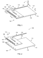
- FIG. 1 shows the lighting module 100 in its assembled form.
- the lighting module 100 has a back side 102 (or "back plane 102") and a front side 104 (or “lighted plane 104") from which the lighting module 100 emits light.
- the lighting module 100 also has a lit edge 106 and one or more an unlit edges (e.g., edges 110, 112, 114).
- the lighting module 100 includes a substrate 116 and a waveguide 118 secured to the substrate 110.
- the waveguide 118 disperses light from the lit edge 106 to the unlit edges to illuminate and emit light from the front side 104.
- the substrate 110 can include a populated portion 120 and an elongated portion 122 extending from the populated portion 120.
- the elongated portion 122 can extend along one of the unlit edges (e.g., edge 110), terminating at or near another of the unlit edges (e.g., edge 112).
- the substrate 102 can comprise a printed circuit board (PCB) and like laminated structures to support and electrically connect components (e.g., electrical components) mounted thereon.
- the lighting module 100 can include a heat sink 124, a processor 126, memory 128, and a power unit 130, which itself can include a plurality of electrical components not shown herein.
- the lighting module 100 also includes an interface (e.g., a first interface 132 and a second interface 134) that permits adjacent ones of the lighting modules 100 to communicate with one another.
- the interface can include a connector (e.g., the first interface 132) and a port (e.g., the second interface 134), or combination thereof, wherein the connector can couple with the port when the lighting module 100 is assembled adjacent other ones of the lighting module 100 in the LED lighting device.
- the lighting module 100 includes a plurality of light emitting diodes (LEDs) 136 and corresponding openings 138 that penetrate the waveguide 118.
- the openings 138 expose the LEDs 136 to the interior of the waveguide 118.
- the present disclosure contemplates the use of various types of LEDs (e.g., surface mount, through-hole mount, organic LEDs, etc.) in various colors (e.g., red, green, blue, orange, etc.) and combinations of colors.
- the LEDs 136 traverses the lit edge 106. Spacing of the LEDs 136 permits uniform distribution of light across the front side 104.
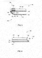
- FIG. 3 illustrates a cross-section of the lit edge 106 taken at line A-A of FIG. 1 .
- the waveguide 118 includes an upper member 140, a lower member 142, and an outer edge member 144 proximate the LEDs 136.
- the outer edge member 144 directs light from the LEDs 136 away from the lit edge 106 towards the interior of the waveguide 118, as generally indicated by the arrow 146.
- the lighting module 112 may include a reflector element 148 and/or optics element 150, both of which may help to disperse light from the lit edge 106 and across the front side 104 of the lighting module 100.
- the waveguide 118 can comprise acrylic or similar polymer or other materials that are amenable to parameters of construction (e.g., cost) of the lighting module 100. Suitable materials are likewise compatible with monolithic construction of the waveguide 118 using various extruding, molding, and mass production techniques.
- the upper member 140 can be substantially reflective or employ a reflective coating that propagates light throughout the interior of the waveguide 118.
- the lower member 142 can be partially and/or fully transparent to light, although construction of the lower member 142 may also take into consideration properties of the emitted light that is proper for lighting the given environment (e.g., office space, home, etc.).
- Layers of material may be added to, or as part of, the lower member 142 to change the emissive properties of the lighting module 100 as necessary.
- Example materials may be more or less reflective, refractive, or have properties that effect the diffusion of light and specific light wavelengths through the lower member 142.
- the outer edge member 144 can comprise a curve or radius (as shown) of known diameter that extends along the length of the lit edge 106.
- the radius can, in combination with material and/or coating selection, provide appropriate reflective properties to direct light from the lit edge 106.
- This disclosure contemplates other shapes and features for the outer edge member 144 including tapers, chamfers, or angular features, which are angled relative to the LEDs 136 to direct light into the interior of the waveguide 118.
- the reflector element 148 can add and/or improve reflective properties along the lit edge 106 of the waveguide 118.
- the reflector element 148 can be a separate member, secured to or incorporated into the waveguide 118, or a material layer (e.g., a coating) with light-reflective properties.
- the optics element 150 can further influence the direction at which light from the LEDs 134 disperses.
- the optics element 150 include reflectors (e.g., cup reflectors) that surround all or a portion of the LEDs 136. Reflectors of this type are often included as part of the LED assembly.
- the optics element 150 may be a lens or lens element that is attached proximate the LED 136. Light from the LEDs 136 can impinge on the lens element, pass through the lens element, and then disperse into the interior of the waveguide 118.
- the optics element 150 may include an optical layer of material that is disposed onto a surface of the LEDs 136. This optical layer can have optical properties that effect changes, e.g., in the direction of light as the light leaves the LEDs 136.
- the heat sink 124 dissipates heat away from the LEDs 136.
- the heat sink 124 can comprise thermally-conductive materials (e.g., metals) that can transfer heat by conduction, convection, and radiation.
- the heat sink 124 is in thermal contact with the LEDs 136, either collectively using an elongated piece of material that spans at least a portion of the lit edge 106, or singularly using a properly sized and situated piece of material thermally contacting the LEDs 136 individually.
- FIG. 4 shows a cross section of the unlit edge 112 taken at line B-B of FIG. 1 .
- the waveguide 118 includes an outer edge member 152, which has a curved or otherwise tapered profile.
- the end of the elongated portion 122 also has a profile that can match and/or continue the profile of the outer edge member 152, but that also provides sufficient area to include the second interface 132 thereon.
- the profile of the outer edge member 152 matches the profile (e.g., radius) of the outer edge member 150 ( FIG. 3 ) on the lit edge 106. Matching these profiles allows these two components to mate together, a feature that is important when constructing the LED lighting device, as discussed in more detail below.
- FIG. 5 illustrates a top view of an example embodiment of an LED lighting device 200, which can replace many conventional lighting fixtures, e.g., fluorescent lighting fixtures.
- the LED lighting device 200 includes a plurality of lighting modules 202 (e.g., the lighting module 100 of FIGS. 1, 2 , 3, and 4 ) and a frame 204 disposed about the periphery of the lighting modules 202.
- the frame 204 can include one or more members 206, which can be separate pieces or can be formed monolithically, e.g., as a pressed, stamped, or extruded parts. Configurations of the frame 204 provide features that can connect and/or support the LED lighting device 200 in position as part of a suspended ceiling.
- the frame 200 support the lighting modules 202 about, for example, one or more edges of the lighting modules 202.
- the frame 204 can comprise metals (e.g., aluminum), plastics, and composites, as well as combinations of materials as desired and compatible with the application or implementation in which the LED lighting device 200 is to deploy.
- the lighting modules 200 form an array 208, which in the present example is a 2 x 2 array but can include any number of the lighting modules 202 as desired.
- the lighting modules 202 can be removed individually from the array 208 and replaced with another one of the light module 202. Abutting the lighting modules 202 causes the connectors to engage. This feature is beneficial to allow maintenance to occur without the need to dismantle and/or remove the entire LED lighting device 200 from its mounted position, e.g., in a ceiling.
- the lighting modules 202 can couple to one or more adjacent modules via a connector or other implement through which signals (e.g., electrical signals) or "inputs and outputs" can travel. In this abutted configuration, the lighting modules 202 can share, among other things, power signals and instructive signals that dictate operation of the lighting modules 202 and/or the LED lighting device 200 in general.
- one of the lighting modules 202 may operate as a master control module, which is configured to execute certain executable instructions and commands that dictate operation of the LED lighting device 200.
- the master control module may be equipped with a specific processor for this purpose or, in one example, the master control module may be designated by way of factory or manufacturing calibration and settings.
- a bottom view (C-C) of the LED lighting device 200 provides an example illustration of the lighted side from which the LED lighting device 200 emits light.
- the lighting modules 202 include a plurality of light emitting diodes (LEDs) 210, extending along one edge of the lighting modules 202.
- LEDs light emitting diodes
- Light generated by the LEDs 210 illuminate the lighted side to form an illuminated surface area 212.
- the illuminated surface area 212 is lighted in its entirety, although selective operation of the lighting modules 202 can vary illumination and thus illuminate only portions of the illuminated surface area 212.
- the LED lighting device 200 can include a diffusion member to hide the mating lines (shown generally by the dashed lines 214 in FIG. 6 ) adjacent lighting modules 202 form.
- the mating lines 214 identify the edges (e.g., the edges 106, 110, 112, 114 of FIG. 1 ) of the individual lighting modules 202.
- the diffusion member can reside as a separate component of the assembly. Examples of the diffusion member can comprise a sheet or thin film of plastic, glass, or other materials with optical properties that effectively hide the mating lines 214 from view but that do not inhibit emission of light from the illuminated surface area 212.
- FIG. 7 illustrates a high-level wiring schematic of an LED lighting device 300 (e.g. the LED lighting device 200 of FIGS. 5 and 6 ).
- the LED lighting device 300 comprises a plurality of lighting modules 302.
- Each of the lighting modules 302 includes a light engine 304 with a plurality of LEDs 306.
- the light engine 304 couples with a power unit 306 and a control circuit 308.
- the control circuit 308 can include a processor 310, memory 312, and a drive circuit 314 with circuitry to operate, e.g., the light engine 304 and the power unit 306.
- the lighting modules 302 also include an interface with a first interface 318 and a second interface 320.
- the processor 310 is a central processing unit (CPU) such as an ASIC and/or an FPGA.
- the processor 310 can also include state machine circuitry or other suitable components capable of receiving inputs from the circuitry 314 and/or directly from the light engine 304, the interface 316, and/or other components (e.g., the power unit 306).
- the memory 312 comprises volatile and non-volatile memory and can be used for storage of software (or firmware) instructions and configuration settings.
- the processor 310, the memory 312, and the circuitry 314 can be contained in a single integrated circuit (IC) or other component.
- the processor 310 can include internal program memory such as RAM and/or ROM. Similarly, any one or more of functions of these components can be distributed across additional components (e.g., multiple processors or other components).
- lighting modules such as those shown in FIGS. 1, 2 , 3, 4 , 5 , 6 , and 7 , permit flexible arrangement and construction of LED lighting devices.
- the lighting modules can engage one another, e.g., via connectors, thereby permitting communication of signals that can facilitate selective operation.
- connection of one lighting module to another permits sharing of power among many lighting modules that often comprise a lighting device. This feature reduces the size and other requirements that often necessitate large and unwieldy power supplies for use with larger LED lighting devices and, in particular, LED lighting devices having edge-lit displays.
Applications Claiming Priority (1)
| Application Number | Priority Date | Filing Date | Title |
|---|---|---|---|
| US13/289,869 US8632236B2 (en) | 2011-11-04 | 2011-11-04 | LED lighting module and lighting device comprised thereof |
Publications (2)
| Publication Number | Publication Date |
|---|---|
| EP2589853A1 true EP2589853A1 (fr) | 2013-05-08 |
| EP2589853B1 EP2589853B1 (fr) | 2015-07-29 |
Family
ID=47627888
Family Applications (1)
| Application Number | Title | Priority Date | Filing Date |
|---|---|---|---|
| EP12191043.4A Not-in-force EP2589853B1 (fr) | 2011-11-04 | 2012-11-02 | Module d'éclairage et dispositif lumineux comportant de tels modules |
Country Status (3)
| Country | Link |
|---|---|
| US (1) | US8632236B2 (fr) |
| EP (1) | EP2589853B1 (fr) |
| CN (1) | CN103090223B (fr) |
Cited By (1)
| Publication number | Priority date | Publication date | Assignee | Title |
|---|---|---|---|---|
| EP3875840A1 (fr) * | 2020-03-03 | 2021-09-08 | Prosperous (Ningbo) Lighting Appliance Co., Ltd. | Lampe d'armoire indépendante et épissurable |
Families Citing this family (4)
| Publication number | Priority date | Publication date | Assignee | Title |
|---|---|---|---|---|
| US9777897B2 (en) * | 2012-02-07 | 2017-10-03 | Cree, Inc. | Multiple panel troffer-style fixture |
| DK2841844T3 (da) * | 2012-04-27 | 2017-11-06 | Schreder | Forbedringer i eller relaterende til multifarvede lyskilder |
| CN103928828A (zh) * | 2014-04-01 | 2014-07-16 | 京东方科技集团股份有限公司 | 背光源以及显示装置 |
| US9541255B2 (en) | 2014-05-28 | 2017-01-10 | Lsi Industries, Inc. | Luminaires and reflector modules |
Citations (8)
| Publication number | Priority date | Publication date | Assignee | Title |
|---|---|---|---|---|
| US20040240230A1 (en) * | 2003-05-30 | 2004-12-02 | Shigemasa Kitajima | Light-emitting unit |
| US20050116667A1 (en) * | 2001-09-17 | 2005-06-02 | Color Kinetics, Incorporated | Tile lighting methods and systems |
| US20070133193A1 (en) * | 2005-12-12 | 2007-06-14 | Led Folio Corporation | Low-clearance lighting |
| US20070218751A1 (en) * | 2004-03-11 | 2007-09-20 | Element Labs, Inc. | Mounting system for light tiles attached to tensioned cables |
| US20080037284A1 (en) * | 2006-04-21 | 2008-02-14 | Rudisill Charles A | Lightguide tile modules and modular lighting system |
| WO2008157723A1 (fr) * | 2007-06-21 | 2008-12-24 | Nila Inc. | Ensembles d'éclairage modulaires |
| WO2010140103A1 (fr) * | 2009-06-02 | 2010-12-09 | Koninklijke Philips Electronics N.V. | Appareil et système pour séparer un espace |
| US20110255303A1 (en) * | 2010-04-16 | 2011-10-20 | Anthony John Nichol | Illumination device comprising a film-based lightguide |
Family Cites Families (28)
| Publication number | Priority date | Publication date | Assignee | Title |
|---|---|---|---|---|
| US5613751A (en) | 1995-06-27 | 1997-03-25 | Lumitex, Inc. | Light emitting panel assemblies |
| US6481131B2 (en) | 2000-10-03 | 2002-11-19 | Amanda Gianotti | LED illuminated plaque |
| US7063449B2 (en) | 2002-11-21 | 2006-06-20 | Element Labs, Inc. | Light emitting diode (LED) picture element |
| DE10314525A1 (de) * | 2003-03-31 | 2004-11-04 | Osram Opto Semiconductors Gmbh | Verfahren zur Herstellung einer Beleuchtungsvorrichtung und Beleuchtungsvorrichtung |
| EP1653149B1 (fr) * | 2003-06-16 | 2011-10-19 | Mitsubishi Denki Kabushiki Kaisha | Dispositif de source de lumiere plane et dispositif d'affichage comprenant celui-ci |
| US7172324B2 (en) | 2004-01-05 | 2007-02-06 | Leotek Electronics Corporation | Internally illuminated light panel with LED modules having light redirecting devices |
| KR20050107033A (ko) * | 2004-05-07 | 2005-11-11 | 삼성전자주식회사 | 발광 다이오드 모듈 및 이를 구비한 액정표시장치 |
| KR20060030350A (ko) * | 2004-10-05 | 2006-04-10 | 삼성전자주식회사 | 백색광 발생 유닛, 이를 갖는 백라이트 어셈블리 및 이를갖는 액정표시장치 |
| US7311431B2 (en) * | 2005-04-01 | 2007-12-25 | Avago Technologies Ecbu Ip Pte Ltd | Light-emitting apparatus having a plurality of adjacent, overlapping light-guide plates |
| US7909496B2 (en) | 2006-02-01 | 2011-03-22 | Koninklijke Philips Electronics N.V. | Lighting system for creating an illuminated surface |
| CN100468170C (zh) * | 2006-02-10 | 2009-03-11 | 鸿富锦精密工业(深圳)有限公司 | 背光系统 |
| US7736044B2 (en) * | 2006-05-26 | 2010-06-15 | Avago Technologies General Ip (Singapore) Pte. Ltd. | Indirect lighting device for light guide illumination |
| US7959341B2 (en) | 2006-07-20 | 2011-06-14 | Rambus International Ltd. | LED color management and display systems |
| JP5142495B2 (ja) * | 2006-08-07 | 2013-02-13 | 株式会社ジャパンディスプレイイースト | 液晶表示装置 |
| TWI335468B (en) * | 2006-09-29 | 2011-01-01 | Chimei Innolux Corp | Liquid crystal display device |
| CN101622494A (zh) * | 2007-04-26 | 2010-01-06 | 夏普株式会社 | 发光元件和液晶显示装置 |
| US7796209B2 (en) * | 2007-07-27 | 2010-09-14 | Sharp Kabushiki Kaisha | Illumination device and liquid crystal display device |
| US8550684B2 (en) * | 2007-12-19 | 2013-10-08 | Oree, Inc. | Waveguide-based packaging structures and methods for discrete lighting elements |
| EP2288957B1 (fr) * | 2008-05-27 | 2018-04-18 | LG Electronics Inc. | Unité de rétroéclairage à del et dispositif d affichage à cristaux liquides utilisant l unité |
| TWI397195B (zh) | 2008-07-07 | 2013-05-21 | Advanced Optoelectronic Tech | 發光二極體元件及背光模組 |
| US20100027293A1 (en) | 2008-07-30 | 2010-02-04 | Intematix Corporation | Light Emitting Panel |
| KR101558166B1 (ko) * | 2008-12-11 | 2015-10-12 | 삼성디스플레이 주식회사 | 광출사 모듈 및 이를 갖는 표시장치 |
| US20100177749A1 (en) | 2009-01-13 | 2010-07-15 | Metrologic Instruments, Inc. | Methods of and apparatus for programming and managing diverse network components, including electronic-ink based display devices, in a mesh-type wireless communication network |
| US20100195350A1 (en) | 2009-02-03 | 2010-08-05 | Richard Schattinger | Modular LED light device |
| TWM373503U (en) * | 2009-03-06 | 2010-02-01 | Chunghwa Picture Tubes Ltd | Backlight module |
| TW201105893A (en) | 2009-08-05 | 2011-02-16 | Leotek Electronics Corp | LED lamp module and LED lamp |
| TWI416221B (zh) | 2009-12-30 | 2013-11-21 | Au Optronics Corp | 具局部光源控制功能之背光模組 |
| US20110205757A1 (en) * | 2010-02-22 | 2011-08-25 | Whyte Robert H | Thin light emitting modular panel system |
-
2011
- 2011-11-04 US US13/289,869 patent/US8632236B2/en not_active Expired - Fee Related
-
2012
- 2012-11-02 CN CN201210431805.2A patent/CN103090223B/zh not_active Expired - Fee Related
- 2012-11-02 EP EP12191043.4A patent/EP2589853B1/fr not_active Not-in-force
Patent Citations (8)
| Publication number | Priority date | Publication date | Assignee | Title |
|---|---|---|---|---|
| US20050116667A1 (en) * | 2001-09-17 | 2005-06-02 | Color Kinetics, Incorporated | Tile lighting methods and systems |
| US20040240230A1 (en) * | 2003-05-30 | 2004-12-02 | Shigemasa Kitajima | Light-emitting unit |
| US20070218751A1 (en) * | 2004-03-11 | 2007-09-20 | Element Labs, Inc. | Mounting system for light tiles attached to tensioned cables |
| US20070133193A1 (en) * | 2005-12-12 | 2007-06-14 | Led Folio Corporation | Low-clearance lighting |
| US20080037284A1 (en) * | 2006-04-21 | 2008-02-14 | Rudisill Charles A | Lightguide tile modules and modular lighting system |
| WO2008157723A1 (fr) * | 2007-06-21 | 2008-12-24 | Nila Inc. | Ensembles d'éclairage modulaires |
| WO2010140103A1 (fr) * | 2009-06-02 | 2010-12-09 | Koninklijke Philips Electronics N.V. | Appareil et système pour séparer un espace |
| US20110255303A1 (en) * | 2010-04-16 | 2011-10-20 | Anthony John Nichol | Illumination device comprising a film-based lightguide |
Cited By (1)
| Publication number | Priority date | Publication date | Assignee | Title |
|---|---|---|---|---|
| EP3875840A1 (fr) * | 2020-03-03 | 2021-09-08 | Prosperous (Ningbo) Lighting Appliance Co., Ltd. | Lampe d'armoire indépendante et épissurable |
Also Published As
| Publication number | Publication date |
|---|---|
| US8632236B2 (en) | 2014-01-21 |
| CN103090223B (zh) | 2017-07-11 |
| CN103090223A (zh) | 2013-05-08 |
| US20130114295A1 (en) | 2013-05-09 |
| EP2589853B1 (fr) | 2015-07-29 |
Similar Documents
| Publication | Publication Date | Title |
|---|---|---|
| EP2553316B1 (fr) | Tube de lampe à del avec répartition lumineuse latérale double | |
| US20110205757A1 (en) | Thin light emitting modular panel system | |
| EP2589853B1 (fr) | Module d'éclairage et dispositif lumineux comportant de tels modules | |
| CA2826903C (fr) | Luminaire creant une lame lumineuse | |
| US9605830B1 (en) | Systems, methods and devices for an LED lighting module with a light transmissive cover | |
| MX2011005387A (es) | Accesorio de iluminacion de led. | |
| EP2076802B1 (fr) | Panneaux électroluminescents pour des dispositifs d'affichage | |
| AU2016244591A1 (en) | Light-emitting diode type lighting device | |
| CN103672634B (zh) | 模块式平板灯 | |
| JP2013045604A (ja) | 照明器具 | |
| US20110285268A1 (en) | Light-emitting device | |
| US9951927B2 (en) | Lighting device and luminaire | |
| JP3211553U (ja) | 照明装置 | |
| US20130135853A1 (en) | Light-guiding element, light-emitting diode lamp tube and illumination lamp | |
| KR101601801B1 (ko) | 아크형 광확산 구조의 led 조명등 | |
| JP3205851U (ja) | 照明灯具 | |
| WO2019154930A1 (fr) | Module de source lumineuse planaire à diodes électroluminescentes | |
| CN203309718U (zh) | 模块式平板灯 | |
| CN213983037U (zh) | 一种led面板灯 | |
| JP2009104197A (ja) | 内照式掲示器の光源構造 | |
| US20150168639A1 (en) | Light-emitting device for generating a specific light pattern and light-guiding unit thereof | |
| JP2010070962A (ja) | 照明手摺り | |
| KR101790050B1 (ko) | 발광소자 어레이 | |
| EP3244124A1 (fr) | Luminaire et dispositif de revêtement de surface | |
| GB2520344A (en) | LED luminaire |
Legal Events
| Date | Code | Title | Description |
|---|---|---|---|
| PUAI | Public reference made under article 153(3) epc to a published international application that has entered the european phase |
Free format text: ORIGINAL CODE: 0009012 |
|
| AK | Designated contracting states |
Kind code of ref document: A1 Designated state(s): AL AT BE BG CH CY CZ DE DK EE ES FI FR GB GR HR HU IE IS IT LI LT LU LV MC MK MT NL NO PL PT RO RS SE SI SK SM TR |
|
| AX | Request for extension of the european patent |
Extension state: BA ME |
|
| 17P | Request for examination filed |
Effective date: 20131108 |
|
| RBV | Designated contracting states (corrected) |
Designated state(s): AL AT BE BG CH CY CZ DE DK EE ES FI FR GB GR HR HU IE IS IT LI LT LU LV MC MK MT NL NO PL PT RO RS SE SI SK SM TR |
|
| 17Q | First examination report despatched |
Effective date: 20140108 |
|
| GRAP | Despatch of communication of intention to grant a patent |
Free format text: ORIGINAL CODE: EPIDOSNIGR1 |
|
| RIC1 | Information provided on ipc code assigned before grant |
Ipc: G02B 6/00 20060101ALI20150211BHEP Ipc: F21V 33/00 20060101ALN20150211BHEP Ipc: F21S 2/00 20060101AFI20150211BHEP Ipc: F21V 23/06 20060101ALN20150211BHEP Ipc: F21V 21/005 20060101ALN20150211BHEP Ipc: F21V 23/02 20060101ALI20150211BHEP Ipc: F21V 3/02 20060101ALN20150211BHEP Ipc: F21Y 101/02 20060101ALN20150211BHEP |
|
| INTG | Intention to grant announced |
Effective date: 20150303 |
|
| GRAS | Grant fee paid |
Free format text: ORIGINAL CODE: EPIDOSNIGR3 |
|
| GRAA | (expected) grant |
Free format text: ORIGINAL CODE: 0009210 |
|
| AK | Designated contracting states |
Kind code of ref document: B1 Designated state(s): AL AT BE BG CH CY CZ DE DK EE ES FI FR GB GR HR HU IE IS IT LI LT LU LV MC MK MT NL NO PL PT RO RS SE SI SK SM TR |
|
| REG | Reference to a national code |
Ref country code: GB Ref legal event code: FG4D |
|
| REG | Reference to a national code |
Ref country code: CH Ref legal event code: EP |
|
| REG | Reference to a national code |
Ref country code: AT Ref legal event code: REF Ref document number: 739611 Country of ref document: AT Kind code of ref document: T Effective date: 20150815 |
|
| REG | Reference to a national code |
Ref country code: IE Ref legal event code: FG4D |
|
| REG | Reference to a national code |
Ref country code: DE Ref legal event code: R096 Ref document number: 602012009090 Country of ref document: DE |
|
| REG | Reference to a national code |
Ref country code: NL Ref legal event code: FP |
|
| REG | Reference to a national code |
Ref country code: FR Ref legal event code: PLFP Year of fee payment: 4 |
|
| REG | Reference to a national code |
Ref country code: AT Ref legal event code: MK05 Ref document number: 739611 Country of ref document: AT Kind code of ref document: T Effective date: 20150729 |
|
| REG | Reference to a national code |
Ref country code: LT Ref legal event code: MG4D |
|
| PG25 | Lapsed in a contracting state [announced via postgrant information from national office to epo] |
Ref country code: NO Free format text: LAPSE BECAUSE OF FAILURE TO SUBMIT A TRANSLATION OF THE DESCRIPTION OR TO PAY THE FEE WITHIN THE PRESCRIBED TIME-LIMIT Effective date: 20151029 Ref country code: FI Free format text: LAPSE BECAUSE OF FAILURE TO SUBMIT A TRANSLATION OF THE DESCRIPTION OR TO PAY THE FEE WITHIN THE PRESCRIBED TIME-LIMIT Effective date: 20150729 Ref country code: LV Free format text: LAPSE BECAUSE OF FAILURE TO SUBMIT A TRANSLATION OF THE DESCRIPTION OR TO PAY THE FEE WITHIN THE PRESCRIBED TIME-LIMIT Effective date: 20150729 Ref country code: GR Free format text: LAPSE BECAUSE OF FAILURE TO SUBMIT A TRANSLATION OF THE DESCRIPTION OR TO PAY THE FEE WITHIN THE PRESCRIBED TIME-LIMIT Effective date: 20151030 Ref country code: LT Free format text: LAPSE BECAUSE OF FAILURE TO SUBMIT A TRANSLATION OF THE DESCRIPTION OR TO PAY THE FEE WITHIN THE PRESCRIBED TIME-LIMIT Effective date: 20150729 |
|
| PG25 | Lapsed in a contracting state [announced via postgrant information from national office to epo] |
Ref country code: AT Free format text: LAPSE BECAUSE OF FAILURE TO SUBMIT A TRANSLATION OF THE DESCRIPTION OR TO PAY THE FEE WITHIN THE PRESCRIBED TIME-LIMIT Effective date: 20150729 Ref country code: PT Free format text: LAPSE BECAUSE OF FAILURE TO SUBMIT A TRANSLATION OF THE DESCRIPTION OR TO PAY THE FEE WITHIN THE PRESCRIBED TIME-LIMIT Effective date: 20151130 Ref country code: IS Free format text: LAPSE BECAUSE OF FAILURE TO SUBMIT A TRANSLATION OF THE DESCRIPTION OR TO PAY THE FEE WITHIN THE PRESCRIBED TIME-LIMIT Effective date: 20151129 Ref country code: RS Free format text: LAPSE BECAUSE OF FAILURE TO SUBMIT A TRANSLATION OF THE DESCRIPTION OR TO PAY THE FEE WITHIN THE PRESCRIBED TIME-LIMIT Effective date: 20150729 Ref country code: ES Free format text: LAPSE BECAUSE OF FAILURE TO SUBMIT A TRANSLATION OF THE DESCRIPTION OR TO PAY THE FEE WITHIN THE PRESCRIBED TIME-LIMIT Effective date: 20150729 Ref country code: SE Free format text: LAPSE BECAUSE OF FAILURE TO SUBMIT A TRANSLATION OF THE DESCRIPTION OR TO PAY THE FEE WITHIN THE PRESCRIBED TIME-LIMIT Effective date: 20150729 Ref country code: HR Free format text: LAPSE BECAUSE OF FAILURE TO SUBMIT A TRANSLATION OF THE DESCRIPTION OR TO PAY THE FEE WITHIN THE PRESCRIBED TIME-LIMIT Effective date: 20150729 Ref country code: PL Free format text: LAPSE BECAUSE OF FAILURE TO SUBMIT A TRANSLATION OF THE DESCRIPTION OR TO PAY THE FEE WITHIN THE PRESCRIBED TIME-LIMIT Effective date: 20150729 |
|
| PG25 | Lapsed in a contracting state [announced via postgrant information from national office to epo] |
Ref country code: DK Free format text: LAPSE BECAUSE OF FAILURE TO SUBMIT A TRANSLATION OF THE DESCRIPTION OR TO PAY THE FEE WITHIN THE PRESCRIBED TIME-LIMIT Effective date: 20150729 Ref country code: EE Free format text: LAPSE BECAUSE OF FAILURE TO SUBMIT A TRANSLATION OF THE DESCRIPTION OR TO PAY THE FEE WITHIN THE PRESCRIBED TIME-LIMIT Effective date: 20150729 Ref country code: CZ Free format text: LAPSE BECAUSE OF FAILURE TO SUBMIT A TRANSLATION OF THE DESCRIPTION OR TO PAY THE FEE WITHIN THE PRESCRIBED TIME-LIMIT Effective date: 20150729 Ref country code: IT Free format text: LAPSE BECAUSE OF FAILURE TO SUBMIT A TRANSLATION OF THE DESCRIPTION OR TO PAY THE FEE WITHIN THE PRESCRIBED TIME-LIMIT Effective date: 20150729 Ref country code: SK Free format text: LAPSE BECAUSE OF FAILURE TO SUBMIT A TRANSLATION OF THE DESCRIPTION OR TO PAY THE FEE WITHIN THE PRESCRIBED TIME-LIMIT Effective date: 20150729 |
|
| REG | Reference to a national code |
Ref country code: DE Ref legal event code: R097 Ref document number: 602012009090 Country of ref document: DE |
|
| PG25 | Lapsed in a contracting state [announced via postgrant information from national office to epo] |
Ref country code: RO Free format text: LAPSE BECAUSE OF FAILURE TO SUBMIT A TRANSLATION OF THE DESCRIPTION OR TO PAY THE FEE WITHIN THE PRESCRIBED TIME-LIMIT Effective date: 20150729 |
|
| PLBE | No opposition filed within time limit |
Free format text: ORIGINAL CODE: 0009261 |
|
| STAA | Information on the status of an ep patent application or granted ep patent |
Free format text: STATUS: NO OPPOSITION FILED WITHIN TIME LIMIT |
|
| PG25 | Lapsed in a contracting state [announced via postgrant information from national office to epo] |
Ref country code: LU Free format text: LAPSE BECAUSE OF FAILURE TO SUBMIT A TRANSLATION OF THE DESCRIPTION OR TO PAY THE FEE WITHIN THE PRESCRIBED TIME-LIMIT Effective date: 20151102 Ref country code: MC Free format text: LAPSE BECAUSE OF FAILURE TO SUBMIT A TRANSLATION OF THE DESCRIPTION OR TO PAY THE FEE WITHIN THE PRESCRIBED TIME-LIMIT Effective date: 20150729 |
|
| REG | Reference to a national code |
Ref country code: CH Ref legal event code: PL |
|
| 26N | No opposition filed |
Effective date: 20160502 |
|
| PG25 | Lapsed in a contracting state [announced via postgrant information from national office to epo] |
Ref country code: CH Free format text: LAPSE BECAUSE OF NON-PAYMENT OF DUE FEES Effective date: 20151130 Ref country code: LI Free format text: LAPSE BECAUSE OF NON-PAYMENT OF DUE FEES Effective date: 20151130 |
|
| REG | Reference to a national code |
Ref country code: IE Ref legal event code: MM4A |
|
| PG25 | Lapsed in a contracting state [announced via postgrant information from national office to epo] |
Ref country code: SI Free format text: LAPSE BECAUSE OF FAILURE TO SUBMIT A TRANSLATION OF THE DESCRIPTION OR TO PAY THE FEE WITHIN THE PRESCRIBED TIME-LIMIT Effective date: 20150729 |
|
| PG25 | Lapsed in a contracting state [announced via postgrant information from national office to epo] |
Ref country code: IE Free format text: LAPSE BECAUSE OF NON-PAYMENT OF DUE FEES Effective date: 20151102 |
|
| REG | Reference to a national code |
Ref country code: FR Ref legal event code: PLFP Year of fee payment: 5 |
|
| PG25 | Lapsed in a contracting state [announced via postgrant information from national office to epo] |
Ref country code: BE Free format text: LAPSE BECAUSE OF FAILURE TO SUBMIT A TRANSLATION OF THE DESCRIPTION OR TO PAY THE FEE WITHIN THE PRESCRIBED TIME-LIMIT Effective date: 20150729 |
|
| PG25 | Lapsed in a contracting state [announced via postgrant information from national office to epo] |
Ref country code: SM Free format text: LAPSE BECAUSE OF FAILURE TO SUBMIT A TRANSLATION OF THE DESCRIPTION OR TO PAY THE FEE WITHIN THE PRESCRIBED TIME-LIMIT Effective date: 20150729 Ref country code: BG Free format text: LAPSE BECAUSE OF FAILURE TO SUBMIT A TRANSLATION OF THE DESCRIPTION OR TO PAY THE FEE WITHIN THE PRESCRIBED TIME-LIMIT Effective date: 20150729 Ref country code: HU Free format text: LAPSE BECAUSE OF FAILURE TO SUBMIT A TRANSLATION OF THE DESCRIPTION OR TO PAY THE FEE WITHIN THE PRESCRIBED TIME-LIMIT; INVALID AB INITIO Effective date: 20121102 |
|
| PG25 | Lapsed in a contracting state [announced via postgrant information from national office to epo] |
Ref country code: CY Free format text: LAPSE BECAUSE OF FAILURE TO SUBMIT A TRANSLATION OF THE DESCRIPTION OR TO PAY THE FEE WITHIN THE PRESCRIBED TIME-LIMIT Effective date: 20150729 |
|
| PG25 | Lapsed in a contracting state [announced via postgrant information from national office to epo] |
Ref country code: MT Free format text: LAPSE BECAUSE OF FAILURE TO SUBMIT A TRANSLATION OF THE DESCRIPTION OR TO PAY THE FEE WITHIN THE PRESCRIBED TIME-LIMIT Effective date: 20150729 |
|
| REG | Reference to a national code |
Ref country code: FR Ref legal event code: PLFP Year of fee payment: 6 |
|
| PG25 | Lapsed in a contracting state [announced via postgrant information from national office to epo] |
Ref country code: TR Free format text: LAPSE BECAUSE OF FAILURE TO SUBMIT A TRANSLATION OF THE DESCRIPTION OR TO PAY THE FEE WITHIN THE PRESCRIBED TIME-LIMIT Effective date: 20150729 Ref country code: MK Free format text: LAPSE BECAUSE OF FAILURE TO SUBMIT A TRANSLATION OF THE DESCRIPTION OR TO PAY THE FEE WITHIN THE PRESCRIBED TIME-LIMIT Effective date: 20150729 |
|
| REG | Reference to a national code |
Ref country code: FR Ref legal event code: PLFP Year of fee payment: 7 |
|
| PG25 | Lapsed in a contracting state [announced via postgrant information from national office to epo] |
Ref country code: AL Free format text: LAPSE BECAUSE OF FAILURE TO SUBMIT A TRANSLATION OF THE DESCRIPTION OR TO PAY THE FEE WITHIN THE PRESCRIBED TIME-LIMIT Effective date: 20150729 |
|
| RIC2 | Information provided on ipc code assigned after grant |
Ipc: G02B 6/00 20060101ALI20150211BHEP Ipc: F21V 21/005 20060101ALN20150211BHEP Ipc: F21V 3/02 20060101ALN20150211BHEP Ipc: F21S 2/00 20160101AFI20150211BHEP Ipc: F21Y 101/02 20000101ALN20150211BHEP Ipc: F21V 23/06 20060101ALN20150211BHEP Ipc: F21V 33/00 20060101ALN20150211BHEP Ipc: F21V 23/02 20060101ALI20150211BHEP |
|
| REG | Reference to a national code |
Ref country code: NL Ref legal event code: HC Owner name: CURRENT LIGHTING SOLUTIONS, LLC; US Free format text: DETAILS ASSIGNMENT: CHANGE OF OWNER(S), CHANGE OF OWNER(S) NAME; FORMER OWNER NAME: GE LIGHTING SOLUTIONS, LLC Effective date: 20200911 |
|
| PGFP | Annual fee paid to national office [announced via postgrant information from national office to epo] |
Ref country code: NL Payment date: 20201029 Year of fee payment: 9 |
|
| PGFP | Annual fee paid to national office [announced via postgrant information from national office to epo] |
Ref country code: DE Payment date: 20201020 Year of fee payment: 9 Ref country code: GB Payment date: 20201021 Year of fee payment: 9 Ref country code: FR Payment date: 20201021 Year of fee payment: 9 |
|
| REG | Reference to a national code |
Ref country code: DE Ref legal event code: R119 Ref document number: 602012009090 Country of ref document: DE |
|
| REG | Reference to a national code |
Ref country code: NL Ref legal event code: MM Effective date: 20211201 |
|
| GBPC | Gb: european patent ceased through non-payment of renewal fee |
Effective date: 20211102 |
|
| PG25 | Lapsed in a contracting state [announced via postgrant information from national office to epo] |
Ref country code: NL Free format text: LAPSE BECAUSE OF NON-PAYMENT OF DUE FEES Effective date: 20211201 |
|
| PG25 | Lapsed in a contracting state [announced via postgrant information from national office to epo] |
Ref country code: GB Free format text: LAPSE BECAUSE OF NON-PAYMENT OF DUE FEES Effective date: 20211102 Ref country code: DE Free format text: LAPSE BECAUSE OF NON-PAYMENT OF DUE FEES Effective date: 20220601 |
|
| PG25 | Lapsed in a contracting state [announced via postgrant information from national office to epo] |
Ref country code: FR Free format text: LAPSE BECAUSE OF NON-PAYMENT OF DUE FEES Effective date: 20211130 |