EP2589553B1 - Vorrichtung zur Stapelung und Verladung von Blechformteilen an Pressen und Pressenstraßen - Google Patents
Vorrichtung zur Stapelung und Verladung von Blechformteilen an Pressen und Pressenstraßen Download PDFInfo
- Publication number
- EP2589553B1 EP2589553B1 EP20120007392 EP12007392A EP2589553B1 EP 2589553 B1 EP2589553 B1 EP 2589553B1 EP 20120007392 EP20120007392 EP 20120007392 EP 12007392 A EP12007392 A EP 12007392A EP 2589553 B1 EP2589553 B1 EP 2589553B1
- Authority
- EP
- European Patent Office
- Prior art keywords
- sheet metal
- stacking
- sheet
- bed
- press
- Prior art date
- Legal status (The legal status is an assumption and is not a legal conclusion. Google has not performed a legal analysis and makes no representation as to the accuracy of the status listed.)
- Not-in-force
Links
Images


Classifications
-
- B—PERFORMING OPERATIONS; TRANSPORTING
- B65—CONVEYING; PACKING; STORING; HANDLING THIN OR FILAMENTARY MATERIAL
- B65G—TRANSPORT OR STORAGE DEVICES, e.g. CONVEYORS FOR LOADING OR TIPPING, SHOP CONVEYOR SYSTEMS OR PNEUMATIC TUBE CONVEYORS
- B65G61/00—Use of pick-up or transfer devices or of manipulators for stacking or de-stacking articles not otherwise provided for
-
- B—PERFORMING OPERATIONS; TRANSPORTING
- B65—CONVEYING; PACKING; STORING; HANDLING THIN OR FILAMENTARY MATERIAL
- B65G—TRANSPORT OR STORAGE DEVICES, e.g. CONVEYORS FOR LOADING OR TIPPING, SHOP CONVEYOR SYSTEMS OR PNEUMATIC TUBE CONVEYORS
- B65G57/00—Stacking of articles
- B65G57/02—Stacking of articles by adding to the top of the stack
- B65G57/03—Stacking of articles by adding to the top of the stack from above
- B65G57/035—Stacking of articles by adding to the top of the stack from above with a stepwise downward movement of the stack
-
- B—PERFORMING OPERATIONS; TRANSPORTING
- B65—CONVEYING; PACKING; STORING; HANDLING THIN OR FILAMENTARY MATERIAL
- B65G—TRANSPORT OR STORAGE DEVICES, e.g. CONVEYORS FOR LOADING OR TIPPING, SHOP CONVEYOR SYSTEMS OR PNEUMATIC TUBE CONVEYORS
- B65G65/00—Loading or unloading
Definitions
- the invention relates to a device for stacking shaped sheet metal parts in the removal area or outlet area of a press or press line and for loading the formed sheet metal shaped part stack into a prefabricated container or the like.
- the invention further relates to a stacking of sheet metal parts serving table device for use in such a device.
- Presses and press lines usually have a removal area in which the produced sheet metal parts can be picked up and stored in a ready-made precast container or the like.
- automated devices are known from the prior art, such as. B. in the DE 35 02 359 C2 and DE 37 37 913 C2 described.
- a disadvantage of these automated devices is their low flexibility with regard to frequent production changes and the not possible on-site quality control of the sheet metal parts.
- the recording or removal and removal of the sheet metal parts on presses and press lines therefore, especially for large sheet metal parts, usually manually by one or more workers. However, this can lead to unfavorable physical strain for the worker or workers.
- the document DE 38 44 564 A1 discloses a device for stacking sheet metal parts according to the preamble of claim 1.
- the invention provides that the sheet metal parts produced on the press or in the press line are not picked up individually, but are first stacked on a table device in the outlet region of the press or press line to form a stack of sheet metal moldings.
- the sheet metal parts are formed such that they can align themselves when stacked on their own.
- the table device comprises at least two stacking stations, wherein either on one or on the other stacking place coming from the press or the press line sheet metal parts, directly, are stacked on each other. While a complete sheet metal molding stack can be removed from one of the stacking locations or removed by lifting, further shaped sheet metal parts can be stacked on the other stacking station unhindered. According to the invention, these are stacking sites next to one another. In order to avoid lifting of the sheet metal parts during stacking, each stack space is formed with a lowerable in the stack clock table top or the like, the cyclically lowering takes place automatically. In particular, the lowering of the table tops down into the disguised table device is done, creating an optimal work safety for the worker.
- the cyclic lowering of a table top takes place in particular such that the increasing stack height is compensated by the stacking table lowering table top, so that the worker can always take over and pile up the sheet metal parts to be stacked in the same horizontal position.
- the worker (s) monitor the quality and correctness of the stacking process Stacking of the sheet metal parts and can optionally intervene z. B. weed out a defective sheet metal part or to correct the stacking position.
- a sheet-metal shaped article stack may comprise at least 10 shaped sheet metal parts, preferably at least 15 sheet metal shaped parts, particularly preferably at least 20 sheet metal shaped parts and in particular at least 25 sheet metal shaped parts. If the formed sheet metal shaped part stack has reached a predetermined stack height or number of sheet metal shaped parts, the stacking of further sheet metal shaped parts can be continued on another stacking position of the table device. In parallel with this, the complete stack of sheet metal parts can be picked up with a crane-mounted gripper device, transported to a precast container or the like, and deposited therein. After removing a sheet metal molding stack, the lowered table top can be returned to an upper starting position, which can be done automatically or automatically in particular.
- the gripper device comprises at least one hole gripper. It is preferably provided that the gripper device comprises only hole gripper (ie at least one hole gripper). Such a hole gripper has z. B. via a rod-shaped gripping arm, which can be inserted into a channel formed by superimposed recesses in the stacked sheet metal parts. After actuation of at least one spreading member, lifting mandrel or the like, the complete or entire sheet metal molding stack can be lifted and transported (carried by the gripper device) to a precast container and stored therein in a defined position (for example next to one another or else one above the other).
- Such hole gripper are known from the prior art, including z. B. on the DE 198 16 049 B4 is pointed out.
- the use for the lifting and loading of sheet metal molding stacks in the prior art is not provided.
- Such a hole gripper offers the advantage that through the inevitably induced form-fit reliably all sheet metal parts of a sheet metal molding stack can be used and that when loading or moving the sheet metal molding stack individual sheet metal parts can not fall out. Thus, even large stack heights (ie sheet metal part stack with many sheet metal parts) can be handled safely.
- the use of such a hole gripper requires that the formed on the press or in the press line sheet metal parts are formed with suitable recesses.
- the crane-mounted gripper device is manually controlled by a worker.
- the device according to the invention can have at least one slide device with which the sheet-metal shaped parts coming from the press or press line are transferred to the table device.
- the supply to the slide device can, for. B. with a conveyor belt (or outlet conveyor) or the like.
- the end of the chute is preferably always at the same height.
- the increasing stack height is compensated by the stacking table lowering table top.
- the slide device may be adjustable in the height direction and / or in the lateral direction.
- the gripper device is mechanically or pneumatically actuated.
- a load fuse is provided if the pneumatics should fail.
- the table device of the device according to the invention is mounted on floor rails movable.
- the stacking stations are alternately positioned to receive the sheet metal parts and are in particular positioned relative to the slide device.
- the table device is mounted movably on the whole.
- a lock for the table device is provided in order to fix the movable table device in at least one position relative to the rails can.
- the horizontal method or the horizontal movement of the table device on the rails can be accomplished by manual displacement.
- This can be done, for example, with a manually operated lever mechanism, this lever mechanism is designed in particular with a mechanical translation in order to keep the burden of the worker low.
- the table device has a pneumatic or electric drive for moving the table device.
- this pneumatic drive is manually switched on or triggered by a worker and can then z. B. be automatically switched off again by a limit switch when the table device has reached a certain position.
- the table device at least one pneumatically driven adjusting mechanism for the cyclic lowering the table tops. It is preferably provided that the cyclic lowering of a table top is done automatically, what the table device may have at least one light barrier, which is interrupted when stacking a sheet metal part of this sheet metal part, whereby z. B. via a pneumatic valve a defined downward movement or a defined downward stroke of the relevant tabletop is triggered or can be triggered.
- an electrically driven adjusting mechanism for the cyclic lowering of the table tops can be provided.
- the cyclic lowering of the table tops is also done here automatically, including the table device in particular an electronic control, such as. A PLC, in which z. B. the Absenkweg per stacked sheet metal part is stored as a parameter and can be accessed accordingly.
- the table device may have at least one light barrier, which is interrupted when stacking a sheet metal part of this sheet metal part, which, for example.
- a defined downward movement or a defined downward stroke of the relevant table top is triggered or can be triggered .
- an automatic determination of the required downstroke is provided, which can be caused, for example, by a light barrier (stop the downward movement upon release of the light barrier) and in particular by a second light barrier.
- the table device has at least one slip clutch with which the force and / or the speed can be limited when moving up a lowered table tops in the upper starting position.
- a slip clutch is particularly advantageous when an electrically driven adjusting mechanism is provided with which both the cyclic downward movement is accomplished as the upward movement.
- the defined downward stroke is variable and in particular adjustable.
- This can be accomplished, for example, with an adjustable counter unit, wherein each counting step corresponds to a specific travel path or lowering path, or with an electronic control in which a specific parameter is stored as a lowering path per sheet metal part.
- the adjustment can be made based on the measured gap between two adjacent in the sheet metal part stack of sheet metal moldings or based on the possible total number of sheet metal parts in a sheet metal molding stack.
- the upward movement of the relevant table top can be triggered manually or automatically or automatically, and this should only be possible for safety reasons, especially when the sheet metal molding stack was previously removed from the table top.
- the table tops of the table device can have at least one exchangeable and / or adaptable receptacle for the sheet metal shaped parts to be stacked, with which the lowermost sheet metal shaped part to be stacked can be brought into a defined position.
- this receptacle can be exchanged or adapted accordingly.
- a sheet metal part fixed on the table top can also serve as a stacking template.
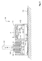
- Fig. 1 shows the removal area of a press or press line 10 for the production of sheet metal parts P.
- the produced sheet metal parts P are cyclically output from the press or press line 10 and conveyed via a conveyor belt 20 in the removal area.
- the removal area there is a device with which the produced and cyclically output sheet metal parts P are implemented, what they are initially stacked and then loaded as a sheet metal molding stack in the prepared precast container 150.
- the device 100 according to the invention is surrounded by a dot-dash line.
- the device 100 includes a mounted on bottom rails 111 and horizontally movable table device 110 with multiple stacking stations A and B on which coming from the press or press line 10 sheet metal parts P to a sheet metal molding stack (see Fig. 2 ) can be stacked on top of each other.
- the stacking stations A and B are formed with table plates 112A and 112B which can be lowered in the stacking cycle.
- the device 100 further includes a slide device 140 via which the sheet metal shaped parts P may gravitationally slip from the conveyor belt 20 to the stacking station A (as shown) or B of the table device 110.
- the device 100 also includes a gripper device 120, with which a complete sheet metal molding stack can be picked up by the table device 110 and set down or set down in one of the finished part containers 150.
- 131 is a crane (For example, a ceiling crane, floor crane or the like) referred to, to which the gripper device 120 is attached (crane-mounted gripper device).
- Denoted at 132 is a rail or gantry for the crane 131.
- the produced sheet-metal shaped parts P coming from the conveyor belt 20 slide over the slide device 140 to one of the stacking stations A or B of the table device 110.
- the affected table top 112A or 112B makes a defined downward stroke, so that the subsequent sheet metal shaped part P can be stacked without lifting on the sheet metal molding stack.
- a resident in the removal area workers or even multiple workers checks the quality of the produced sheet metal parts P before stacking and ensures by manual intervention that the sheet metal parts P are also correctly stacked on the sheet metal molding stack, without this being questionable physical stress for the worker comes.
- the table device 110 is moved on the rails 111, so that an empty stack space A or B is positioned on the chute device 140 for stacking subsequent sheet metal shaped parts P. Alternatively or in addition z. B. also the slide device 140 are pivoted accordingly. Subsequently, the complete sheet metal molding stack can be removed by means of the gripper device 120 and stored in one of the finished part container 150. The control of the gripper device 120 and / or the crane 131 is done manually. If a prefabricated container 150 is full, it is exchanged for an empty prefabricated container 150.
- Fig. 2 shows the table device 110 in a side view, in which the adjusting mechanisms for the table tops 112A and 112B are shown simplified.
- the right stacking station B is in active stacking operation, ie the currently coming from the press or press line 10 on the conveyor belt 20 and the slide device 140 sheet metal parts P are at This stacking B directly (ie without spacing) stacked on each other.
- the coming from the press or press line 10 sheet metal parts P are usually individual sheet metal parts. However, it can also be provided that the coming of the press or press line 10 sheet metal parts were already stacked in pairs on the press side.
- the light barrier 114 is interrupted, which in the sequence triggers a defined downward stroke of guided on the guides 116 table top 112B.
- the downward stroke per stacked sheet metal part P corresponds substantially to the vertical distance the two adjacent sheet metal shaped parts P occupy in the sheet metal molding stack.
- the downward stroke of the table top 112B is accomplished by the controller 115, as explained in more detail below.
- Denoted at 117 is an adaptable or exchangeable or exchangeable receptacle (for example a so-called receiving test) for the sheet-metal shaped parts P to be stacked, which may be formed in one piece or in several parts.
- the gripper device 120 comprises two hole grippers in the form of rod-shaped gripper arms 121 which from above into the superimposed and mutually aligned recesses in the stacked sheet metal moldings P (see Fig. 1 ) can retract or can be inserted.
- the hole gripper 121 are formed with mechanically or pneumatically actuated or extendable spreading elements 122 in order to accommodate the sheet metal molding stack.
- the recorded sheet metal molding stack can then be transported by means of the crane 131 to one of the finished part container 150 become.
- a tipping over of the sheet metal shaped part stack or slipping of the sheet metal shaped parts P within the sheet metal shaped part stack gripped by the gripping device 120 is impossible because of the induced positive connection between the gripping arms 121 and the sheet metal shaped parts P.
- the table top 112A can be raised from the lower position shown to an upper starting position. If the right stacking station B can no longer receive any further sheet-metal shaped parts P, the table device 110 is moved on the rails 111 to the right (as illustrated by the movement arrow). With 119, a pneumatic drive for the rollers 118 is designated. Likewise, the drive 119 could also be an electric drive. After the method of the table device 110 from left to right, the stacking of the finished sheet metal parts P on the left stacking point A is continued (see Fig. 1 ), while the sheet metal molding stack is removed from the right stack B in the manner previously explained. This sequence is repeated continuously, wherein the stacking stations A and B are alternately positioned in front of the conveyor belt 20 and the slide device 140.
- the adjusting mechanisms for the table tops 112A and 112B and the associated components are formed substantially identical.
- the clocked lowering of the table top 112A and 112B is accomplished by means of chain drive from the control units or clock units 115.
- clock units 115 instead of two clock generator units (as shown) may also be provided a common clock unit.
- FIG 3 shows an embodiment of a timing unit 115.
- the clock unit 115 comprises an upper shaft 1, on which a sprocket 2 is arranged, wherein the sprocket 2 is part of a chain drive, with the associated table top 112A or 112B can be cyclically lowered from an upper starting position ,
- the upper shaft 1 is driven via a gear transmission with exchangeable gears 31 and 32.
- the lower gear 32 is driven by a lower shaft 3.
- a ratchet wheel 4 On the lower shaft 3 is a ratchet wheel 4, which is rotated by a pneumatic cylinder 6 via a pawl mechanism, to which the pawl 5 and the ratchet wheel 4, is gradually rotated.
- the pneumatic cylinder 6 is controlled via a triggered by the light barrier 114 pneumatic valve.
- the ratchet wheel 4 is rotated by means of the pawl 5 by a corresponding angle of rotation and thus drives the lower shaft 3 at.
- the clock unit 115 is thus operated purely pneumatically, d. H. the clocked lowering of the table tops 112A and 112B is pneumatically controlled.
- the timing unit 115 further includes an overrunning clutch 7, so that a lowered table top 112A or 112B can be moved back to the upper starting position, which, for example.
- Automatically after release of the overrunning clutch 7 by Federkraftbeaufschlagung of the relevant table top 112A or 112B can be done.
- the Federkraftbeaufschlagung can be effected, for example, by at least one spring means and in particular by an adjustable spring means, said spring means is stretched when cyclically lowering the respective table top 112A / 112B successively.
- the upward movement of the relevant table top 112A / 112B brought about by spring force is damped into the upper starting position and thus the speed of the upward movement is limited, which can be realized, for example, by a counterweight.
- an end cushioning may be provided to gently slow down the upward movement of the respective table top 112A / 112B before reaching the upper home position.
- a power-driven upward movement of a table top 112A or 112B by means of the clock unit 115 is not provided, and in particular also not possible.
- a frame 8 is referred to, which may be at least partially surrounded by a housing wall.
- Fig. 4 shows a preferred embodiment of the table device 110 in which instead of the previously explained pneumatically driven adjusting mechanism, an electrically driven actuating mechanism for the cyclic lowering of the table tops 112A / 112B is provided.
- the right-hand table top positioning mechanism 112B (related to the work position of a worker), which is visible by means of removed trim parts, includes a scissors mechanism 113 for raising and lowering the table top 112B and an electric motor E for driving the scissors gear 113.
- the invisible positioning mechanism for the other table top 112A is identical, ie the following explanations apply analogously.
- the cyclic lowering of the table top 112B is controlled by an electronic control S, which is in particular a PLC.
- D is a display on which switches, instruments, adjustment elements and the like for the control S can be arranged.
- the upward movement of the lowered table top 112B to the upper home position shown is also accomplished by the shear driver 113 and the electric motor E.
- the force and / or speed of the upward movement can be limited with a safety slip clutch, which is arranged in the drive train between the drive shaft for the shearer gear 113 and the drive motor E.
- the safety slip clutch In the direction of rotation "table down” the safety slip clutch is locked via a gate valve or the like.
- the table top 112B thus has its full load capacity.
- the electric motor E can only move the table top 112 B upwards when the locking slide the lock releases and thereby the engine torque is transmitted via the safety clutch.
- the upward movement is only possible when the safety slip clutch is released.
- the position of the gate valve can be monitored by the controller S.
- a manually pivotable hand lever H for manually moving the table device 110 is provided.
- the hand lever H is part of a lever mechanism with mechanical translation.
- a pneumatic or electric drive 119 (see Fig. 2 ) is not provided here; that is, the shifting is done exclusively manually by the worker.
- the table device 110 is covered on the other side. On the one hand, this provides the worker with optimum occupational safety and, on the other hand, the positioning mechanisms for the tabletops 112A and 112B are also well protected.
Landscapes
- Engineering & Computer Science (AREA)
- Mechanical Engineering (AREA)
- Stacking Of Articles And Auxiliary Devices (AREA)
Description
- Die Erfindung betrifft eine Vorrichtung zur Stapelung von Blechformteilen im Entnahmebereich bzw. Auslaufbereich einer Presse oder Pressenstraße und zur Verladung der gebildeten Blechformteilstapel in einen Fertigteilbehälter oder dergleichen. Die Erfindung betrifft ferner eine zur Stapelung von Blechformteilen dienende Tischeinrichtung für die Verwendung in einer solchen Vorrichtung.
- Pressen und Pressenstraßen weisen für gewöhnlich einen Entnahmebereich auf, in dem die hergestellten Blechformteile aufgenommen und in einem bereitgestellten Fertigteilbehälter oder dergleichen abgelegt werden können. Aus dem Stand der Technik sind hierfür automatisierte Vorrichtungen bekannt, wie z. B. in der
DE 35 02 359 C2 undDE 37 37 913 C2 beschrieben. Nachteilig an diesen automatisierten Vorrichtungen ist jedoch deren geringe Flexibilität im Hinblick auf häufige Produktionsumstellungen sowie die nicht mögliche Qualitätskontrolle vor Ort an den Blechformteilen. Das Aufnehmen bzw. Entnehmen und Ablegen der Blechformteile an Pressen und Pressenstraßen erfolgt daher, insbesondere auch bei großen Blechformteilen, zumeist manuell durch einen oder mehrere Werker. Allerdings kann es hierbei für den oder die Werker zu ungünstigen körperlichen Belastungen kommen. - Das Dokument
DE 38 44 564 A1 offenbart eine Vorrichtung zur Stapelung von Blechformteilen nach dem Oberbegriff des Anspruchs 1. - Es ist daher eine Aufgabe der Erfindung das Aufnehmen und Ablegen von Blechformteilen im Entnahmebereich bzw. Auslaufbereich einer Presse oder Pressenstraße unter ergonomischen Gesichtspunkten neu zu gestalten.
- Diese Aufgabe wird gelöst durch eine erfindungsgemäße Vorrichtung mit den Merkmalen des Anspruchs 1. Vorteilhafte Ausgestaltungen und Weiterbildungen ergeben sich aus den abhängigen Ansprüchen und aus den nachfolgenden Erläuterungen.
- Mit dem nebengeordneten Anspruch erstreckt sich die Lösung der Aufgabe auch auf eine Tischeinrichtung zur Verwendung in einer erfindungsgemäßen Vorrichtung. Vorteilhafte Ausgestaltungen und Weiterbildungen ergeben sich analog zur erfindungsgemäßen Vorrichtung. Auch im Übrigen gelten für beide Erfindungsgegenstände analog die vorausgehenden und/oder nachfolgenden Erläuterungen.
- Unter einer teilmanuellen Stapelung und einer teilmanuellen Verladung werden Arbeitsschritte verstanden, die nicht vollständig automatisiert ausgeführt werden, sondern die zu einem wesentlichen Anteil manuell durch einen oder mehrere Werker mittels Handgriffen ausgeführt oder zumindest gelenkt werden, wobei der oder die Werker von den Einrichtungen der erfindungsgemäßen Vorrichtung entlastet, unterstützt und/oder assistiert werden. Dies erfolgt mit dem vorrangigen Ziel, die körperlichen Belastungen für den oder die Werker auf ein unschädliches Maß, auch wenn diese die Arbeit über Jahre hinweg ausüben, zu reduzieren.
- Um die Belastungen des Werkers oder der Werker zu reduzieren, sieht die Erfindung vor, dass die auf der Presse oder in der Pressenstraße gefertigten Blechformteile nicht einzeln aufgenommen, sondern zunächst auf einer Tischeinrichtung im Auslaufbereich der Presse bzw. Pressenstraße zu einem Blechformteilstapel aufeinander gestapelt werden. Bevorzugt sind die Blechformteile derart ausgebildet, dass diese sich beim Aufeinanderstapeln von alleine zueinander ausrichten können.
- Die Tischeinrichtung umfasst wenigstens zwei Stapelplätze, wobei entweder auf dem einen oder auf dem anderen Stapelplatz die von Presse oder der Pressenstraße kommenden Blechformteile, direkt, aufeinander gestapelt werden. Während von einem der Stapelplätze ein vollständiger Blechformteilstapel abgenommen bzw. durch Abheben entfernt werden kann, können ungehindert auf dem anderen Stapelplatz weitere Blechformteile gestapelt werden. Erfindungsgemäß handelt es sich um nebeneinander liegende Stapelplätze. Um ein Anheben der Blechformteile beim Stapeln zu vermeiden, ist jeder Stapelplatz mit einer im Stapeltakt absenkbaren Tischplatte oder dergleichen ausgebildet, wobei das taktweise Absenken automatisiert erfolgt. Insbesondere erfolgt das Absenken der Tischplatten nach unten in die verkleidete Tischeinrichtung hinein, wodurch ein optimaler Arbeitsschutz für den Werker besteht. Das taktweise Absenken einer Tischplatte erfolgt insbesondere derart, dass die zunehmende Stapelhöhe durch die sich im Stapeltakt absenkende Tischplatte kompensiert wird, so dass der Werker die zu stapelnden Blechformteile stets in der selben horizontalen Position übernehmen und aufstapeln kann. Der oder die Werker überwachen beim Aufstapeln die Qualität und die korrekte Stapelung der Blechformteile und können gegebenenfalls eingreifen, um z. B. ein schadhaftes Blechformteil auszusondern oder um die Stapellage zu korrigieren.
- Ein Blechformteilstapel kann mindestens 10 Blechformteile, bevorzugt mindestens 15 Blechformteile, besonders bevorzugt mindestens 20 Blechformteile und insbesondere mindestens 25 Blechformteile umfassen. Hat der gebildete Blechformteilstapel eine vorgegebene Stapelhöhe bzw. Anzahl von Blechformteilen erreicht, so kann die Stapelung weiterer Blechformteile auf einem anderen Stapelplatz der Tischeinrichtung fortgesetzt werden. Parallel hierzu kann der vollständige Blechformteilstapel mit einer krangebundenen Greifereinrichtung aufgenommen, zu einem Fertigteilbehälter oder dergleichen verbracht und darin abgelegt werden. Nach dem Entfernen eines Blechformteilstapels kann die abgesenkte Tischplatte wieder in eine obere Ausgangslage verbracht werden, was insbesondere auch automatisch bzw. selbsttätig erfolgen kann.
- Die Greifereinrichtung umfasst wenigstens einen Lochgreifer. Bevorzugt ist vorgesehen, dass die Greifereinrichtung nur Lochgreifer (d. h. wenigstens einen Lochgreifer) umfasst. Ein solcher Lochgreifer verfügt z. B. über einen stabförmigen Greifarm, der in einen durch übereinanderliegende Ausnehmungen in den gestapelten Blechformteilen gebildeten Kanal eingeschoben werden kann. Nach Betätigung wenigstens eines Spreizglieds, Hebedorns oder dergleichen kann der vollständige bzw. gesamte Blechformteilstapel angehoben und (von der Greifereinrichtung getragen) zu einem Fertigteilbehälter verbracht und darin in definierter Lage (bspw. nebeneinander oder auch übereinander) abgelegt werden.
- Derartige Lochgreifer sind aus dem Stand der Technik bekannt, wozu z. B. auf die
DE 198 16 049 B4 hingewiesen wird. Allerdings ist die Verwendung für das Anheben und Verladen von Blechformteilstapeln im Stand der Technik nicht vorgesehen. Ein solcher Lochgreifer bietet den Vorteil, dass durch den zwangsläufig herbeigeführten Formschluss zuverlässig alle Blechformteile eines Blechformteilstapels gegriffen werden können und dass beim Verladen bzw. Verfahren des Blechformteilstapels einzelne Blechformteile nicht herausfallen können. Somit können auch große Stapelhöhen (d. h. Blechformteilstapel mit vielen Blechformteilen) sicher gehandhabt werden. Die Verwendung eines solchen Lochgreifers setzt jedoch voraus, dass die auf der Presse oder in der Pressenstraße hergestellten Blechformteile mit geeigneten Ausnehmungen ausgebildet sind. Bevorzugt wird die krangebundene Greifereinrichtung manuell von einem Werker gesteuert. - Sowohl das Stapeln der Blechformteile als auch das Verbringen der Blechformteilstapel zu einem Fertigteilbehälter erfolgt auch bei großen und schweren Blechformteilen ohne nennenswerte körperliche Belastung für den oder die Werker, so dass die mit der erfindungsgemäßen Vorrichtung arbeitenden Menschen bzw. Werker nicht geschädigt werden. Ferner wird ein hohes Maß an Arbeitsplatzsicherheit gewährleistet. Gleichwohl kann der oder die Werker eine Qualitätsüberwachung vornehmen, wodurch verhindert wird, dass fehlerhafte Blechformteile eingestapelt und nachfolgend verbaut werden. Die Flexibilität bei Produktionsumstellungen bleibt auch mit der erfindungsgemäßen Vorrichtung erhalten. Ein platzeinnehmender Schutzzaun ist für die erfindungsgemäße Vorrichtung auch nicht erforderlich.
- Die erfindungsgemäße Vorrichtung kann wenigstens eine Rutscheneinrichtung aufweisen, mit der die von der Presse oder Pressenstrasse kommenden Blechformteile auf die Tischeinrichtung überführt werden. Die Zuführung zur Rutscheneinrichtung kann z. B. mit einem Förderband (bzw. Auslaufband) oder dergleichen erfolgen. Das Ende der Rutscheneinrichtung befindet sich bevorzugt immer auf selber Höhe. Die zunehmende Stapelhöhe wird durch die sich im Stapeltakt absenkende Tischplatte kompensiert. Die Rutscheneinrichtung kann jedoch in Höhenrichtung und/oder in seitlicher Richtung verstellbar sein.
- Bevorzugt ist vorgesehen, dass die Greifereinrichtung mechanisch oder pneumatisch betätigbar ist. Damit kann ein am Lochgreifer vorhandenes Spreizglied oder dergleichen z. B. durch einen mechanischen Handhebel und eine mechanische Übersetzung oder durch pneumatische Beaufschlagung betätigt werden. Insbesondere ist auch eine Lastsicherung vorgesehen, falls die Pneumatik ausfallen sollte.
- Die Tischeinrichtung der erfindungsgemäßen Vorrichtung ist auf Bodenschienen verfahrbar gelagert. Durch das Verfahren der Tischeinrichtung sind die Stapelplätze abwechselnd zur Aufnahme der Blechformteile positioniert und werden insbesondere relativ zur Rutscheneinrichtung positioniert. Erfindungsgemäß ist vorgesehen, dass die Tischeinrichtung im ganzen verfahrbar gelagert ist. Besonders bevorzugt ist hierbei auch eine Arretierung für die Tischeinrichtung vorgesehen, um die verfahrbare Tischeinrichtung in wenigstens einer Position relativ zu den Schienen festsetzen zu können.
- Das horizontale Verfahren bzw. das horizontale Bewegen der Tischeinrichtung auf den Schienen (translatorische Bewegung der Tischeinrichtung) kann durch manuelles Verschieben bewerkstelligt werden. Dies kann bspw. mit einem manuell zu betätigenden Hebelmechanismus erfolgen, wobei dieser Hebelmechanismus insbesondere mit einer mechanischen Übersetzung ausgebildet ist, um die Belastung des Werkers gering zu halten. Bevorzugt ist jedoch vorgesehen, dass die Tischeinrichtung einen pneumatischen oder auch elektrischen Antrieb zum Verfahren der Tischeinrichtung aufweist. Bevorzugt wird dieser pneumatische Antrieb von einem Werker manuell eingeschaltet bzw. ausgelöst und kann dann z. B. durch einen Endschalter wieder automatisch ausgeschaltet werden, wenn die Tischeinrichtung eine bestimmte Position erreicht hat.
- Ferner ist bevorzugt vorgesehen, dass die Tischeinrichtung wenigstens einen pneumatisch angetriebenen Stellmechanismus für das taktweise Absenken der Tischplatten aufweist. Bevorzugt ist vorgesehen, dass das taktweise Absenken einer Tischplatte automatisch erfolgt, wozu die Tischeinrichtung wenigstens eine Lichtschranke aufweisen kann, die beim Aufstapeln eines Blechformteils von diesem Blechformteil unterbrochen wird, wodurch z. B. über ein Pneumatikventil eine definierte Abwärtsbewegung bzw. ein definierter Abwärtshub der betreffenden Tischplatte ausgelöst wird bzw. auslösbar ist.
- Ebenso kann auch ein elektrisch angetriebener Stellmechanismus für das taktweise Absenken der Tischplatten vorgesehen sein. Das taktweise Absenken der Tischplatten erfolgt auch hier automatisch, wozu die Tischeinrichtung insbesondere eine elektronische Steuerung, wie bspw. eine SPS, aufweist, in welcher z. B. der Absenkweg pro aufgestapeltes Blechformteil als Parameter hinterlegt ist und entsprechend abgerufen werden kann. Um das Absenken einer Tischplatte auszulösen, kann die Tischeinrichtung wenigstens eine Lichtschranke aufweisen, die beim Aufstapeln eines Blechformteils von diesem Blechformteil unterbrochen wird, wodurch bspw. mittels SPS und Getriebemotor eine definierte Abwärtsbewegung bzw. ein definierter Abwärtshub der betreffenden Tischplatte ausgelöst wird bzw. auslösbar ist. Bevorzugt ist auch ein automatisches Ermitteln des erforderlichen Abwärtshubs vorgesehen, was bspw. durch eine Lichtschranke (Stopp der Abwärtsbewegung bei Freigabe der Lichtschranke) und insbesondere durch eine zweite Lichtschranke veranlasst werden kann.
- Ferner ist bevorzugt vorgesehen, dass die Tischeinrichtung wenigstens eine Rutschkupplung aufweist, mit der die Kraft und/oder die Geschwindigkeit beim Aufwärtsbewegen einer abgesenkten Tischplatten in die obere Ausgangsposition begrenzbar ist. Eine solche Rutschkupplung ist im Besonderen dann vorteilig, wenn ein elektrisch angetriebener Stellmechanismus vorgesehen ist, mit dem sowohl die taktweise Abwärtsbewegung auch als die Aufwärtsbewegung bewerkstelligt wird.
- Besonders bevorzugt ist hierbei vorgesehen, dass der definierte Abwärtshub veränderbar und insbesondere einstellbar ist. Dies kann bspw. mit einer einstellbaren Zählereinheit, wobei jeder Zählschritt einem bestimmten Fahrweg bzw. Absenkweg entspricht, oder mit einer elektronischen Steuerung, in welcher ein bestimmter Parameter als Absenkweg pro Blechformteil hinterlegt ist, bewerkstelligt werden. Die Einstellung kann basierend auf dem ausgemessenen Zwischenraum zwischen zwei im Blechformteilstapel benachbarten Blechformteilen oder basierend auf der möglichen Gesamtzahl von Blechformteilen in einem Blechformteilstapel erfolgen. Die Aufwärtsbewegung der betreffenden Tischplatte kann manuell oder automatisch bzw. selbsttätig ausgelöst werden, wobei dies aus Sicherheitsgründen insbesondere erst dann möglich sein soll, wenn der Blechformteilstapel zuvor von der Tischplatte entfernt wurde.
- Die Tischplatten der Tischeinrichtung können wenigstens eine auswechselbare und/oder anpassbare Aufnahme für die zu stapelnden Blechformteile aufweisen, mit der das unterste zu stapelnde Blechformteil in eine definierte Position gebracht werden kann. Bei einer Produktionsumstellung (d. h. bei einer Umstellung der Presse bzw. Pressenstrasse auf andere Blechformteile) kann diese Aufnahme ausgetauscht oder entsprechend angepasst werden. Gegebenenfalls kann auch ein auf der Tischplatte befestigtes Blechformteil als Stapelschablone dienen.
- Die Erfindung wird nachfolgend anhand der Figuren beispielhaft und in nicht einschränkender Weise näher erläutert. Die in den Figuren gezeigten und/oder nachfolgend erläuterten Merkmale können, unabhängig von konkreten Merkmalskombinationen, allgemeine Merkmale der Erfindung sein.
- Fig. 1
- zeigt in einer schematischen Draufsicht eine erfindungsgemäße Vorrichtung zur teilmanuellen Stapelung von Blechformteilen im Entnahmebereich einer Presse und zur teilmanuellen Verladung der gebildeten Blechformteilstapel in Fertigteilbehälter.
- Fig. 2
- zeigt in einer schematischen Seitenansicht die zur Vorrichtung der
Fig. 1 gehörende Tischeinrichtung. - Fig. 3
- zeigt die zur Tischeinrichtung der
Fig. 2 gehörende Taktgebereinheit. - Fig. 4
- zeigt in einer perspektivischen Ansicht eine bevorzugte Ausführungsform der Tischeinrichtung.
-
Fig. 1 zeigt den Entnahmebereich einer Presse oder Pressenstraße 10 zur Herstellung von Blechformteilen P. Die hergestellten Blechformteile P werden taktweise aus der Presse bzw. Pressenstraße 10 ausgegeben und über ein Förderband 20 in den Entnahmebereich befördert. Im Entnahmebereich befindet sich eine Vorrichtung mit der die hergestellten und taktweise ausgegebenen Blechformteile P umgesetzt werden, wozu diese zunächst gestapelt und anschließend als Blechformteilstapel in die bereitgestellten Fertigteilbehälter 150 verladen werden. Zur Veranschaulichung ist die erfindungsgemäße Vorrichtung bzw. Anlage 100 mit einer strichpunktierten Linie umrandet. - Zur Vorrichtung 100 gehört eine auf Bodenschienen 111 gelagerte und horizontal verfahrbare Tischeinrichtung 110 mit mehreren Stapelplätzen A und B, auf denen die von der Presse bzw. Pressenstraße 10 kommenden Blechformteile P zu einem Blechformteilstapel (siehe
Fig. 2 ) aufeinander gestapelt werden können. Die Stapelplätze A und B sind mit im Stapeltakt absenkbaren Tischplatten 112A und 112B ausgebildet. Zur Vorrichtung 100 gehört ferner eine Rutscheneinrichtung 140 über die die Blechformteile P schwerkraftbedingt vom Förderband 20 zum Stapelplatz A (wie gezeigt) oder B der Tischeinrichtung 110 rutschen können. Zur Vorrichtung 100 gehört auch eine Greifereinrichtung 120, mit der ein vollständiger Blechformteilstapel von der Tischeinrichtung 110 aufgenommen und in einem der Fertigteilbehälter 150 abgesetzt bzw. abgestellt werden kann. Mit 131 ist ein Kran (bspw. ein Deckenkran, Bodenkran oder dergleichen) bezeichnet, an dem die Greifereinrichtung 120 befestigt ist (krangebundene Greifereinrichtung). Mit 132 ist eine Schiene oder ein Portal für den Kran 131 bezeichnet. - Wie bereits erläutert rutschen die hergestellten Blechformteile P vom Förderband 20 kommend über die Rutscheneinrichtung 140 zu einem der Stapelplätze A oder B der Tischeinrichtung 110. Nach jedem aufgestapelten Blechformteil P führt die betroffene Tischplatte 112A oder 112B einen definierten Abwärtshub aus, so dass das nachfolgende Blechformteil P ohne Anheben auf den Blechformteilstapel aufgestapelt werden kann. Ein sich im Entnahmebereich aufhaltender Werker (oder auch mehrerer Werker) überprüft die Qualität der hergestellten Blechformteile P vor dem Aufstapeln und sorgt durch manuelles Eingreifen dafür, dass die Blechformteile P auch korrekt auf dem Blechformteilstapel aufgestapelt werden, ohne dass es hierbei zu bedenklichen körperlichen Belastungen für den Werker kommt.
- Ist ein Blechformteilstapel durch Erreichen seiner maximalen Stapelhöhe vollständig, so wird die Tischeinrichtung 110 auf den Schienen 111 verfahren, so dass zur Stapelung nachfolgender Blechformteile P ein leerer Stapelplatz A oder B an der Rutscheneinrichtung 140 positioniert wird. Alternativ oder ergänzend könnte z. B. auch die Rutscheneinrichtung 140 entsprechend verschwenkt werden. Anschließend kann der vollständige Blechformteilstapel mittels der Greifereinrichtung 120 entfernt und in einem der Fertigteilbehälter 150 abgelegt werden. Die Steuerung der Greifereinrichtung 120 und/oder des Krans 131 erfolgt manuell. Ist ein Fertigteilbehälter 150 voll, so wird dieser gegen einen leeren Fertigteilbehälter 150 ausgetauscht.
-
Fig. 2 zeigt die Tischeinrichtung 110 in einer Seitenansicht, in der auch die Stellmechanismen für die Tischplatten 112A und 112B vereinfacht dargestellt sind. Der rechte Stapelplatz B befindet sich im aktiven Stapelbetrieb, d. h. die momentan von der Presse bzw. Pressenstraße 10 über das Förderband 20 und die Rutscheneinrichtung 140 kommenden Blechformteile P werden an diesem Stapelplatz B direkt (d. h. ohne Beabstandung zueinander) aufeinander gestapelt. Die von der Presse bzw. Pressenstraße 10 kommenden Blechformteile P sind in der Regel einzelne Blechformteile. Es kann jedoch auch vorgesehen sein, dass die von der Presse bzw. Pressenstraße 10 kommenden Blechformteile bereits pressenseitig paarweise gestapelt wurden. - Bei jedem Stapelvorgang, wobei das aufgestapelte Blechformteil P auf dem jeweils vorhergehenden Blechformteil P zum Liegen kommt, wird die Lichtschranke 114 unterbrochen, was in der Folge einen definierten Abwärtshub der an den Führungen 116 geführten Tischplatte 112B auslöst. Der Abwärtshub pro aufgestapelten Blechformteil P entspricht im Wesentlichen dem vertikalen Abstand den zwei benachbarte Blechformteile P im Blechformteilstapel einnehmen. Der Abwärtshub der Tischplatte 112B wird von der Steuerungseinrichtung 115 bewerkstelligt, wie nachfolgend noch näher erläutert. Durch das getaktete Absenken des Blechformteilstapels quasi in die Tischeinrichtung 110 hinein werden auch die Gefahren beim versehentlichen Umkippen des Blechformteilstapels reduziert. Mit 117 ist eine anpassbare oder auch auswechselbare bzw. austauschbare Aufnahme (bspw. ein so genanntes Aufnahmenest) für die zu stapelnden Blechformteile P bezeichnet, die einteilig oder mehrteilig ausgebildet sein kann.
- Auf dem linken Stapelplatz A befindet sich ein vollständiger Blechformteilstapel der von der krangeführten Greifereinrichtung 120 gegriffen und angehoben werden kann, was durch den Pfeil F veranschaulicht ist. Die Greifereinrichtung 120 umfasst zwei Lochgreifer in Form von stabförmigen Greifarmen 121, die von oben in die übereinanderliegenden und zueinander fluchtenden Ausnehmungen in den gestapelten Blechformteilen P (siehe
Fig. 1 ) einfahren können bzw. eingeschoben werden können. Im unteren Bereich sind die Lochgreifer 121 mit mechanisch oder pneumatisch betätigbaren bzw. ausfahrbaren Spreizelementen 122 ausgebildet, um den Blechformteilstapel aufnehmen zu können. Der aufgenommene Blechformteilstapel kann dann mittels des Krans 131 zu einem der Fertigteilbehälter 150 verbracht werden. Ein Umkippen des Blechformteilstapels oder ein Verrutschen der Blechformteile P innerhalb des mit der Greifereinrichtung 120 gegriffen Blechformteilstapels ist wegen des herbeigeführten Formschlusses zwischen den Greifarmen 121 und den Blechformteilen P unmöglich. - Nach Entfernen des Blechformteilstapels kann die Tischplatte 112A aus der gezeigten unteren Position in eine obere Ausgangsposition hochgefahren werden. Wenn der rechte Stapelplatz B keine weiteren Blechformteile P mehr aufnehmen kann wird die Tischeinrichtung 110 auf den Schienen 111 nach rechts verfahren (wie mit dem Bewegungspfeil veranschaulicht). Mit 119 ist ein pneumatischer Antrieb für die Rollen 118 bezeichnet. Ebenso könnte es sich bei dem Antrieb 119 auch um einen elektrischen Antrieb handeln. Nach dem Verfahren der Tischeinrichtung 110 von links nach rechts wird die Stapelung der gefertigten Blechformteile P auf dem linken Stapelplatz A fortgesetzt (siehe
Fig. 1 ), während der Blechformteilstapel vom rechten Stapelplatz B in der zuvor erläuterten Weise abgenommen wird. Diese Abfolge wiederholt sich fortlaufend, wobei die Stapelplätze A und B wechselweise vor dem Förderband 20 bzw. der Rutscheneinrichtung 140 positioniert werden. - Die Stellmechanismen für die Tischplatten 112A und 112B sowie die zugehörigen Komponenten sind im Wesentlichen identisch ausgebildet. Das getaktete Absenken der Tischplatten 112A und 112B wird mittels Kettentrieb von den Steuerungseinheiten bzw. Taktgebereinheiten 115 bewerkstelligt. Anstelle von zwei Taktgebereinheiten (wie gezeigt) kann auch eine gemeinsame Taktgebereinheit vorgesehen sein.
-
Fig.3 zeigt eine Ausführungsmöglichkeit für eine Taktgebereinheit 115. Die Taktgebereinheit 115 umfasst eine obere Welle 1, auf der ein Kettenrad 2 angeordnet ist, wobei das Kettenrad 2 zu einem Kettentrieb gehört, mit dem die zugehörige Tischplatte 112A oder 112B aus einer oberen Ausgangsposition taktweise abgesenkt werden kann. Die obere Welle 1 wird über ein Zahnradgetriebe mit austauschbaren Zahnrädern 31 und 32 angetrieben. - Durch Austauschen der Zahnräder 31 und 32 werden verschiedene Übersetzungen ermöglicht. Das untere Zahnrad 32 wird über eine untere Welle 3 angetrieben. Auf der unteren Welle 3 befindet sich ein Sperrrad 4, welches von einem Pneumatikzylinder 6 über einen Sperrklinkenmechanismus, zu dem die Sperrklinke 5 und das Sperrrad 4 gehören, schrittweise gedreht wird. Der Pneumatikzylinder 6 wird über ein von der Lichtschranke 114 ausgelöstes Pneumatikventil angesteuert .
- Bei jedem Ein- und/oder Ausfahren der zum Pneumatikzylinder 6 gehörenden Kolbenstange 61 wird das Sperrrad 4 mittels der Sperrklinke 5 um einen entsprechenden Drehwinkel verdreht und treibt somit die untere Welle 3 an. Die Taktgebereinheit 115 wird somit rein pneumatisch betrieben, d. h. das getaktete Absenken der Tischplatten 112A und 112B erfolgt pneumatisch gesteuert.
- Die Taktgebereinheit 115 umfasst ferner eine Freilaufkupplung 7, damit eine abgesenkte Tischplatte 112A oder 112B wieder in die obere Ausgangsposition verfahren werden kann, was bspw. selbsttätig nach Lösen der Freilaufkupplung 7 durch Federkraftbeaufschlagung der betreffenden Tischplatte 112A oder 112B erfolgen kann. Die Federkraftbeaufschlagung kann bspw. durch wenigstens eine Federeinrichtung und insbesondere durch eine einstellbare Federeinrichtung bewirkt werden, wobei diese Federeinrichtung beim taktweisen Absenken der betreffenden Tischplatte 112A/112B sukzessive gespannt wird. In besonders bevorzugter Weise wird die durch Federkraft herbeigeführte Aufwärtsbewegung der betreffenden Tischplatte 112A/ 112B in die obere Ausgangsposition gedämpft und somit die Geschwindigkeit der Aufwärtsbewegung begrenzt, was bspw. durch ein Gegengewicht realisiert werden kann. Ferner kann auch eine Endlagendämpfung vorgesehen sein, um die Aufwärtsbewegung der betreffenden Tischplatte 112A/112B vor Erreichen der oberen Ausgangsposition sanft abzubremsen. Aus Sicherheitsgründen ist eine kraftbetätigte Aufwärtsbewegung einer Tischplatte 112A oder 112B mittels der Taktgebereinheit 115 nicht vorgesehen und insbesondere auch nicht ermöglicht. Mit 8 ist ein Rahmen bezeichnet, der zumindest teilweise von einer Gehäusewandung umgeben sein kann.
-
Fig. 4 zeigt eine bevorzugte Ausführungsform der Tischeinrichtung 110 bei der anstelle des vorausgehend erläuterten pneumatisch angetriebenen Stellmechanismus ein elektrisch angetriebener Stellmechanismus für das taktweise Absenken der Tischplatten 112A/112B vorgesehen ist. Der durch entfernte Verkleidungsteile sichtbare Stellmechanismus für die rechte Tischplatte 112B (bezogen auf die Arbeitsposition eines Werkers) umfasst einen Scherentrieb bzw. Scherenmechanismus 113 zum Anheben und Absenken der Tischplatte 112B und einen Elektromotor bzw. Getriebemotor E zum Antrieb des Scherentriebs 113. Der nicht sichtbare Stellmechanismus für die andere Tischplatte 112A ist identisch ausgebildet, d. h. die nachfolgenden Erläuterungen gelten hierfür analog. - Das taktweise Absenken der Tischplatte 112B wird von einer elektronischen Steuerung S, wobei es sich insbesondere um eine SPS handelt, gesteuert. Mit D ist ein Displayhalter bezeichnet, an dem Schalter, Instrumente, Einstellelemente und dergleichen für die Steuerung S angeordnet werden können.
- Die Aufwärtsbewegung der abgesenkten Tischplatte 112B in die gezeigte obere Ausgangsposition wird ebenfalls durch den Scherentrieb 113 und den Elektromotor E bewerkstelligt. Die Kraft und/oder Geschwindigkeit der Aufwärtsbewegung kann mit einer Sicherheits-Rutschkupplung begrenzt werden, die im Antriebsstrang zwischen der Antriebswelle für den Scherentrieb 113 und dem Antriebsmotor E angeordnet wird. Bei der Drehrichtung "Tisch abwärts" wird die Sicherheits-Rutschkupplung über einen Sperrschieber oder dergleichen verriegelt. Die Tischplatte 112B verfügt somit über ihre volle Tragfähigkeit. Bei der Drehrichtung "Tisch aufwärts", also dann, wenn die Drehrichtung umgekehrt wird, kann der Elektromotor E erst dann die Tischplatte 112B nach oben bewegen, wenn der Sperrschieber die Verriegelung freigibt und dadurch das Motordrehmoment über die Sicherheitskupplung übertragen wird. Die Aufwärtsbewegung wird erst dann ermöglicht, wenn die Sicherheits-Rutschkupplung frei gegeben ist. Die Stellung des Sperrschiebers kann von der Steuerung S überwacht werden.
- Bei der in
Fig. 4 gezeigten Ausführungsform ist ein manuell schwenkbarer Handhebel H zum manuellen Verschieben der Tischeinrichtung 110 vorgesehen. Der Handhebel H ist Bestandteil eines Hebelmechanismus mit mechanischer Übersetzung. Ein pneumatischer oder ein elektrischer Antrieb 119 (sieheFig. 2 ) ist hier nicht vorgesehen; d. h. das Verschieben erfolgt ausschließlich manuell durch den Werker. - Wie ferner aus der in
Fig. 4 gezeigten Darstellung zu erkennen, ist die Tischeinrichtung 110 umseitig verkleidet. Zum einen bietet dies dem Werker einen optimalen Arbeitsschutz, zum anderen werden auch die Stellmechanismen für die Tischplatten 112A und 112B gut geschützt.
Claims (10)
- Vorrichtung (100) zur Stapelung von Blechformteilen (P) im Entnahmebereich einer Presse oder Pressenstrasse (10) und zur Verladung der gebildeten Blechformteilstapel in einen Fertigteilbehälter (150) oder dergleichen,
gekennzeichnet durch- eine Tischeinrichtung (110) mit mehreren nebeneinander liegenden Stapelplätzen (A, B), auf denen die von der Presse oder Pressenstraße (10) kommenden Blechformteile (P) direkt und ohne Beabstandung teilmanuell zu einem Blechformteilstapel aufeinander gestapelt werden,
wobei die Stapelplätze (A, B) jeweils mit einer automatisiert im Stapeltakt absenkbaren Tischplatte (112A, 112B) ausgebildet sind, um ein Anheben der Blechformteile (P) beim Stapeln zu vermeiden, und wobei die Tischeinrichtung (110) im ganzen auf Bodenschienen (111) verfahrbar gelagert ist, wodurch die nebeneinander liegenden Stapelplätze (A, B) wechselweise zur Aufnahme der Blechformteile (P) positioniert werden können; und- eine krangebundene Greifereinrichtung (120) mit wenigstens einem Lochgreifer (121), mit der teilmanuell ein vollständiger Blechformteilstapel von einem Stapelplatz (A, B) aufgenommen, zu dem Fertigteilbehälter (150) verbracht und darin abgelegt werden kann, während die Stapelung weiterer Blechformteile (P) auf einem anderen Stapelplatz (B, A) der Tischeinrichtung (110) fortgesetzt werden kann. - Vorrichtung (100) nach Anspruch 1,
dadurch gekennzeichnet, dass
diese ferner eine Rutscheneinrichtung (140) aufweist, mit der die von der Presse oder Pressenstrasse (10) kommenden Blechformteile (P) zur Tischeinrichtung (110) überführt werden. - Vorrichtung (100) nach Anspruch 1 oder 2,
dadurch gekennzeichnet, dass
die Greifereinrichtung (120) mechanisch oder pneumatisch betätigbar ist. - Vorrichtung (100) nach einem der vorausgehenden Ansprüche,
dadurch gekennzeichnet, dass
die verfahrbare Tischeinrichtung (110) einen pneumatischen oder elektrischen Antrieb (119) zum Verfahren der Tischeinrichtung aufweist. - Vorrichtung (100) nach einem der vorausgehenden Ansprüche,
dadurch gekennzeichnet, dass
die Tischeinrichtung (110) wenigstens einen pneumatisch oder elektrisch angetriebenen Stellmechanismus für das taktweise Absenken der Tischplatten (112A, 112B) aufweist. - Vorrichtung (100) nach einem der vorausgehenden Ansprüche,
dadurch gekennzeichnet, dass
die Tischeinrichtung (110) wenigstens eine Rutschkupplung (7) aufweist, mit der die Kraft und/oder Geschwindigkeit beim Aufwärtsbewegen einer abgesenkten Tischplatten (112A, 112B) in die obere Ausgangsposition begrenzbar ist. - Vorrichtung (100) nach einem der vorausgehenden Ansprüche,
dadurch gekennzeichnet, dass
die Tischeinrichtung (110) wenigstens eine Lichtschranke (114) aufweist, mit der beim Aufstapeln eines Blechformteils (P) ein definierter Abwärtshub der betreffenden Tischplatte (112A, 112B) ausgelöst werden kann. - Vorrichtung (100) nach einem der vorausgehenden Ansprüche,
dadurch gekennzeichnet, dass
der definierte Abwärtshub pro Stapeltakt veränderbar und insbesondere einstellbar ist. - Vorrichtung (100) nach einem der vorausgehenden Ansprüche,
dadurch gekennzeichnet, dass
die Tischplatten (112A, 112B) wenigstens eine auswechselbare und/oder anpassbare Aufnahme (117) für die zu stapelnden Blechformteile (P) aufweisen. - Tischeinrichtung (110) zur Verwendung in einer Vorrichtung (100) gemäß einem der vorausgehenden Ansprüche, wobei diese Tischeinrichtung (110) gemäß den diesbezüglichen Merkmalen in wenigstens einem der vorhergehenden Ansprüche ausgebildet ist.
Applications Claiming Priority (1)
| Application Number | Priority Date | Filing Date | Title |
|---|---|---|---|
| DE201110117640 DE102011117640B4 (de) | 2011-11-04 | 2011-11-04 | Vorrichtung zur teilmanuellen Stapelung und Verladung von Blechformteilen an Pressen und Pressenstraßen, sowie Tischeinrichtung zur Verwendung in dieser Vorrichtung |
Publications (2)
| Publication Number | Publication Date |
|---|---|
| EP2589553A1 EP2589553A1 (de) | 2013-05-08 |
| EP2589553B1 true EP2589553B1 (de) | 2014-05-14 |
Family
ID=47137461
Family Applications (1)
| Application Number | Title | Priority Date | Filing Date |
|---|---|---|---|
| EP20120007392 Not-in-force EP2589553B1 (de) | 2011-11-04 | 2012-10-27 | Vorrichtung zur Stapelung und Verladung von Blechformteilen an Pressen und Pressenstraßen |
Country Status (2)
| Country | Link |
|---|---|
| EP (1) | EP2589553B1 (de) |
| DE (1) | DE102011117640B4 (de) |
Families Citing this family (7)
| Publication number | Priority date | Publication date | Assignee | Title |
|---|---|---|---|---|
| DE102014013283B4 (de) * | 2014-09-12 | 2016-12-22 | Kirchhoff Automotive Deutschland Gmbh | Transportanlage für Bauteile und Verfahren zum Betreiben einer Transportanlage |
| NL2019094B1 (en) | 2017-06-19 | 2018-12-27 | Airborne Int B V | Device and method for sorting plies |
| NL2020362B1 (en) | 2018-01-31 | 2019-08-07 | Airborne Int B V | Manufacturing layered products |
| CN109746500B (zh) * | 2019-03-15 | 2024-05-17 | 南通康海机床有限公司 | 一种便于使用的剪板机 |
| CN116040263B (zh) * | 2022-11-16 | 2024-01-26 | 济南达宝文汽车设备工程有限公司 | 一种冲压线装箱柔性过渡台 |
| DE102024205878A1 (de) * | 2024-06-25 | 2026-01-08 | Volkswagen Aktiengesellschaft | Verfahren zur Serienherstellung und Stapelung formgleicher Blechformteile |
| CN118683823B (zh) * | 2024-08-27 | 2024-12-10 | 济南达宝文汽车设备工程有限公司 | 一种冲压线末自动装箱系统及装箱方法 |
Family Cites Families (9)
| Publication number | Priority date | Publication date | Assignee | Title |
|---|---|---|---|---|
| DE3502359C2 (de) | 1984-02-07 | 1987-05-14 | Volkswagen AG, 3180 Wolfsburg | Einrichtung zum Transport stapelbarer flacher Teile, insbesondere Kraftfahrzeug-Karosserieteile |
| DE3416277A1 (de) * | 1984-05-03 | 1985-11-07 | Karl 6096 Raunheim Gerlach | Vorrichtung zum stapeln duennwandiger formteile |
| US5195414A (en) * | 1987-08-03 | 1993-03-23 | Amada Company, Ltd. | Shearing machine |
| DE3737913C2 (de) | 1987-11-07 | 1996-09-05 | Mueller Weingarten Maschf | Einrichtung zum Aufstapeln von Preßteilen zur Entsorgung einer Presse |
| DE3844564A1 (de) * | 1988-07-01 | 1990-01-04 | Karl Gerlach | Vorrichtung zum stapeln von formteilen |
| DE3822363A1 (de) * | 1988-07-01 | 1990-02-08 | Karl Gerlach | Vorrichtung zum stapeln von formteilen |
| DE4309038C1 (de) * | 1993-03-20 | 1994-03-24 | Utsch Kg Erich | Rutsche zum Abstapeln von Tafelblechen |
| DE19816049B4 (de) | 1998-04-09 | 2008-04-03 | Volkswagen Ag | Vorrichtung zum Handhaben von Teilen mit einer innenliegenden Ausnehmung |
| DE19952688A1 (de) * | 1999-11-02 | 2001-05-03 | Krupp Drauz Ingenieurbetr Gmbh | Stapelanlage für mittelgrosse Blechteile |
-
2011
- 2011-11-04 DE DE201110117640 patent/DE102011117640B4/de not_active Expired - Fee Related
-
2012
- 2012-10-27 EP EP20120007392 patent/EP2589553B1/de not_active Not-in-force
Also Published As
| Publication number | Publication date |
|---|---|
| DE102011117640B4 (de) | 2014-04-24 |
| DE102011117640A1 (de) | 2013-05-08 |
| DE102011117640A8 (de) | 2013-10-31 |
| EP2589553A1 (de) | 2013-05-08 |
Similar Documents
| Publication | Publication Date | Title |
|---|---|---|
| EP2589553B1 (de) | Vorrichtung zur Stapelung und Verladung von Blechformteilen an Pressen und Pressenstraßen | |
| DE102007049168B4 (de) | Vorrichtung und Verfahren zum Verschieben von aus erwärmten thermoplastischen Halbzeugen geformten und ausgestanzten Tiefziehprodukten von einer Thermoformmaschine zu einer Verarbeitungsstation | |
| EP2304746B1 (de) | Verfahren und vorrichtung zum stapeln | |
| DE3702965C2 (de) | ||
| EP3144255A1 (de) | Einrichtung zum umpacken von zu packungseinheiten zusammengefassten stückgütern | |
| WO2007121698A1 (de) | Bereitstellungsmodul für paletten mit einem transportmodul, das unter den stapelplätzen der paletten samt einer hebeeinrichtung verfahrbar ist | |
| DE1586263B2 (de) | Vorrichtung zum aufeinanderfolgenden Einbringen von aus mehreren Gegenständen zusammengesetzten Lagen in einen Behälter | |
| DE3813729A1 (de) | Stapeln von buendeln flachgefalteter schachteln aus wellpappe | |
| EP0387535B1 (de) | Verfahren und Vorrichtung zum Herstellen von Giesserei-Formen | |
| DE19608956C1 (de) | Vorrichtung zum Stapeln und Entstapeln von Gegenständen, insbesondere Warenbehältern oder Flaschenkästen | |
| DE2714352B2 (de) | Vorrichtung zum selbsttätigen Ausziehen von Stapeln von fertigen, aus einer Kunststoffolie warmgeformten Hohlgegenständen aus einer Stapelstation | |
| DE3405432A1 (de) | Vorrichtung zum selbsttaetigen palettieren | |
| EP0098573A1 (de) | Werkstück-Beschickungseinrichtung | |
| DE2806987B2 (de) | Vorrichtung zum Manipulieren von Werkstücken | |
| DE102007038622A1 (de) | Stapelzelle | |
| EP0010252A1 (de) | Vorrichtung zum selbsttätigen Schichten von Blechen zu lamellierten Eisenkernen | |
| EP0754510B1 (de) | Transferanlage mit Dreiachsentransfer | |
| EP3643631B1 (de) | Verfahren und werkzeugwagen zum transferieren einer werkzeugkomponente | |
| DE10308680A1 (de) | Anlage zur Entsorgung von taktweise anfallenden Werkstücken | |
| EP1851144B1 (de) | Drehvorrichtung | |
| EP1593633B1 (de) | Vorrichtung zum Bilden von Stapeln aus Druckprodukten | |
| DE4344299C2 (de) | Steinumsetzvorrichtung | |
| DE102006038089B4 (de) | Kistenstapler | |
| DE102017114643A1 (de) | Regalbediengerät geeignet für den Einsatz in einem Hochregallager | |
| DE3404278C2 (de) | Vorrichtung zum Aufeinanderstapeln von Behältnissen auf Paletten |
Legal Events
| Date | Code | Title | Description |
|---|---|---|---|
| PUAI | Public reference made under article 153(3) epc to a published international application that has entered the european phase |
Free format text: ORIGINAL CODE: 0009012 |
|
| AK | Designated contracting states |
Kind code of ref document: A1 Designated state(s): AL AT BE BG CH CY CZ DE DK EE ES FI FR GB GR HR HU IE IS IT LI LT LU LV MC MK MT NL NO PL PT RO RS SE SI SK SM TR |
|
| AX | Request for extension of the european patent |
Extension state: BA ME |
|
| 17P | Request for examination filed |
Effective date: 20131108 |
|
| RBV | Designated contracting states (corrected) |
Designated state(s): AL AT BE BG CH CY CZ DE DK EE ES FI FR GB GR HR HU IE IS IT LI LT LU LV MC MK MT NL NO PL PT RO RS SE SI SK SM TR |
|
| GRAP | Despatch of communication of intention to grant a patent |
Free format text: ORIGINAL CODE: EPIDOSNIGR1 |
|
| RIC1 | Information provided on ipc code assigned before grant |
Ipc: B21D 43/22 20060101ALI20140131BHEP Ipc: B65G 65/00 20060101ALI20140131BHEP Ipc: B65G 57/03 20060101AFI20140131BHEP Ipc: B65G 61/00 20060101ALI20140131BHEP |
|
| INTG | Intention to grant announced |
Effective date: 20140218 |
|
| GRAS | Grant fee paid |
Free format text: ORIGINAL CODE: EPIDOSNIGR3 |
|
| GRAA | (expected) grant |
Free format text: ORIGINAL CODE: 0009210 |
|
| AK | Designated contracting states |
Kind code of ref document: B1 Designated state(s): AL AT BE BG CH CY CZ DE DK EE ES FI FR GB GR HR HU IE IS IT LI LT LU LV MC MK MT NL NO PL PT RO RS SE SI SK SM TR |
|
| REG | Reference to a national code |
Ref country code: GB Ref legal event code: FG4D Free format text: NOT ENGLISH |
|
| REG | Reference to a national code |
Ref country code: AT Ref legal event code: REF Ref document number: 668136 Country of ref document: AT Kind code of ref document: T Effective date: 20140615 |
|
| REG | Reference to a national code |
Ref country code: IE Ref legal event code: FG4D Free format text: LANGUAGE OF EP DOCUMENT: GERMAN |
|
| REG | Reference to a national code |
Ref country code: DE Ref legal event code: R096 Ref document number: 502012000688 Country of ref document: DE Effective date: 20140626 |
|
| REG | Reference to a national code |
Ref country code: NL Ref legal event code: VDEP Effective date: 20140514 |
|
| REG | Reference to a national code |
Ref country code: LT Ref legal event code: MG4D |
|
| PG25 | Lapsed in a contracting state [announced via postgrant information from national office to epo] |
Ref country code: CY Free format text: LAPSE BECAUSE OF FAILURE TO SUBMIT A TRANSLATION OF THE DESCRIPTION OR TO PAY THE FEE WITHIN THE PRESCRIBED TIME-LIMIT Effective date: 20140514 Ref country code: FI Free format text: LAPSE BECAUSE OF FAILURE TO SUBMIT A TRANSLATION OF THE DESCRIPTION OR TO PAY THE FEE WITHIN THE PRESCRIBED TIME-LIMIT Effective date: 20140514 Ref country code: NO Free format text: LAPSE BECAUSE OF FAILURE TO SUBMIT A TRANSLATION OF THE DESCRIPTION OR TO PAY THE FEE WITHIN THE PRESCRIBED TIME-LIMIT Effective date: 20140814 Ref country code: GR Free format text: LAPSE BECAUSE OF FAILURE TO SUBMIT A TRANSLATION OF THE DESCRIPTION OR TO PAY THE FEE WITHIN THE PRESCRIBED TIME-LIMIT Effective date: 20140815 Ref country code: IS Free format text: LAPSE BECAUSE OF FAILURE TO SUBMIT A TRANSLATION OF THE DESCRIPTION OR TO PAY THE FEE WITHIN THE PRESCRIBED TIME-LIMIT Effective date: 20140914 Ref country code: LT Free format text: LAPSE BECAUSE OF FAILURE TO SUBMIT A TRANSLATION OF THE DESCRIPTION OR TO PAY THE FEE WITHIN THE PRESCRIBED TIME-LIMIT Effective date: 20140514 |
|
| PG25 | Lapsed in a contracting state [announced via postgrant information from national office to epo] |
Ref country code: HR Free format text: LAPSE BECAUSE OF FAILURE TO SUBMIT A TRANSLATION OF THE DESCRIPTION OR TO PAY THE FEE WITHIN THE PRESCRIBED TIME-LIMIT Effective date: 20140514 Ref country code: LV Free format text: LAPSE BECAUSE OF FAILURE TO SUBMIT A TRANSLATION OF THE DESCRIPTION OR TO PAY THE FEE WITHIN THE PRESCRIBED TIME-LIMIT Effective date: 20140514 Ref country code: RS Free format text: LAPSE BECAUSE OF FAILURE TO SUBMIT A TRANSLATION OF THE DESCRIPTION OR TO PAY THE FEE WITHIN THE PRESCRIBED TIME-LIMIT Effective date: 20140514 Ref country code: SE Free format text: LAPSE BECAUSE OF FAILURE TO SUBMIT A TRANSLATION OF THE DESCRIPTION OR TO PAY THE FEE WITHIN THE PRESCRIBED TIME-LIMIT Effective date: 20140514 Ref country code: PL Free format text: LAPSE BECAUSE OF FAILURE TO SUBMIT A TRANSLATION OF THE DESCRIPTION OR TO PAY THE FEE WITHIN THE PRESCRIBED TIME-LIMIT Effective date: 20140514 Ref country code: ES Free format text: LAPSE BECAUSE OF FAILURE TO SUBMIT A TRANSLATION OF THE DESCRIPTION OR TO PAY THE FEE WITHIN THE PRESCRIBED TIME-LIMIT Effective date: 20140514 |
|
| PG25 | Lapsed in a contracting state [announced via postgrant information from national office to epo] |
Ref country code: PT Free format text: LAPSE BECAUSE OF FAILURE TO SUBMIT A TRANSLATION OF THE DESCRIPTION OR TO PAY THE FEE WITHIN THE PRESCRIBED TIME-LIMIT Effective date: 20140915 |
|
| PG25 | Lapsed in a contracting state [announced via postgrant information from national office to epo] |
Ref country code: RO Free format text: LAPSE BECAUSE OF FAILURE TO SUBMIT A TRANSLATION OF THE DESCRIPTION OR TO PAY THE FEE WITHIN THE PRESCRIBED TIME-LIMIT Effective date: 20140514 Ref country code: DK Free format text: LAPSE BECAUSE OF FAILURE TO SUBMIT A TRANSLATION OF THE DESCRIPTION OR TO PAY THE FEE WITHIN THE PRESCRIBED TIME-LIMIT Effective date: 20140514 Ref country code: EE Free format text: LAPSE BECAUSE OF FAILURE TO SUBMIT A TRANSLATION OF THE DESCRIPTION OR TO PAY THE FEE WITHIN THE PRESCRIBED TIME-LIMIT Effective date: 20140514 Ref country code: SK Free format text: LAPSE BECAUSE OF FAILURE TO SUBMIT A TRANSLATION OF THE DESCRIPTION OR TO PAY THE FEE WITHIN THE PRESCRIBED TIME-LIMIT Effective date: 20140514 Ref country code: CZ Free format text: LAPSE BECAUSE OF FAILURE TO SUBMIT A TRANSLATION OF THE DESCRIPTION OR TO PAY THE FEE WITHIN THE PRESCRIBED TIME-LIMIT Effective date: 20140514 |
|
| REG | Reference to a national code |
Ref country code: DE Ref legal event code: R097 Ref document number: 502012000688 Country of ref document: DE |
|
| PG25 | Lapsed in a contracting state [announced via postgrant information from national office to epo] |
Ref country code: NL Free format text: LAPSE BECAUSE OF FAILURE TO SUBMIT A TRANSLATION OF THE DESCRIPTION OR TO PAY THE FEE WITHIN THE PRESCRIBED TIME-LIMIT Effective date: 20140514 |
|
| PLBE | No opposition filed within time limit |
Free format text: ORIGINAL CODE: 0009261 |
|
| STAA | Information on the status of an ep patent application or granted ep patent |
Free format text: STATUS: NO OPPOSITION FILED WITHIN TIME LIMIT |
|
| 26N | No opposition filed |
Effective date: 20150217 |
|
| PG25 | Lapsed in a contracting state [announced via postgrant information from national office to epo] |
Ref country code: IT Free format text: LAPSE BECAUSE OF FAILURE TO SUBMIT A TRANSLATION OF THE DESCRIPTION OR TO PAY THE FEE WITHIN THE PRESCRIBED TIME-LIMIT Effective date: 20140514 |
|
| REG | Reference to a national code |
Ref country code: DE Ref legal event code: R097 Ref document number: 502012000688 Country of ref document: DE Effective date: 20150217 |
|
| PG25 | Lapsed in a contracting state [announced via postgrant information from national office to epo] |
Ref country code: LU Free format text: LAPSE BECAUSE OF FAILURE TO SUBMIT A TRANSLATION OF THE DESCRIPTION OR TO PAY THE FEE WITHIN THE PRESCRIBED TIME-LIMIT Effective date: 20141027 Ref country code: MC Free format text: LAPSE BECAUSE OF FAILURE TO SUBMIT A TRANSLATION OF THE DESCRIPTION OR TO PAY THE FEE WITHIN THE PRESCRIBED TIME-LIMIT Effective date: 20140514 |
|
| PG25 | Lapsed in a contracting state [announced via postgrant information from national office to epo] |
Ref country code: BE Free format text: LAPSE BECAUSE OF NON-PAYMENT OF DUE FEES Effective date: 20141031 |
|
| REG | Reference to a national code |
Ref country code: IE Ref legal event code: MM4A |
|
| PG25 | Lapsed in a contracting state [announced via postgrant information from national office to epo] |
Ref country code: SI Free format text: LAPSE BECAUSE OF FAILURE TO SUBMIT A TRANSLATION OF THE DESCRIPTION OR TO PAY THE FEE WITHIN THE PRESCRIBED TIME-LIMIT Effective date: 20140514 |
|
| REG | Reference to a national code |
Ref country code: FR Ref legal event code: PLFP Year of fee payment: 4 |
|
| PG25 | Lapsed in a contracting state [announced via postgrant information from national office to epo] |
Ref country code: IE Free format text: LAPSE BECAUSE OF NON-PAYMENT OF DUE FEES Effective date: 20141027 |
|
| REG | Reference to a national code |
Ref country code: CH Ref legal event code: PL |
|
| PG25 | Lapsed in a contracting state [announced via postgrant information from national office to epo] |
Ref country code: BG Free format text: LAPSE BECAUSE OF FAILURE TO SUBMIT A TRANSLATION OF THE DESCRIPTION OR TO PAY THE FEE WITHIN THE PRESCRIBED TIME-LIMIT Effective date: 20140514 |
|
| PG25 | Lapsed in a contracting state [announced via postgrant information from national office to epo] |
Ref country code: LI Free format text: LAPSE BECAUSE OF NON-PAYMENT OF DUE FEES Effective date: 20151031 Ref country code: MT Free format text: LAPSE BECAUSE OF FAILURE TO SUBMIT A TRANSLATION OF THE DESCRIPTION OR TO PAY THE FEE WITHIN THE PRESCRIBED TIME-LIMIT Effective date: 20140514 Ref country code: TR Free format text: LAPSE BECAUSE OF FAILURE TO SUBMIT A TRANSLATION OF THE DESCRIPTION OR TO PAY THE FEE WITHIN THE PRESCRIBED TIME-LIMIT Effective date: 20140514 Ref country code: CH Free format text: LAPSE BECAUSE OF NON-PAYMENT OF DUE FEES Effective date: 20151031 Ref country code: HU Free format text: LAPSE BECAUSE OF FAILURE TO SUBMIT A TRANSLATION OF THE DESCRIPTION OR TO PAY THE FEE WITHIN THE PRESCRIBED TIME-LIMIT; INVALID AB INITIO Effective date: 20121027 |
|
| REG | Reference to a national code |
Ref country code: FR Ref legal event code: PLFP Year of fee payment: 5 |
|
| PG25 | Lapsed in a contracting state [announced via postgrant information from national office to epo] |
Ref country code: SM Free format text: LAPSE BECAUSE OF FAILURE TO SUBMIT A TRANSLATION OF THE DESCRIPTION OR TO PAY THE FEE WITHIN THE PRESCRIBED TIME-LIMIT Effective date: 20140514 |
|
| REG | Reference to a national code |
Ref country code: FR Ref legal event code: PLFP Year of fee payment: 6 |
|
| PG25 | Lapsed in a contracting state [announced via postgrant information from national office to epo] |
Ref country code: MK Free format text: LAPSE BECAUSE OF FAILURE TO SUBMIT A TRANSLATION OF THE DESCRIPTION OR TO PAY THE FEE WITHIN THE PRESCRIBED TIME-LIMIT Effective date: 20140514 |
|
| REG | Reference to a national code |
Ref country code: FR Ref legal event code: PLFP Year of fee payment: 7 |
|
| PG25 | Lapsed in a contracting state [announced via postgrant information from national office to epo] |
Ref country code: AL Free format text: LAPSE BECAUSE OF FAILURE TO SUBMIT A TRANSLATION OF THE DESCRIPTION OR TO PAY THE FEE WITHIN THE PRESCRIBED TIME-LIMIT Effective date: 20140514 |
|
| REG | Reference to a national code |
Ref country code: AT Ref legal event code: MM01 Ref document number: 668136 Country of ref document: AT Kind code of ref document: T Effective date: 20171027 |
|
| PG25 | Lapsed in a contracting state [announced via postgrant information from national office to epo] |
Ref country code: AT Free format text: LAPSE BECAUSE OF NON-PAYMENT OF DUE FEES Effective date: 20171027 |
|
| P01 | Opt-out of the competence of the unified patent court (upc) registered |
Effective date: 20230530 |
|
| PGFP | Annual fee paid to national office [announced via postgrant information from national office to epo] |
Ref country code: GB Payment date: 20231023 Year of fee payment: 12 |
|
| PGFP | Annual fee paid to national office [announced via postgrant information from national office to epo] |
Ref country code: FR Payment date: 20231024 Year of fee payment: 12 Ref country code: DE Payment date: 20231031 Year of fee payment: 12 |
|
| REG | Reference to a national code |
Ref country code: DE Ref legal event code: R119 Ref document number: 502012000688 Country of ref document: DE |
|
| GBPC | Gb: european patent ceased through non-payment of renewal fee |
Effective date: 20241027 |
|
| PG25 | Lapsed in a contracting state [announced via postgrant information from national office to epo] |
Ref country code: DE Free format text: LAPSE BECAUSE OF NON-PAYMENT OF DUE FEES Effective date: 20250501 |
|
| PG25 | Lapsed in a contracting state [announced via postgrant information from national office to epo] |
Ref country code: GB Free format text: LAPSE BECAUSE OF NON-PAYMENT OF DUE FEES Effective date: 20241027 |
|
| PG25 | Lapsed in a contracting state [announced via postgrant information from national office to epo] |
Ref country code: FR Free format text: LAPSE BECAUSE OF NON-PAYMENT OF DUE FEES Effective date: 20241031 |