EP2589481B1 - Vorrichtung zur fortlaufenden Herstellung eines Verbundrohres mit Verbindungs-Muffe - Google Patents
Vorrichtung zur fortlaufenden Herstellung eines Verbundrohres mit Verbindungs-Muffe Download PDFInfo
- Publication number
- EP2589481B1 EP2589481B1 EP11187934.2A EP11187934A EP2589481B1 EP 2589481 B1 EP2589481 B1 EP 2589481B1 EP 11187934 A EP11187934 A EP 11187934A EP 2589481 B1 EP2589481 B1 EP 2589481B1
- Authority
- EP
- European Patent Office
- Prior art keywords
- support air
- channel
- venting
- air
- nozzle
- Prior art date
- Legal status (The legal status is an assumption and is not a legal conclusion. Google has not performed a legal analysis and makes no representation as to the accuracy of the status listed.)
- Active
Links
Images

Classifications
-
- B—PERFORMING OPERATIONS; TRANSPORTING
- B29—WORKING OF PLASTICS; WORKING OF SUBSTANCES IN A PLASTIC STATE IN GENERAL
- B29C—SHAPING OR JOINING OF PLASTICS; SHAPING OF MATERIAL IN A PLASTIC STATE, NOT OTHERWISE PROVIDED FOR; AFTER-TREATMENT OF THE SHAPED PRODUCTS, e.g. REPAIRING
- B29C48/00—Extrusion moulding, i.e. expressing the moulding material through a die or nozzle which imparts the desired form; Apparatus therefor
- B29C48/25—Component parts, details or accessories; Auxiliary operations
- B29C48/88—Thermal treatment of the stream of extruded material, e.g. cooling
- B29C48/90—Thermal treatment of the stream of extruded material, e.g. cooling with calibration or sizing, i.e. combined with fixing or setting of the final dimensions of the extruded article
- B29C48/908—Thermal treatment of the stream of extruded material, e.g. cooling with calibration or sizing, i.e. combined with fixing or setting of the final dimensions of the extruded article characterised by calibrator surface, e.g. structure or holes for lubrication, cooling or venting
-
- B—PERFORMING OPERATIONS; TRANSPORTING
- B29—WORKING OF PLASTICS; WORKING OF SUBSTANCES IN A PLASTIC STATE IN GENERAL
- B29C—SHAPING OR JOINING OF PLASTICS; SHAPING OF MATERIAL IN A PLASTIC STATE, NOT OTHERWISE PROVIDED FOR; AFTER-TREATMENT OF THE SHAPED PRODUCTS, e.g. REPAIRING
- B29C48/00—Extrusion moulding, i.e. expressing the moulding material through a die or nozzle which imparts the desired form; Apparatus therefor
- B29C48/03—Extrusion moulding, i.e. expressing the moulding material through a die or nozzle which imparts the desired form; Apparatus therefor characterised by the shape of the extruded material at extrusion
- B29C48/09—Articles with cross-sections having partially or fully enclosed cavities, e.g. pipes or channels
-
- B—PERFORMING OPERATIONS; TRANSPORTING
- B29—WORKING OF PLASTICS; WORKING OF SUBSTANCES IN A PLASTIC STATE IN GENERAL
- B29C—SHAPING OR JOINING OF PLASTICS; SHAPING OF MATERIAL IN A PLASTIC STATE, NOT OTHERWISE PROVIDED FOR; AFTER-TREATMENT OF THE SHAPED PRODUCTS, e.g. REPAIRING
- B29C48/00—Extrusion moulding, i.e. expressing the moulding material through a die or nozzle which imparts the desired form; Apparatus therefor
- B29C48/03—Extrusion moulding, i.e. expressing the moulding material through a die or nozzle which imparts the desired form; Apparatus therefor characterised by the shape of the extruded material at extrusion
- B29C48/13—Articles with a cross-section varying in the longitudinal direction, e.g. corrugated pipes
-
- B—PERFORMING OPERATIONS; TRANSPORTING
- B29—WORKING OF PLASTICS; WORKING OF SUBSTANCES IN A PLASTIC STATE IN GENERAL
- B29C—SHAPING OR JOINING OF PLASTICS; SHAPING OF MATERIAL IN A PLASTIC STATE, NOT OTHERWISE PROVIDED FOR; AFTER-TREATMENT OF THE SHAPED PRODUCTS, e.g. REPAIRING
- B29C48/00—Extrusion moulding, i.e. expressing the moulding material through a die or nozzle which imparts the desired form; Apparatus therefor
- B29C48/16—Articles comprising two or more components, e.g. co-extruded layers
- B29C48/18—Articles comprising two or more components, e.g. co-extruded layers the components being layers
- B29C48/21—Articles comprising two or more components, e.g. co-extruded layers the components being layers the layers being joined at their surfaces
-
- B—PERFORMING OPERATIONS; TRANSPORTING
- B29—WORKING OF PLASTICS; WORKING OF SUBSTANCES IN A PLASTIC STATE IN GENERAL
- B29C—SHAPING OR JOINING OF PLASTICS; SHAPING OF MATERIAL IN A PLASTIC STATE, NOT OTHERWISE PROVIDED FOR; AFTER-TREATMENT OF THE SHAPED PRODUCTS, e.g. REPAIRING
- B29C48/00—Extrusion moulding, i.e. expressing the moulding material through a die or nozzle which imparts the desired form; Apparatus therefor
- B29C48/25—Component parts, details or accessories; Auxiliary operations
- B29C48/30—Extrusion nozzles or dies
- B29C48/303—Extrusion nozzles or dies using dies or die parts movable in a closed circuit, e.g. mounted on movable endless support
-
- B—PERFORMING OPERATIONS; TRANSPORTING
- B29—WORKING OF PLASTICS; WORKING OF SUBSTANCES IN A PLASTIC STATE IN GENERAL
- B29C—SHAPING OR JOINING OF PLASTICS; SHAPING OF MATERIAL IN A PLASTIC STATE, NOT OTHERWISE PROVIDED FOR; AFTER-TREATMENT OF THE SHAPED PRODUCTS, e.g. REPAIRING
- B29C48/00—Extrusion moulding, i.e. expressing the moulding material through a die or nozzle which imparts the desired form; Apparatus therefor
- B29C48/25—Component parts, details or accessories; Auxiliary operations
- B29C48/36—Means for plasticising or homogenising the moulding material or forcing it through the nozzle or die
- B29C48/50—Details of extruders
- B29C48/695—Flow dividers, e.g. breaker plates
- B29C48/70—Flow dividers, e.g. breaker plates comprising means for dividing, distributing and recombining melt flows
- B29C48/71—Flow dividers, e.g. breaker plates comprising means for dividing, distributing and recombining melt flows for layer multiplication
-
- B—PERFORMING OPERATIONS; TRANSPORTING
- B29—WORKING OF PLASTICS; WORKING OF SUBSTANCES IN A PLASTIC STATE IN GENERAL
- B29C—SHAPING OR JOINING OF PLASTICS; SHAPING OF MATERIAL IN A PLASTIC STATE, NOT OTHERWISE PROVIDED FOR; AFTER-TREATMENT OF THE SHAPED PRODUCTS, e.g. REPAIRING
- B29C48/00—Extrusion moulding, i.e. expressing the moulding material through a die or nozzle which imparts the desired form; Apparatus therefor
- B29C48/25—Component parts, details or accessories; Auxiliary operations
- B29C48/92—Measuring, controlling or regulating
-
- B—PERFORMING OPERATIONS; TRANSPORTING
- B29—WORKING OF PLASTICS; WORKING OF SUBSTANCES IN A PLASTIC STATE IN GENERAL
- B29C—SHAPING OR JOINING OF PLASTICS; SHAPING OF MATERIAL IN A PLASTIC STATE, NOT OTHERWISE PROVIDED FOR; AFTER-TREATMENT OF THE SHAPED PRODUCTS, e.g. REPAIRING
- B29C2948/00—Indexing scheme relating to extrusion moulding
- B29C2948/92—Measuring, controlling or regulating
- B29C2948/92009—Measured parameter
- B29C2948/92019—Pressure
-
- B—PERFORMING OPERATIONS; TRANSPORTING
- B29—WORKING OF PLASTICS; WORKING OF SUBSTANCES IN A PLASTIC STATE IN GENERAL
- B29C—SHAPING OR JOINING OF PLASTICS; SHAPING OF MATERIAL IN A PLASTIC STATE, NOT OTHERWISE PROVIDED FOR; AFTER-TREATMENT OF THE SHAPED PRODUCTS, e.g. REPAIRING
- B29C2948/00—Indexing scheme relating to extrusion moulding
- B29C2948/92—Measuring, controlling or regulating
- B29C2948/92323—Location or phase of measurement
- B29C2948/92361—Extrusion unit
- B29C2948/92409—Die; Nozzle zone
-
- B—PERFORMING OPERATIONS; TRANSPORTING
- B29—WORKING OF PLASTICS; WORKING OF SUBSTANCES IN A PLASTIC STATE IN GENERAL
- B29C—SHAPING OR JOINING OF PLASTICS; SHAPING OF MATERIAL IN A PLASTIC STATE, NOT OTHERWISE PROVIDED FOR; AFTER-TREATMENT OF THE SHAPED PRODUCTS, e.g. REPAIRING
- B29C2948/00—Indexing scheme relating to extrusion moulding
- B29C2948/92—Measuring, controlling or regulating
- B29C2948/92504—Controlled parameter
- B29C2948/92514—Pressure
-
- B—PERFORMING OPERATIONS; TRANSPORTING
- B29—WORKING OF PLASTICS; WORKING OF SUBSTANCES IN A PLASTIC STATE IN GENERAL
- B29C—SHAPING OR JOINING OF PLASTICS; SHAPING OF MATERIAL IN A PLASTIC STATE, NOT OTHERWISE PROVIDED FOR; AFTER-TREATMENT OF THE SHAPED PRODUCTS, e.g. REPAIRING
- B29C2948/00—Indexing scheme relating to extrusion moulding
- B29C2948/92—Measuring, controlling or regulating
- B29C2948/92819—Location or phase of control
- B29C2948/92857—Extrusion unit
- B29C2948/92904—Die; Nozzle zone
-
- B—PERFORMING OPERATIONS; TRANSPORTING
- B29—WORKING OF PLASTICS; WORKING OF SUBSTANCES IN A PLASTIC STATE IN GENERAL
- B29C—SHAPING OR JOINING OF PLASTICS; SHAPING OF MATERIAL IN A PLASTIC STATE, NOT OTHERWISE PROVIDED FOR; AFTER-TREATMENT OF THE SHAPED PRODUCTS, e.g. REPAIRING
- B29C48/00—Extrusion moulding, i.e. expressing the moulding material through a die or nozzle which imparts the desired form; Apparatus therefor
- B29C48/001—Combinations of extrusion moulding with other shaping operations
- B29C48/0013—Extrusion moulding in several steps, i.e. components merging outside the die
- B29C48/0015—Extrusion moulding in several steps, i.e. components merging outside the die producing hollow articles having components brought in contact outside the extrusion die
-
- B—PERFORMING OPERATIONS; TRANSPORTING
- B29—WORKING OF PLASTICS; WORKING OF SUBSTANCES IN A PLASTIC STATE IN GENERAL
- B29C—SHAPING OR JOINING OF PLASTICS; SHAPING OF MATERIAL IN A PLASTIC STATE, NOT OTHERWISE PROVIDED FOR; AFTER-TREATMENT OF THE SHAPED PRODUCTS, e.g. REPAIRING
- B29C48/00—Extrusion moulding, i.e. expressing the moulding material through a die or nozzle which imparts the desired form; Apparatus therefor
- B29C48/25—Component parts, details or accessories; Auxiliary operations
- B29C48/36—Means for plasticising or homogenising the moulding material or forcing it through the nozzle or die
- B29C48/49—Means for plasticising or homogenising the moulding material or forcing it through the nozzle or die using two or more extruders to feed one die or nozzle
-
- B—PERFORMING OPERATIONS; TRANSPORTING
- B29—WORKING OF PLASTICS; WORKING OF SUBSTANCES IN A PLASTIC STATE IN GENERAL
- B29C—SHAPING OR JOINING OF PLASTICS; SHAPING OF MATERIAL IN A PLASTIC STATE, NOT OTHERWISE PROVIDED FOR; AFTER-TREATMENT OF THE SHAPED PRODUCTS, e.g. REPAIRING
- B29C48/00—Extrusion moulding, i.e. expressing the moulding material through a die or nozzle which imparts the desired form; Apparatus therefor
- B29C48/25—Component parts, details or accessories; Auxiliary operations
- B29C48/36—Means for plasticising or homogenising the moulding material or forcing it through the nozzle or die
- B29C48/50—Details of extruders
- B29C48/695—Flow dividers, e.g. breaker plates
-
- B—PERFORMING OPERATIONS; TRANSPORTING
- B29—WORKING OF PLASTICS; WORKING OF SUBSTANCES IN A PLASTIC STATE IN GENERAL
- B29C—SHAPING OR JOINING OF PLASTICS; SHAPING OF MATERIAL IN A PLASTIC STATE, NOT OTHERWISE PROVIDED FOR; AFTER-TREATMENT OF THE SHAPED PRODUCTS, e.g. REPAIRING
- B29C48/00—Extrusion moulding, i.e. expressing the moulding material through a die or nozzle which imparts the desired form; Apparatus therefor
- B29C48/25—Component parts, details or accessories; Auxiliary operations
- B29C48/88—Thermal treatment of the stream of extruded material, e.g. cooling
- B29C48/90—Thermal treatment of the stream of extruded material, e.g. cooling with calibration or sizing, i.e. combined with fixing or setting of the final dimensions of the extruded article
- B29C48/901—Thermal treatment of the stream of extruded material, e.g. cooling with calibration or sizing, i.e. combined with fixing or setting of the final dimensions of the extruded article of hollow bodies
- B29C48/902—Thermal treatment of the stream of extruded material, e.g. cooling with calibration or sizing, i.e. combined with fixing or setting of the final dimensions of the extruded article of hollow bodies internally
-
- B—PERFORMING OPERATIONS; TRANSPORTING
- B29—WORKING OF PLASTICS; WORKING OF SUBSTANCES IN A PLASTIC STATE IN GENERAL
- B29C—SHAPING OR JOINING OF PLASTICS; SHAPING OF MATERIAL IN A PLASTIC STATE, NOT OTHERWISE PROVIDED FOR; AFTER-TREATMENT OF THE SHAPED PRODUCTS, e.g. REPAIRING
- B29C49/00—Blow-moulding, i.e. blowing a preform or parison to a desired shape within a mould; Apparatus therefor
- B29C49/0015—Making articles of indefinite length, e.g. corrugated tubes
- B29C49/0025—Making articles of indefinite length, e.g. corrugated tubes subsequent mould cavities being different, e.g. for making bells
-
- B—PERFORMING OPERATIONS; TRANSPORTING
- B29—WORKING OF PLASTICS; WORKING OF SUBSTANCES IN A PLASTIC STATE IN GENERAL
- B29L—INDEXING SCHEME ASSOCIATED WITH SUBCLASS B29C, RELATING TO PARTICULAR ARTICLES
- B29L2016/00—Articles with corrugations or pleats
-
- B—PERFORMING OPERATIONS; TRANSPORTING
- B29—WORKING OF PLASTICS; WORKING OF SUBSTANCES IN A PLASTIC STATE IN GENERAL
- B29L—INDEXING SCHEME ASSOCIATED WITH SUBCLASS B29C, RELATING TO PARTICULAR ARTICLES
- B29L2023/00—Tubular articles
- B29L2023/18—Pleated or corrugated hoses
Definitions
- the invention relates to a device according to the preamble of claim 1.
- Such a device is known from EP 2 103 412 A1 (corresponding US 2009/0236032 A1 ) known.
- This opens into the space between the outer nozzle and the inner nozzle, a channel for supplying supporting air, wherein the support air can be switched on and off. From the area between outer nozzle and inner nozzle, in turn, opens a separate vent channel, which is constantly open to the atmosphere.
- a device for producing a double-walled thermoplastic pipe with a pipe sleeve in which between the inner nozzle and the outer nozzle, a supporting air channel discharges from the spray head through which constantly, so without any interruption, support air is blown out with a pressure above atmospheric pressure. A vent does not take place over this.
- the embodiment with a permanent connection to the atmosphere has proven to be advantageous in the production of large composite pipes of polyolefins, ie polyethylene and / or polypropylene.
- Large composite pipes are understood to mean pipes with nominal widths ⁇ DN 250, the composite pipes comprising simple composite pipes and composite pipes with a double-layered connecting sleeve.
- the invention is therefore based on the object to improve a device of the type initially assumed in that the control of the air pressure in the space between the outer tube and inner tube with very simple means is possible.
- connection sleeves on the device.
- the present invention large dimensioned or dimensionable supporting air and vent channel, on the one hand a quick venting to the atmosphere on the other hand, but also to achieve a rapid supply of atmospheric air in a pulsating expansion of the inner tube to the connection sleeve. This is done by allowing more or less ambient air to flow in as well as the support air as needed. This is an important effect with slightly fluctuating values of the partial vacuum at the half molds.
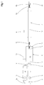
- Fig. 1 illustrated plant for the production of composite pipes has two extruders 1, 2. These are each driven by a variable-speed drive motor 3 or 3a, which - with respect to a conveying direction 4 of the entire system - upstream of the feed hoppers 5 of the extruder 1, 2 is provided.
- a forming machine 6 With reference to the conveying direction 4 downstream of the extruders 1, 2, a forming machine 6, a so-called corrugator, is arranged, to which in turn an aftercooling device 7 is arranged downstream.
- an extruder 1 On an extruder 1, which is arranged in alignment with the molding machine 6 and the aftercooling device 7, a transverse extrusion head 8, that is to say an extrusion tool, is mounted which projects into the molding machine 6.
- the other extruder 2 arranged laterally of this extruder 1 is connected to the transverse extrusion head 8 via an injection channel 9 which opens laterally into the transverse extrusion head 8.
- a composite tube 10 is formed, which emerges in the conveying direction 4 from the molding machine 6 and is cooled in the aftercooling device 7. Behind This aftercooling device 7 can then be cut into pieces of suitable length.
- the molding machine 6 is known in its construction and customary in practice. She is for example in the EP 0 563 575B1 (corresponding U.S. Patent 5,320,797 ), to which reference is expressly made. It essentially has a machine table 11, on which half-molds 12, 12a are arranged. The half-molds 12, 12a are combined on the machine table 11 in the conveying direction 4 each to a mold pair 13 and from - related to the conveying direction 4 - upstream inlet end 14 to the downstream outlet end 15, again in the conveying direction 4 consecutively following mold pairs 13th close to each other.
- the drive of the half-molds 12, 12a, which are brought together in each case on mold sections 16 to mold pairs 13, takes place by means of a drive motor 17.
- the transport of the half-grooves 12, 12a and the mold pairs 13 on the machine table 11 is described in detail in US Pat EP 0 764 516 B1 (corresponding US 5,693,347 ) and described, to which reference may be made.
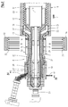
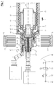
- the cross-spray head 8 has two concentric to a common central longitudinal axis 18 arranged melt channels, namely an inner melt channel 19 and an outer melt channel 20, which - with respect to the conveying direction 4 - downstream in an inner nozzle 21 and an outer nozzle 22 end.
- the inner melt channel 19 is connected to an injection channel 23 of the extruder 1 arranged in alignment with the molding machine 6, whereas the outer melt channel 20 is connected to the injection channel 9 of the other extruder 2.
- a calibration mandrel 25 is attached to this, which also extends concentrically to the axis 18.
- the spray head 8, so the extrusion tool is constructed in many parts.
- the inner melt channel 19 is delimited by an inner nozzle mandrel 26 and an inner nozzle jacket 27.
- the outer melt channel 20 is bounded by an outer nozzle mandrel 28 and an outer nozzle shell 29, wherein the description - with respect to the axis 18 - has taken place from the inside to the outside.
- the half-molds 12, 12a have annular shaped recesses 33, which are arranged at regular intervals one behind the other and which are each connected to partial vacuum channels 34. At the inlet of the half-molds 12, 12a in the molding section 16 reach the partial vacuum channels 34, not shown, in the EP 11 184 779.4 shown and described partial vacuum supply sources, so that the mold recesses 33 are subjected to partial vacuum.
- the spray head 8 supplied plastic melt flows through the outer melt channel 20 to the outer nozzle 22 and is extruded there to form an outer tube 35. Due to the partial vacuum and due to the support air supplied through the support air and vent channel 24, this outer tube 35 defines a shaped with annular wave crests 36 hose into the mold cavities 33. From the extruder 1 is through the spray channel 23 to the transverse Spouthead 8 supplied plastic melt and flows through the inner melt channel 19 to the inner nozzle 21 and exits there as an inner tube 37, which passes to the calibration mandrel 25.
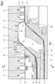
- the half-molds 12, 12a are formed so that in each case at predetermined intervals within the endlessly produced composite pipe 10 connecting sleeves 39 are formed.
- a sleeve recess 40 is formed in a pair of half-molds 12, 12a, which thus has a substantially smooth, cylindrical wall 41.
- a transition surface 42 is formed between the wall 41 of the socket recess 40 and the leading in the conveying direction 4 mold cavity 33.
- the support air and vent channel 24 extends - as Fig. 2 can be removed - over a substantial part of the extension of the spray head 8 in the direction of the axis 18.
- a support air supply pipe 47 a It is connected via a support air line 48 to a compressed air source 49.
- a manually adjustable pressure regulator 50 In the support air line 48 - in this order, starting from the compressed air source 49 - a manually adjustable pressure regulator 50, a controllable solenoid valve 51 and a pressure gauge 52 are arranged. From the support air and vent channel 24 opens a constantly open to the atmosphere vent line 53 from.
- Fig. 5 shows a variant of the embodiment according to Fig. 4 ,
- an air distributor housing 54 is supported by means of a support plate 55 on the spray head 8.
- the air distributor housing 54 opens centrally the support air line 48 a.
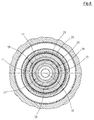
- Fig. 6 As Fig. 6 can be removed, are provided in the support air and venting channel 24 immediately before the exit space 57 between the outer nozzle 22 and inner nozzle 21 more in the present example by 120 ° staggered centering 58 to the outer nozzle mandrel 28 with the radially outboard parts relative to the inner nozzle shell 27 and the parts lying within this support and center.
- centering pieces 58 are to be dimensioned so that a sufficiently large free cross section in the supporting air and venting channel 24, 24 'remains.
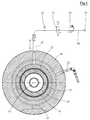
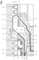
- a modified cross-spray head 8 ' so a modified extrusion tool, shown, which is a so-called star distributor.
- This embodiment is used in particular in the production of pipes with a very large diameter, since in the conventional described embodiment of the spray heads whose weight is too large.
- Such a transverse extrusion head 8 ', as in the Fig. 7 and 8th is shown in the EP 2 116 352B1 shown in detail and described, which may be referred to.
- the parts of the previous description the same parts are designated by the same reference numerals. Functionally identical but structurally different parts are designated by the same reference numerals with a prime, so that a detailed description is not necessary.
- the inner nozzle mandrel 26 ', the inner nozzle casing 27', the outer nozzle mandrel 28 'and the outer nozzle casing 29' are each composed of several parts.
- In the area in front of the outlet space 57 'of the supporting air and venting channel 24' is formed annular cylindrical concentric with the axis 18 and arranged.
- At least one support air feed tube 47 ' extends parallel to the axis through a portion of the crosshead 8', between the inner melt channel 19 'and the outer melt channel 20'.
- the support air supply tube 47 'and the vent line 53' terminate within the crosshead 8 'in an annular disk-shaped distributor channel 59, from which the support air and venting channel 24' opens.
- the minimum gap width a of the ring-cylindrical supporting air and venting channel 24 or 24 ' is to be sized sufficiently large. The following applies: a ⁇ 2.0 mm.
Landscapes
- Engineering & Computer Science (AREA)
- Mechanical Engineering (AREA)
- Manufacturing & Machinery (AREA)
- Physics & Mathematics (AREA)
- Thermal Sciences (AREA)
- Extrusion Moulding Of Plastics Or The Like (AREA)
- Injection Moulding Of Plastics Or The Like (AREA)
Description
- Die Erfindung betrifft eine Vorrichtung nach dem Oberbegriff des Anspruchs 1.
- Eine derartige Vorrichtung ist aus der
EP 2 103 412 A1 (entsprechendUS 2009/0236032 A1 ) bekannt. Hierbei mündet in den Raum zwischen Außen-Düse und Innen-Düse ein Kanal zur Zuführung von Stützluft, wobei die Stützluft zuschaltbar und abschaltbar ist. Aus dem Bereich zwischen Außen-Düse und Innen-Düse mündet wiederum ein gesonderter Entlüftungs-Kanal aus, der ständig zur Atmosphäre offen ist. - Aus der
EP 0 563 575 B1 (entsprechendUS 5 320 797 ) ist eine Vorrichtung ähnlicher Gattung bekannt, bei der das Entlüften jeweils durch Öffnen eines in dem Kanal zur Zuführung von Stützluft angeordneten Magnetventils erfolgt, wobei die Zuführung von Stützluft unterbrochen wird. - Aus der
EP 0 995 579 A2 ist eine Vorrichtung der allgemeinen Gattung bekannt, bei der zwischen der Innen-Düse und der Außen-Düse aus dem Spritzkopf ein Gaskanal ausmündet, der einerseits über ein Ventil an eine Druckgasquelle zum Einblasen von sogenannter Stützluft und andererseits an Atmosphäre anschließbar ist. Ein ständiges Entlüften des Zwischenraumes zwischen und Innen-Schlauch und Außen-Schlauch entsprechend der oben vorausgesetzten Gattung findet hierbei nicht statt. - Aus der
EP 1 612 030 A1 ist eine mit der Vorrichtung nach derEP 0 995 579 A2 gleiche Vorrichtung bekannt. - Aus der
WO 2005/009 720 A1 ist eine Vorrichtung zur Herstellung eines doppelwandigen thermoplastischen Rohres mit einer Rohrmuffe bekannt, bei der zwischen der Innen-Düse und der Außen-Düse ein Stützluft-Kanal aus dem Spritzkopf ausmündet, durch den ständig, also ohne jede Unterbrechung, Stützluft mit einem Druck oberhalb von Atmosphärendruck ausgeblasen wird. Eine Entlüftung findet hierüber nicht statt. - Die Ausgestaltung mit einer ständigen Verbindung zur Atmosphäre hat sich grundsätzlich als vorteilhaft bei der Herstellung von großen Verbundrohren aus Polyolefinen, also Polyethylen und/oder Polypropylen bewiesen. Unter großen Verbundrohren werden hierbei Rohre mit Nennweiten ≥ DN 250 verstanden, wobei die Verbundrohre einfache Verbundrohre und Verbundrohre mit doppellagiger Verbindungsmuffe umfassen.
- Es hat sich aber herausgestellt, dass dieses System noch verbesserungsbedürftig ist.
- Der Erfindung liegt daher die Aufgabe zu Grunde, eine Vorrichtung der eingangs vorausgesetzten Art dahingehend zu verbessern, dass die Steuerung des Luftdrucks im Raum zwischen Außen-Schlauch und Innen-Schlauch mit sehr einfachen Mitteln möglich ist.
- Diese Aufgabe wird erfindungsgemäß bei einer Vorrichtung nach dem Oberbegriff des Anspruches 1 durch die Merkmale in dessen Kennzeichnungsteil gelöst. Durch den groß dimensionierten bzw. dimensionierbaren Stützluft- und Entlüftungs-Kanal ist es möglich, einen entlang der Formstrecke sich verändernden Luftvolumenbedarf zwischen den Schläuchen auf einfache Weise zu kompensieren. Insbesondere bei großen Rohren kommt dies zum Tragen, da bei der Ausformung der Wellenberge größere Stützluft-Volumina erforderlich sind, während bei der Ausformung der Wellentäler, wo der Innen-Schlauch mit dem Außen-Schlauch verschweißt wird, wenig bzw. gar keine Stützluft erforderlich ist. Es kann nicht nur Stützluft zugeführt werden, sondern auch abgeführt werden.
- Besonders vorteilhaft ist die erfindungsgemäße Ausgestaltung, wenn gemäß Anspruch 2 vorgesehen ist, auch doppellagige Verbindungs-Muffen auf der Vorrichtung herzustellen. Hier ist es durch den erfindungsgemäß groß dimensionierten bzw. dimensionierbaren Stützluft- und Entlüftungs-Kanal möglich, einerseits ein schnelles Entlüften an die Atmosphäre andererseits aber auch ein schnelles Zuführen von Atmosphärenluft bei einer pulsierenden Aufweitung des Innenschlauchs zur Verbindungs-Muffe zu erreichen. Dies erfolgt dadurch, dass neben der Stützluft je nach Bedarf mehr oder weniger Umgebungsluft nachströmen kann. Dies ist ein wichtiger Effekt bei leicht schwankenden Werten des Teilvakuums an den Halbkokillen. Dies gilt für die Herstellung der doppellagigen Verbindungs-Muffe, und zwar insbesondere im Hinblick auf die Anforderungen an den Entlüftungsvorgang beim Übergang von der Muffenformung zurück auf die Herstellung des normal gewellten doppelwandigen Verbundrohres. Das System ist sehr stabil. Besondere Abdichtungsmaßnahmen im Bereich des Anfangs des Stützluft- und Entlüftungskanals sind nicht erforderlich, da das gesamte System nicht druckdicht sein muss und demzufolge auch nicht ist. Die Stützluft wird hierbei so bemessen, dass sie die Formgebung durch das Vakuumverfahren bereichsweise unterstützt, jedoch keinen dominierenden Einfluss auf die Formgebung, insbesondere während der Ausformung der doppellagigen Verbindungsmuffe, ausübt.
- Die Unteransprüche geben vorteilhafte Weiterbildungen wider.
- Weitere Einzelheiten, Vorteile und Merkmale ergeben sich aus der nachfolgenden Beschreibung von Ausführungsbeispielen anhand der Zeichnung. Es zeigt:
- Fig. 1
- eine im Wesentlichen aus zwei Extrudern, einer Formmaschine und einer Nachkühlvorrichtung bestehende Anlage zur Herstellung von Verbundrohren mit Verbindungs-Muffen in Draufsicht in schematischer Darstellung,
- Fig. 2
- einen Spritzkopf und das Einlaufende der Formmaschine im Horizontalschnitt,
- Fig. 3
- einen Teilausschnitt aus
Fig. 2 in gegenüberFig. 2 vergrößertem Maßstab, - Fig. 4
- einen Querschnitt durch
Fig. 2 entsprechend der Schnittlinie IV-IV inFig. 2 , - Fig. 5
- eine gegenüber
Fig. 4 abgewandelte Querschnittsdarstellung, - Fig. 6
- einen Querschnitt durch Fig. III, entsprechend der Schnittlinie VI-VI in
Fig. 3 , - Fig. 7
- eine
Fig. 2 entsprechende Darstellung eines abgewandelten Spritzkopfes und - Fig. 8
- eine vergrößerte Teildarstellung aus
Fig. 7 . - Die in
Fig. 1 dargestellte Anlage zur Herstellung von Verbundrohren weist zwei Extruder 1, 2 auf. Diese werden jeweils von einem drehzahlregelbaren Antriebsmotor 3 bzw. 3a angetrieben, der - bezogen auf eine Förderrichtung 4 der gesamten Anlage - stromaufwärts vor den Zuführtrichtern 5 der Extruder 1, 2 vorgesehen ist. - Bezogen auf die Förderrichtung 4 stromabwärts von den Extrudern 1, 2 ist eine Formmaschine 6, ein so genannter Korrugator, angeordnet, dem wiederum eine Nachkühlvorrichtung 7 nachgeordnet ist. An einem fluchtend mit der Formmaschine 6 und der Nachkühlvorrichtung 7 angeordneten Extruder 1 ist ein Quer-Spritzkopf 8 also ein Extrusionswerkzeug angebracht, der in die Formmaschine 6 hineinragt. Der andere, seitlich dieses Extruders 1 angeordnete Extruder 2 ist über einen seitlich in den Quer-Spritzkopf 8 einmündenden Spritzkanal 9 mit dem Quer-Spritzkopf 8 verbunden. Wie schematisch in
Fig. 1 angedeutet ist, wird in der Formmaschine 6 ein Verbundrohr 10 geformt, das in Förderrichtung 4 aus der Formmaschine 6 austritt und in der Nachkühlvorrichtung 7 abgekühlt wird. Hinter dieser Nachkühlvorrichtung 7 kann es dann in Stücke geeigneter Länge zerschnitten werden. - Die Formmaschine 6 ist in ihrem Aufbau bekannt und in der Praxis üblich. Sie ist beispielsweise in der
EP 0 563 575B1 (entsprechendUS-PS 5,320,797 ) beschrieben, worauf ausdrücklich verwiesen wird. Sie weist im Wesentlichen einen Maschinentisch 11 auf, auf dem Halbkokillen 12, 12a angeordnet sind. Die Halbkokillen 12, 12a werden auf dem Maschinentisch 11 in Förderrichtung 4 jeweils zu einem Kokillen-Paar 13 vereinigt und vom - bezogen auf die Förderrichtung 4 - stromaufwärtigen Einlaufende 14 zum stromabwärtigen Auslaufende 15 geführt, wobei wiederum in Förderrichtung 4 hintereinander folgende Kokillen-Paare 13 dicht an dicht liegen. Der Antrieb der auf einer Formstrecke 16 jeweils zu Kokillen-Paaren 13 zusammengeführten Halbkokillen 12, 12a erfolgt mittels eines Antriebsmotors 17. Der Transport der Halbkillen 12, 12a und der Kokillen-Paare 13 auf dem Maschinentisch 11 ist ausführlich in derEP 0 764 516 B1 (entsprechendUS 5 693 347 ) dargestellt und beschrieben, worauf verwiesen werden darf. - Der Quer-Spritzkopf 8 weist zwei konzentrisch zu einer gemeinsamen Mittel-Längs-Achse 18 angeordnete Schmelzekanäle, nämlich einen inneren Schmelzekanal 19 und einen äußeren Schmelzekanal 20, auf, die - bezogen auf die Förderrichtung 4 - stromabwärts in einer Innen-Düse 21 bzw. einer Außen-Düse 22 enden. Der innere Schmelzekanal 19 ist an einen Spritzkanal 23 des fluchtend mit der Formmaschine 6 angeordneten Extruders 1 angeschlossen, wogegen der äußere Schmelzekanal 20 an den Spritzkanal 9 des anderen Extruders 2 angeschlossen ist. Zwischen der Innen-Düse 21 und der Außen-Düse 22 mündet aus dem Spritzkopf 8 ein ringzylindrischer und zur Achse 18 konzentrischer Stützluft- und Entlüftungs-Kanal 24 aus. Am - bezogen auf die Förderrichtung 4 - stromabwärtigen Ende des Spritzkopfes 8 ist an diesem ein Kalibrierdorn 25 angebracht, der ebenfalls konzentrisch zur Achse 18 verläuft.
- Der Spritzkopf 8, also das Extrusionswerkzeug, ist vielteilig aufgebaut. Der innere Schmelzekanal 19 wird von einem Innen-Düsendorn 26 und einem Innen-Düsenmantel 27 begrenzt. Der äußere Schmelzekanal 20 wird von einem Außen-Düsendorn 28 und einem Außen-Düsenmantel 29 begrenzt, wobei die Beschreibung - bezogen auf die Achse 18 - von innen nach außen erfolgt ist. Zwischen dem Innen-Düsenmantel 27 und dem Außen-Düsendorn 28 ist der Stützluft- und Entlüftungs-Kanal 24 ausgebildet und zwar als zur Achse 18 konzentrischer, ringzylindrischer Kanal 24.
- Auf dem Spritzkopf 8, also auf dessen Außen-Düsenmantel 29, ist - bezogen auf die Förderrichtung 4 - stromaufwärts der Außen-Düse 22 eine auswechselbar angebrachte, aus Halbschalen 30 gebildete, zylindrische Außenfläche 31 vorgesehen, zwischen denen und den Halbkokillen 12, 12a ein ringförmiger Dichtspalt 32 gebildet wird. Diese Ausgestaltung ist in der
EP 11 184 779.4 - Die Halbkokillen 12, 12a weisen ringförmige Formausnehmungen 33 auf, die in regelmäßigen Abständen hintereinander angeordnet sind und die jeweils an Teilvakuum-Kanäle 34 angeschlossen sind. Beim Einlauf der Halbkokillen 12, 12a in die Formstrecke 16 gelangen die Teilvakuum-Kanäle 34 an nicht dargestellte, in der
EP 11 184 779.4 - Die vom Extruder 2 durch den Spritzkanal 9 dem Spritzkopf 8 zugeführte Kunststoff-Schmelze strömt durch den äußeren Schmelzekanal 20 zur Außen-Düse 22 und wird dort unter Formung eines Außen-Schlauchs 35 extrudiert. Aufgrund des Teilvakuums und aufgrund von durch den Stützluft- und Entlüftungs-Kanal 24 zugeführter Stützluft legt sich dieser Außen-Schlauch 35 unter Formung eines mit ringförmigen Wellenbergen 36 ausgebildeten Schlauchs in die Formausnehmungen 33. Aus dem Extruder 1 wird durch den Spritzkanal 23 dem Quer-Spritzkopf 8 KunststoffSchmelze zugeführt und strömt durch den inneren Schmelzekanal 19 zur Innen-Düse 21 und tritt dort als Innen-Schlauch 37 aus, der auf den Kalibrier-Dorn 25 gelangt. Dieser erweitert sich von der Innen-Düse 21 in Förderrichtung 4 leicht nach außen, bis der Innen-Schlauch 37 gegen die Wellentäler 38 des Außen-Schlauchs 35 gelangt und hier mit diesem verschweißt wird. Der Innen-Schlauch 37 und der Außen-Schlauch 35 bilden nach Abkühlung unter Erstarrung das Verbundrohr 10.
- Wie insbesondere aus den
Fig. 2 und3 ersichtlich ist, sind die Halbkokillen 12, 12a so ausgebildet, dass jeweils in vorgegebenen Abständen innerhalb des endlos hergestellten Verbundrohres 10 Verbindungs-Muffen 39 ausgebildet werden. Hierzu ist in einem Paar von Halbkokillen 12, 12a eine Muffen-Ausnehmung 40 ausgebildet, die also eine im Wesentlichen glatte, zylindrische Wand 41 aufweist. Zwischen der Wand 41 der Muffen-Ausnehmung 40 und der in Förderrichtung 4 voreilenden Formausnehmung 33 ist eine Übergangs-Fläche 42 ausgebildet. An das - bezogen auf die Förderrichtung 4 - nacheilende Ende der Wand 41 der Muffen-Ausnehmung 40 schließen sich Umfangsrillen 43 zur Versteifung der Verbindungs-Muffe 39 und ein kegelstumpfförmiger Formabschnitt 44 an, in dem ein sich nach außen erweiterndes Einführende 45 der Muffe 39 ausgeformt wird. Daran schließt sich wiederum eine Übergangs-Fläche 46 an, die zur nächsten - in Förderrichtung 4 nacheilenden - Formausnehmung 33 führt. - Der Stützluft- und Entlüftungs-Kanal 24 erstreckt sich - wie
Fig. 2 entnehmbar ist - über einen wesentlichen Teil der Erstreckung des Spritzkopfes 8 in Richtung der Achse 18. Im Bereich des - bezogen auf die Förderrichtung 4 - stromaufwärtigen Endes des Spritzkopfes 8 mündet, wie insbesondereFig. 2 und4 entnehmbar ist, in den Stützluft- und Entlüftungs-Kanal 24 ein Stützluft-Zuführrohr 47 ein. Es ist über eine Stützluft-Leitung 48 mit einer Druckluftquelle 49 verbunden. In der Stützluft-Leitung 48 sind - in dieser Reihenfolge ausgehend von der Druckluftquelle 49 - ein manuell einstellbarer Druckregler 50, ein ansteuerbares Magnetventil 51 und ein Druck-Messgerät 52 angeordnet. Aus dem Stützluft- und Entlüftungs-Kanal 24 mündet eine ständig zur Atmosphäre hin offene Entlüftungs-Leitung 53 aus. -
Fig. 5 zeigt eine Variante zu der Ausgestaltung nachFig. 4 . Hierbei ist ein Luft-Verteiler-Gehäuse 54 mittels eines Tragblechs 55 auf dem Spritzkopf 8 abgestützt. In das Luft-Verteiler-Gehäuse 54 mündet mittig die Stützluft-Leitung 48 ein. Es führen mehrere, im vorliegenden Fall vier Stützluft- und Entlüftungs-Leitungen 56 in den Stützluft- und Entlüftungs-Kanal 24. Aus dem Luft-Verteiler-Gehäuse mündet weiterhin eine zur Atmosphäre hin ständig offene Entlüftungs-Leitung 53 aus. - Wie
Fig. 6 entnehmbar ist, sind im Stützluft- und Entlüftungs-Kanal 24 unmittelbar vor dessen Austritts-Raum 57 zwischen Außen-Düse 22 und Innen-Düse 21 mehrere im vorliegenden Beispiel um 120° gegeneinander versetzte Zentrierstücke 58 vorgesehen, um den Außen-Düsendorn 28 mit den radial außerhalb liegenden Teilen gegenüber dem Innen-Düsenmantel 27 und den innerhalb von diesem liegenden Teilen abzustützen und zu zentrieren. Diese Zentrierstücke 58 sind so zu dimensionieren, dass ein ausreichend großer freier Querschnitt im Stützluft- und Entlüftungs-Kanal 24, 24' verbleibt. - In den
Fig. 7 und8 ist ein abgewandelter Quer-Spritzkopf 8', also ein abgewandeltes Extrusions-Werkzeug, dargestellt, bei dem es sich um einen sogenannten Sternverteiler handelt. Diese Ausgestaltung wird insbesondere bei der Herstellung von Rohren mit sehr großem Durchmesser eingesetzt, da bei der konventionellen geschilderten Ausgestaltung der Spritzköpfe deren Gewicht zu groß wird. Ein solcher Quer-Spritzkopf 8', wie er in denFig. 7 und8 dargestellt ist, ist in derEP 2 116 352B1 im Detail dargestellt und beschrieben, worauf verwiesen werden darf. Im Übrigen werden mit den Teilen der bisherigen Beschreibung gleiche Teile mit gleichen Bezugsziffern bezeichnet. Funktionell gleiche aber konstruktiv andere Teile werden mit denselben Bezugsziffern mit einem hochgesetzten Strich bezeichnet, sodass eine detaillierte Beschreibung nicht notwendig ist. - Der Innen-Düsendorn 26', der Innen-Düsenmantel 27', der Außen-Düsendorn 28' und der Außen-Düsenmantel 29' sind jeweils aus mehreren Teilen zusammengesetzt. Im Bereich vor dem Austritts-Raum 57' ist der Stützluft- und Entlüftungs-Kanal 24' ringzylindrisch konzentrisch zur Achse 18 ausgebildet und angeordnet.
- Mindestens ein Stützluft-Zuführrohr 47' verläuft parallel zur Achse durch einen Teil des Quer-Spritzkopfes 8', und zwar zwischen dem inneren Schmelzekanal 19' und dem äußeren Schmelzekanal 20'. Entsprechend angeordnet ist mindestens eine Entlüftungs-Leitung 53'. Das Stützluft-Zuführrohr 47' und die Entlüftungs-Leitung 53' enden innerhalb des Quer-Spritzkopfes 8' in einem ringscheibenförmigen Verteiler-Kanal 59, aus dem der Stützluft- und Entlüftungs-Kanal 24' ausmündet.
- Die Mindest-Spaltweite a des ringzylindrischen Stützluft- und EntlüftungsKanals 24 bzw. 24' ist ausreichend groß zu bemessen. Es gilt: a ≥ 2,0 mm.
- Während der Produktion des Verbundrohres 10 wird Teilvakuum auf die Teilvakuum-Kanäle 34 aufgebracht, also sowohl auf die Formausnehmungen 33 als auch auf die Muffen-Ausnehmung 40. Während der Herstellung des normalen Verbundrohres 10 mit Wellenbergen 36 wird das Magnetventil 51 geöffnet, sodass von der Druckluftquelle 49 Druckluft mit einem am Druckregler 50 eingestellten Druck über den Stützluft- und Entlüftungs-Kanal 24 bzw. 24' in den Raum 57 zwischen dem Innen-Schlauch 37 und dem Außen-Schlauch 35 eingegeben wird. Da der Kanal 24 bzw. 24' ständig zur Atmosphäre geöffnet ist, stellt sich ein in der Praxis ermittelbarer Stützluft-Druck ein, der deutlich niedriger als der Vordruck in der Stützluft-Leitung 48 ist. Durch das Teilvakuum in den Formausnehmungen 33 und die leichte Unterstützung durch die Stützluft wird der Außen-Schlauch 35 an die Wand der Formausnehmung 33 angelegt und somit der Außen-schlauch ausgeformt. Die jeweils bei der Ausformung eines Wellenberges 36 bzw. eines Wellentales 38 im Außen-Schlauch 35 schwankenden Luftvolumina der Stützluft werden über den Stützluft- und Entlüftungs-Kanal 24 bzw. 24' kompensiert bzw. ausgepuffert. Drucksteuerungseinrichtungen für die Stützluft sind also nicht erforderlich. Die Stützluftzufuhr bleibt aufrecht erhalten, bis die Übergangs-Fläche 42 der Muffen-Ausnehmung 40 die Innen-Düse 21 erreicht, wie es in den
Fig. 2 und3 bzw. 7 und 8 dargestellt ist. Bis zu diesem Zeitpunkt wird der Außen-Schlauch 35 durch das Teilvakuum unterstützt durch den leichten Überdruck der Stützluft an die Wand 41 der Muffen-Ausnehmung 40 angelegt. Dies gilt somit für die Ausformung des Außen-Schlauches 35 zum Verbundrohr 10 und zumindest auch bereichsweise für die Ausformung des Außen-Schlauches 35 zur Verbindungs-Muffe 39. In dem erwähnten inFig. 2 und3 bzw. 7 und 8 dargestellten Zeitpunkt wird das Magnetventil 51 geschlossen, sodass der Raum 57 bzw. 57' über den Stützluft- und Entlüftungs-Kanal 24, 24' entlüftet wird. Gleichzeitig wird über einen zusätzlichen, benachbart zur Innen-Düse 21 angeordneten Gaskanal 60 ein Innendruck auf den Innen-Schlauch 37 gegeben, sodass der Innen-Schlauch 37 an den bereits, zumindest teilweise, an der Wand 41 der Muffen-Ausnehmung 40 anliegenden Außen-Schlauch 35 angelegt wird. Da der Raum 57 bzw. 57' ständig mit der Atmosphäre verbunden ist und keine Stützluft mehr zugeführt wird, herrscht im Raum 57 bzw. 57' Atmosphärendruck. Die in ihm vorhandene Luft wird mit der Aufweitung des Innen-Schlauches 37 bis zur Anlage am Außen-Schlauch 35 aus dem Raum 57 durch den Stützluft- und Entlüftungs-Kanal 24 bzw. 24' verdrängt, also an die Atmosphäre abgegeben. - Der Druckabfall, also der Druckausgleich, von dem leichten Überdruck auf Atmosphärendruck beim Schließen des Magnetventils 51 erfolgt kurzzeitig, d.h. nahezu angenähert schlagartig; das Entlüften des Raums 57 erstreckt sich über den gesamten Zeitraum der Aufweitung des Innen-Schlauches 37 zur Verbindungs-Muffe 39.
Claims (9)
- Vorrichtung zur fortlaufenden Herstellung eines in einer Förderrichtung (4) aus einem glatten Innen-Rohr und einem mit diesem verschweißten, mit Wellenbergen (36) versehenen Außen-Rohr bestehenden Verbundrohres (10) und einer Mittel-Längs-Achse (18)- wobei mit ringförmigen Formausnehmungen (33) versehene, sich auf einer Formstrecke (16) jeweils paarweise zu einer Form mit einer Mittel-Längs-Achse (18) ergänzende Halbkokillen (12, 12a) im Kreislauf und in die Förderrichtung (4) geführt angeordnet sind,- wobei die Formausnehmungen (33) an in den Halbkokillen (12, 12a) ausgebildete Teilvakuum-Kanäle (34) angeschlossen sind,- wobei der Formstrecke (16) ein Spritzkopf (8, 8') mindestens eines Extruders (1, 2) vorgeordnet ist,- wobei der Spritzkopf (8, 8') mit einer Außen-Düse (22) zur Extrusion eines Außen-Schlauches (35) und in Förderrichtung (4) nachgeordnet mit einer Innen-Düse (21) zur Extrusion eines Innen-Schlauches (37) und an seinem in Förderrichtung (4) stromabwärts liegenden Ende mit einem Kalibrierdorn (25) versehen ist,- wobei zwischen Außen-Düse (22) und Innen-Düse (21) aus dem Spritzkopf (8) mindestens ein Stützluft-Kanal (24, 24') ausmündet,
dadurch gekennzeichnet,
dass der Stützluft-Kanal als ständig zur Atmosphäre offener, zumindest benachbart zum Bereich zwischen Innen-Düse (21) und Außen-Düse (22) ringzylindrischer und zur Mittel-Längs-Achse (18) konzentrischer Stützluft- und Entlüftungs-Kanal (24, 24') ausgebildet ist. - Vorrichtung nach Anspruch 1, dadurch gekennzeichnet,
dass zwischen Innen-Düse (21) und Kalibrierdorn (25) mindestens ein zusätzlicher Gas-Kanal (60) aus dem Spritzkopf (8) ausmündet,
dass mindestens ein Paar Halbkokillen (12, 12a) mit einer Muffen-Ausnehmung (40) versehen ist, und
dass die Muffen-Ausnehmung (40) durch eine in Förderrichtung (4) voreilende Übergangs-Fläche (42) begrenzt ist. - Vorrichtung nach Anspruch 1 oder 2, dadurch gekennzeichnet,
dass der Stützluft- und Entlüftungs-Kanal (24) sich über einen wesentlichen Teil der Länge des Spritzkopfes (8) erstreckt. - Vorrichtung nach einem der Ansprüche 1 bis 3, dadurch gekennzeichnet,
dass der Stützluft- und Entlüftungs-Kanal (24, 24') eine Spaltweite a aufweist, für die gilt: a ≥ 2,0 mm. - Vorrichtung nach einem der Ansprüche 1 bis 4, dadurch gekennzeichnet,
dass der Stützluft- und Entlüftungs-Kanal (24, 24') an mindestens ein Stützluft-Zuführrohr (47, 47') angeschlossen ist. - Vorrichtung nach einem der Ansprüche 1 bis 5, dadurch gekennzeichnet,
dass der Stützluft- und Entlüftungs-Kanal (24, 24') an mindestens eine Stützluft-Leitung (48) angeschlossen ist, die an eine Druckluftquelle (49) angeschlossen ist. - Vorrichtung nach einem der Ansprüche 1 bis 6, dadurch gekennzeichnet,
dass dem Stützluft- und Entlüftungs-Kanal (24, 24') ein Druckregler (50), ein Magnetventil (51) und ein Druck-Messgerät (52) vorgeordnet sind. - Vorrichtung nach einem der Ansprüche 1 bis 7, dadurch gekennzeichnet,
dass aus dem Stützluft- und Entlüftungs-Kanal (24, 24') eine ständig zur Atmosphäre offene Entlüftungs-Leitung (53, 53') ausmündet. - Vorrichtung nach einem der Ansprüche 1 bis 7, dadurch gekennzeichnet,
dass dem Stützluft- und Entlüftungs-Kanal (24) ein Luft-Verteiler-Gehäuse (54) vorgeordnet ist, in das eine Stützluft-Leitung (48) einmündet und aus dem eine Entlüftungs-Leitung (53) ausmündet und mit mehreren Stützluft- und Entlüftungs-Leitungen (56) mit dem Stützluft- und Entlüftungs-Kanal (24) verbunden ist.
Priority Applications (5)
| Application Number | Priority Date | Filing Date | Title |
|---|---|---|---|
| EP11187934.2A EP2589481B1 (de) | 2011-11-04 | 2011-11-04 | Vorrichtung zur fortlaufenden Herstellung eines Verbundrohres mit Verbindungs-Muffe |
| PL11187934T PL2589481T3 (pl) | 2011-11-04 | 2011-11-04 | Urządzenie do ciągłego wytwarzania rury wielowarstwowej z kielichem łączącym |
| US13/659,166 US8794948B2 (en) | 2011-11-04 | 2012-10-24 | Apparatus for the continuous production of a twin wall pipe with an integral socket |
| CA2794366A CA2794366C (en) | 2011-11-04 | 2012-10-29 | Apparatus for the continuous production of a twin wall pipe with an integral socket |
| BR102012028016-7A BR102012028016B1 (pt) | 2011-11-04 | 2012-10-31 | dispositivo para a produção contínua de um tubo de parede dupla |
Applications Claiming Priority (1)
| Application Number | Priority Date | Filing Date | Title |
|---|---|---|---|
| EP11187934.2A EP2589481B1 (de) | 2011-11-04 | 2011-11-04 | Vorrichtung zur fortlaufenden Herstellung eines Verbundrohres mit Verbindungs-Muffe |
Publications (2)
| Publication Number | Publication Date |
|---|---|
| EP2589481A1 EP2589481A1 (de) | 2013-05-08 |
| EP2589481B1 true EP2589481B1 (de) | 2016-01-20 |
Family
ID=45509204
Family Applications (1)
| Application Number | Title | Priority Date | Filing Date |
|---|---|---|---|
| EP11187934.2A Active EP2589481B1 (de) | 2011-11-04 | 2011-11-04 | Vorrichtung zur fortlaufenden Herstellung eines Verbundrohres mit Verbindungs-Muffe |
Country Status (5)
| Country | Link |
|---|---|
| US (1) | US8794948B2 (de) |
| EP (1) | EP2589481B1 (de) |
| BR (1) | BR102012028016B1 (de) |
| CA (1) | CA2794366C (de) |
| PL (1) | PL2589481T3 (de) |
Cited By (42)
| Publication number | Priority date | Publication date | Assignee | Title |
|---|---|---|---|---|
| US9840035B2 (en) | 2016-04-15 | 2017-12-12 | Cc3D Llc | Head and system for continuously manufacturing composite hollow structure |
| US10040240B1 (en) | 2017-01-24 | 2018-08-07 | Cc3D Llc | Additive manufacturing system having fiber-cutting mechanism |
| US10081129B1 (en) | 2017-12-29 | 2018-09-25 | Cc3D Llc | Additive manufacturing system implementing hardener pre-impregnation |
| US10105910B2 (en) | 2016-04-15 | 2018-10-23 | Cc3D Llc | Method for continuously manufacturing composite hollow structure |
| US10131088B1 (en) | 2017-12-19 | 2018-11-20 | Cc3D Llc | Additive manufacturing method for discharging interlocking continuous reinforcement |
| US10216165B2 (en) | 2016-09-06 | 2019-02-26 | Cc3D Llc | Systems and methods for controlling additive manufacturing |
| US10319499B1 (en) | 2017-11-30 | 2019-06-11 | Cc3D Llc | System and method for additively manufacturing composite wiring harness |
| US10345068B2 (en) | 2017-02-13 | 2019-07-09 | Cc3D Llc | Composite sporting equipment |
| US10543640B2 (en) | 2016-09-06 | 2020-01-28 | Continuous Composites Inc. | Additive manufacturing system having in-head fiber teasing |
| US10589463B2 (en) | 2017-06-29 | 2020-03-17 | Continuous Composites Inc. | Print head for additive manufacturing system |
| US10603840B2 (en) | 2016-09-06 | 2020-03-31 | Continuous Composites Inc. | Additive manufacturing system having adjustable energy shroud |
| US10625467B2 (en) | 2016-09-06 | 2020-04-21 | Continuous Composites Inc. | Additive manufacturing system having adjustable curing |
| US10717512B2 (en) | 2016-11-03 | 2020-07-21 | Continuous Composites Inc. | Composite vehicle body |
| US10723073B2 (en) | 2017-01-24 | 2020-07-28 | Continuous Composites Inc. | System and method for additively manufacturing a composite structure |
| US10759114B2 (en) | 2017-12-29 | 2020-09-01 | Continuous Composites Inc. | System and print head for continuously manufacturing composite structure |
| US10759113B2 (en) | 2016-09-06 | 2020-09-01 | Continuous Composites Inc. | Additive manufacturing system having trailing cure mechanism |
| US10798783B2 (en) | 2017-02-15 | 2020-10-06 | Continuous Composites Inc. | Additively manufactured composite heater |
| US10814569B2 (en) | 2017-06-29 | 2020-10-27 | Continuous Composites Inc. | Method and material for additive manufacturing |
| US10814604B2 (en) | 2014-07-29 | 2020-10-27 | Continuous Composites Inc. | Method and apparatus for additive mechanical growth of tubular structures |
| US10821720B2 (en) | 2016-11-04 | 2020-11-03 | Continuous Composites Inc. | Additive manufacturing system having gravity-fed matrix |
| US10857729B2 (en) | 2017-12-29 | 2020-12-08 | Continuous Composites Inc. | System and method for additively manufacturing functional elements into existing components |
| US10919222B2 (en) | 2017-12-29 | 2021-02-16 | Continuous Composites Inc. | System and method for additively manufacturing functional elements into existing components |
| US11052603B2 (en) | 2018-06-07 | 2021-07-06 | Continuous Composites Inc. | Additive manufacturing system having stowable cutting mechanism |
| US11110654B2 (en) | 2018-04-12 | 2021-09-07 | Continuous Composites Inc. | System and print head for continuously manufacturing composite structure |
| US11110656B2 (en) | 2018-04-12 | 2021-09-07 | Continuous Composites Inc. | System for continuously manufacturing composite structure |
| US11161300B2 (en) | 2018-04-11 | 2021-11-02 | Continuous Composites Inc. | System and print head for additive manufacturing system |
| US11161297B2 (en) | 2012-08-29 | 2021-11-02 | Continuous Composites Inc. | Control methods for additive manufacturing system |
| US11167495B2 (en) | 2017-12-29 | 2021-11-09 | Continuous Composites Inc. | System and method for additively manufacturing functional elements into existing components |
| US11235539B2 (en) | 2018-09-13 | 2022-02-01 | Continuous Composites Inc. | Fiber management arrangement and method for additive manufacturing system |
| US11247395B2 (en) | 2018-10-26 | 2022-02-15 | Continuous Composites Inc. | System for additive manufacturing |
| US11292192B2 (en) | 2018-11-19 | 2022-04-05 | Continuous Composites Inc. | System for additive manufacturing |
| US11312083B2 (en) | 2019-05-28 | 2022-04-26 | Continuous Composites Inc. | System for additively manufacturing composite structure |
| US11338503B2 (en) | 2019-01-25 | 2022-05-24 | Continuous Composites Inc. | System for additively manufacturing composite structure |
| US11358331B2 (en) | 2018-11-19 | 2022-06-14 | Continuous Composites Inc. | System and head for continuously manufacturing composite structure |
| US11420390B2 (en) | 2018-11-19 | 2022-08-23 | Continuous Composites Inc. | System for additively manufacturing composite structure |
| US11465348B2 (en) | 2020-09-11 | 2022-10-11 | Continuous Composites Inc. | Print head for additive manufacturing system |
| US11752696B2 (en) | 2018-10-04 | 2023-09-12 | Continuous Composites Inc. | System for additively manufacturing composite structures |
| US11760021B2 (en) | 2021-04-27 | 2023-09-19 | Continuous Composites Inc. | Additive manufacturing system |
| US11760030B2 (en) | 2020-06-23 | 2023-09-19 | Continuous Composites Inc. | Systems and methods for controlling additive manufacturing |
| US11840022B2 (en) | 2019-12-30 | 2023-12-12 | Continuous Composites Inc. | System and method for additive manufacturing |
| US11904534B2 (en) | 2020-02-25 | 2024-02-20 | Continuous Composites Inc. | Additive manufacturing system |
| US12128607B2 (en) | 2021-10-20 | 2024-10-29 | Continuous Composites Inc. | Systems and methods for additive manufacturing |
Families Citing this family (8)
| Publication number | Priority date | Publication date | Assignee | Title |
|---|---|---|---|---|
| DE102012022409B3 (de) * | 2012-11-15 | 2013-05-29 | Heinz Gross | Schlauchkopf mit trifunktionellem Bauteil |
| DE102015219221A1 (de) | 2015-10-06 | 2017-04-06 | Ralph Peter Hegler | Spritzkopf für eine Vorrichtung zur Herstellung eines Verbundrohres |
| FR3044867B1 (fr) | 2015-12-09 | 2018-01-26 | S.P.C.M. Sa | Traitement de semences par polymere hydrogonflable |
| CN106003656B (zh) * | 2016-08-05 | 2018-03-06 | 张家港市金达利模塑有限公司 | 双壁波纹管挤出模具 |
| CN106042321B (zh) * | 2016-08-05 | 2018-06-29 | 张家港市金达利模塑有限公司 | 双壁波纹管挤出模具夹层气密闭式独立气道 |
| CN113459463B (zh) * | 2021-07-09 | 2023-03-31 | 泰州长力树脂管有限公司 | 一种pvc管生产设备及其工艺 |
| CN115041685A (zh) * | 2022-05-25 | 2022-09-13 | 邯郸新兴特种管材有限公司 | 一种钼管成型的方法 |
| CN118990890A (zh) * | 2024-08-09 | 2024-11-22 | 徐州众泽机械科技有限公司 | 一种塑料波纹管生产的双层水冷装置 |
Family Cites Families (11)
| Publication number | Priority date | Publication date | Assignee | Title |
|---|---|---|---|---|
| AT325299B (de) * | 1967-02-27 | 1975-10-10 | Hegler Wilhelm | Vorrichtung zur herstellung von rohren aus thermoplastischem kunststoff |
| US5124109A (en) * | 1984-07-18 | 1992-06-23 | Contech Construction Products Inc. | Method for producing a double wall pipe |
| DE4210482A1 (de) | 1992-03-31 | 1993-10-07 | Wilhelm Hegler | Verfahren und Vorrichtung zur fortlaufenden Herstellung eines Verbundrohres mit Rohr-Muffe |
| DE19535231A1 (de) | 1995-09-22 | 1997-03-27 | Hegler Ralph Peter | Vorrichtung zur Herstellung von Rohren aus thermoplastischem Kunststoff mit Querprofilierung |
| DE19848470A1 (de) | 1998-10-21 | 2000-04-27 | Ralph Peter Hegler | Verfahren zur fortlaufenden Herstellung eines Verbundrohres mit einer Rohr-Muffe und Vorrichtung zur Durchführung des Verfahrens |
| US6787092B2 (en) * | 2001-04-06 | 2004-09-07 | Harry Chan | Pipe extrusion die for multi-layer pipe |
| DE10335518A1 (de) * | 2003-07-31 | 2005-02-24 | Manfred Arno Alfred Thornhill Lupke | Vorrichtung zur Herstellung eines doppelwandigen thermoplastischen Rohrs mit einer Rohrmuffe |
| DK1612030T3 (da) * | 2004-07-03 | 2008-01-21 | Ralph-Peter Dr-Ing Hegler | Fremgangsmåde til kontinuerlig fremstilling af et dobbeltvægget korrugeret rör med rörmuffe, det dobbeltvæggede korrugerede rör samt et apparat til udövelse af fremgangsmåden |
| EP2103412B1 (de) | 2008-03-18 | 2013-09-11 | Ralph-Peter Dr.-Ing. Hegler | Verfahren zur fortlaufenden Herstellung eines Verbundrohres mit Rohrmuffe und Vorrichtung zur Durchführung des Verfahrens |
| EP2116352B1 (de) | 2008-05-09 | 2010-06-09 | Ralph-Peter Dr.-Ing. Hegler | Extrusions-Werkzeug für eine Vorrichtung zur Herstellung von Kunststoff-Verbundrohren mit Querrillen |
| DE102010043786B4 (de) | 2010-11-11 | 2013-07-18 | Ralph Peter Hegler | Vorrichtung zur Herstellung von Rohren aus thermoplastischem Kunststoff |
-
2011
- 2011-11-04 PL PL11187934T patent/PL2589481T3/pl unknown
- 2011-11-04 EP EP11187934.2A patent/EP2589481B1/de active Active
-
2012
- 2012-10-24 US US13/659,166 patent/US8794948B2/en not_active Expired - Fee Related
- 2012-10-29 CA CA2794366A patent/CA2794366C/en active Active
- 2012-10-31 BR BR102012028016-7A patent/BR102012028016B1/pt not_active IP Right Cessation
Cited By (119)
| Publication number | Priority date | Publication date | Assignee | Title |
|---|---|---|---|---|
| US11161297B2 (en) | 2012-08-29 | 2021-11-02 | Continuous Composites Inc. | Control methods for additive manufacturing system |
| US10814604B2 (en) | 2014-07-29 | 2020-10-27 | Continuous Composites Inc. | Method and apparatus for additive mechanical growth of tubular structures |
| US10335999B2 (en) | 2016-04-15 | 2019-07-02 | Cc3D Llc | Head and system for continuously manufacturing composite hollow structure |
| US10981327B2 (en) | 2016-04-15 | 2021-04-20 | Continuous Composites Inc. | Head and system for continuously manufacturing composite tube |
| US10105910B2 (en) | 2016-04-15 | 2018-10-23 | Cc3D Llc | Method for continuously manufacturing composite hollow structure |
| US10668663B2 (en) | 2016-04-15 | 2020-06-02 | Continuous Composites Inc. | Head and system for continuously manufacturing composite hollow structure |
| US10213957B2 (en) | 2016-04-15 | 2019-02-26 | Cc3D Llc | Head and system for continuously manufacturing composite hollow structure |
| US9840035B2 (en) | 2016-04-15 | 2017-12-12 | Cc3D Llc | Head and system for continuously manufacturing composite hollow structure |
| US10232551B2 (en) | 2016-04-15 | 2019-03-19 | Cc3D Llc | Head and system for continuously manufacturing composite hollow structure |
| US10272615B2 (en) | 2016-04-15 | 2019-04-30 | Cc3D Llc | Head and system for continuously manufacturing composite hollow structure |
| US10603840B2 (en) | 2016-09-06 | 2020-03-31 | Continuous Composites Inc. | Additive manufacturing system having adjustable energy shroud |
| US10895858B2 (en) | 2016-09-06 | 2021-01-19 | Continuous Composites Inc. | Systems and methods for controlling additive manufacturing |
| US10543640B2 (en) | 2016-09-06 | 2020-01-28 | Continuous Composites Inc. | Additive manufacturing system having in-head fiber teasing |
| US10908576B2 (en) | 2016-09-06 | 2021-02-02 | Continuous Composites Inc. | Systems and methods for controlling additive manufacturing |
| US10216165B2 (en) | 2016-09-06 | 2019-02-26 | Cc3D Llc | Systems and methods for controlling additive manufacturing |
| US10625467B2 (en) | 2016-09-06 | 2020-04-21 | Continuous Composites Inc. | Additive manufacturing system having adjustable curing |
| US10632673B2 (en) | 2016-09-06 | 2020-04-28 | Continuous Composites Inc. | Additive manufacturing system having shutter mechanism |
| US10647058B2 (en) | 2016-09-06 | 2020-05-12 | Continuous Composites Inc. | Control methods for additive manufacturing system |
| US11579579B2 (en) | 2016-09-06 | 2023-02-14 | Continuous Composites Inc. | Systems and methods for controlling additive manufacturing |
| US10901386B2 (en) | 2016-09-06 | 2021-01-26 | Continuous Composites Inc. | Systems and methods for controlling additive manufacturing |
| US10884388B2 (en) | 2016-09-06 | 2021-01-05 | Continuous Composites Inc. | Systems and methods for controlling additive manufacturing |
| US11029658B2 (en) | 2016-09-06 | 2021-06-08 | Continuous Composites Inc. | Systems and methods for controlling additive manufacturing |
| US10759113B2 (en) | 2016-09-06 | 2020-09-01 | Continuous Composites Inc. | Additive manufacturing system having trailing cure mechanism |
| US10864715B2 (en) | 2016-09-06 | 2020-12-15 | Continuous Composites Inc. | Additive manufacturing system having multi-channel nozzle |
| US10766191B2 (en) | 2016-09-06 | 2020-09-08 | Continuous Composites Inc. | Additive manufacturing system having in-head fiber weaving |
| US11000998B2 (en) | 2016-09-06 | 2021-05-11 | Continous Composites Inc. | Additive manufacturing system having in-head fiber-teasing |
| US12228901B2 (en) | 2016-09-06 | 2025-02-18 | Continuos Composites Inc. | Systems and methods for controlling additive manufacturing |
| US10994481B2 (en) | 2016-09-06 | 2021-05-04 | Continuous Composites Inc. | Additive manufacturing system having in-head fiber-teasing |
| US10787240B2 (en) | 2016-11-03 | 2020-09-29 | Continuous Composites Inc. | Composite vehicle body |
| US10766595B2 (en) | 2016-11-03 | 2020-09-08 | Continuous Composites Inc. | Composite vehicle body |
| US11383819B2 (en) | 2016-11-03 | 2022-07-12 | Continuous Composites Inc. | Composite vehicle body |
| US10773783B2 (en) | 2016-11-03 | 2020-09-15 | Continuous Composites Inc. | Composite vehicle body |
| US10717512B2 (en) | 2016-11-03 | 2020-07-21 | Continuous Composites Inc. | Composite vehicle body |
| US10967569B2 (en) | 2016-11-04 | 2021-04-06 | Continuous Composites Inc. | Additive manufacturing system having interchangeable nozzle tips |
| US10953598B2 (en) | 2016-11-04 | 2021-03-23 | Continuous Composites Inc. | Additive manufacturing system having vibrating nozzle |
| US10821720B2 (en) | 2016-11-04 | 2020-11-03 | Continuous Composites Inc. | Additive manufacturing system having gravity-fed matrix |
| US10828829B2 (en) | 2016-11-04 | 2020-11-10 | Continuous Composites Inc. | Additive manufacturing system having adjustable nozzle configuration |
| US10843406B2 (en) | 2016-11-04 | 2020-11-24 | Continuous Composites Inc. | Additive manufacturing system having multi-flex nozzle |
| US10933584B2 (en) | 2016-11-04 | 2021-03-02 | Continuous Composites Inc. | Additive manufacturing system having dynamically variable matrix supply |
| US10864677B2 (en) | 2016-11-04 | 2020-12-15 | Continuous Composites Inc. | Additive manufacturing system implementing in-situ anchor-point fabrication |
| US10723073B2 (en) | 2017-01-24 | 2020-07-28 | Continuous Composites Inc. | System and method for additively manufacturing a composite structure |
| US11014290B2 (en) | 2017-01-24 | 2021-05-25 | Continuous Composites Inc. | Additive manufacturing system having automated reinforcement threading |
| US10857726B2 (en) | 2017-01-24 | 2020-12-08 | Continuous Composites Inc. | Additive manufacturing system implementing anchor curing |
| US10850445B2 (en) | 2017-01-24 | 2020-12-01 | Continuous Composites Inc. | Additive manufacturing system configured for sheet-printing composite material |
| US10040240B1 (en) | 2017-01-24 | 2018-08-07 | Cc3D Llc | Additive manufacturing system having fiber-cutting mechanism |
| US10919204B2 (en) | 2017-01-24 | 2021-02-16 | Continuous Composites Inc. | Continuous reinforcement for use in additive manufacturing |
| US10843396B2 (en) | 2017-01-24 | 2020-11-24 | Continuous Composites Inc. | Additive manufacturing system |
| US10940638B2 (en) | 2017-01-24 | 2021-03-09 | Continuous Composites Inc. | Additive manufacturing system having finish-follower |
| US10345068B2 (en) | 2017-02-13 | 2019-07-09 | Cc3D Llc | Composite sporting equipment |
| US10794650B2 (en) | 2017-02-13 | 2020-10-06 | Continuous Composites | Composite sporting equipment |
| US10993289B2 (en) | 2017-02-15 | 2021-04-27 | Continuous Composites Inc. | Additive manufacturing system for fabricating custom support structure |
| US10932325B2 (en) | 2017-02-15 | 2021-02-23 | Continuous Composites Inc. | Additive manufacturing system and method for discharging coated continuous composites |
| US10798783B2 (en) | 2017-02-15 | 2020-10-06 | Continuous Composites Inc. | Additively manufactured composite heater |
| US10814569B2 (en) | 2017-06-29 | 2020-10-27 | Continuous Composites Inc. | Method and material for additive manufacturing |
| US11130285B2 (en) | 2017-06-29 | 2021-09-28 | Continuous Composites Inc. | Print head and method for printing composite structure and temporary support |
| US10906240B2 (en) | 2017-06-29 | 2021-02-02 | Continuous Composites Inc. | Print head for additive manufacturing system |
| US10589463B2 (en) | 2017-06-29 | 2020-03-17 | Continuous Composites Inc. | Print head for additive manufacturing system |
| US11052602B2 (en) | 2017-06-29 | 2021-07-06 | Continuous Composites Inc. | Print head for additively manufacturing composite tubes |
| US11135769B2 (en) | 2017-06-29 | 2021-10-05 | Continuous Composites Inc. | In-situ curing oven for additive manufacturing system |
| US10319499B1 (en) | 2017-11-30 | 2019-06-11 | Cc3D Llc | System and method for additively manufacturing composite wiring harness |
| US10131088B1 (en) | 2017-12-19 | 2018-11-20 | Cc3D Llc | Additive manufacturing method for discharging interlocking continuous reinforcement |
| US10919222B2 (en) | 2017-12-29 | 2021-02-16 | Continuous Composites Inc. | System and method for additively manufacturing functional elements into existing components |
| US10759114B2 (en) | 2017-12-29 | 2020-09-01 | Continuous Composites Inc. | System and print head for continuously manufacturing composite structure |
| US10857729B2 (en) | 2017-12-29 | 2020-12-08 | Continuous Composites Inc. | System and method for additively manufacturing functional elements into existing components |
| US11623394B2 (en) | 2017-12-29 | 2023-04-11 | Continuous Composites Inc. | System, print head, and compactor for continuously manufacturing composite structure |
| US10807303B2 (en) | 2017-12-29 | 2020-10-20 | Continuous Composites, Inc. | Additive manufacturing system implementing hardener pre-impregnation |
| US11135770B2 (en) | 2017-12-29 | 2021-10-05 | Continuous Composites Inc. | System for continuously manufacturing composite structure |
| US11135764B2 (en) | 2017-12-29 | 2021-10-05 | Continuous Composites Inc. | Additive manufacturing system implementing hardener pre-impregnation |
| US10081129B1 (en) | 2017-12-29 | 2018-09-25 | Cc3D Llc | Additive manufacturing system implementing hardener pre-impregnation |
| US11110655B2 (en) | 2017-12-29 | 2021-09-07 | Continuous Composites Inc. | System, print head, and compactor for continuously manufacturing composite structure |
| US11623393B2 (en) | 2017-12-29 | 2023-04-11 | Continuous Composites Inc. | System, print head, and compactor for continuously manufacturing composite structure |
| US11167495B2 (en) | 2017-12-29 | 2021-11-09 | Continuous Composites Inc. | System and method for additively manufacturing functional elements into existing components |
| US11161300B2 (en) | 2018-04-11 | 2021-11-02 | Continuous Composites Inc. | System and print head for additive manufacturing system |
| US11958243B2 (en) | 2018-04-12 | 2024-04-16 | Continuous Composites Inc. | System for continuously manufacturing composite structure |
| US11130284B2 (en) | 2018-04-12 | 2021-09-28 | Continuous Composites Inc. | System and head for continuously manufacturing composite structure |
| US11110654B2 (en) | 2018-04-12 | 2021-09-07 | Continuous Composites Inc. | System and print head for continuously manufacturing composite structure |
| US11110656B2 (en) | 2018-04-12 | 2021-09-07 | Continuous Composites Inc. | System for continuously manufacturing composite structure |
| US11052603B2 (en) | 2018-06-07 | 2021-07-06 | Continuous Composites Inc. | Additive manufacturing system having stowable cutting mechanism |
| US11235539B2 (en) | 2018-09-13 | 2022-02-01 | Continuous Composites Inc. | Fiber management arrangement and method for additive manufacturing system |
| US11338528B2 (en) | 2018-09-13 | 2022-05-24 | Continouos Composites Inc. | System for additively manufacturing composite structures |
| US11752696B2 (en) | 2018-10-04 | 2023-09-12 | Continuous Composites Inc. | System for additively manufacturing composite structures |
| US11760013B2 (en) | 2018-10-04 | 2023-09-19 | Continuous Composites Inc. | System for additively manufacturing composite structures |
| US11787112B2 (en) | 2018-10-04 | 2023-10-17 | Continuous Composites Inc. | System for additively manufacturing composite structures |
| US11806923B2 (en) | 2018-10-26 | 2023-11-07 | Continuous Composites Inc. | System for additive manufacturing |
| US11279085B2 (en) | 2018-10-26 | 2022-03-22 | Continuous Composites Inc. | System for additive manufacturing |
| US11607839B2 (en) | 2018-10-26 | 2023-03-21 | Continuous Composites Inc. | System for additive manufacturing |
| US11325304B2 (en) | 2018-10-26 | 2022-05-10 | Continuous Composites Inc. | System and method for additive manufacturing |
| US11511480B2 (en) | 2018-10-26 | 2022-11-29 | Continuous Composites Inc. | System for additive manufacturing |
| US11247395B2 (en) | 2018-10-26 | 2022-02-15 | Continuous Composites Inc. | System for additive manufacturing |
| US11420390B2 (en) | 2018-11-19 | 2022-08-23 | Continuous Composites Inc. | System for additively manufacturing composite structure |
| US11292192B2 (en) | 2018-11-19 | 2022-04-05 | Continuous Composites Inc. | System for additive manufacturing |
| US11358331B2 (en) | 2018-11-19 | 2022-06-14 | Continuous Composites Inc. | System and head for continuously manufacturing composite structure |
| US12128615B2 (en) | 2018-11-19 | 2024-10-29 | Continuous Composites Inc. | System for additive manufacturing |
| US11485070B2 (en) | 2019-01-25 | 2022-11-01 | Continuous Composites Inc. | System for additively manufacturing composite structure |
| US11478980B2 (en) | 2019-01-25 | 2022-10-25 | Continuous Composites Inc. | System for additively manufacturing composite structure |
| US11618208B2 (en) | 2019-01-25 | 2023-04-04 | Continuous Composites Inc. | System for additively manufacturing composite structure |
| US11400643B2 (en) | 2019-01-25 | 2022-08-02 | Continuous Composites Inc. | System for additively manufacturing composite structure |
| US11338503B2 (en) | 2019-01-25 | 2022-05-24 | Continuous Composites Inc. | System for additively manufacturing composite structure |
| US11541603B2 (en) | 2019-05-28 | 2023-01-03 | Continuous Composites Inc. | System for additively manufacturing composite structure |
| US11312083B2 (en) | 2019-05-28 | 2022-04-26 | Continuous Composites Inc. | System for additively manufacturing composite structure |
| US11958245B2 (en) | 2019-05-28 | 2024-04-16 | Continuous Composites Inc. | System for additively manufacturing composite structure |
| US11840022B2 (en) | 2019-12-30 | 2023-12-12 | Continuous Composites Inc. | System and method for additive manufacturing |
| US11904534B2 (en) | 2020-02-25 | 2024-02-20 | Continuous Composites Inc. | Additive manufacturing system |
| US11760030B2 (en) | 2020-06-23 | 2023-09-19 | Continuous Composites Inc. | Systems and methods for controlling additive manufacturing |
| US11760029B2 (en) | 2020-06-23 | 2023-09-19 | Continuous Composites Inc. | Systems and methods for controlling additive manufacturing |
| US12128630B2 (en) | 2020-06-23 | 2024-10-29 | Continuous Composites Inc. | Systems and methods for controlling additive manufacturing |
| US11926100B2 (en) | 2020-06-23 | 2024-03-12 | Continuous Composites Inc. | Systems and methods for controlling additive manufacturing |
| US11613080B2 (en) | 2020-09-11 | 2023-03-28 | Continuous Composites Inc. | Print head for additive manufacturing system |
| US11813793B2 (en) | 2020-09-11 | 2023-11-14 | Continuous Composites Inc. | Print head for additive manufacturing system |
| US12083741B2 (en) | 2020-09-11 | 2024-09-10 | Continous Composites Inc. | Print heads for additive manufacturing systems |
| US11465348B2 (en) | 2020-09-11 | 2022-10-11 | Continuous Composites Inc. | Print head for additive manufacturing system |
| US11541598B2 (en) | 2020-09-11 | 2023-01-03 | Continuous Composites Inc. | Print head for additive manufacturing system |
| US12290985B2 (en) | 2020-09-11 | 2025-05-06 | Continuous Composites Inc. | Print head for additive manufacturing system |
| US12290983B2 (en) | 2020-09-11 | 2025-05-06 | Continuous Composites Inc. | Print head for additive manufacturing system |
| US11958247B2 (en) | 2021-04-27 | 2024-04-16 | Continuous Composites Inc. | Additive manufacturing system |
| US12030252B2 (en) | 2021-04-27 | 2024-07-09 | Continuous Composites Inc. | Additive manufacturing system |
| US11760021B2 (en) | 2021-04-27 | 2023-09-19 | Continuous Composites Inc. | Additive manufacturing system |
| US12128607B2 (en) | 2021-10-20 | 2024-10-29 | Continuous Composites Inc. | Systems and methods for additive manufacturing |
| US12134226B2 (en) | 2021-10-20 | 2024-11-05 | Continuous Composites Inc. | Systems and methods of additive manufacturing |
Also Published As
| Publication number | Publication date |
|---|---|
| US20130115324A1 (en) | 2013-05-09 |
| BR102012028016A8 (pt) | 2018-05-15 |
| BR102012028016B1 (pt) | 2021-01-05 |
| CA2794366C (en) | 2019-06-04 |
| CA2794366A1 (en) | 2013-05-04 |
| BR102012028016A2 (pt) | 2014-10-29 |
| EP2589481A1 (de) | 2013-05-08 |
| US8794948B2 (en) | 2014-08-05 |
| PL2589481T3 (pl) | 2016-06-30 |
Similar Documents
| Publication | Publication Date | Title |
|---|---|---|
| EP2589481B1 (de) | Vorrichtung zur fortlaufenden Herstellung eines Verbundrohres mit Verbindungs-Muffe | |
| EP0995579B1 (de) | Verfahren zur fortlaufenden Herstellung eines Verbundrohres mit einer Rohr-Muffe und Vorrichtung zur Durchführung des Verfahrens | |
| EP1612030B1 (de) | Verfahren zur fortlaufenden Herstellung eines Doppelwand-Wellrohres mit Rohrmuffe, das Doppelwand-Wellrohr und die Vorrichtung zur Durchführung des Verfahrens | |
| DE19835189A1 (de) | Vorrichtung zur kontinuierlichen Herstellung von nahtlosen Kunststoffrohren | |
| DE2403618A1 (de) | Vorrichtung zum herstellen eines doppelwandigen kunststoffrohres | |
| EP2125329B1 (de) | Verfahren und vorrichtung zur fortlaufenden herstellung eines kunststoff-verbundrohres mit rohrmuffe | |
| EP2452803B1 (de) | Vorrichtung zur Herstellung von Wellrohren aus thermoplastischem Kunststoff | |
| EP1115551B1 (de) | Vorrichtung und verfahren zur herstellung von kunststoffrohren | |
| DE202007016630U1 (de) | Vorrichtung zur fortlaufenden Herstellung eines Verbundrohres mit Rohrmuffe | |
| DE102009027437B4 (de) | Vorrichtung und Verfahren zum Kühlen von Kunststoffprofilen | |
| DE1504253B2 (de) | Laengsspritzkopf mit dorn zum herstellen von hohlprofilen | |
| DE19843341A1 (de) | Vorrichtung zur Herstellung von Kunststoffrohren | |
| EP1914060A2 (de) | Vorrichtung zum Extrudieren von Hohlsträngen | |
| EP3153296B1 (de) | Spritzkopf für eine vorrichtung zur herstellung eines verbundrohres | |
| EP2252449B1 (de) | Verfahren und vorrichtung zur fortlaufenden herstellung eines verbundrohres mit rohrmuffe und verbundrohr | |
| DE102006048512B4 (de) | Vorrichtung zur Herstellung von Verbund-Rohren | |
| EP4434716A1 (de) | Kunststoffrohr und vorrichtung zur kontinuierlichen herstellung eines rohrgrundkörpers für ein derartiges kunststoffrohr | |
| EP2425958B1 (de) | Vorrichtung zur fortlaufenden Herstellung eines Verbundrohres mit einer Rohrmuffe | |
| EP1923199A2 (de) | Vorrichtung zum Extrudieren von Hohlsträngen | |
| EP2436504B1 (de) | Verfahren zur fortlaufenden Herstellung eines Verbundrohres mit Rohrmuffe, Verbundrohr mit Rohrmuffe und Vorrichtung zur Durchführung des Verfahrens und zur Herstellung des Verbundrohres | |
| DE202008018223U1 (de) | Vorrichtung zur fortlaufenden Herstellung einesVerbundrohres mit Rohrmuffe | |
| WO2010029142A2 (de) | Vorrichtung und verfahren zum kühlen von kunststoffprofilen | |
| DE3426680C2 (de) | ||
| DE202004019566U1 (de) | Führungskammer als Anfahrhilfe | |
| EP0243516A1 (de) | Vorrichtung zum Extrudieren eines doppelwandigen Kunststoffrohres |
Legal Events
| Date | Code | Title | Description |
|---|---|---|---|
| PUAI | Public reference made under article 153(3) epc to a published international application that has entered the european phase |
Free format text: ORIGINAL CODE: 0009012 |
|
| AK | Designated contracting states |
Kind code of ref document: A1 Designated state(s): AL AT BE BG CH CY CZ DE DK EE ES FI FR GB GR HR HU IE IS IT LI LT LU LV MC MK MT NL NO PL PT RO RS SE SI SK SM TR |
|
| AX | Request for extension of the european patent |
Extension state: BA ME |
|
| 17P | Request for examination filed |
Effective date: 20131104 |
|
| RBV | Designated contracting states (corrected) |
Designated state(s): AL AT BE BG CH CY CZ DE DK EE ES FI FR GB GR HR HU IE IS IT LI LT LU LV MC MK MT NL NO PL PT RO RS SE SI SK SM TR |
|
| GRAP | Despatch of communication of intention to grant a patent |
Free format text: ORIGINAL CODE: EPIDOSNIGR1 |
|
| RIC1 | Information provided on ipc code assigned before grant |
Ipc: B29C 47/12 20060101AFI20150918BHEP Ipc: B29C 47/92 20060101ALI20150918BHEP Ipc: B29C 47/06 20060101ALN20150918BHEP Ipc: B29C 49/00 20060101ALN20150918BHEP |
|
| INTG | Intention to grant announced |
Effective date: 20151009 |
|
| GRAS | Grant fee paid |
Free format text: ORIGINAL CODE: EPIDOSNIGR3 |
|
| GRAA | (expected) grant |
Free format text: ORIGINAL CODE: 0009210 |
|
| AK | Designated contracting states |
Kind code of ref document: B1 Designated state(s): AL AT BE BG CH CY CZ DE DK EE ES FI FR GB GR HR HU IE IS IT LI LT LU LV MC MK MT NL NO PL PT RO RS SE SI SK SM TR |
|
| REG | Reference to a national code |
Ref country code: GB Ref legal event code: FG4D Free format text: NOT ENGLISH |
|
| REG | Reference to a national code |
Ref country code: CH Ref legal event code: EP |
|
| REG | Reference to a national code |
Ref country code: IE Ref legal event code: FG4D Free format text: LANGUAGE OF EP DOCUMENT: GERMAN |
|
| REG | Reference to a national code |
Ref country code: AT Ref legal event code: REF Ref document number: 771488 Country of ref document: AT Kind code of ref document: T Effective date: 20160215 |
|
| REG | Reference to a national code |
Ref country code: DE Ref legal event code: R096 Ref document number: 502011008699 Country of ref document: DE |
|
| REG | Reference to a national code |
Ref country code: LT Ref legal event code: MG4D Ref country code: NL Ref legal event code: MP Effective date: 20160120 |
|
| PG25 | Lapsed in a contracting state [announced via postgrant information from national office to epo] |
Ref country code: NL Free format text: LAPSE BECAUSE OF FAILURE TO SUBMIT A TRANSLATION OF THE DESCRIPTION OR TO PAY THE FEE WITHIN THE PRESCRIBED TIME-LIMIT Effective date: 20160120 |
|
| PG25 | Lapsed in a contracting state [announced via postgrant information from national office to epo] |
Ref country code: GR Free format text: LAPSE BECAUSE OF FAILURE TO SUBMIT A TRANSLATION OF THE DESCRIPTION OR TO PAY THE FEE WITHIN THE PRESCRIBED TIME-LIMIT Effective date: 20160421 Ref country code: NO Free format text: LAPSE BECAUSE OF FAILURE TO SUBMIT A TRANSLATION OF THE DESCRIPTION OR TO PAY THE FEE WITHIN THE PRESCRIBED TIME-LIMIT Effective date: 20160420 Ref country code: ES Free format text: LAPSE BECAUSE OF FAILURE TO SUBMIT A TRANSLATION OF THE DESCRIPTION OR TO PAY THE FEE WITHIN THE PRESCRIBED TIME-LIMIT Effective date: 20160120 Ref country code: IT Free format text: LAPSE BECAUSE OF FAILURE TO SUBMIT A TRANSLATION OF THE DESCRIPTION OR TO PAY THE FEE WITHIN THE PRESCRIBED TIME-LIMIT Effective date: 20160120 Ref country code: HR Free format text: LAPSE BECAUSE OF FAILURE TO SUBMIT A TRANSLATION OF THE DESCRIPTION OR TO PAY THE FEE WITHIN THE PRESCRIBED TIME-LIMIT Effective date: 20160120 Ref country code: FI Free format text: LAPSE BECAUSE OF FAILURE TO SUBMIT A TRANSLATION OF THE DESCRIPTION OR TO PAY THE FEE WITHIN THE PRESCRIBED TIME-LIMIT Effective date: 20160120 |
|
| PG25 | Lapsed in a contracting state [announced via postgrant information from national office to epo] |
Ref country code: PT Free format text: LAPSE BECAUSE OF FAILURE TO SUBMIT A TRANSLATION OF THE DESCRIPTION OR TO PAY THE FEE WITHIN THE PRESCRIBED TIME-LIMIT Effective date: 20160520 Ref country code: SE Free format text: LAPSE BECAUSE OF FAILURE TO SUBMIT A TRANSLATION OF THE DESCRIPTION OR TO PAY THE FEE WITHIN THE PRESCRIBED TIME-LIMIT Effective date: 20160120 Ref country code: LT Free format text: LAPSE BECAUSE OF FAILURE TO SUBMIT A TRANSLATION OF THE DESCRIPTION OR TO PAY THE FEE WITHIN THE PRESCRIBED TIME-LIMIT Effective date: 20160120 Ref country code: IS Free format text: LAPSE BECAUSE OF FAILURE TO SUBMIT A TRANSLATION OF THE DESCRIPTION OR TO PAY THE FEE WITHIN THE PRESCRIBED TIME-LIMIT Effective date: 20160520 Ref country code: RS Free format text: LAPSE BECAUSE OF FAILURE TO SUBMIT A TRANSLATION OF THE DESCRIPTION OR TO PAY THE FEE WITHIN THE PRESCRIBED TIME-LIMIT Effective date: 20160120 Ref country code: LV Free format text: LAPSE BECAUSE OF FAILURE TO SUBMIT A TRANSLATION OF THE DESCRIPTION OR TO PAY THE FEE WITHIN THE PRESCRIBED TIME-LIMIT Effective date: 20160120 |
|
| REG | Reference to a national code |
Ref country code: DE Ref legal event code: R097 Ref document number: 502011008699 Country of ref document: DE |
|
| PG25 | Lapsed in a contracting state [announced via postgrant information from national office to epo] |
Ref country code: DK Free format text: LAPSE BECAUSE OF FAILURE TO SUBMIT A TRANSLATION OF THE DESCRIPTION OR TO PAY THE FEE WITHIN THE PRESCRIBED TIME-LIMIT Effective date: 20160120 Ref country code: EE Free format text: LAPSE BECAUSE OF FAILURE TO SUBMIT A TRANSLATION OF THE DESCRIPTION OR TO PAY THE FEE WITHIN THE PRESCRIBED TIME-LIMIT Effective date: 20160120 |
|
| REG | Reference to a national code |
Ref country code: FR Ref legal event code: PLFP Year of fee payment: 6 |
|
| PLBE | No opposition filed within time limit |
Free format text: ORIGINAL CODE: 0009261 |
|
| STAA | Information on the status of an ep patent application or granted ep patent |
Free format text: STATUS: NO OPPOSITION FILED WITHIN TIME LIMIT |
|
| PG25 | Lapsed in a contracting state [announced via postgrant information from national office to epo] |
Ref country code: CZ Free format text: LAPSE BECAUSE OF FAILURE TO SUBMIT A TRANSLATION OF THE DESCRIPTION OR TO PAY THE FEE WITHIN THE PRESCRIBED TIME-LIMIT Effective date: 20160120 Ref country code: RO Free format text: LAPSE BECAUSE OF FAILURE TO SUBMIT A TRANSLATION OF THE DESCRIPTION OR TO PAY THE FEE WITHIN THE PRESCRIBED TIME-LIMIT Effective date: 20160120 Ref country code: SK Free format text: LAPSE BECAUSE OF FAILURE TO SUBMIT A TRANSLATION OF THE DESCRIPTION OR TO PAY THE FEE WITHIN THE PRESCRIBED TIME-LIMIT Effective date: 20160120 Ref country code: SM Free format text: LAPSE BECAUSE OF FAILURE TO SUBMIT A TRANSLATION OF THE DESCRIPTION OR TO PAY THE FEE WITHIN THE PRESCRIBED TIME-LIMIT Effective date: 20160120 |
|
| 26N | No opposition filed |
Effective date: 20161021 |
|
| PG25 | Lapsed in a contracting state [announced via postgrant information from national office to epo] |
Ref country code: BE Free format text: LAPSE BECAUSE OF NON-PAYMENT OF DUE FEES Effective date: 20161130 Ref country code: BG Free format text: LAPSE BECAUSE OF FAILURE TO SUBMIT A TRANSLATION OF THE DESCRIPTION OR TO PAY THE FEE WITHIN THE PRESCRIBED TIME-LIMIT Effective date: 20160420 Ref country code: SI Free format text: LAPSE BECAUSE OF FAILURE TO SUBMIT A TRANSLATION OF THE DESCRIPTION OR TO PAY THE FEE WITHIN THE PRESCRIBED TIME-LIMIT Effective date: 20160120 |
|
| REG | Reference to a national code |
Ref country code: CH Ref legal event code: PL |
|
| PG25 | Lapsed in a contracting state [announced via postgrant information from national office to epo] |
Ref country code: LI Free format text: LAPSE BECAUSE OF NON-PAYMENT OF DUE FEES Effective date: 20161130 Ref country code: CH Free format text: LAPSE BECAUSE OF NON-PAYMENT OF DUE FEES Effective date: 20161130 |
|
| REG | Reference to a national code |
Ref country code: IE Ref legal event code: MM4A |
|
| PG25 | Lapsed in a contracting state [announced via postgrant information from national office to epo] |
Ref country code: LU Free format text: LAPSE BECAUSE OF NON-PAYMENT OF DUE FEES Effective date: 20161130 |
|
| REG | Reference to a national code |
Ref country code: FR Ref legal event code: PLFP Year of fee payment: 7 |
|
| PG25 | Lapsed in a contracting state [announced via postgrant information from national office to epo] |
Ref country code: IE Free format text: LAPSE BECAUSE OF NON-PAYMENT OF DUE FEES Effective date: 20161104 |
|
| REG | Reference to a national code |
Ref country code: AT Ref legal event code: MM01 Ref document number: 771488 Country of ref document: AT Kind code of ref document: T Effective date: 20161104 |
|
| PG25 | Lapsed in a contracting state [announced via postgrant information from national office to epo] |
Ref country code: AT Free format text: LAPSE BECAUSE OF NON-PAYMENT OF DUE FEES Effective date: 20161104 |
|
| REG | Reference to a national code |
Ref country code: BE Ref legal event code: MM Effective date: 20161130 |
|
| PG25 | Lapsed in a contracting state [announced via postgrant information from national office to epo] |
Ref country code: PL Free format text: LAPSE BECAUSE OF NON-PAYMENT OF DUE FEES Effective date: 20161104 |
|
| PG25 | Lapsed in a contracting state [announced via postgrant information from national office to epo] |
Ref country code: CY Free format text: LAPSE BECAUSE OF FAILURE TO SUBMIT A TRANSLATION OF THE DESCRIPTION OR TO PAY THE FEE WITHIN THE PRESCRIBED TIME-LIMIT Effective date: 20160120 Ref country code: HU Free format text: LAPSE BECAUSE OF FAILURE TO SUBMIT A TRANSLATION OF THE DESCRIPTION OR TO PAY THE FEE WITHIN THE PRESCRIBED TIME-LIMIT; INVALID AB INITIO Effective date: 20111104 |
|
| PG25 | Lapsed in a contracting state [announced via postgrant information from national office to epo] |
Ref country code: MC Free format text: LAPSE BECAUSE OF FAILURE TO SUBMIT A TRANSLATION OF THE DESCRIPTION OR TO PAY THE FEE WITHIN THE PRESCRIBED TIME-LIMIT Effective date: 20160120 Ref country code: MK Free format text: LAPSE BECAUSE OF FAILURE TO SUBMIT A TRANSLATION OF THE DESCRIPTION OR TO PAY THE FEE WITHIN THE PRESCRIBED TIME-LIMIT Effective date: 20160120 |
|
| PG25 | Lapsed in a contracting state [announced via postgrant information from national office to epo] |
Ref country code: MT Free format text: LAPSE BECAUSE OF FAILURE TO SUBMIT A TRANSLATION OF THE DESCRIPTION OR TO PAY THE FEE WITHIN THE PRESCRIBED TIME-LIMIT Effective date: 20160120 |
|
| PG25 | Lapsed in a contracting state [announced via postgrant information from national office to epo] |
Ref country code: AL Free format text: LAPSE BECAUSE OF FAILURE TO SUBMIT A TRANSLATION OF THE DESCRIPTION OR TO PAY THE FEE WITHIN THE PRESCRIBED TIME-LIMIT Effective date: 20160120 |
|
| REG | Reference to a national code |
Ref country code: DE Ref legal event code: R079 Ref document number: 502011008699 Country of ref document: DE Free format text: PREVIOUS MAIN CLASS: B29C0047120000 Ipc: B29C0048300000 |
|
| PGFP | Annual fee paid to national office [announced via postgrant information from national office to epo] |
Ref country code: CH Payment date: 20181128 Year of fee payment: 11 |
|
| PG25 | Lapsed in a contracting state [announced via postgrant information from national office to epo] |
Ref country code: TR Free format text: LAPSE BECAUSE OF NON-PAYMENT OF DUE FEES Effective date: 20191104 |
|
| P01 | Opt-out of the competence of the unified patent court (upc) registered |
Effective date: 20230516 |
|
| PGFP | Annual fee paid to national office [announced via postgrant information from national office to epo] |
Ref country code: DE Payment date: 20250120 Year of fee payment: 14 |
|
| PGFP | Annual fee paid to national office [announced via postgrant information from national office to epo] |
Ref country code: GB Payment date: 20251120 Year of fee payment: 15 |
|
| PGFP | Annual fee paid to national office [announced via postgrant information from national office to epo] |
Ref country code: FR Payment date: 20251120 Year of fee payment: 15 |