US10105910B2 - Method for continuously manufacturing composite hollow structure - Google Patents
Method for continuously manufacturing composite hollow structure Download PDFInfo
- Publication number
- US10105910B2 US10105910B2 US15/130,412 US201615130412A US10105910B2 US 10105910 B2 US10105910 B2 US 10105910B2 US 201615130412 A US201615130412 A US 201615130412A US 10105910 B2 US10105910 B2 US 10105910B2
- Authority
- US
- United States
- Prior art keywords
- matrix
- coated fibers
- revolving
- fibers
- subset
- Prior art date
- Legal status (The legal status is an assumption and is not a legal conclusion. Google has not performed a legal analysis and makes no representation as to the accuracy of the status listed.)
- Expired - Fee Related, expires
Links
Images


Classifications
-
- B—PERFORMING OPERATIONS; TRANSPORTING
- B29—WORKING OF PLASTICS; WORKING OF SUBSTANCES IN A PLASTIC STATE IN GENERAL
- B29C—SHAPING OR JOINING OF PLASTICS; SHAPING OF MATERIAL IN A PLASTIC STATE, NOT OTHERWISE PROVIDED FOR; AFTER-TREATMENT OF THE SHAPED PRODUCTS, e.g. REPAIRING
- B29C70/00—Shaping composites, i.e. plastics material comprising reinforcements, fillers or preformed parts, e.g. inserts
- B29C70/04—Shaping composites, i.e. plastics material comprising reinforcements, fillers or preformed parts, e.g. inserts comprising reinforcements only, e.g. self-reinforcing plastics
- B29C70/28—Shaping operations therefor
- B29C70/30—Shaping by lay-up, i.e. applying fibres, tape or broadsheet on a mould, former or core; Shaping by spray-up, i.e. spraying of fibres on a mould, former or core
- B29C70/38—Automated lay-up, e.g. using robots, laying filaments according to predetermined patterns
-
- B—PERFORMING OPERATIONS; TRANSPORTING
- B29—WORKING OF PLASTICS; WORKING OF SUBSTANCES IN A PLASTIC STATE IN GENERAL
- B29C—SHAPING OR JOINING OF PLASTICS; SHAPING OF MATERIAL IN A PLASTIC STATE, NOT OTHERWISE PROVIDED FOR; AFTER-TREATMENT OF THE SHAPED PRODUCTS, e.g. REPAIRING
- B29C35/00—Heating, cooling or curing, e.g. crosslinking or vulcanising; Apparatus therefor
- B29C35/02—Heating or curing, e.g. crosslinking or vulcanizing during moulding, e.g. in a mould
- B29C35/0261—Heating or curing, e.g. crosslinking or vulcanizing during moulding, e.g. in a mould using ultrasonic or sonic vibrations
-
- B—PERFORMING OPERATIONS; TRANSPORTING
- B29—WORKING OF PLASTICS; WORKING OF SUBSTANCES IN A PLASTIC STATE IN GENERAL
- B29C—SHAPING OR JOINING OF PLASTICS; SHAPING OF MATERIAL IN A PLASTIC STATE, NOT OTHERWISE PROVIDED FOR; AFTER-TREATMENT OF THE SHAPED PRODUCTS, e.g. REPAIRING
- B29C35/00—Heating, cooling or curing, e.g. crosslinking or vulcanising; Apparatus therefor
- B29C35/02—Heating or curing, e.g. crosslinking or vulcanizing during moulding, e.g. in a mould
- B29C35/08—Heating or curing, e.g. crosslinking or vulcanizing during moulding, e.g. in a mould by wave energy or particle radiation
- B29C35/0805—Heating or curing, e.g. crosslinking or vulcanizing during moulding, e.g. in a mould by wave energy or particle radiation using electromagnetic radiation
-
- B29C47/0035—
-
- B29C47/026—
-
- B29C47/1045—
-
- B29C47/122—
-
- B29C47/268—
-
- B—PERFORMING OPERATIONS; TRANSPORTING
- B29—WORKING OF PLASTICS; WORKING OF SUBSTANCES IN A PLASTIC STATE IN GENERAL
- B29C—SHAPING OR JOINING OF PLASTICS; SHAPING OF MATERIAL IN A PLASTIC STATE, NOT OTHERWISE PROVIDED FOR; AFTER-TREATMENT OF THE SHAPED PRODUCTS, e.g. REPAIRING
- B29C48/00—Extrusion moulding, i.e. expressing the moulding material through a die or nozzle which imparts the desired form; Apparatus therefor
- B29C48/03—Extrusion moulding, i.e. expressing the moulding material through a die or nozzle which imparts the desired form; Apparatus therefor characterised by the shape of the extruded material at extrusion
- B29C48/09—Articles with cross-sections having partially or fully enclosed cavities, e.g. pipes or channels
-
- B—PERFORMING OPERATIONS; TRANSPORTING
- B29—WORKING OF PLASTICS; WORKING OF SUBSTANCES IN A PLASTIC STATE IN GENERAL
- B29C—SHAPING OR JOINING OF PLASTICS; SHAPING OF MATERIAL IN A PLASTIC STATE, NOT OTHERWISE PROVIDED FOR; AFTER-TREATMENT OF THE SHAPED PRODUCTS, e.g. REPAIRING
- B29C48/00—Extrusion moulding, i.e. expressing the moulding material through a die or nozzle which imparts the desired form; Apparatus therefor
- B29C48/03—Extrusion moulding, i.e. expressing the moulding material through a die or nozzle which imparts the desired form; Apparatus therefor characterised by the shape of the extruded material at extrusion
- B29C48/131—Curved articles
-
- B—PERFORMING OPERATIONS; TRANSPORTING
- B29—WORKING OF PLASTICS; WORKING OF SUBSTANCES IN A PLASTIC STATE IN GENERAL
- B29C—SHAPING OR JOINING OF PLASTICS; SHAPING OF MATERIAL IN A PLASTIC STATE, NOT OTHERWISE PROVIDED FOR; AFTER-TREATMENT OF THE SHAPED PRODUCTS, e.g. REPAIRING
- B29C48/00—Extrusion moulding, i.e. expressing the moulding material through a die or nozzle which imparts the desired form; Apparatus therefor
- B29C48/15—Extrusion moulding, i.e. expressing the moulding material through a die or nozzle which imparts the desired form; Apparatus therefor incorporating preformed parts or layers, e.g. extrusion moulding around inserts
- B29C48/154—Coating solid articles, i.e. non-hollow articles
- B29C48/155—Partial coating thereof
-
- B—PERFORMING OPERATIONS; TRANSPORTING
- B29—WORKING OF PLASTICS; WORKING OF SUBSTANCES IN A PLASTIC STATE IN GENERAL
- B29C—SHAPING OR JOINING OF PLASTICS; SHAPING OF MATERIAL IN A PLASTIC STATE, NOT OTHERWISE PROVIDED FOR; AFTER-TREATMENT OF THE SHAPED PRODUCTS, e.g. REPAIRING
- B29C48/00—Extrusion moulding, i.e. expressing the moulding material through a die or nozzle which imparts the desired form; Apparatus therefor
- B29C48/25—Component parts, details or accessories; Auxiliary operations
- B29C48/285—Feeding the extrusion material to the extruder
- B29C48/288—Feeding the extrusion material to the extruder in solid form, e.g. powder or granules
- B29C48/2886—Feeding the extrusion material to the extruder in solid form, e.g. powder or granules of fillers or of fibrous materials, e.g. short-fibre reinforcements
-
- B—PERFORMING OPERATIONS; TRANSPORTING
- B29—WORKING OF PLASTICS; WORKING OF SUBSTANCES IN A PLASTIC STATE IN GENERAL
- B29C—SHAPING OR JOINING OF PLASTICS; SHAPING OF MATERIAL IN A PLASTIC STATE, NOT OTHERWISE PROVIDED FOR; AFTER-TREATMENT OF THE SHAPED PRODUCTS, e.g. REPAIRING
- B29C48/00—Extrusion moulding, i.e. expressing the moulding material through a die or nozzle which imparts the desired form; Apparatus therefor
- B29C48/25—Component parts, details or accessories; Auxiliary operations
- B29C48/30—Extrusion nozzles or dies
- B29C48/301—Extrusion nozzles or dies having reciprocating, oscillating or rotating parts
-
- B—PERFORMING OPERATIONS; TRANSPORTING
- B29—WORKING OF PLASTICS; WORKING OF SUBSTANCES IN A PLASTIC STATE IN GENERAL
- B29C—SHAPING OR JOINING OF PLASTICS; SHAPING OF MATERIAL IN A PLASTIC STATE, NOT OTHERWISE PROVIDED FOR; AFTER-TREATMENT OF THE SHAPED PRODUCTS, e.g. REPAIRING
- B29C48/00—Extrusion moulding, i.e. expressing the moulding material through a die or nozzle which imparts the desired form; Apparatus therefor
- B29C48/25—Component parts, details or accessories; Auxiliary operations
- B29C48/30—Extrusion nozzles or dies
- B29C48/32—Extrusion nozzles or dies with annular openings, e.g. for forming tubular articles
- B29C48/335—Multiple annular extrusion nozzles in coaxial arrangement, e.g. for making multi-layered tubular articles
- B29C48/337—Multiple annular extrusion nozzles in coaxial arrangement, e.g. for making multi-layered tubular articles the components merging at a common location
- B29C48/338—Multiple annular extrusion nozzles in coaxial arrangement, e.g. for making multi-layered tubular articles the components merging at a common location using a die with concentric parts, e.g. rings, cylinders
-
- B—PERFORMING OPERATIONS; TRANSPORTING
- B29—WORKING OF PLASTICS; WORKING OF SUBSTANCES IN A PLASTIC STATE IN GENERAL
- B29C—SHAPING OR JOINING OF PLASTICS; SHAPING OF MATERIAL IN A PLASTIC STATE, NOT OTHERWISE PROVIDED FOR; AFTER-TREATMENT OF THE SHAPED PRODUCTS, e.g. REPAIRING
- B29C70/00—Shaping composites, i.e. plastics material comprising reinforcements, fillers or preformed parts, e.g. inserts
- B29C70/04—Shaping composites, i.e. plastics material comprising reinforcements, fillers or preformed parts, e.g. inserts comprising reinforcements only, e.g. self-reinforcing plastics
- B29C70/06—Fibrous reinforcements only
- B29C70/10—Fibrous reinforcements only characterised by the structure of fibrous reinforcements, e.g. hollow fibres
- B29C70/16—Fibrous reinforcements only characterised by the structure of fibrous reinforcements, e.g. hollow fibres using fibres of substantial or continuous length
- B29C70/20—Fibrous reinforcements only characterised by the structure of fibrous reinforcements, e.g. hollow fibres using fibres of substantial or continuous length oriented in a single direction, e.g. roofing or other parallel fibres
- B29C70/205—Fibrous reinforcements only characterised by the structure of fibrous reinforcements, e.g. hollow fibres using fibres of substantial or continuous length oriented in a single direction, e.g. roofing or other parallel fibres the structure being shaped to form a three-dimensional configuration
-
- B—PERFORMING OPERATIONS; TRANSPORTING
- B29—WORKING OF PLASTICS; WORKING OF SUBSTANCES IN A PLASTIC STATE IN GENERAL
- B29C—SHAPING OR JOINING OF PLASTICS; SHAPING OF MATERIAL IN A PLASTIC STATE, NOT OTHERWISE PROVIDED FOR; AFTER-TREATMENT OF THE SHAPED PRODUCTS, e.g. REPAIRING
- B29C70/00—Shaping composites, i.e. plastics material comprising reinforcements, fillers or preformed parts, e.g. inserts
- B29C70/04—Shaping composites, i.e. plastics material comprising reinforcements, fillers or preformed parts, e.g. inserts comprising reinforcements only, e.g. self-reinforcing plastics
- B29C70/06—Fibrous reinforcements only
- B29C70/10—Fibrous reinforcements only characterised by the structure of fibrous reinforcements, e.g. hollow fibres
- B29C70/16—Fibrous reinforcements only characterised by the structure of fibrous reinforcements, e.g. hollow fibres using fibres of substantial or continuous length
- B29C70/22—Fibrous reinforcements only characterised by the structure of fibrous reinforcements, e.g. hollow fibres using fibres of substantial or continuous length oriented in at least two directions forming a two-dimensional [2D] structure
- B29C70/222—Fibrous reinforcements only characterised by the structure of fibrous reinforcements, e.g. hollow fibres using fibres of substantial or continuous length oriented in at least two directions forming a two-dimensional [2D] structure the structure being shaped to form a three dimensional configuration
-
- B—PERFORMING OPERATIONS; TRANSPORTING
- B29—WORKING OF PLASTICS; WORKING OF SUBSTANCES IN A PLASTIC STATE IN GENERAL
- B29C—SHAPING OR JOINING OF PLASTICS; SHAPING OF MATERIAL IN A PLASTIC STATE, NOT OTHERWISE PROVIDED FOR; AFTER-TREATMENT OF THE SHAPED PRODUCTS, e.g. REPAIRING
- B29C70/00—Shaping composites, i.e. plastics material comprising reinforcements, fillers or preformed parts, e.g. inserts
- B29C70/04—Shaping composites, i.e. plastics material comprising reinforcements, fillers or preformed parts, e.g. inserts comprising reinforcements only, e.g. self-reinforcing plastics
- B29C70/28—Shaping operations therefor
- B29C70/40—Shaping or impregnating by compression not applied
- B29C70/50—Shaping or impregnating by compression not applied for producing articles of indefinite length, e.g. prepregs, sheet moulding compounds [SMC] or cross moulding compounds [XMC]
- B29C70/52—Pultrusion, i.e. forming and compressing by continuously pulling through a die
- B29C70/523—Pultrusion, i.e. forming and compressing by continuously pulling through a die and impregnating the reinforcement in the die
-
- B—PERFORMING OPERATIONS; TRANSPORTING
- B29—WORKING OF PLASTICS; WORKING OF SUBSTANCES IN A PLASTIC STATE IN GENERAL
- B29C—SHAPING OR JOINING OF PLASTICS; SHAPING OF MATERIAL IN A PLASTIC STATE, NOT OTHERWISE PROVIDED FOR; AFTER-TREATMENT OF THE SHAPED PRODUCTS, e.g. REPAIRING
- B29C70/00—Shaping composites, i.e. plastics material comprising reinforcements, fillers or preformed parts, e.g. inserts
- B29C70/04—Shaping composites, i.e. plastics material comprising reinforcements, fillers or preformed parts, e.g. inserts comprising reinforcements only, e.g. self-reinforcing plastics
- B29C70/28—Shaping operations therefor
- B29C70/54—Component parts, details or accessories; Auxiliary operations, e.g. feeding or storage of prepregs or SMC after impregnation or during ageing
- B29C70/545—Perforating, cutting or machining during or after moulding
-
- B—PERFORMING OPERATIONS; TRANSPORTING
- B29—WORKING OF PLASTICS; WORKING OF SUBSTANCES IN A PLASTIC STATE IN GENERAL
- B29C—SHAPING OR JOINING OF PLASTICS; SHAPING OF MATERIAL IN A PLASTIC STATE, NOT OTHERWISE PROVIDED FOR; AFTER-TREATMENT OF THE SHAPED PRODUCTS, e.g. REPAIRING
- B29C35/00—Heating, cooling or curing, e.g. crosslinking or vulcanising; Apparatus therefor
- B29C35/02—Heating or curing, e.g. crosslinking or vulcanizing during moulding, e.g. in a mould
- B29C35/08—Heating or curing, e.g. crosslinking or vulcanizing during moulding, e.g. in a mould by wave energy or particle radiation
- B29C35/0805—Heating or curing, e.g. crosslinking or vulcanizing during moulding, e.g. in a mould by wave energy or particle radiation using electromagnetic radiation
- B29C2035/0827—Heating or curing, e.g. crosslinking or vulcanizing during moulding, e.g. in a mould by wave energy or particle radiation using electromagnetic radiation using UV radiation
-
- B—PERFORMING OPERATIONS; TRANSPORTING
- B29—WORKING OF PLASTICS; WORKING OF SUBSTANCES IN A PLASTIC STATE IN GENERAL
- B29C—SHAPING OR JOINING OF PLASTICS; SHAPING OF MATERIAL IN A PLASTIC STATE, NOT OTHERWISE PROVIDED FOR; AFTER-TREATMENT OF THE SHAPED PRODUCTS, e.g. REPAIRING
- B29C70/00—Shaping composites, i.e. plastics material comprising reinforcements, fillers or preformed parts, e.g. inserts
- B29C70/04—Shaping composites, i.e. plastics material comprising reinforcements, fillers or preformed parts, e.g. inserts comprising reinforcements only, e.g. self-reinforcing plastics
- B29C70/28—Shaping operations therefor
- B29C70/40—Shaping or impregnating by compression not applied
- B29C70/50—Shaping or impregnating by compression not applied for producing articles of indefinite length, e.g. prepregs, sheet moulding compounds [SMC] or cross moulding compounds [XMC]
- B29C70/52—Pultrusion, i.e. forming and compressing by continuously pulling through a die
- B29C70/521—Pultrusion, i.e. forming and compressing by continuously pulling through a die and impregnating the reinforcement before the die
-
- B—PERFORMING OPERATIONS; TRANSPORTING
- B29—WORKING OF PLASTICS; WORKING OF SUBSTANCES IN A PLASTIC STATE IN GENERAL
- B29C—SHAPING OR JOINING OF PLASTICS; SHAPING OF MATERIAL IN A PLASTIC STATE, NOT OTHERWISE PROVIDED FOR; AFTER-TREATMENT OF THE SHAPED PRODUCTS, e.g. REPAIRING
- B29C70/00—Shaping composites, i.e. plastics material comprising reinforcements, fillers or preformed parts, e.g. inserts
- B29C70/04—Shaping composites, i.e. plastics material comprising reinforcements, fillers or preformed parts, e.g. inserts comprising reinforcements only, e.g. self-reinforcing plastics
- B29C70/28—Shaping operations therefor
- B29C70/40—Shaping or impregnating by compression not applied
- B29C70/50—Shaping or impregnating by compression not applied for producing articles of indefinite length, e.g. prepregs, sheet moulding compounds [SMC] or cross moulding compounds [XMC]
- B29C70/52—Pultrusion, i.e. forming and compressing by continuously pulling through a die
- B29C70/525—Component parts, details or accessories; Auxiliary operations
- B29C70/526—Pultrusion dies, e.g. dies with moving or rotating parts
Definitions
- the present disclosure relates generally to a manufacturing method and, more particularly, to a method for continuously manufacturing composite hollow structures.
- Extrusion manufacturing is a known process for producing continuous hollow structures.
- a liquid matrix e.g., a thermoset resin or a heated thermoplastic
- the material upon exiting the die, cures and hardens into a final form.
- UV light and/or ultrasonic vibrations are used to speed the cure of the liquid matrix as it exits the die.
- the hollow structures produced by the extrusion manufacturing process may have any continuous length, with a straight or curved profile, a consistent cross-sectional shape, and excellent surface finish.
- extrusion manufacturing can be an efficient way to continuously manufacture hollow structures, the resulting structures may lack the strength required for some applications.
- Pultrusion manufacturing is a known process for producing high-strength hollow structures.
- individual fiber strands, braids of strands, and/or woven fabrics are coated with or otherwise impregnated with a liquid matrix (e.g., a thermoset resin or a heated thermoplastic) and pulled through a stationary die where the liquid matrix cures and hardens into a final form.
- a liquid matrix e.g., a thermoset resin or a heated thermoplastic
- UV light and/or ultrasonic vibrations are used in some pultrusion applications to speed the cure of the liquid matrix as it exits the die.
- the hollow structures produced by the pultrusion manufacturing process have many of the same attributes of extruded structures, as well as increased strength due to the integrated fibers.
- pultrusion manufacturing can be an efficient way to continuously manufacture high-strength hollow structures
- the resulting structures may lack the form required for some applications.
- the variety of fiber patterns integrated within the pultruded hollow structures may be limited, thereby limiting available characteristics of the resulting hollow structures.
- the disclosed method is directed to overcoming one or more of the problems set forth above and/or other problems of the prior art.
- the present disclosure is directed to a method of continuously manufacturing a hollow structure.
- the method may include continuously coating fibers with a matrix, and revolving matrix-coated fibers about a non-fiber axis.
- the method may also include diverting the matrix-coated fibers radially outward away from the non-fiber axis, and curing the matrix-coated fibers.
- the present disclosure is directed to another method of continuously manufacturing a hollow structure.
- This method may include continuously coating fibers with a matrix, revolving a first subset of the matrix-coated fibers in a first direction, and revolving a second subset of the matrix-coated fibers in a second direction opposite the first.
- the method may also include diverting the matrix-coated fibers radially outward away from the non-fiber axis, pressing the first subset of the matrix-coated fibers against the second subset of the matrix-coated fibers, and curing the matrix-coated fibers.
- the method may further include dynamically adjusting revolving of the first and second subsets of the matrix-coated fibers during manufacturing of the composite hollow structure, and mechanically pinching the matrix-coated fibers prior to curing the matrix-coated fibers in order to fix a length of the composite hollow structure.
- FIGS. 1 and 2 are diagrammatic illustrations of exemplary disclosed manufacturing systems
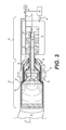
- FIG. 3 is cross-sectional illustration of an exemplary disclosed drive and head that may be used in conjunction with the manufacturing systems of FIGS. 1 and 2 ;
- FIG. 4 is an exploded view illustration of the head of FIG. 3 ;
- FIG. 5 is a perspective illustration of an exemplary disclosed shield that may be connected to the head of FIGS. 3 and 4 ;
- FIGS. 6-9 are diagrammatic illustrations of exemplary disclosed hollow structures that may be manufactured with the system of FIGS. 1 and 2 ;
- FIGS. 10-18 are diagrammatic illustrations of exemplary disclosed weave patterns at may make up walls of the hollow structures of FIGS. 6-9 .
- FIGS. 1 and 2 illustrate different exemplary systems 10 and 12 , which may be used to continuously manufacture hollow composite structures (e.g., tubes, hoses, channels, conduits, ducts, etc.) 14 having any desired cross-sectional shape (e.g., circular or polygonal).
- Each of systems 10 , 12 may include a support 16 , a drive 18 , and a head 20 .
- Head 20 may be coupled to support 16 via drive 18 .
- support 16 is a robotic arm capable of moving drive 18 and head 20 in multiple directions during fabrication of structure 14 , such that a resulting longitudinal axis 22 of structure 14 is three-dimensional.
- FIG. 1 illustrate different exemplary systems 10 and 12 , which may be used to continuously manufacture hollow composite structures (e.g., tubes, hoses, channels, conduits, ducts, etc.) 14 having any desired cross-sectional shape (e.g., circular or polygonal).
- Each of systems 10 , 12 may include a support 16 , a drive 18
- support 16 is an overhead gantry also capable of moving head 20 and drive 18 in multiple directions during fabrication of structures 14 .
- supports 16 of both embodiments are shown as being capable of 6-axis movements, it is contemplated that any other type of support 16 capable of moving drive 18 and head 20 in the same or a different manner could also be utilized, if desired.
- drive 18 in addition to functioning as a mechanical coupling between head 20 and support 16 , may include components that cooperate to also supply power to head 20 .
- These components may include, among other things, a container 24 , one or more actuators disposed inside container 24 , and a plurality of links connecting the various actuators to different portions of head 20 .
- three different actuators 26 , 28 , 30 are shown inside of container 24 as being coupled to head 20 by way of two different shafts 32 , 34 and a rod 36 .
- Actuators 26 and 28 may be rotary-type actuators (e.g., electric, hydraulic, or pneumatic motors), while actuator 30 may be a linear-type actuator (e.g., a solenoid actuator, a hydraulic cylinder, a lead screw, etc.).
- Shaft 32 may be tubular (i.e., cylindrical and hollow) and driven by actuator 26 to rotate about an axis 37 , and shaft 34 may pass through a center of shaft 32 and be driven by actuator 28 to also rotate about axis 37 .
- axis 37 may be considered a non-fiber axis of head 20 .
- shaft 34 is also tubular, and rod 36 may be configured to pass through a center of shaft 34 and be driven by actuator 30 to move axially in-and-out with respect to shaft 34 .
- Rod 36 may also be generally aligned with axis 37 .
- a different number of actuators could be coupled with head 20 by way of a different arrangement of shafts and/or rods, if desired.
- a single actuator could be coupled to rotate both of shafts 32 , 34 (e.g., by way of a gear train—not shown), if desired.
- Electricity may be provided to actuators 30 - 34 from an external supply (e.g., an established utility grid) 38 .
- container 24 may also function as a pressure vessel in some embodiments.
- container 24 may be configured to receive or otherwise contain a pressurized matrix material.
- the matrix material may include any type of liquid resin (e.g., a zero volatile organic compound resin) that is curable.
- Exemplary resins include epoxy resins, polyester resins, cationic epoxies, acrylated epoxies, urethanes, esters, thermoplastics, photopolymers, polyepoxides, and more.
- the pressure of the matrix material inside container 24 may be generated by an external device (e.g., an extruder or another type of pump) 40 that is fluidly connected to container 24 via a corresponding conduit 42 . In another embodiment, however, the pressure may be generated completely inside of container 24 by a similar type of device. In some instances, the matrix material inside container 24 may need to be kept cool and/or dark in order to inhibit premature curing; while in other instances, the matrix material may need to be kept warm for the same reason. In either situation, container 24 may be specially configured (e.g., insulated, chilled, and/or warmed) to provide for these needs.
- an external device e.g., an extruder or another type of pump
- the matrix material stored inside container 24 may be used to coat any number of separate fibers and, together with the fibers, make up a wall of composite structure 14 .
- two separate fiber supplies 44 , 46 are stored within (e.g., on separate internal spools—not shown) or otherwise passed through container 24 (e.g., fed from the same or separate external spools).
- the fibers of supplies 44 , 46 are of the same type and have the same diameter and cross-sectional shape (e.g., circular, square, flat, etc.). In other examples, however, the fibers of supplies 44 , 46 are of a different type, have different diameters, and/or have different cross-sectional shapes.
- Each of supplies 44 , 46 may include a single strand of fiber, a tow or roving of several fiber strands, or a weave of fiber strands.
- the strands may include, for example, carbon fibers, vegetable fibers, wood fibers, mineral fibers, glass fibers, metallic wires, etc.
- the fibers from supplies 44 , 46 may be coated with the matrix material stored in container 24 while the fibers are inside container 24 , while the fibers are being passed to head 20 , and/or while the fibers are discharging from head 20 , as desired.
- the matrix material, the dry fibers from one or both of supplies 44 , 46 , and/or fibers already coated with the matrix material may be transported into head 20 in any manner apparent to one skilled in the art.
- the matrix material is mixed with the fibers from both supplies 44 , 46 , and the matrix-coated fibers are then directed into head 20 via the open interior(s) of shaft(s) 32 and/or 34 .
- dedicated conduits could alternatively be used for this purpose, if desired.
- the matrix material may be pushed through shaft(s) 32 , 34 (and/or the dedicated conduit(s)) by the pressure of container 24 , and the fibers may travel along with the matrix material.
- the fibers (coated or uncoated) may be mechanically pulled through shafts 32 and/or 34 , and the matrix material may be pulled along with the fibers in some embodiments.
- electricity is also supplied to head 20 by way of the empty interior(s) of shaft(s) 32 and/or 34 .
- Head 20 may include a series of cylindrical components nested inside each other that function to create unique weave patterns in the walls of structure 14 out of the matrix-coated fibers received from drive 18 .
- these components may include, among other things, a housing 48 , one or more fiber guides (e.g., a first fiber guide 50 and a second fiber guide 52 ), a diverter 54 , one or more cure enhancers (e.g., a UV light 56 and/or an ultrasonic emitter 58 ), and a cutoff 60 .
- fiber guides e.g., a first fiber guide 50 and a second fiber guide 52
- a diverter 54 e.g., a diverter 54
- cure enhancers e.g., a UV light 56 and/or an ultrasonic emitter 58
- cutoff 60 e.g., matrix-coated fibers from drive 18 may pass through first and/or second fiber guides 50 , 52 , where a rotation in the fibers may be generated.
- the rotating matrix-coated fibers may then pass through an annular gap 61 (shown only in FIG. 3 ) between diverter 54 and housing 48 and around a mouth 62 of diverter 54 , where the resin is caused to cure from the inside-out by way of UV light 56 and/or ultrasonic emitter 58 .
- Housing 48 may be generally tubular, and have an open end 64 (shown only in FIG. 4 ) and an opposing domed end 68 .
- An inner diameter of housing 48 at open end 64 may be larger than outer diameters of fiber guides 50 , 52 , and an internal axial length of housing 48 may be greater than axial lengths of fiber guides 50 , 52 .
- fiber guides 50 , 52 may fit at least partially inside housing 48 .
- both fiber guides 50 , 52 nest completely inside of housing 48 , such that an axial face 69 of housing 48 at open end 64 extends past corresponding ends of fiber guides 50 , 52 .
- Face 69 of housing 48 at open end 64 may be convexly curved to mirror a correspondingly curved outer surface of diverter 54 .
- a center opening 70 may be formed within domed end 68 of housing 48 , allowing shaft 32 , shaft 34 , and rod 36 to pass axially therethrough.
- a seal 72 e.g., an o-ring—shown only in FIG. 3 ) may be disposed at opening 70 and around shaft 32 to inhibit liquid matrix material from leaking out of housing 48 .
- Fiber guides 50 and 52 may also be generally tubular and have an open end 74 and a domed end 76 located opposite open end 74 .
- An inner diameter of fiber guide 50 at open end 74 may be larger than an outer diameter of fiber guide 52 at domed end 76 , and an internal axial length of fiber guide 50 may be greater than an external axial length of fiber guide 52 .
- fiber guide 52 may fit at least partially inside fiber guide 50 .
- fiber guide 52 nests completely inside of fiber guide 50 , such that an end face 78 of fiber guide 50 at open end 74 extends axially past an end face 80 of fiber guide 52 . End faces 78 and 80 of fiber guides 50 , 52 may be convexly curved to mirror the correspondingly curved outer surface of diverter 54 .
- Fiber guides 50 and 52 may each have an annular side wall 82 that extends from open end 74 to domed end 76 .
- a thickness of each side wall 82 may be about the same within engineering tolerances). However, it is contemplated that each side wall 82 could have a different thickness, if desired.
- the thickness of side walls 82 may be sufficient to internally accommodate any number of axially oriented passages 84 . Passages 84 may pass from the corresponding end face (i.e., end face 78 or 80 ) completely through domed end 76 .
- Each passage 84 formed in fiber guide 50 may be configured to receive one or more fibers from one of supplies 44 , 46
- each passage 84 formed in fiber guide 52 may be configured to receive one or more fibers from the other of supplies 44 , 46 . It is contemplated that the same or a different number of passages 84 may be formed within each of fiber guides 50 and 52 , as desired, and/or that passages 84 may have the same or different diameters. In the disclosed embodiment, twenty-four equally spaced passages 84 having substantially identical diameters are formed in each of fiber guides 50 , 52 .
- annular wall 82 of fiber guide 52 may have a smaller diameter than annular wall 82 of fiber guide 50 , the equal spacing between passages 84 within fiber guide 52 may be different than the corresponding equal spacing between passages 84 within fiber guide 50 . It should be noted that passage spacing within one or both of fiber guides 50 , 52 could be unequally distributed in some embodiments. Because fiber guide 52 may nest completely inside fiber guide 50 , the fibers passing through fiber guide 50 may generally be overlapped with the fibers passing through fiber guide 52 during fabrication of structure 14 .
- Each of fiber guides 50 , 52 may be selectively rotated or held stationary during fabrication of structure 14 , such that the fibers passing through each guide together create unique weave patterns (e.g., spiraling patterns, oscillating patterns, straight and parallel patterns, or combination patterns).
- the rotation of fiber guide 50 may be driven via shaft 32
- the rotation of fiber guide 52 may be driven via shaft 34 .
- Shaft 32 may connect to domed end 76 and/or to an internal surface of fiber guide 50 .
- Shaft 34 may pass through a clearance opening 86 in domed end 76 of fiber guide 50 to engage domed end 76 and/or an internal surface of fiber guide 52 .
- the relative rotations of fiber guides 50 , 52 may affect the resulting weave patterns of structure 14 .
- the rotations of fiber guides 50 , 52 may be in the same direction, counter to each other, continuous, intermittent, oscillating, have smaller or larger oscillation ranges, be implemented at lower or higher speeds, etc., in order to produce unique and/or dynamically changing weave patterns having desired properties.
- the rotations of fiber guides 50 , 52 may be choreographed with the movements of support 16 , with the movements of diverter 54 , with an axial extrusion distance and/or rate, and/or with known geometry of structure 14 (e.g., termination points, coupling points, tees, diametrical changes, splices, turns, high-pressure and/or high-temperature areas, etc.).
- diverter 54 is generally bell-shaped and has a domed end 88 located opposite mouth 62 .
- Domed end 88 may have a smaller diameter than mouth 62 and be configured to nest at least partially within fiber guide 52 .
- Mouth 62 may flare radially outward from domed end 88 , and have an outer diameter larger than an outer diameter of fiber guide 52 .
- the outer diameter of mouth 62 may be about the same as an outer diameter of housing 48 .
- Diverter 54 due to its outwardly flaring contour, may function to divert the fibers exiting passages 84 of both fiber guides 50 , 52 radially outward. In this manner, a resulting internal diameter of structure 14 may be dictated by the outer diameter of diverter 54 .
- diverter 54 may divert the fibers against face 69 of housing 48 , thereby sandwiching the fibers within gap 61 (referring to FIG. 3 ). Accordingly, the diverting function of diverter 54 , in addition to establishing the internal diameter of structure 14 , may also dictate the wall thickness of structure 14 . It is contemplated that diverter 54 could have a different shape (e.g., conical, pyramidal, etc.), if desired.
- diverter 54 may be movable to selectively adjust the wall thickness of structure 14 .
- rod 36 may pass through clearance openings 86 of fiber guides 50 , 52 to engage domed end 76 of diverter 54 .
- actuator 30 referring to FIG. 3
- an axial translation of rod 36 caused by actuator 30 may result in a varying width of gap 61 and a corresponding wall thickness of structure 14 .
- thicker walls of structure 14 may be fabricated by pushing diverter 54 away from housing 48 , and thinner walls may be fabricated by pulling diverter 54 closer to housing 48 .
- ridges see FIG. 8
- flanges See FIG. 7
- flexible sections and other features may be created by adjusting the speed and duration of the pulling/pushing motions.
- a fill material e.g., an insulator, a conductor, an optic, a surface finish, etc.
- rod 36 could be hollow (e.g., like shafts 32 , 34 ) and extend through a center of any associated cure enhancer.
- a supply of material e.g., a liquid supply, a foam supply, a solid supply, a gas supply, etc.
- the material would be forced to discharge through rod 36 and into structure 14 .
- rod 36 may extend a distance into structure 14 that corresponds with curing of structure 14 .
- UV light 56 may be configured to continuously expose an internal surface of structure 14 to electromagnetic radiation during the formation of structure 14 .
- the electromagnetic radiation may increase a rate of chemical reaction occurring within the matrix material discharging through gap 61 , thereby helping to decrease a time required for the matrix material to cure.
- UV light 56 may be mounted within mouth 62 of diverter 54 in general alignment with axis 37 , and oriented to direct the radiation away from diverter 54 .
- UV light 56 may include multiple LEDs (e.g., 6 different LEDs) that are equally distributed about axis 37 . However, it is contemplated that any number of LEDs or other electromagnetic radiation sources could alternatively be utilized for the disclosed purposes.
- UV light 56 may be powered via an electrical lead 90 that extends from supply 38 (referring to FIG.
- rod 36 may itself function as electrical lead 90 .
- the amount of electromagnetic radiation may be sufficient to cure the matrix material before structure 14 is axially extruded more than a predetermined length away from mouth 62 . In one embodiment, structure 14 is completely cured before the axial extrusion length becomes equal to an external diameter of structure 14 .
- Ultrasonic emitter 58 may be used in place of or in addition to UV light 56 to increase the cure rate of the matrix material in structure 14 .
- ultrasonic emitter 58 could be mounted directly inside mouth 62 of diverter 54 or alternatively mounted to (e.g., within a corresponding recess of) a distal end of UV light 56 .
- Ultrasonic emitter 58 may be used to discharge ultrasonic energy to molecules in the matrix material, causing the molecules to vibrate. The vibrations may generate bubbles in the matrix material, which cavitate at high temperatures and pressures, which force the matrix material to cure quicker than otherwise possible.
- Ultrasonic emitter 58 may be powered in the same manner as UV light 56 , and also function to cure structure 14 from the inside-out.
- one or more additional cure enhancers could be located to help speed up a cure rate of structure 14 from the outside-in, if desired.
- Cutoff 60 may be used to selectively terminate or otherwise fix a length of structure 14 during manufacturing thereof. As shown in FIGS. 3 and 4 , cutoff 60 may be generally ring-like, and moveably mounted to an external surface of housing 48 . Cutoff 60 may have a sharpened edge 92 that is configured to slide along axis 37 until it engages the matrix-coated fibers discharging through gap 61 . Further sliding in the same direction may then function to shear the fibers against mouth 62 , thereby fixing a length of structure 14 . It should be noted that this shearing action may take place only while the matrix material is still uncured, such that a force required to push edge 92 through the fibers of structure 14 may be lower and a resulting cut surface may have a finer finish.
- the axial movement of cutoff 60 may be generated by a dedicated actuator 93 (see FIG. 3 ).
- Actuator 93 may be mounted to housing 48 and embody a linear actuator (e.g., a hydraulic piston or a solenoid) or a rotary actuator (e.g., a motor that engages external threads on housing 48 ), as desired.
- Actuator 93 may receive electrical power from supply 38 via external wiring.
- the motion of cutoff 60 may be coordinated with the motion of diverter 54 during the fiber shearing of structure 14 .
- diverter 54 may be pulled inward toward housing 48 by rod 36 and actuator 30 .
- a wall thickness of structure 14 may be reduced and thereby made easier to shear.
- a greater clamping force may be exerted on the fibers, thereby reducing the required shearing force and/or movement of cutting edge 92 .
- a shield 94 may be provided and selectively coupled to a distal end of head 20 .
- An exemplary shield 94 is shown in FIG. 5 as including a flexible coupling.
- shield 94 may have a first end 96 having a diameter large enough to internally receive and seal the distal end of head 20 , and a second end 98 having a diameter large enough to internally receive and seal around structure 14 .
- a length of shield 94 may be sufficient to provide a desired curing time for structure 14 , such that the portion of structure 14 engaged by second end 98 is sufficiently cured and will not be deformed by the engagement.
- Shield 94 may provide a more controlled environment for structure 14 , allowing the matrix therein to cure by a desired amount prior to structure 14 being exposed to the inhospitable environment.
- shield 94 may be pressurized with an inert gas, pressurized with a gas that increases a cure rate of the matrix, and/or depressurized to more fully control the environment surrounding structure 14 during manufacture.
- Shield 94 may be flexible, allowing for structure 14 to bend and curve relative to axis 37 (referring to FIG. 3 ) as it is extruded from head 20 .
- System 10 may be capable of producing many different weave patterns within the walls of structure 14 .
- FIGS. 6-9 illustrate exemplary structures 14 that may be possible to manufacture with system 10 .
- FIGS. 10-18 illustrate examples of weave patterns that may be used to make structure 14 .
- FIGS. 6-18 will be discussed in more detail in the following section to further illustrate the disclosed concepts.
- the disclosed systems may be used to continuously manufacture composite structures having any desired cross-sectional shape and length.
- the composite structures may include any number of different fibers of the same or different types and of the same or different diameters.
- the weave patterns used to make the composite structures may be dynamically changed during manufacture of the structures (e.g., without interrupting extrusion of structure 14 ). Operation of system 10 will now be described in detail.
- information regarding a desired hollow structure 14 may be loaded into system 10 (e.g., into a controller responsible for regulating operations of support 16 , actuators 26 - 28 , and/or extruder 40 ).
- This information may include, among other things, a size (e.g., diameter, wall thickness, length, etc.), a contour (e.g., a trajectory of axis 22 ) surface features (e.g., ridge size, location, thickness, length; flange size, location, thickness, length; etc.), connection geometry (e.g., locations and sizes of couplings, tees, splices, etc.), desired weave patterns, and weave transition locations.
- a size e.g., diameter, wall thickness, length, etc.
- a contour e.g., a trajectory of axis 22
- surface features e.g., ridge size, location, thickness, length; flange size, location, thickness, length; etc.
- connection geometry e.g.,
- this information may alternatively or additionally be loaded into system 10 at different times and/or continuously during the manufacturing event, if desired.
- one or more different fibers and/or resins may be selectively installed into system 10 .
- Installation of the fiber(s) may include threading of the fiber(s) through shafts 32 , 34 , through passages 84 in guides 50 , 52 , and through gap 61 .
- the fiber(s) may also need to be connected to a pulling machine (not shown) and/or to a mounting fixture (not shown).
- Installation of the matrix material may include filling of container 24 and/or coupling of extruder 40 to container 24 .
- diverters having larger or smaller diameters, and any number of different configurations of fiber guides may be selectively used with head 20 .
- the component information may then be used to control operation of system 10 .
- the fibers may be pulled and/or pushed along with the matrix material from head 20 at a desired rate at the same time that drive 18 causes fiber guides 50 , 52 to rotate.
- diverter 54 may also be caused to move in or out, and any available cure enhancers (e.g., UV light 56 and/or ultrasonic emitter 58 ) may be activated to cure the matrix material.
- Support 16 may also selectively move head 20 in a desired manner, such that axis 22 of the resulting hollow structure 14 follows a desired trajectory.
- cutoff 60 may be used to sever structure 14 from system 10 in the manner described above.
- FIG. 6 illustrates one example of structure 14 that may be produced by system 10 .
- axis 22 of structure 14 may be translated and/or rotated (e.g., via corresponding movements of head 20 ) in any direction during the lengthwise growth of structure 14 to produce complex geometry.
- the weave pattern of structure 14 may be choreographed with the changing geometry.
- an elbow has been created having multiple weave patterns that transition around a corner section 100 . Specifically, the fibers passing through one of guides 50 or 52 oscillate at opposing ends of corner section 100 , but straighten out (i.e., align with axis 22 ) inside of corner section 100 .
- a frequency of the oscillating fibers may vary.
- the oscillating fibers may oscillate at a slower frequency for a section 102 , and then at a higher frequency for a section 104 . This frequency-changing pattern may be repetitive in some applications.
- the weave pattern used at any particular point along the length of structure 14 may be selected in order to provide desired characteristics at the corresponding point.
- oscillating patterns may be effectively used where slight movement and/or flexing of structure 14 is desired and/or expected over small and large distances.
- One application where oscillating patterns could be helpful may include the manufacture of a gas pipeline over arctic tundra for many continuous miles. In this application, the freezing and thawing of the tundra could cause undesired movements of the pipeline that must be accommodated in order to avoid cracking of the pipeline. The movements may be accommodated via the oscillating weave pattern.
- the oscillating weave pattern may also add toughness and or abrasion resistance to structure 14 .
- the fibers within section 100 may all be parallel in order to produce a different characteristic within structure 14 . For example, parallel fibers may provide for high static strength, where little or no bending is desired or expected.
- FIG. 7 illustrates another example of structure 14 that may be produced by system 10 .
- a coupling 106 is used at a terminal end of structure 14 to connect structure 14 to another device (not shown) or to otherwise close off the end of structure 14 .
- the use of coupling 106 may require different characteristics (e.g., greater strength or stiffness) in the walls of structure 14 and, thus, the weave pattern and/or thickness of structure 14 may change at the coupling location in a corresponding way. For instance, the weave pattern may become denser at this location and/or the wall thickness may increase.
- the weave pattern may become denser by increasing an oscillation frequency for a given axial growth rate (i.e., for a given extrusion rate) and/or by increasing an oscillation range.
- the wall thickness may increase at this location by causing diverter 54 to be pushed further away from housing 48 , such that gap 61 becomes larger.
- FIG. 8 illustrates another example of structure 14 that may be produced by system 10 .
- the geometry of structure 14 changes (e.g., necks down) at a transition location 108 and at a terminal location 110 .
- These geometry changes may involve corresponding changes in the weave pattern and/or in an outer profile of structure 14 .
- the weave pattern at transition location 108 may change from oscillating and parallel fibers to only parallel fibers (or alternatively to only oscillating fibers).
- ridges 112 may be formed at terminal location 110 via the rapid in/out movements of diverter 54 .
- the parallel fibers may enhance a rigidity at transition location 108 , while ridges 112 may facilitate connection with another structure.
- FIG. 9 illustrates a final example of structure 14 that may be produced by system 10 .
- the geometry of structure 14 does not necessarily change.
- changes in the weave pattern of structure 14 may still be varied for application-specific purposes.
- a specific portion 114 of structure 14 may have different characteristics than other portions 116 of the same structure, even though all portions have the same general geometry. For instance, a greater resistance to external temperatures and/or pressures may be required within portion 114 ; a greater abrasion resistance may be required; and/or a greater flexibility and/or rigidity may be required.
- the weave pattern within portion 114 includes parallel fibers on only one section (e.g., one halt) and a density of oscillating fibers on remaining sections that is different than a fiber density within portions 116 .
- FIGS. 10-18 illustrate exemplary weave patterns that may be used at any location on any structure 14 , regardless of structure 14 having changing geometry or characteristic requirements.
- a pattern 118 uses spiraling fibers 120 from guide 50 and spiraling fibers 122 from guide 52 . Spiraling patterns of fibers are known to increase a resistance to internal pressures.
- fibers 120 may be equally interleaved with fibers 122 and may be identical fibers or fibers of different diameters, shapes, and/or sizes, as desired.
- the fibers may transition to a different weave, wherein two of fibers 122 are immediately adjacent each other. This new pattern may be achieved, for example, by increasing a rotational rate of guide 52 to be twice the rotational rate of guide 50 .
- a pattern 124 is created that transitions from both of fibers 120 , 122 spiraling in a first direction to one of fibers 120 , 122 spiraling in a different direction.
- a similar pattern 126 is shown in FIG. 12 , but instead of one of fibers 120 , 122 transitioning to a different direction, both of fibers 120 , 122 transition to the different direction.
- Another similar pattern 128 is shown in FIG. 13 , but instead of only one of fibers 120 , 122 transitioning to spiraling in a different direction, one of fibers 120 , 122 transitions to oscillating rather than spiraling.
- a pattern 130 is created that includes both of fibers 120 and 122 oscillating in a relatively synchronized manner. This synchronicity may involve both fibers 120 , 122 oscillating at about the same frequency, in phase with each other, and through the same ranges.
- FIG. 15 shows a pattern 132 , wherein fibers 120 and 122 are oscillating out of phase with each other using essentially the same frequency and range. However, one of fibers 120 , 122 transitions about half-way along the length of pattern 132 to oscillate at a different frequency and/or through a different range.
- a pattern 134 is shown as having fibers 120 and 122 oscillating out of phase using essentially the same frequency and range. However, one or both of fibers 120 , 122 may shift radial locations about half-way along the length of pattern 134 to move from being overlapping to being adjacent to each other.
- one of fibers 120 , 122 is shown as being straight and generally aligned with axis 22 (referring to FIGS. 1 and 2 ), while the other of fibers 120 , 122 is initially spiraling at an upper-half of pattern 136 . The spiraling fiber 120 or 122 then transitions to oscillating at a lower-half of pattern 136 .
- all of fibers 120 , 122 are straight and aligned with axis 22 , and equally interleaved with each other.
Landscapes
- Engineering & Computer Science (AREA)
- Mechanical Engineering (AREA)
- Chemical & Material Sciences (AREA)
- Composite Materials (AREA)
- Textile Engineering (AREA)
- Physics & Mathematics (AREA)
- Health & Medical Sciences (AREA)
- Thermal Sciences (AREA)
- Oral & Maxillofacial Surgery (AREA)
- Manufacturing & Machinery (AREA)
- Robotics (AREA)
- Electromagnetism (AREA)
- Toxicology (AREA)
- Moulding By Coating Moulds (AREA)
Abstract
Description
Claims (20)
Priority Applications (41)
| Application Number | Priority Date | Filing Date | Title |
|---|---|---|---|
| US15/130,207 US10232551B2 (en) | 2016-04-15 | 2016-04-15 | Head and system for continuously manufacturing composite hollow structure |
| US15/130,412 US10105910B2 (en) | 2016-04-15 | 2016-04-15 | Method for continuously manufacturing composite hollow structure |
| US15/285,165 US9840035B2 (en) | 2016-04-15 | 2016-10-04 | Head and system for continuously manufacturing composite hollow structure |
| US15/295,570 US10335999B2 (en) | 2016-04-15 | 2016-10-17 | Head and system for continuously manufacturing composite hollow structure |
| BR112018071000A BR112018071000A2 (en) | 2016-04-15 | 2017-04-11 | head for a continuous fabrication system, continuous fabrication system and continuous fabrication methods |
| AU2017250100A AU2017250100A1 (en) | 2016-04-15 | 2017-04-11 | Head and system for continuously manufacturing composite hollow structure |
| CA3020925A CA3020925A1 (en) | 2016-04-15 | 2017-04-11 | Head and system for continuously manufacturing composite hollow structure |
| JP2018553461A JP2019513589A (en) | 2016-04-15 | 2017-04-11 | Head and system for continuously producing composite hollow structures |
| KR1020187032922A KR20180134392A (en) | 2016-04-15 | 2017-04-11 | Head and system for continuously manufacturing a composite hollow structure |
| PCT/US2017/026976 WO2017180603A1 (en) | 2016-04-15 | 2017-04-11 | Head and system for continuously manufacturing composite hollow structure |
| RU2018140059A RU2690800C1 (en) | 2016-04-15 | 2017-04-11 | Head and system for continuous production of hollow structure of composite material |
| EP19189070.6A EP3597416A1 (en) | 2016-04-15 | 2017-04-11 | Head and system for continuously manufacturing composite hollow structure |
| CN201780036999.7A CN109562576A (en) | 2016-04-15 | 2017-04-11 | For continuously manufacturing head and the system of composite hollow structure |
| SG11201809039TA SG11201809039TA (en) | 2016-04-15 | 2017-04-11 | Head and system for continuously manufacturing composite hollow structure |
| EP17782963.7A EP3442770A4 (en) | 2016-04-15 | 2017-04-11 | HEAD AND SYSTEM FOR THE CONTINUOUS PRODUCTION OF A HOLLOW COMPOSITE STRUCTURE |
| CA3020434A CA3020434A1 (en) | 2016-04-15 | 2017-04-13 | Head and system for continuously manufacturing composite hollow structure |
| CA3020867A CA3020867C (en) | 2016-04-15 | 2017-04-13 | Head and system for continuously manufacturing composite hollow structure |
| BR112018071068-7A BR112018071068A2 (en) | 2016-04-15 | 2017-04-13 | head for a fabrication system, system for continuous fabrication of a composite structure and method of fabrication of a composite structure |
| EP17783105.4A EP3442767A4 (en) | 2016-04-15 | 2017-04-13 | HEAD AND SYSTEM FOR CONTINUOUSLY FABRICATING A COMPOSITE HOLLOW STRUCTURE |
| JP2018552215A JP2019513583A (en) | 2016-04-15 | 2017-04-13 | Head and system for continuously producing composite hollow structures |
| RU2018139528A RU2686920C1 (en) | 2016-04-15 | 2017-04-13 | Head and system for continuous production of hollow structure from composite material |
| BR112018071073-3A BR112018071073A2 (en) | 2016-04-15 | 2017-04-13 | head for a fabrication system, system for continuously fabricating a composite structure and method for continuously fabricating a composite structure |
| PCT/US2017/027425 WO2017180878A1 (en) | 2016-04-15 | 2017-04-13 | Head and system for continuously manufacturing composite hollow structure |
| CN201780036608.1A CN109562579A (en) | 2016-04-15 | 2017-04-13 | For continuously manufacturing head and the system of composite hollow structure |
| JP2018553075A JP6591696B2 (en) | 2016-04-15 | 2017-04-13 | Head and system for continuous production of composite hollow structures |
| AU2017250655A AU2017250655A1 (en) | 2016-04-15 | 2017-04-13 | Head and system for continuously manufacturing composite hollow structure |
| AU2017250588A AU2017250588B2 (en) | 2016-04-15 | 2017-04-13 | Head and system for continuously manufacturing composite hollow structure |
| SG11201808937SA SG11201808937SA (en) | 2016-04-15 | 2017-04-13 | Head and system for continuously manufacturing composite hollow structure |
| RU2018139735A RU2018139735A (en) | 2016-04-15 | 2017-04-13 | HEAD AND SYSTEM FOR CONTINUOUS PRODUCTION OF COMPOSITE HOUSING STRUCTURE |
| SG11201809037QA SG11201809037QA (en) | 2016-04-15 | 2017-04-13 | Head and system for continuously manufacturing composite hollow structure |
| CN201780037000.0A CN109562580B (en) | 2016-04-15 | 2017-04-13 | Head and system for continuous manufacture of composite hollow structures |
| KR1020187032921A KR20180134988A (en) | 2016-04-15 | 2017-04-13 | Head and system for continuously manufacturing a composite hollow structure |
| KR1020187032923A KR101999082B1 (en) | 2016-04-15 | 2017-04-13 | Head and system for continuously manufacturing a composite hollow structure |
| EP17783135.1A EP3442768A4 (en) | 2016-04-15 | 2017-04-13 | HEAD AND SYSTEM FOR CONTINUOUSLY FABRICATING A COMPOSITE HOLLOW STRUCTURE |
| PCT/US2017/027338 WO2017180826A1 (en) | 2016-04-15 | 2017-04-13 | Head and system for continuously manufacturing composite hollow structure |
| US15/624,243 US10213957B2 (en) | 2016-04-15 | 2017-06-15 | Head and system for continuously manufacturing composite hollow structure |
| US15/722,019 US10668663B2 (en) | 2016-04-15 | 2017-10-02 | Head and system for continuously manufacturing composite hollow structure |
| US15/725,879 US10272615B2 (en) | 2016-04-15 | 2017-10-05 | Head and system for continuously manufacturing composite hollow structure |
| US16/136,613 US10882249B2 (en) | 2016-04-15 | 2018-09-20 | Head and system for continuously manufacturing composite hollow structure |
| US16/455,410 US10981327B2 (en) | 2016-04-15 | 2019-06-27 | Head and system for continuously manufacturing composite tube |
| JP2020036306A JP2020078946A (en) | 2016-04-15 | 2020-03-03 | Head and system for continuously manufacturing composite hollow structure |
Applications Claiming Priority (1)
| Application Number | Priority Date | Filing Date | Title |
|---|---|---|---|
| US15/130,412 US10105910B2 (en) | 2016-04-15 | 2016-04-15 | Method for continuously manufacturing composite hollow structure |
Related Parent Applications (1)
| Application Number | Title | Priority Date | Filing Date |
|---|---|---|---|
| US15/130,207 Continuation-In-Part US10232551B2 (en) | 2016-04-15 | 2016-04-15 | Head and system for continuously manufacturing composite hollow structure |
Related Child Applications (2)
| Application Number | Title | Priority Date | Filing Date |
|---|---|---|---|
| US15/130,207 Continuation-In-Part US10232551B2 (en) | 2016-04-15 | 2016-04-15 | Head and system for continuously manufacturing composite hollow structure |
| US15/295,570 Continuation-In-Part US10335999B2 (en) | 2016-04-15 | 2016-10-17 | Head and system for continuously manufacturing composite hollow structure |
Publications (2)
| Publication Number | Publication Date |
|---|---|
| US20170297053A1 US20170297053A1 (en) | 2017-10-19 |
| US10105910B2 true US10105910B2 (en) | 2018-10-23 |
Family
ID=60040261
Family Applications (1)
| Application Number | Title | Priority Date | Filing Date |
|---|---|---|---|
| US15/130,412 Expired - Fee Related US10105910B2 (en) | 2016-04-15 | 2016-04-15 | Method for continuously manufacturing composite hollow structure |
Country Status (1)
| Country | Link |
|---|---|
| US (1) | US10105910B2 (en) |
Cited By (1)
| Publication number | Priority date | Publication date | Assignee | Title |
|---|---|---|---|---|
| US20210387408A1 (en) * | 2020-06-13 | 2021-12-16 | Xi'an Jiaotong University | Direct inkwriting device and method for a bias-controllable continuous fiber reinforced composite material |
Families Citing this family (3)
| Publication number | Priority date | Publication date | Assignee | Title |
|---|---|---|---|---|
| US11541568B2 (en) * | 2016-01-28 | 2023-01-03 | Hewlett-Packard Development Company, L.P. | Three-dimensional (3D) printing with a detailing agent fluid and a liquid functional material |
| US10589463B2 (en) * | 2017-06-29 | 2020-03-17 | Continuous Composites Inc. | Print head for additive manufacturing system |
| JP7643085B2 (en) * | 2021-02-26 | 2025-03-11 | セイコーエプソン株式会社 | Method for manufacturing three-dimensional object and three-dimensional modeling device |
Citations (98)
| Publication number | Priority date | Publication date | Assignee | Title |
|---|---|---|---|---|
| US2635560A (en) * | 1950-01-19 | 1953-04-21 | Pillsbury Mills Inc | Doughnut cutter |
| US3178328A (en) * | 1961-05-17 | 1965-04-13 | Union Carbide Corp | Process and apparatus for producing plastic net |
| US3183135A (en) * | 1956-08-20 | 1965-05-11 | Nat Standard Co | Method for the manufacture of tires |
| US3286305A (en) | 1964-09-03 | 1966-11-22 | Rexall Drug Chemical | Apparatus for continuous manufacture of hollow articles |
| US3303251A (en) * | 1966-05-13 | 1967-02-07 | Owens Illinois Inc | Method and apparatus for extruding tubing with continuous internal reenforcement members |
| US3331725A (en) * | 1961-08-29 | 1967-07-18 | Plastic Textile Access Ltd | Apparatus for the production of extruded plastic net or net-like products |
| US3384530A (en) * | 1964-07-31 | 1968-05-21 | Plastic Textile Access Ltd | Extruded plastic net, method of making the same and sack made of said net |
| US3393536A (en) * | 1965-06-02 | 1968-07-23 | Daimler Benz Ag | Device for centering two shafts of a flexible coupling |
| US3565985A (en) * | 1969-04-10 | 1971-02-23 | Dow Chemical Co | Method of preparing multilayer plastic articles |
| US3587281A (en) * | 1961-10-02 | 1971-06-28 | Jerome H Lemelson | Extrusion die apparatus |
| US3644696A (en) | 1970-08-28 | 1972-02-22 | Gen Tire & Rubber Co | Means for smoothing the inside surface of plastic hose |
| US3697209A (en) * | 1968-09-20 | 1972-10-10 | Schiesser Ag | Apparatus for manufacturing reinforced tubings from plastic materials |
| US3809514A (en) | 1971-11-13 | 1974-05-07 | Castro Nunez Elem Huecos | Machine for the continuous manufacture of hollow elements |
| US3873024A (en) | 1971-08-13 | 1975-03-25 | Ransburg Corp | Apparatus for spraying a plurality of different powders |
| US3984271A (en) | 1973-06-25 | 1976-10-05 | Owens-Corning Fiberglas Corporation | Method of manufacturing large diameter tubular structures |
| US3993726A (en) | 1974-01-16 | 1976-11-23 | Hercules Incorporated | Methods of making continuous length reinforced plastic articles |
| US4100240A (en) * | 1976-09-30 | 1978-07-11 | Dow Corning Corporation | Liquid polymer extrusion process and product |
| US4344808A (en) | 1975-05-22 | 1982-08-17 | Healey Jr Daniel P | Method for manufacturing synthetic resin laminate tubing having a high bursting strength |
| US4472126A (en) * | 1981-07-17 | 1984-09-18 | Toyoda Gosei Co., Ltd. | Apparatus for manufacturing reinforced hoses |
| US4515737A (en) * | 1980-05-28 | 1985-05-07 | Dainippin Ink and Chemicals Inc. | Process for producing composite plastic pipe |
| US4643940A (en) | 1984-08-06 | 1987-02-17 | The Dow Chemical Company | Low density fiber-reinforced plastic composites |
| US4671761A (en) | 1984-06-30 | 1987-06-09 | Fried. Krupp Gesellschaft Mit Beschrankter Haftung | Apparatus for producing reinforced elongate bodies |
| US4822548A (en) | 1986-06-13 | 1989-04-18 | Firma Carl Freudenberg | Method and apparatus for manufacturing a thread-reinforced rubber hose |
| US4851065A (en) | 1986-01-17 | 1989-07-25 | Tyee Aircraft, Inc. | Construction of hollow, continuously wound filament load-bearing structure |
| US5002712A (en) | 1988-10-19 | 1991-03-26 | Bayer Aktiengesellschaft | Manufacturing composite materials |
| US5037691A (en) | 1986-09-15 | 1991-08-06 | Compositech, Ltd. | Reinforced plastic laminates for use in the production of printed circuit boards and process for making such laminates and resulting products |
| US5041713A (en) | 1988-05-13 | 1991-08-20 | Marinelon, Inc. | Apparatus and method for applying plasma flame sprayed polymers |
| US5069853A (en) * | 1988-06-17 | 1991-12-03 | Gencorp Inc. | Method of configuring extrudate flowing from an extruder die assembly |
| US5128084A (en) | 1990-07-24 | 1992-07-07 | Bridgestone Firestone Inc | Coextrusion apparatus and method for varying the inner profile of a tubular extrudate |
| DE4102257A1 (en) | 1991-01-23 | 1992-07-30 | Artos Med Produkte | Appts. for mfg. reinforced components in laser-cured polymer - has laser-curable polymer in bath, laser directed at polymer surface where fibres pass through polymer and are guided relative to laser beam angle |
| US5139710A (en) * | 1991-05-24 | 1992-08-18 | Global Thermal Conditioning, Inc. | Shadow boundary process for the continuous radiant cure of composites |
| US5226021A (en) * | 1992-09-14 | 1993-07-06 | Dell Olio Matthew P | Train simulation alarm clock apparatus |
| US5286183A (en) * | 1991-05-13 | 1994-02-15 | Pirelli Cavi S.P.A. | Extruder head for applying coatings of polymeric material to semifinished products of elongated cylindrical conformation |
| US5292472A (en) * | 1992-12-18 | 1994-03-08 | Bridgestone Corporation | Coextrusion apparatus and method with rotating cord guidance |
| US5296335A (en) | 1993-02-22 | 1994-03-22 | E-Systems, Inc. | Method for manufacturing fiber-reinforced parts utilizing stereolithography tooling |
| US5340433A (en) | 1989-10-30 | 1994-08-23 | Stratasys, Inc. | Modeling apparatus for three-dimensional objects |
| US5503872A (en) | 1994-03-14 | 1996-04-02 | Mackenzie; Kenneth R. | Flameless plastic coating apparatus and method therefor |
| US5520870A (en) * | 1992-06-08 | 1996-05-28 | British Technology Group Limited | Methods and apparatus for the continuous formation of an extruded product |
| US5746967A (en) | 1995-06-26 | 1998-05-05 | Fox Lite, Inc. | Method of curing thermoset resin with visible light |
| US5866058A (en) | 1997-05-29 | 1999-02-02 | Stratasys Inc. | Method for rapid prototyping of solid models |
| US5879602A (en) * | 1995-06-28 | 1999-03-09 | Werner & Pfleiderer Gmbh | Apparatus and method for impregnating fibrous strands with plastic material |
| US5936861A (en) * | 1997-08-15 | 1999-08-10 | Nanotek Instruments, Inc. | Apparatus and process for producing fiber reinforced composite objects |
| US6042765A (en) | 1993-11-10 | 2000-03-28 | Sekisui Kagaku Kogyo Kabushiki Kaisha | Method for producing a fiber-reinforced thermoplastic resin foamed product |
| US6153034A (en) | 1997-08-03 | 2000-11-28 | Micromod R.P. Ltd | Rapid prototyping |
| US20020009935A1 (en) | 1999-03-23 | 2002-01-24 | Hexcel Corporation | Core-crush resistant fabric and prepreg for fiber reinforced composite sandwich structures |
| US20020062909A1 (en) | 2000-11-29 | 2002-05-30 | Jang Bor Z. | Layer-additive method and apparatus for freeform fabrication of 3-D objects |
| US20020113331A1 (en) | 2000-12-20 | 2002-08-22 | Tan Zhang | Freeform fabrication method using extrusion of non-cross-linking reactive prepolymers |
| US6459069B1 (en) | 1996-11-22 | 2002-10-01 | Joshua E. Rabinovich | Rapid manufacturing system for metal, metal matrix composite materials and ceramics |
| US20020165304A1 (en) | 2000-12-04 | 2002-11-07 | Mulligan Anthony C. | Methods and appratus for preparation of three-dimensional bodies |
| US6501554B1 (en) | 2000-06-20 | 2002-12-31 | Ppt Vision, Inc. | 3D scanner and method for measuring heights and angles of manufactured parts |
| US20030044539A1 (en) | 2001-02-06 | 2003-03-06 | Oswald Robert S. | Process for producing photovoltaic devices |
| US20030056870A1 (en) | 2001-09-21 | 2003-03-27 | Stratasys, Inc. | High-precision modeling filament |
| US6601627B2 (en) | 2000-05-23 | 2003-08-05 | Jamco Corporation | Continuous forming device of fiber reinforced plastic square pipe |
| US20030160970A1 (en) | 2002-01-30 | 2003-08-28 | Anup Basu | Method and apparatus for high resolution 3D scanning |
| US20030186042A1 (en) | 2002-05-07 | 2003-10-02 | Dunlap Earl N. | Process for tempering rapid prototype parts |
| US20030236588A1 (en) | 2002-03-14 | 2003-12-25 | Jang Bor Z. | Nanotube fiber reinforced composite materials and method of producing fiber reinforced composites |
| US20050061422A1 (en) | 2003-09-22 | 2005-03-24 | Martin James P. | Multiple tape laying apparatus and method |
| US20050104257A1 (en) | 2003-09-04 | 2005-05-19 | Peihua Gu | Multisource and multimaterial freeform fabrication |
| US20050109451A1 (en) | 2003-11-20 | 2005-05-26 | Hauber David E. | Composite tape laying apparatus and method |
| US20050230029A1 (en) | 2001-01-02 | 2005-10-20 | Advanced Ceramics Research, Inc. | Continuous fiber reinforced composites and methods, apparatuses, and compositions for making the same |
| US20070003650A1 (en) | 2001-03-01 | 2007-01-04 | Schroeder Ernest C | Apparatus for fabricating fiber reinforced plastic parts |
| US20070228592A1 (en) | 2006-04-03 | 2007-10-04 | Stratasys, Inc. | Auto tip calibration in an extrusion apparatus |
| US20080087371A1 (en) * | 2006-10-11 | 2008-04-17 | Ameron International Corporation | Fiber reinforced resin polymer mortar pole |
| US20080176092A1 (en) | 2001-05-17 | 2008-07-24 | Hexas Llc | Methods and systems for manufacturing a structure having organized areas |
| US20090065971A1 (en) * | 2003-08-29 | 2009-03-12 | Advanced Elastomer Systems, L.P. | Manufacturing of Shaped Coolant Hoses |
| US20090095410A1 (en) | 2007-10-16 | 2009-04-16 | Ingersoll Machine Tools, Inc. | Fiber Placement Machine Platform System Having Interchangeable Head and Creel Assemblies |
| US20090246384A1 (en) | 2008-03-25 | 2009-10-01 | Industrial Technology Research Institute | Apparatuses and methods for coating patterned films using the same |
| US7795349B2 (en) | 1999-11-05 | 2010-09-14 | Z Corporation | Material systems and methods of three-dimensional printing |
| KR100995983B1 (en) | 2008-07-04 | 2010-11-23 | 재단법인서울대학교산학협력재단 | Cross-printing method and apparatus of circuit board |
| US20110032301A1 (en) | 2004-09-21 | 2011-02-10 | Z Corporation | Apparatus and methods for servicing 3d printers |
| US7959983B1 (en) | 2003-10-21 | 2011-06-14 | Farrar Lawrence C | Thermal spray formation of polymer compositions |
| US20110143108A1 (en) | 2008-05-09 | 2011-06-16 | Fit Fruth Innovative Technologien Gmbh | Fibers and methods for use in solid freeform fabrication |
| US20120060468A1 (en) | 2010-09-13 | 2012-03-15 | Experimental Propulsion Lab, Llc | Additive manufactured propulsion system |
| US8221669B2 (en) | 2009-09-30 | 2012-07-17 | Stratasys, Inc. | Method for building three-dimensional models in extrusion-based digital manufacturing systems using ribbon filaments |
| KR101172859B1 (en) | 2010-10-04 | 2012-08-09 | 서울대학교산학협력단 | Ultra precision machining apparatus using nano-scale three dimensional printing and method using the same |
| US20120231225A1 (en) | 2010-09-17 | 2012-09-13 | Stratasys, Inc. | Core-shell consumable materials for use in extrusion-based additive manufacturing systems |
| US20120247655A1 (en) | 2009-11-13 | 2012-10-04 | Karlsruher Institut Fuer Technologie | Method for producing a component from a fiber-reinforced material |
| WO2013017284A2 (en) | 2011-08-04 | 2013-02-07 | Arburg Gmbh + Co. Kg | Method and device for producing a three-dimensional object comprising a fiber feed |
| US20130092316A1 (en) | 2011-10-14 | 2013-04-18 | Rahul Pakal | Reinforced Liners For Pipelines |
| US20130115324A1 (en) * | 2011-11-04 | 2013-05-09 | Ralph Peter Hegler | Apparatus for the Continuous Production of a Twin Wall Pipe with an Integral Socket |
| US20130164498A1 (en) | 2011-12-21 | 2013-06-27 | Adc Acquisition Company | Thermoplastic composite prepreg for automated fiber placement |
| US20130209600A1 (en) | 2012-02-10 | 2013-08-15 | Adam Perry Tow | Multi-axis, multi-purpose robotics automation and quality adaptive additive manufacturing |
| US20130233471A1 (en) | 2012-03-08 | 2013-09-12 | Randall A. Kappesser | Small flat composite placement system |
| US20130337265A1 (en) | 2012-06-19 | 2013-12-19 | EADS UK Limited British | Thermoplastic polymer powder |
| US20140061974A1 (en) | 2012-08-29 | 2014-03-06 | Kenneth Tyler | Method and apparatus for continuous composite three-dimensional printing |
| US20140159284A1 (en) | 2012-12-07 | 2014-06-12 | Stratasys, Inc. | Liquefier assembly for use in additive manufacturing system |
| US20140291886A1 (en) | 2013-03-22 | 2014-10-02 | Gregory Thomas Mark | Three dimensional printing |
| US8956559B2 (en) * | 2009-10-29 | 2015-02-17 | Toyoda Gosei Co., Ltd. | Tubular member extrusion method and tubular member extrusion apparatus |
| US9126367B1 (en) | 2013-03-22 | 2015-09-08 | Markforged, Inc. | Three dimensional printer for fiber reinforced composite filament fabrication |
| US9126365B1 (en) | 2013-03-22 | 2015-09-08 | Markforged, Inc. | Methods for composite filament fabrication in three dimensional printing |
| US9149988B2 (en) | 2013-03-22 | 2015-10-06 | Markforged, Inc. | Three dimensional printing |
| US9156205B2 (en) | 2013-03-22 | 2015-10-13 | Markforged, Inc. | Three dimensional printer with composite filament fabrication |
| US20160031155A1 (en) | 2014-07-29 | 2016-02-04 | Cc3D Llc | Method and Apparatus for Additive Mechanical Growth of Tubular Structures |
| US20160059481A1 (en) | 2014-08-29 | 2016-03-03 | Creopop Pte. Ltd. | Method of 3d printing |
| US20170028644A1 (en) | 2015-07-31 | 2017-02-02 | The Boeing Company | Systems and methods for additively manufacturing composite parts |
| US20170028633A1 (en) | 2015-07-31 | 2017-02-02 | The Boeing Company | Systems and methods for additively manufacturing composite parts |
| US20170028623A1 (en) | 2015-07-31 | 2017-02-02 | The Boeing Company | Systems and methods for additively manufacturing composite parts |
| US20170028635A1 (en) | 2015-07-31 | 2017-02-02 | Boeing Co | Systems and methods for additively manufacturing composite parts |
-
2016
- 2016-04-15 US US15/130,412 patent/US10105910B2/en not_active Expired - Fee Related
Patent Citations (100)
| Publication number | Priority date | Publication date | Assignee | Title |
|---|---|---|---|---|
| US2635560A (en) * | 1950-01-19 | 1953-04-21 | Pillsbury Mills Inc | Doughnut cutter |
| US3183135A (en) * | 1956-08-20 | 1965-05-11 | Nat Standard Co | Method for the manufacture of tires |
| US3178328A (en) * | 1961-05-17 | 1965-04-13 | Union Carbide Corp | Process and apparatus for producing plastic net |
| US3331725A (en) * | 1961-08-29 | 1967-07-18 | Plastic Textile Access Ltd | Apparatus for the production of extruded plastic net or net-like products |
| US3587281A (en) * | 1961-10-02 | 1971-06-28 | Jerome H Lemelson | Extrusion die apparatus |
| US3384530A (en) * | 1964-07-31 | 1968-05-21 | Plastic Textile Access Ltd | Extruded plastic net, method of making the same and sack made of said net |
| US3286305A (en) | 1964-09-03 | 1966-11-22 | Rexall Drug Chemical | Apparatus for continuous manufacture of hollow articles |
| US3393536A (en) * | 1965-06-02 | 1968-07-23 | Daimler Benz Ag | Device for centering two shafts of a flexible coupling |
| US3303251A (en) * | 1966-05-13 | 1967-02-07 | Owens Illinois Inc | Method and apparatus for extruding tubing with continuous internal reenforcement members |
| US3697209A (en) * | 1968-09-20 | 1972-10-10 | Schiesser Ag | Apparatus for manufacturing reinforced tubings from plastic materials |
| US3565985A (en) * | 1969-04-10 | 1971-02-23 | Dow Chemical Co | Method of preparing multilayer plastic articles |
| US3644696A (en) | 1970-08-28 | 1972-02-22 | Gen Tire & Rubber Co | Means for smoothing the inside surface of plastic hose |
| US3873024A (en) | 1971-08-13 | 1975-03-25 | Ransburg Corp | Apparatus for spraying a plurality of different powders |
| US3809514A (en) | 1971-11-13 | 1974-05-07 | Castro Nunez Elem Huecos | Machine for the continuous manufacture of hollow elements |
| US3984271A (en) | 1973-06-25 | 1976-10-05 | Owens-Corning Fiberglas Corporation | Method of manufacturing large diameter tubular structures |
| US3993726A (en) | 1974-01-16 | 1976-11-23 | Hercules Incorporated | Methods of making continuous length reinforced plastic articles |
| US4344808A (en) | 1975-05-22 | 1982-08-17 | Healey Jr Daniel P | Method for manufacturing synthetic resin laminate tubing having a high bursting strength |
| US4100240A (en) * | 1976-09-30 | 1978-07-11 | Dow Corning Corporation | Liquid polymer extrusion process and product |
| US4515737A (en) * | 1980-05-28 | 1985-05-07 | Dainippin Ink and Chemicals Inc. | Process for producing composite plastic pipe |
| US4472126A (en) * | 1981-07-17 | 1984-09-18 | Toyoda Gosei Co., Ltd. | Apparatus for manufacturing reinforced hoses |
| US4671761A (en) | 1984-06-30 | 1987-06-09 | Fried. Krupp Gesellschaft Mit Beschrankter Haftung | Apparatus for producing reinforced elongate bodies |
| US4643940A (en) | 1984-08-06 | 1987-02-17 | The Dow Chemical Company | Low density fiber-reinforced plastic composites |
| US4851065A (en) | 1986-01-17 | 1989-07-25 | Tyee Aircraft, Inc. | Construction of hollow, continuously wound filament load-bearing structure |
| US4822548A (en) | 1986-06-13 | 1989-04-18 | Firma Carl Freudenberg | Method and apparatus for manufacturing a thread-reinforced rubber hose |
| US5037691A (en) | 1986-09-15 | 1991-08-06 | Compositech, Ltd. | Reinforced plastic laminates for use in the production of printed circuit boards and process for making such laminates and resulting products |
| US5041713A (en) | 1988-05-13 | 1991-08-20 | Marinelon, Inc. | Apparatus and method for applying plasma flame sprayed polymers |
| US5069853A (en) * | 1988-06-17 | 1991-12-03 | Gencorp Inc. | Method of configuring extrudate flowing from an extruder die assembly |
| US5002712A (en) | 1988-10-19 | 1991-03-26 | Bayer Aktiengesellschaft | Manufacturing composite materials |
| US5340433A (en) | 1989-10-30 | 1994-08-23 | Stratasys, Inc. | Modeling apparatus for three-dimensional objects |
| US5128084A (en) | 1990-07-24 | 1992-07-07 | Bridgestone Firestone Inc | Coextrusion apparatus and method for varying the inner profile of a tubular extrudate |
| DE4102257A1 (en) | 1991-01-23 | 1992-07-30 | Artos Med Produkte | Appts. for mfg. reinforced components in laser-cured polymer - has laser-curable polymer in bath, laser directed at polymer surface where fibres pass through polymer and are guided relative to laser beam angle |
| US5286183A (en) * | 1991-05-13 | 1994-02-15 | Pirelli Cavi S.P.A. | Extruder head for applying coatings of polymeric material to semifinished products of elongated cylindrical conformation |
| US5139710A (en) * | 1991-05-24 | 1992-08-18 | Global Thermal Conditioning, Inc. | Shadow boundary process for the continuous radiant cure of composites |
| US5520870A (en) * | 1992-06-08 | 1996-05-28 | British Technology Group Limited | Methods and apparatus for the continuous formation of an extruded product |
| US5226021A (en) * | 1992-09-14 | 1993-07-06 | Dell Olio Matthew P | Train simulation alarm clock apparatus |
| US5292472A (en) * | 1992-12-18 | 1994-03-08 | Bridgestone Corporation | Coextrusion apparatus and method with rotating cord guidance |
| US5296335A (en) | 1993-02-22 | 1994-03-22 | E-Systems, Inc. | Method for manufacturing fiber-reinforced parts utilizing stereolithography tooling |
| US6042765A (en) | 1993-11-10 | 2000-03-28 | Sekisui Kagaku Kogyo Kabushiki Kaisha | Method for producing a fiber-reinforced thermoplastic resin foamed product |
| US5503872A (en) | 1994-03-14 | 1996-04-02 | Mackenzie; Kenneth R. | Flameless plastic coating apparatus and method therefor |
| US5746967A (en) | 1995-06-26 | 1998-05-05 | Fox Lite, Inc. | Method of curing thermoset resin with visible light |
| US5879602A (en) * | 1995-06-28 | 1999-03-09 | Werner & Pfleiderer Gmbh | Apparatus and method for impregnating fibrous strands with plastic material |
| US6459069B1 (en) | 1996-11-22 | 2002-10-01 | Joshua E. Rabinovich | Rapid manufacturing system for metal, metal matrix composite materials and ceramics |
| US5866058A (en) | 1997-05-29 | 1999-02-02 | Stratasys Inc. | Method for rapid prototyping of solid models |
| US6153034A (en) | 1997-08-03 | 2000-11-28 | Micromod R.P. Ltd | Rapid prototyping |
| US5936861A (en) * | 1997-08-15 | 1999-08-10 | Nanotek Instruments, Inc. | Apparatus and process for producing fiber reinforced composite objects |
| US20020009935A1 (en) | 1999-03-23 | 2002-01-24 | Hexcel Corporation | Core-crush resistant fabric and prepreg for fiber reinforced composite sandwich structures |
| US7795349B2 (en) | 1999-11-05 | 2010-09-14 | Z Corporation | Material systems and methods of three-dimensional printing |
| US6601627B2 (en) | 2000-05-23 | 2003-08-05 | Jamco Corporation | Continuous forming device of fiber reinforced plastic square pipe |
| US6501554B1 (en) | 2000-06-20 | 2002-12-31 | Ppt Vision, Inc. | 3D scanner and method for measuring heights and angles of manufactured parts |
| US20020062909A1 (en) | 2000-11-29 | 2002-05-30 | Jang Bor Z. | Layer-additive method and apparatus for freeform fabrication of 3-D objects |
| US20020165304A1 (en) | 2000-12-04 | 2002-11-07 | Mulligan Anthony C. | Methods and appratus for preparation of three-dimensional bodies |
| US20020113331A1 (en) | 2000-12-20 | 2002-08-22 | Tan Zhang | Freeform fabrication method using extrusion of non-cross-linking reactive prepolymers |
| US20050230029A1 (en) | 2001-01-02 | 2005-10-20 | Advanced Ceramics Research, Inc. | Continuous fiber reinforced composites and methods, apparatuses, and compositions for making the same |
| US20030044539A1 (en) | 2001-02-06 | 2003-03-06 | Oswald Robert S. | Process for producing photovoltaic devices |
| US20070003650A1 (en) | 2001-03-01 | 2007-01-04 | Schroeder Ernest C | Apparatus for fabricating fiber reinforced plastic parts |
| US20080176092A1 (en) | 2001-05-17 | 2008-07-24 | Hexas Llc | Methods and systems for manufacturing a structure having organized areas |
| US20030056870A1 (en) | 2001-09-21 | 2003-03-27 | Stratasys, Inc. | High-precision modeling filament |
| US20030160970A1 (en) | 2002-01-30 | 2003-08-28 | Anup Basu | Method and apparatus for high resolution 3D scanning |
| US6934600B2 (en) | 2002-03-14 | 2005-08-23 | Auburn University | Nanotube fiber reinforced composite materials and method of producing fiber reinforced composites |
| US20030236588A1 (en) | 2002-03-14 | 2003-12-25 | Jang Bor Z. | Nanotube fiber reinforced composite materials and method of producing fiber reinforced composites |
| US20030186042A1 (en) | 2002-05-07 | 2003-10-02 | Dunlap Earl N. | Process for tempering rapid prototype parts |
| US20090065971A1 (en) * | 2003-08-29 | 2009-03-12 | Advanced Elastomer Systems, L.P. | Manufacturing of Shaped Coolant Hoses |
| US20050104257A1 (en) | 2003-09-04 | 2005-05-19 | Peihua Gu | Multisource and multimaterial freeform fabrication |
| US20050061422A1 (en) | 2003-09-22 | 2005-03-24 | Martin James P. | Multiple tape laying apparatus and method |
| US7959983B1 (en) | 2003-10-21 | 2011-06-14 | Farrar Lawrence C | Thermal spray formation of polymer compositions |
| US20050109451A1 (en) | 2003-11-20 | 2005-05-26 | Hauber David E. | Composite tape laying apparatus and method |
| US20110032301A1 (en) | 2004-09-21 | 2011-02-10 | Z Corporation | Apparatus and methods for servicing 3d printers |
| US20070228592A1 (en) | 2006-04-03 | 2007-10-04 | Stratasys, Inc. | Auto tip calibration in an extrusion apparatus |
| US20080087371A1 (en) * | 2006-10-11 | 2008-04-17 | Ameron International Corporation | Fiber reinforced resin polymer mortar pole |
| US20090095410A1 (en) | 2007-10-16 | 2009-04-16 | Ingersoll Machine Tools, Inc. | Fiber Placement Machine Platform System Having Interchangeable Head and Creel Assemblies |
| US20090246384A1 (en) | 2008-03-25 | 2009-10-01 | Industrial Technology Research Institute | Apparatuses and methods for coating patterned films using the same |
| US20110143108A1 (en) | 2008-05-09 | 2011-06-16 | Fit Fruth Innovative Technologien Gmbh | Fibers and methods for use in solid freeform fabrication |
| KR100995983B1 (en) | 2008-07-04 | 2010-11-23 | 재단법인서울대학교산학협력재단 | Cross-printing method and apparatus of circuit board |
| US8221669B2 (en) | 2009-09-30 | 2012-07-17 | Stratasys, Inc. | Method for building three-dimensional models in extrusion-based digital manufacturing systems using ribbon filaments |
| US8956559B2 (en) * | 2009-10-29 | 2015-02-17 | Toyoda Gosei Co., Ltd. | Tubular member extrusion method and tubular member extrusion apparatus |
| US20120247655A1 (en) | 2009-11-13 | 2012-10-04 | Karlsruher Institut Fuer Technologie | Method for producing a component from a fiber-reinforced material |
| US20120060468A1 (en) | 2010-09-13 | 2012-03-15 | Experimental Propulsion Lab, Llc | Additive manufactured propulsion system |
| US20120231225A1 (en) | 2010-09-17 | 2012-09-13 | Stratasys, Inc. | Core-shell consumable materials for use in extrusion-based additive manufacturing systems |
| KR101172859B1 (en) | 2010-10-04 | 2012-08-09 | 서울대학교산학협력단 | Ultra precision machining apparatus using nano-scale three dimensional printing and method using the same |
| WO2013017284A2 (en) | 2011-08-04 | 2013-02-07 | Arburg Gmbh + Co. Kg | Method and device for producing a three-dimensional object comprising a fiber feed |
| US20130092316A1 (en) | 2011-10-14 | 2013-04-18 | Rahul Pakal | Reinforced Liners For Pipelines |
| EP2589481B1 (en) | 2011-11-04 | 2016-01-20 | Ralph Peter Hegler | Device for continuously manufacturing a composite pipe with connection sleeve |
| US20130115324A1 (en) * | 2011-11-04 | 2013-05-09 | Ralph Peter Hegler | Apparatus for the Continuous Production of a Twin Wall Pipe with an Integral Socket |
| US20130164498A1 (en) | 2011-12-21 | 2013-06-27 | Adc Acquisition Company | Thermoplastic composite prepreg for automated fiber placement |
| US20130209600A1 (en) | 2012-02-10 | 2013-08-15 | Adam Perry Tow | Multi-axis, multi-purpose robotics automation and quality adaptive additive manufacturing |
| US20130233471A1 (en) | 2012-03-08 | 2013-09-12 | Randall A. Kappesser | Small flat composite placement system |
| US20130337265A1 (en) | 2012-06-19 | 2013-12-19 | EADS UK Limited British | Thermoplastic polymer powder |
| US20140061974A1 (en) | 2012-08-29 | 2014-03-06 | Kenneth Tyler | Method and apparatus for continuous composite three-dimensional printing |
| US20140159284A1 (en) | 2012-12-07 | 2014-06-12 | Stratasys, Inc. | Liquefier assembly for use in additive manufacturing system |
| US9126365B1 (en) | 2013-03-22 | 2015-09-08 | Markforged, Inc. | Methods for composite filament fabrication in three dimensional printing |
| US9126367B1 (en) | 2013-03-22 | 2015-09-08 | Markforged, Inc. | Three dimensional printer for fiber reinforced composite filament fabrication |
| US9149988B2 (en) | 2013-03-22 | 2015-10-06 | Markforged, Inc. | Three dimensional printing |
| US9156205B2 (en) | 2013-03-22 | 2015-10-13 | Markforged, Inc. | Three dimensional printer with composite filament fabrication |
| US20140291886A1 (en) | 2013-03-22 | 2014-10-02 | Gregory Thomas Mark | Three dimensional printing |
| US20160031155A1 (en) | 2014-07-29 | 2016-02-04 | Cc3D Llc | Method and Apparatus for Additive Mechanical Growth of Tubular Structures |
| US20160059481A1 (en) | 2014-08-29 | 2016-03-03 | Creopop Pte. Ltd. | Method of 3d printing |
| US20170028644A1 (en) | 2015-07-31 | 2017-02-02 | The Boeing Company | Systems and methods for additively manufacturing composite parts |
| US20170028633A1 (en) | 2015-07-31 | 2017-02-02 | The Boeing Company | Systems and methods for additively manufacturing composite parts |
| US20170028623A1 (en) | 2015-07-31 | 2017-02-02 | The Boeing Company | Systems and methods for additively manufacturing composite parts |
| US20170028635A1 (en) | 2015-07-31 | 2017-02-02 | Boeing Co | Systems and methods for additively manufacturing composite parts |
Non-Patent Citations (18)
| Title |
|---|
| A. Di. Pietro & Paul Compston, Resin Hardness and Interlaminar Shear Strength of a Glass-Fibre/Vinylester Composite Cured with High Intensity Ultraviolet (UV) Light, Journal of Materials Science, vol. 44, Issue 15, pp. 4188-4190 (Aug. 2009). |
| A. Endruweit, M.S. Johnson, & A.C. Long, Curing of Composite Components by Ultraviolet Radiation: A Review, Polymer Composites, vol. 27, Issue 2, pp. 119-128 (Apr. 2006). |
| C. Fragassa, & G. Minak, Standard Characterization for Mechanical Properties of Photopolymer Resins for Rapid Prototyping. 1st Symposium on Multidisciplinary Studies of Design in Mechanical Engineering, Bertinoro, Italy (Jun. 25-28, 2008). |
| English Language Abstract of DE 4102257, published Jul. 30, 1992, obtained from LexisNexis Total Patent. |
| English Language Abstract of KR 100995983, published Nov. 23, 2010, obtained from LexisNexis Total Patent. |
| English Language Abstract of KR 101172859, published Aug. 9, 2012, obtained from LexisNexis Total Patent. |
| Hyouk Ryeol Choi and Se-gon Roh, In-pipe Robot with Active Steering Capability for Moving Inside of Pipelines, Bioinspiration and Robotics: Walking and Climbing Robots, Sep. 2007, p. 544, I-Tech, Vienna, Austria. |
| International Search Report dated Aug. 2, 2017 for PCT/US2017/026976 filed for CC3D LLC on Apr. 11, 2017. |
| International Search Report dated Oct. 13, 2016 for PCT/US2016/042906 to CC3D LLC filed Jul. 19, 2016. |
| Invernizzi et al. UV-Assisted 3D Printing of Glass and Carbon Fiber-Reinforced Dual-Cure Polymer Composites, Materials 2016, 9, 583, dol: 10.3390/ma9070583. |
| Kenneth C. Kennedy II & Robert P. Kusy, UV-Cured Pultrusion Processing of Glass-Reinforced Polymer Composites, Journal of Vinyl and Additive Technology, vol. 1, Issue 3, pp. 182-186 (Sep. 1995). |
| M. Martin-Gallego et al., Epoxy-Graphene UV-Cured Nanocomposites, Polymer, vol. 52, Issue 21, pp. 4664-4669 (Sep. 29, 2011). |
| P. Compston, J. Schiemer, & A. Cvetanovska, Mechanical Properties and Styrene Emission Levels of a UV-Cured Glass-Fibre/Vinylester Composite, Composite Structures, vol. 86, Issues 1-3, pp. 22-26 (Nov. 2008). |
| S. Kumar & J.-P. Kruth, Composites by Rapid Prototyping Technology, Materials and Design, vol. 31, Issue 2, pp. 850-856 (Feb. 2010). |
| S. L. Fan, F. Y. C. Boey, & M. J. M. Abadie, UV Curing of a Liquid Based Bismaleimide-Containing Polymer System, eXPRESS Polymer Letters, vol. 1, No. 6, pp. 397-405 (2007). |
| T. M. Llewelly-Jones, Bruce W. Drinkwater, and Richard S. Trask; 3D Printed Components With Ultrasonically Arranged Microscale Structure, Smart Materials and Structures, 2016, pp. 1-6, vol. 25, IOP Publishing Ltd., UK. |
| Vincent J. Lopata el al., Electron-Beam-Curable Epoxy Resins for the Manufacture of High-Performance Composites, Radiation Physics and Chemistry, vol. 56, Issue 4, pp. 405-415 (Oct. 1999). |
| Yugang Duan et al., Effects of Compaction and UV Exposure on Performance of Acrylate/Glass-Fiber Composites Cured Layer by Layer, Journal of Applied Polymer Science, vol. 123, Issue 6, pp. 3799-3805 (Mar. 15, 2012). |
Cited By (2)
| Publication number | Priority date | Publication date | Assignee | Title |
|---|---|---|---|---|
| US20210387408A1 (en) * | 2020-06-13 | 2021-12-16 | Xi'an Jiaotong University | Direct inkwriting device and method for a bias-controllable continuous fiber reinforced composite material |
| US11679552B2 (en) * | 2020-06-13 | 2023-06-20 | Xi'an Jiaotong University | Direct inkwriting device and method for a bias-controllable continuous fiber reinforced composite material |
Also Published As
| Publication number | Publication date |
|---|---|
| US20170297053A1 (en) | 2017-10-19 |
Similar Documents
| Publication | Publication Date | Title |
|---|---|---|
| US10882249B2 (en) | Head and system for continuously manufacturing composite hollow structure | |
| US10632673B2 (en) | Additive manufacturing system having shutter mechanism | |
| US10105910B2 (en) | Method for continuously manufacturing composite hollow structure | |
| EP3597416A1 (en) | Head and system for continuously manufacturing composite hollow structure | |
| US10759113B2 (en) | Additive manufacturing system having trailing cure mechanism | |
| WO2017180826A1 (en) | Head and system for continuously manufacturing composite hollow structure |
Legal Events
| Date | Code | Title | Description |
|---|---|---|---|
| AS | Assignment |
Owner name: CC3D LLC, IDAHO Free format text: ASSIGNMENT OF ASSIGNORS INTEREST;ASSIGNOR:TYLER, KENNETH LYLE;REEL/FRAME:038295/0687 Effective date: 20160414 |
|
| STCF | Information on status: patent grant |
Free format text: PATENTED CASE |
|
| AS | Assignment |
Owner name: CONTINUOUS COMPOSITES INC., IDAHO Free format text: CHANGE OF NAME;ASSIGNOR:CC3D LLC;REEL/FRAME:049772/0013 Effective date: 20190611 |
|
| FEPP | Fee payment procedure |
Free format text: MAINTENANCE FEE REMINDER MAILED (ORIGINAL EVENT CODE: REM.); ENTITY STATUS OF PATENT OWNER: LARGE ENTITY |
|
| LAPS | Lapse for failure to pay maintenance fees |
Free format text: PATENT EXPIRED FOR FAILURE TO PAY MAINTENANCE FEES (ORIGINAL EVENT CODE: EXP.); ENTITY STATUS OF PATENT OWNER: LARGE ENTITY |
|
| STCH | Information on status: patent discontinuation |
Free format text: PATENT EXPIRED DUE TO NONPAYMENT OF MAINTENANCE FEES UNDER 37 CFR 1.362 |
|
| FP | Lapsed due to failure to pay maintenance fee |
Effective date: 20221023 |