EP2589441B1 - Trägheitsfilter und partikelklassifizierungsvorrichtung - Google Patents
Trägheitsfilter und partikelklassifizierungsvorrichtung Download PDFInfo
- Publication number
- EP2589441B1 EP2589441B1 EP10854049.3A EP10854049A EP2589441B1 EP 2589441 B1 EP2589441 B1 EP 2589441B1 EP 10854049 A EP10854049 A EP 10854049A EP 2589441 B1 EP2589441 B1 EP 2589441B1
- Authority
- EP
- European Patent Office
- Prior art keywords
- inertial filter
- particle
- fluid
- flow
- sheet
- Prior art date
- Legal status (The legal status is an assumption and is not a legal conclusion. Google has not performed a legal analysis and makes no representation as to the accuracy of the status listed.)
- Active
Links
Images





Classifications
-
- B—PERFORMING OPERATIONS; TRANSPORTING
- B01—PHYSICAL OR CHEMICAL PROCESSES OR APPARATUS IN GENERAL
- B01D—SEPARATION
- B01D45/00—Separating dispersed particles from gases or vapours by gravity, inertia, or centrifugal forces
- B01D45/04—Separating dispersed particles from gases or vapours by gravity, inertia, or centrifugal forces by utilising inertia
-
- G—PHYSICS
- G01—MEASURING; TESTING
- G01N—INVESTIGATING OR ANALYSING MATERIALS BY DETERMINING THEIR CHEMICAL OR PHYSICAL PROPERTIES
- G01N1/00—Sampling; Preparing specimens for investigation
- G01N1/02—Devices for withdrawing samples
- G01N1/22—Devices for withdrawing samples in the gaseous state
- G01N1/2202—Devices for withdrawing samples in the gaseous state involving separation of sample components during sampling
- G01N1/2205—Devices for withdrawing samples in the gaseous state involving separation of sample components during sampling with filters
-
- G—PHYSICS
- G01—MEASURING; TESTING
- G01N—INVESTIGATING OR ANALYSING MATERIALS BY DETERMINING THEIR CHEMICAL OR PHYSICAL PROPERTIES
- G01N15/00—Investigating characteristics of particles; Investigating permeability, pore-volume or surface-area of porous materials
- G01N15/02—Investigating particle size or size distribution
- G01N15/0255—Investigating particle size or size distribution with mechanical, e.g. inertial, classification, and investigation of sorted collections
-
- G—PHYSICS
- G01—MEASURING; TESTING
- G01N—INVESTIGATING OR ANALYSING MATERIALS BY DETERMINING THEIR CHEMICAL OR PHYSICAL PROPERTIES
- G01N15/00—Investigating characteristics of particles; Investigating permeability, pore-volume or surface-area of porous materials
- G01N15/02—Investigating particle size or size distribution
- G01N15/0272—Investigating particle size or size distribution with screening; with classification by filtering
Definitions
- the invention relates to an inertial filter placed in a fluid flow path to classify particles contained in fluid by an effect of inertial impaction and others, and a particle classification apparatus equipped with the inertial filter.
- a conventional inertial filter 100 is described below referring to Fig. 16 .
- the conventional inertial filter 100 is placed in a fluid flow path to classify particles.
- the conventional filter 100 has a cylindrical filter body 101, and the filter body 101 has a through cavity 102 having a circular shape in cross section and penetrating through from an upstream side to a downstream side in a fluid passage direction.
- the through cavity 102 includes a diametrically-reduced through cavity 102a provided on the upstream side and having an inner diameter gradually smaller, and a diametrically-constant through cavity 102b continuous to the diametrically-reduced through cavity 102a on the downstream side and having an inner diameter dimensionally fixed.
- the diametrically-constant through cavity 102b is filled with a metal fiber 103 which is an example of incompressible fibers.
- the metal fiber 103 is secured by a mechanism not illustrated in the drawing so that the metal fiber 103 does not fall off from the diametrically-constant through cavity 102b and drop downward in the fluid passage direction.
- an internal pressure of the inertial filter 100 is lowered to or under an external pressure by a suctioning force of a pump not illustrated in the drawing so that a fluid flows in the through cavity 102 from the direction of arrow A to the direction of arrow B by a pressure difference resulting from the internal and external pressures to allow for classification of particles.
- the fluid increases its velocity of fluid flow in the diametrically-reduced through cavity 102a, and the velocity of fluid flow becomes constant once the fluid enters the diametrically-constant through cavity 102b. Then, fine particles contained in the fluid collide with and captured (collected) by the metal fiber 103 in the diametrically-constant through cavity 102b.
- Patent Reference 1 JP Patent Application Publication No. 2008-70222
- US 4,704,527 A describes a device for the separation of airborne particles, such as particles of an aerosol, into grain size classes, comprising an inertial filter with a funnel-shaped nozzle. The shape of which in part determines the velocity of fluid flow.
- US 2003 192363 A1 and US 4,606,232 A disclose an inertial filter for classifying nano-sized particles having a nozzle and a classifying sheet downstream of the nozzle.
- the conventional inertial filter 100 has the following technical problems.
- the first problem is difficulty in achieving aimed initial classifying characteristics because of the lack of uniformity in the spatial density distribution, orientation, and shape of the fiber.
- the second problem is difficulty in filling the diametrically-constant through cavity 102b with the metal fiber 103 at an equal density. As a result of the random density of the metal fiber 103 filling the diametrically-constant through cavity 102b, the classifying characteristics are easily variable, making it difficult to classify particles in a stable manner.
- the third problem is the occurrence of compression of the metal fiber 103 in the fluid passage direction under pressure applied by gas flow during the classifying operation. This adversely affects the classifying characteristics, undermining the stability of the classifying operation.
- the fourth problem is changes possibly occurring during wash of the inertial filter in the spatial density of the metal fiber 103 in the diametrically-constant through cavity 102b because it is difficult to quantity such changes, often compromising reuse of the inertial filter.
- the invention provides an inertial filter wherein an aimed initial classifying performance is easily achievable, and a good collection efficiency is unlikely to deteriorate over a long period of time, thereby enabling to reliably classify particles.
- a particle classification apparatus according to the invention as defined in claim 17 is equipped with an inertial filter filled with an incompressible fiber on an upstream side in a fluid passage direction for removal of coarse particles and the inertial filter recited in 1) on a downstream side in the fluid passage direction for classification of nano-sized particles.
- the fluid is not necessarily limited to gases.
- the fluid includes liquids and materials of other forms.
- the particles captured or collected by the inertial filter are not necessarily limited to particles floating in gases.
- the particles include particles floating in solvents such as a liquids and materials of other forms.
- the particles to be classified are not particularly limited. Examples of the particles to be classified are resin-made fine particles, inorganic fine particles, metallic fine particles, and ceramic fine particles.
- the particles may have any arbitrary shapes.
- the incompressible fiber preferably includes a metal fiber.
- the metal fiber is a stainless fiber, the metal fiber is not necessarily limited to the stainless fiber.
- the metal fiber may be at least a metal fiber selected from aluminum fiber, copper fiber and any other metal fibers. Further, the incompressible fiber may be selected from fibers other than the metal fibers as far as the selected fiber is incompressible and hardly volumetrically changed by fast gas flow passing therethrough.
- the invention can provide an inertial filter achieving advantageous initial classifying characteristics, thereby succeeding in classifying particles in a reliable manner over a long period of time.
- Fig. 1 is a sectional view of the particle classification apparatus.
- a fluid to be classified containing therein floating particles may be gases, liquids, and solvents of other forms.
- the inertial filter 3 for removal of coarse particles has a cylindrical plate 3a.
- the cylindrical plate 3a has a diametrically-reduced through cavity 3b having an inner diameter gradually smaller in the fluid passage direction to expedite a velocity of fluid flow in the fluid passage direction, and a diametrically-constant through cavity 3c continuous to a downstream-side opening of the diametrically-reduced through cavity 3b and having an inner diameter dimensionally fixed in the fluid passage direction to maintain a constant velocity of fluid flow.
- the diametrically-constant through cavity 3c of the inertial filter 3 for removal of coarse particles is filled with an incompressible fiber densely entangled therein, for example, a metal or preferably SUS (stainless steel) fiber 3d which is hardly volumetrically changed by fast gas flow passing therethrough.
- the metal fiber may be at least a metal fiber selected from aluminum fiber, copper fiber, and other metal fibers.
- the fill-in fiber is not necessarily limited to any of these metal fibers as far as the fiber is incompressible and hardly volumetrically changed by fast gas flow passing therethrough.
- the inertial filter 5 for classification of nano-sized particles is continuous to the inertial filter 3 for removal of coarse particles immediately therebelow on the downstream side and coupled with the inertial filter 3 for removal of coarse particles.
- the inertial filter 5 for classification of nano-sized particle has a cylindrical plate 5a located on the upstream side and structurally characterized in that an outer diameter thereof is equal to an outer diameter of the inertial filter 3 for removal of coarse particles and an inner diameter thereof is dimensionally fixed, and a cylindrical plate 5b having an outer diameter equal to the outer diameter of the cylindrical plate 5a and continuous to the cylindrical plate 5a on the downstream side. These plates constitute a filtering space 5c inside.
- the cylindrical plate 5b has a diametrically-reduced through cavity 5d formed at a center position thereof and having an inner diameter gradually smaller from the upstream side to the downstream side in the fluid passage direction.
- a diametrically-constant through cavity 5e having a diametrically fixed inner diameter larger than an inner diameter of a downstream-side opening of the diametrically-reduced through cavity 5d is formed at a lower end of the diametrically-reduced through cavity 5d.
- a particle classifying sheet 9 is provided at the diametrically-constant through cavity 5e.
- the particle classifying sheet 9 has a large number of holes uniformly arranged for classification of nano-sized particles not illustrated in Fig. 1 .
- An example of the particle classifying sheet 9 is a mesh-like sheet.
- the particle classifying sheet 9 has a sheet area larger than a fluid passage area at a site where the sheet is placed, which is the inner diameter of the downstream-side opening of the diametrically-reduced through cavity 5d in the illustrated example.
- a part 9a of the sheet is provided in the form of a partition wall dividing a fluid flow path illustrated with arrow A in two sections in the fluid passage direction for classification of particles.
- the nano-sized particle collector/apparatus introduction unit 7 has a cylindrical plate 7a located on the upstream side and structurally characterized in that an outer diameter thereof is equal to an outer diameter of the inertial filter 5 for classification of nano-sized particles and an inner diameter thereof is dimensionally fixed, and a cylindrical plate 7b having an outer diameter equal to the outer diameter of the cylindrical plate 7a and continuous to the cylindrical plate 7a on the downstream side. These plates constitute a collecting space 7c inside.
- the cylindrical plate 7b has a diametrically-reduced through cavity 7d formed at a center position thereof and having an inner diameter gradually smaller from the upstream side to the downstream side in the fluid passage direction, and a diametrically-constant through cavity 7e continuous to the diametrically-reduced through cavity 7d and having a dimensionally fixed inner diameter, thereby guiding the collected nano-sized particles into the apparatus.
- the apparatus suctions the fluid using a suctioning pump not illustrated in the drawing in the direction illustrated with arrow A to discharge the fluid.
- the particle classification apparatus 1 according to the present preferred embodiment described so far is characterized in that the particle classifying sheet 9 having a large number of minute through holes is used in the inertial filter 5 for classification of nano-sized particles in place of filling the diametrically-constant through cavity with any incompressible fiber as described in the conventional structure.
- the structural characteristics of the particle classifying sheet 9 are described below referring to Figs. 2 to 4B .
- a large number of minute through holes are formed in a mesh-like pattern in the particle classifying sheet 9.
- Examples of the mesh-like sheet are sheets 9a to 9e hereinafter described.
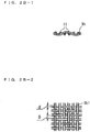
- the sheet 9a has a cross section illustrated in Fig. 2A-1 in side view.
- a fiber 11 made of a plastic or metallic material and having a given wire diameter d is woven with a given aperture D in a plane weave pattern illustrated in Fig. 2A-2 in planar view, so that the sheet 9a has a large number of minute through holes 9a1.
- the sheet 9b has a cross section illustrated in Fig. 2B-1 in side view.
- the fiber is woven in a twill weave pattern illustrated in Figs. 2B-2 in planar view, so that the sheet 9b has a large number of minute through holes 9b1.
- the sheet 9c is obtained by forming a large number of minute through holes 9c1 in a circular shape by etching a conventional sheet as illustrated in Fig. 3A .
- the sheet 9d has a large number of minute through holes 9d1 formed in an oblong shape as illustrated in Fig. 3B .
- the sheet 9e has a large number of minute through holes 9e1 formed in a square shape as illustrated in Fig. 3C .
- the aperture is a largest diameter of a spherical particle that can pass through, and it is an aperture uniformity that plays an important role in achieving a good accuracy of classification.
- the aperture preferably stays in the foregoing numeral ranges to accomplish a better filtering intensity, less pressure loss, and a larger quantity of fluid flow.
- Examples of the mesh-like particle classifying sheet in which plastic fibers are woven are; nylon mesh, polyester mesh, polypropylene mesh, Teflon (registered trademark) mesh, and polyethylene mesh.
- Other examples are fibers in which at least two different fibers are woven such as nylon mesh woven with a carbon fiber.
- the metal-fiber sheet is, for example, a mesh-like filter woven with SUS and others, or a metallic film having a large number of minute through holes formed therein by etching.
- the mesh-like shape is a shape where plural minute through holes for classification are formed in a given area dimension, per unit length, or in a regular pattern.
- the particle classifying sheet 9 has a sheet area larger than the inner diameter of the downstream-side opening of the diametrically-reduced through aperture 5d, and the part 9a of the sheet is provided at the downstream-side opening of the diametrically-reduced through cavity 5d for classification of nano-sized particles.
- Such a simplified structure reduces the likelihood that the following unfavorable events possibly occur near an outer peripheral portion of the particle classifying sheet 9, adversely affect an accuracy of classification in the part 9a; minute through holes randomly arranged by the unraveled meshes, and any gaps between the outer peripheral portion of the particle classifying sheet 9 and the cylindrical plate 5b.
- the diametrically-constant through cavity 3c has a filtering structure where the metal fiber 3d is stacked in layers, to which stokes number Stk and Peclet number Pe usable for selecting a velocity of gas flow and a fiber diameter are applicable.
- the Stokes number Stk is a dimensionless number representing tracking of particles relative to gas flow in filters made of metal fibers, the formula of which is omitted in this description.
- the Stokes number Stk is in proportion to a velocity of fluid flow, a particle density, and the square of a particle diameter but is in reverse proportion to a fiber diameter.
- the diameter of the metal fiber according to the present preferred embodiment is very small, which makes it unnecessary to increase the velocity of fluid flow to as high as an impactor.
- the metal fiber can collect particles not only by particle inertia but also by other mechanisms of collection leveraging blocking, gravity, static electricity, or diffusion.
- the Peclet number Pe is a number representing a ratio of an effect of particle delivery by gas flow and an effect of particle delivery by diffusion, which is in proportion to the velocity of fluid flow and wire diameter but in reverse proportion to a diffusion coefficient. To lessen any influences from diffusion, it is necessary to increase the Peclet number Pe. As particle diameters are smaller, the diffusion coefficient is larger. Because a small value is selected as the fiber diameter, the velocity of fluid flow is preferably higher to improve the selectivity of particle diameters. Based on the description given so far, when the flow of velocity and the fiber diameter are arbitrarily selected (more specifically, at least one of the fiber diameter, aperture, porosity, and pore shapes in the particle classifying sheet is arbitrarily selected), targeted particles can be collected and classified by the metal fiber.
- the quantity of the metal fiber 3d filling the diametrically-constant through cavity 3c of the inertial filter 3 for removal of coarse particles is changed to allow for adjustment of an internal porosity of the diametrically-constant through cavity 3c of the inertial filter 3 for removal of coarse particles, and the wire diameter of the metal fiber 3d is changed so as to minimize any pressure loss without largely undermining the flowability of gas flow in the diametrically-constant through cavity 3c.
- an effect of particle inertia necessary for removal of coarse particles can be obtained even when a small flow quantity is suctioned by a small gas flow suctioning pump.
- the particle classifying sheet 9 of the inertial filter 5 for classification of nano-sized particles can classify nano-sized particles.
- the particle classifying sheet 9 formed in the mesh-like shape is not compressed in the fluid passage direction under an action of fluid pressure, and the mesh-like shape can equalize the porosity and pore shapes.
- the fluid flowability in the particle classifying sheet 9 is hardly undermined.
- a small quantity is suctioned by a small suctioning pump, therefore, an effect of particle inertia necessary for classification of nano-sized particles can be obtained with any pressure loss being minimized.
- the cylindrical plate 5b of the inertial filter 5 for classification of nano-sized particles illustrated in Fig. 1 is replaceable with flow quantity adjusting nozzles 13a to 13c as illustrated in Figs. 5 a1), b1), and c1) to allow for adjustment of the quantity of flow.
- flow quantity adjusting nozzles 13a to 13c On lower-end opening sides of the flow quantity adjusting nozzle 13a to 13c are provided particle classifying sheets 15a to 15c, and O rings 17a to 17c are fitted in outer peripheries of the particle classifying sheets 15a to 15c so that respective fluid flow paths illustrated with arrows in the drawings are sealed from outside.
- a diametrically-reduced through cavity 13a1 is diametrically reduced by a conventional diameter reducing ratio per unit length in the fluid passage direction, and the fluid flows therethrough at a standard velocity of fluid flow.
- a lateral axis represents a particle diameter
- a vertical axis represents a collection efficiency
- a diametrically-reduced through cavity 13b1 of the flow quantity adjusting nozzle 13b is diametrically reduced by a large diameter reducing ratio, and the velocity of fluid flow is thereby increased. Therefore, the collecting characteristics shift from the characteristics c1 to characteristics c2 as illustrated in Fig. 5 b2), resulting in a smaller 50% cut-off (classification) diameter.
- a diametrically-reduced through cavity 13c1 of the flow quantity adjusting nozzle 13c is diametrically reduced by a small diameter reducing ratio, and the velocity of fluid flow is reduced. Therefore, the collecting characteristics shift from the characteristics c1 to characteristics c3 as illustrated in Fig. 5 c2), increasing the classification diameter.
- the flow quantity adjusting nozzle is replaced with the flow quantity adjusting nozzles 13a to 13c to change the classification diameter through stages, so that a particle distribution is obtained.
- the classification diameter is fixed as far as the velocity of fluid flow is set to a constant velocity. This is particularly advantageous for specific fields of application where the classification diameter should be fixed, such as environmental measurements.
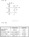
- FIG. 6A-1 The flow quantity adjustment by the flow quantity adjusting nozzle is described referring to Figs. 6A-1 to 6A-3 .
- An inertial filter 25a illustrated in Fig. 6A-1 has a flow quantity adjusting nozzle 19a, a particle classifying sheet 21a, and an O ring 23a.
- Fig. 6A-2 is a top view of the flow quantity adjusting nozzle 19a, while Fig. 6A-3 is a back view of the flow quantity adjusting nozzle 19a.
- An inertial filter 25b illustrated in Fig. 6B -1 has a flow quantity adjusting nozzle 19b, a particle classifying sheet 21b, and an O ring 23b.
- Fig. 6B-2 is a top view of the flow quantity adjusting nozzle 19b, while Fig. 6B-3 is a back view of the flow quantity adjusting nozzle 19b.
- the arrows illustrated in the drawings denote the fluid passage direction.
- the flow quantity adjusting nozzle 19a has a diametrically-reduced through cavity 27a.
- the flow quantity adjusting nozzle 19b of the inertial filter 25b illustrated in Fig. 6B-1 has a plurality of diametrically-reduced through cavities 27b, wherein the classifying characteristics are stabilized, and the quantity of fluid flow can be increased.
- a particle classification apparatus 29 includes an inertial filter 31 for removal of coarse particles, an inertial filter 33 for classification of nano-sized particles, and a particle collector/apparatus introduction unit 35.
- the apparatus further includes a particle classifying sheet 37 provided in the inertial filter 33 for classification of nano-sized particles, wherein a plurality of particle classifying sheets 37a to 37c constitute the particle classifying sheet 37.
- the classification diameter is smaller as the number of layers is larger as illustrated in classifying characteristics of Fig.
- a reference numeral 39 is a flow quantity adjusting nozzle of the inertial filter 33 for classification of nano-sized particles.
- the particle classifying sheet 37 illustrated in Fig. 7 includes three sheets for illustrative convenience, however, the number of the sheets is not necessarily limited to three.
- Fig. 9A illustrates an inertial filter 41 for classification of nano-sized particles
- Fig. 9B is an exploded view of the filter.
- the inertial filter 41 for classification of nano-sized particles includes a replaceable flow quantity adjusting nozzle 45 in a filter case 43, and a plurality of replaceable particle classifying sheets 47a to 47c and a plurality of replaceable intermediary spacers 49a to 49c.
- the particle classifying sheets 47a to 47c each has a given sheet thickness dimension and a circular sheet area larger than a circular area dimension of a downstream-side opening of the flow quantity adjusting nozzle 45. These sheets are partly facing the downstream-side opening of the flow quantity adjusting nozzle 4.
- the intermediary spacers 49a to 49c are stacked in layers alternating with the particle classifying sheets 47a to 47c and have a circular shape and an area dimension equal to those of the particle classifying sheets 47a to 47c.
- the intermediary spacers 49a to 49c have an equal spacer thickness dimension and have through holes 50a to 50c diametrically equal to the downstream-side opening of the flow quantity adjusting nozzle 45.
- the through holes 50a to 50c combined by the layered structure of the intermediary spacers 49a to 49c form a through hole where the velocity of fluid flow becomes constant.
- the parts constituting the filter are replaceable and differently combined.
- the different combinations of these parts facilitate control of the velocity of fluid flow and particle classification.
- Fig. 10 illustrates an inertial filter 51 having three particle classifying sheets 47a to 47c and three intermediary spacers 49a to 49c.
- Fig. 10 a2) illustrates classifying characteristics c4 of the filter.
- Fig. 10 b1) illustrates an inertial filter 53 having five particle classifying sheets 47a to 47e and four intermediary spacers 49a to 49d.
- Fig. 10 b2) illustrates classifying characteristics c5 of the filter.
- Fig. 10 a1) illustrates an inertial filter 51 having three particle classifying sheets 47a to 47c and three intermediary spacers 49a to 49c.
- Fig. 10 a2) illustrates classifying characteristics c4 of the filter.
- Fig. 10 b1) illustrates an inertial filter 53 having five particle classifying sheets 47a to 47e and four intermediary spacers 49a to 49d.
- Fig. 10 b2) illustrates classifying characteristics c5 of the filter.
- Fig. 10 a1) illustrates
- FIG. 10 c1) illustrates an inertial filter 55 having two particle classifying sheets 47a and 47b and two intermediary spacers 49a and 49b.
- Fig. 10 c2) illustrates classifying characteristics c6 of the filter.
- Fig. 10 d) illustrates classification diameter characteristics, where a lateral axis represents the number of particle classifying sheets and a vertical axis represents the classification diameter. It is known from the illustration of Fig. 10 d) that the classification diameter is smaller as the number of the particle classifying sheets is larger.
- Fig. 11 a1) illustrates an inertial filter 57 having a flow quantity adjusting nozzle 45a which applies a standard velocity of fluid flow, particle classifying sheets 47a to 47c, and intermediary spacers 48a1 to 48a3.
- Fig. 11 a2) illustrates classifying characteristics c7 of the inertial filter 57.
- the classifying characteristics c7 are accomplished by a diameter reducing ratio of a diametrically-reduced through cavity 51a of the flow quantity adjusting nozzle 45a per unit length in the fluid passage direction and the intermediary spacers 48a1 to 48a3.
- FIG. 11 b1) illustrates an inertial filter 59 having a flow quantity adjusting nozzle 45b which applies a velocity of fluid flow higher than the standard velocity of fluid flow, particle classifying sheets 47a to 47c, and intermediary spacers 48b1 to 48b3.
- Fig. 11 b2) illustrates classifying characteristics c8 of the inertial filter 59.
- a diametrically-reduced through cavity 51b of the flow quantity adjusting nozzle 45b has a large diameter reducing ratio, and the intermediary spacers 48b1 to 48b3 have small through holes.
- the velocity of fluid flow is higher than the standard velocity of fluid flow, resulting in a larger effect of inertial impaction of nano-sized particles in the fluid.
- the classifying characteristics shift from the characteristics c7 to the characteristics c8, enabling to collect nano-sized particles having smaller particle sizes.
- Fig. 11 c1) illustrates an inertial filter 61 having a flow quantity adjusting nozzle 45c which applies a velocity of fluid flow higher than the standard velocity of fluid flow, particle classifying sheets 47a to 47c, and intermediary spacers 48c1 to 48c3.
- Fig. 11 c2) illustrates classifying characteristics c9 of the inertial filter 61.
- a diametrically-reduced through cavity 51c of the flow quantity adjusting nozzle 45b has a small diameter reducing ratio, and the intermediary spacers 48c1 to 48c3 have large through holes. Therefore, the velocity of fluid flow is lower than the standard velocity of fluid flow, resulting in a smaller effect of inertial impaction of nano-sized particles in the fluid. As a result, the classifying characteristics shift from the characteristics c7 to the characteristics c9.
- the classification diameter can be controlled by differently combining the flow quantity adjusting nozzles 45a to 45c, and intermediary spacers 48a1 to 48a3, 48b1 to 48b3, and 48c1 to 48c3.
- Fig. 12 a1) illustrates an inertial filter 63 having intermediary spacers 49a1 to 49c1 which apply a standard porosity.
- Fig. 12 a2) illustrates classifying characteristics c9 of the inertial filter 63.
- the porosity of the inertial filter 63 is used as a standard porosity, spacer thicknesses of the intermediary spacers 49a1 to 49c1 in the inertial filter 63 are respectively t, and a diametrically-constant through passage formed by the intermediary spacers 49a1 to 49c1 has a length of 3t in total.
- Reference numerals 47a to 47c are particle classifying sheets.
- Fig. 12 b1) illustrates an inertial filter 65 having intermediary spacers 49a2 to 49c2.
- Fig. 12 b2) illustrates classifying characteristics c10 of the inertial filter 65.
- spacer thicknesses of the intermediary spacers 49a2 to 49c2 are respectively, for example, 2t, and a diametrically-constant through passage formed by the intermediary spacers 49a2 to 49c2 has a length of 6t in total. This increases the porosity (filling ratio is smaller), enabling to collect nano-sized particles having smaller particle sizes.
- Fig. 12 c1) illustrates an inertial filter 67 having intermediary spacers 49a3 to 49c3.
- Fig. 12 c2) illustrates classifying characteristics c11 of the inertial filter 67.
- spacer thicknesses of the intermediary spacers 49a3 to 49c3 are respectively, for example, 0.5t, and a diametrically-constant through passage formed by the intermediary spacers 49a3 to 49c3 has a length of 1.5t in total as compared to the inertial filter 63. This decreases the porosity (filling ratio is larger).
- the classification diameter is controllable as illustrated in Figs. 12 a2), b2), and c2) by differently combining the intermediary spacers.
- FIG. 13A-1 to 13B-3 is described an example in which the quantity of fluid flow is adjusted by a flow quantity adjusting nozzle and intermediary spacers.
- An inertial filter 69 illustrated in Fig. 13A-1 has a flow quantity adjusting nozzle 50a, particle classifying sheets 52a to 52c, and intermediary spacers 54a1 to 54c1.
- Fig. 13A-2 illustrates a top view and a back view of the flow quantity adjusting nozzle 50a
- Fig. 13A-3 illustrates a top view of the intermediary spacers 54a1 to 54c1.
- the flow quantity adjusting nozzle 50a, particle classifying sheets 52a to 52c, and intermediary spacers 54a1 to 54c1 have an equal outer dimension in a plane orthogonal to the fluid passage direction.
- the particle classifying sheets 52a to 52c are stacked in layers being alternately interposed between the flow quantity adjusting nozzle 50a and the intermediary spacers 54a1 to 54c1.
- the intermediary spacers 54a1 to 54c1 each has a through hole, and these through holes 70a to 70c are diametrically equal to a downstream-side opening of a diametrically-reduced through cavity 70 of the flow quantity adjusting nozzle 50a.
- the through holes 70a to 70c overlap with one another at a position in a fluid passage direction A0.
- An inertial filter 71 illustrated in Fig. 13B-1 has a flow quantity adjusting nozzle 50b, particle classifying sheets 52a to 52c, and intermediary spacers 54a2 to 54c2.
- Fig. 13B-2 illustrates a top view and a back view of the flow quantity adjusting nozzle 50b
- Fig. 13B-3 illustrates a top view of the intermediary spacers 54a2 to 54c2.
- the flow quantity adjusting nozzle 5b, particle classifying sheets 52a to 52c, and intermediary spacers 54a2 to 54c2 have an equal outer dimension in a plane orthogonal to the fluid passage direction.
- the particle classifying sheets 52a to 52c are stacked in layers being alternately interposed between the flow quantity adjusting nozzle 50b and the intermediary spacers 54a2 to 54c2.
- the flow quantity adjusting nozzle 50b has a plurality of the diametrically-reduced through cavities 70 formed therein.
- the intermediary spacers 54a2 to 54c2 have a plurality of through holes 70a to 70c corresponding to and diametrically equal to downstream-side openings of a plurality of through cavities 70' of the flow quantity adjusting nozzle 50b.
- the plurality of through holes 70a to 70c overlap with one another at a position in each of fluid passage directions A1 to A3.
- the inertial filter 69 illustrated in Fig. 13A-1 and the inertial filter 71 illustrated in Fig. 13B-1 respectively have different numbers of through passages in the fluid passage direction.
- the velocity of fluid flow of the inertial filter 69 illustrated in Fig. 13A-1 in the fluid passage direction A0 and the velocity of fluid flow of the inertial filter 71 illustrated in Fig. 13B-1 in the fluid passage directions A1 to A3 can be arranged to be constant and equal, or the inertial filter 69 can be arranged to have a larger quantity of flow than the inertial filter 71.
- Fig. 14 illustrates classifying characteristics of the inertial filter, where a lateral axis represents an aerodynamic diameter and a vertical axis represents a collection efficiency.
- a reference symbol c12 is classifying characteristics based on theoretical values.
- black squares ⁇ and black triangles ⁇ show classifying characteristics of first and second inertial filters having five particle classifying sheets and five intermediary spacers, and ⁇ shows classifying characteristics of a third inertial filter having five particle classifying sheets and 20 intermediary spacers.
- the inertial filter according to the present preferred embodiment has favorable classifying characteristics where theoretical values and experimental value are substantially equal.
- Fig. 15 illustrates an inertial filter as a final product.
- the inertial filter includes a pair of cylindrical male and female connectors 80 and 81, wherein a protruding edge portion 80a of the male connector 80 is fitted in a dented portion 81a of the female connector 81 to form a fluid flow path in a direction illustrated with arrows.
- a nut 82 is screwed into a spiral groove 81 on an outer periphery of the female connector 81 from the side of the male connector 80 so that the connectors 80 and 81 are fastened to each other with the nut 82.
- a through cavity 80b diametrically smaller in the arrow direction, and a plurality of particle classifying sheets 80c and intermediary spacers 80d are provided in the protruding edge portion 80a of the male connector 80.
- the inertial filter according to the present preferred embodiment is equipped with a particle classifying sheet having a plurality of particle classifying holes uniformly arranged, wherein the particle classifying sheet has an area larger than a fluid passage area at a site where the sheet is placed, and a part of the sheet is provided in the form of a partition wall dividing a fluid flow path in two sections in a fluid passage direction. Therefore, aimed initial classifying characteristics are easily obtainable, and the classifying characteristics are stabilized over a long period of time unlike any conventional inertial filter having a diametrically-constant through cavity filled with fiber.
- Such a conventional inertial filter having a diametrically-constant through cavity filled with fiber had the problems; initial classifying characteristics are difficult to control because of the lack of uniformity in a filling density, orientation, and pore shapes of the fiber, and the stability of the classifying operation is undermined by compression of the fiber in the fluid passage direction under pressure applied from gas flow during the classifying operation.
- the inertial filter according to the present preferred embodiment can solve these technical problems. Further, the inertial filter according to the present preferred embodiment, wherein the sheet is used in place of the fiber, is more easily washable, which facilitates reuse of the inertial filter.
- the invention provides an advantageous inertial filter wherein aimed initial classifying characteristics are easily achievable, and a good collection efficiency is unlikely to deteriorate over a long period of time, enabling to reliably classify particles.
- the invention is applicable to an inertial filter placed in a fluid flow path to classify particles of fluid by an effect of inertial impaction, and a particle classification apparatus equipped with the inertial filter.
Landscapes
- Chemical & Material Sciences (AREA)
- Health & Medical Sciences (AREA)
- Life Sciences & Earth Sciences (AREA)
- General Physics & Mathematics (AREA)
- Pathology (AREA)
- Analytical Chemistry (AREA)
- Biochemistry (AREA)
- General Health & Medical Sciences (AREA)
- Physics & Mathematics (AREA)
- Immunology (AREA)
- Dispersion Chemistry (AREA)
- Chemical Kinetics & Catalysis (AREA)
- Engineering & Computer Science (AREA)
- Biomedical Technology (AREA)
- Molecular Biology (AREA)
- Separation Of Solids By Using Liquids Or Pneumatic Power (AREA)
- Sampling And Sample Adjustment (AREA)
- Combined Means For Separation Of Solids (AREA)
Claims (18)
- Trägheitsfilter (5)
angeordnet in einem Fluidströmungspfad zum Durchleiten eines Fluids, das nanogroße Partikel enthält, um die nanogroßen Partikel im Fluidströmungspfad durch einen Effekt der Partikelträgheit zu sammeln, wobei der Ansaugfilter die nanogroßen Partikel mit kleineren Partikelgrößen sammelt, wenn die Strömungsgeschwindigkeit des Fluids erhöht wird, wobei der Ansaugfilter Folgendes beinhaltet:
eine Durchflussmengeneinstelldüse (5b)
die auf einer stromaufwärts gelegenen Seite des Fluidströmungspfades angeordnet ist und einen diametral reduzierten Hohlraum aufweist, der in Fluiddurchgangsrichtung diametral kleiner ist, wobei die Durchflussmengeneinstelldüse die Geschwindigkeit des Fluidstroms in Abhängigkeit von einem unterschiedlichen Durchmesser-Reduktionsverhältnis des diametral reduzierten Hohlraums anpasst; und
ein Partikelklassifizierungsblech (9),
das weiter entfernt auf einer stromabwärts gelegenen Seite des Fluidströmungspfades angeordnet ist als die Durchflussmengeneinstelldüse und mehrere gleichmäßig angeordnete Partikelklassifizierungsöffnungen aufweist, wobei die mehreren Partikelklassifizierungsöffnungen gebildet werden, um die nanogroßen Partikel durch einen Effekt der Partikelträgheit zu sammeln, wobei das Partikelklassifizierungsblech einen Blechbereich aufweist, der größer ist als eine stromabwärtsseitige Öffnung des diametral reduzierten Hohlraums und in Form einer Trennwand (9a) bereitgestellt wird,
die den Fluidströmungspfad in zwei Abschnitte in Fluiddurchgangsrichtung teilt, um die stromabwärtsseitige Öffnung zu blockieren - Trägheitsfilter nach Anspruch 1, wobei
ein Blech das Partikelklassifizierungsblech in Fluiddurchgangsrichtung darstellt. - Trägheitsfilter nach Anspruch 1, wobei
mehrere laminierte Bleche das Partikelklassifizierungsblech in Fluiddurchgangsrichtung darstellen. - Trägheitsfilter nach Anspruch 1, wobei
das Partikelklassifizierungsblech ein Blech mit einer großen Anzahl von Durchgangsöffnungen ist, die in einem maschenartigen Muster als mehrere der Partikelklassifizierungslöcher gebildet sind. - Trägheitsfilter nach Anspruch 4, wobei
das Partikelklassifizierungsblech ein maschenartiges Blech mit einem Drahtdurchmesser im Bereich von 5 bis 20 µm und einer Öffnung im Bereich von 40 bis 300 µm ist. - Trägheitsfilter nach Anspruch 1, wobei
die Durchflussmengeneinstelldüse so vorgesehen ist, dass die Durchflussmengeneinstelldüse durch eine andere Durchflussmengeneinstelldüse austauschbar ist, die einen diametral reduzierten Hohlraum mit einem unterschiedlichen Reduzierverhältnis des Durchmessers aufweist, um eine Anpassung der Strömungsgeschwindigkeit des Fluides zu ermöglichen. - Trägheitsfilter nach Anspruch 1, wobei
das Partikelklassifizierungsblech so vorgesehen ist, dass das Partikelklassifizierungsblech durch ein anderes Partikelklassifizierungsblech ersetzt werden kann, in dem mindestens ein Faserdurchmesser, eine Öffnung, eine Porosität oder eine Porenform davon verschieden ist. - Trägheitsfilter nach Anspruch 1, wobei
ein Zwischenabstandhalter zwischen mehreren der Partikelklassifizierungsbleche in Fluiddurchgangsrichtung angeordnet ist, und der Zwischenabstandhalter so vorgesehen ist, dass der Zwischenabstandhalter durch einen anderen Zwischenabstandhalter, der eine diametral davon verschiedene Durchgangsöffnung aufweist, austauschbar ist. - Trägheitsfilter nach Anspruch 1, wobei
mehrere der Partikelklassifizierungsbleche übereinander gestapelt sind, wobei dazwischen ein Zwischenabstandshalter angeordnet ist - Trägheitsfilter nach Anspruch 9, wobei
das Partikelklassifizierungsblech durch ein anderes Partikelklassifizierungsblech austauschbar ist, in dem mindestens ein Faserdurchmesser, eine Öffnung, eine Porosität oder eine Porenform unterschiedlich ist, um eine Steuerung der Partikelklassifizierung zu ermöglichen. - Trägheitsfilter nach Anspruch 10, wobei
die Partikelklassifizierung steuerbar ist durch Änderung der Anzahl der in Schichten gestapelten Partikelklassifizierungsbleche. - Trägheitsfilter nach Anspruch 9, wobei
die Partikelklassifizierung steuerbar ist durch Änderung der Anzahl der in Schichten gestapelten Zwischenabstandhalter - Trägheitsfilter nach Anspruch 9, wobei
die Durchflussmengeneinstelldüse austauschbar gegen eine andere Durchflussmengeneinstelldüse ist, die einen anderen Strömungspfad aufweist, um eine Einstellung der Strömungsgeschwindigkeit des Fluids zu ermöglichen. - Trägheitsfilter nach Anspruch 9, wobei
der Zwischenabstandhalter austauschbar ist gegen einen anderen Zwischenabstandhalter mit einer Durchgangsöffnung, die sich diametral unterscheidet, um eine Einstellung der Strömungsgeschwindigkeit des Fluids zu ermöglichen. - Trägheitsfilter nach Anspruch 10, wobei
die Partikelklassifizierung durch Ändern einer Abstandsdickenabmessung des Zwischenabstandshalters steuerbar ist. - Trägheitsfilter nach Anspruch 10, wobei
die Anzahl der Strömungspfade der Durchflussmengeneinstelldüse und die Anzahl der Durchgangsöffnungen des Zwischenabstandhalters, die der Anzahl der Strömungspfade entsprechen, geändert werden, um eine Anpassung der Durchflussmenge zu ermöglichen. - Trägheitsfilter, nach einem der Ansprüche 1 bis 16, wobei
die Durchflussmengeneinstelldüse gegen eine andere Durchflussmengeneinstelldüse austauschbar ist, die eine andere Anzahl der diametral reduzierten Hohlräume aufweist, um die Einstellung einer Durchflussmenge des Fluids zu ermöglichen. - Partikelklassifizierungsvorrichtung, die mit einem Trägheitsfilter ausgestattet ist, der mit einer nicht komprimierbaren Faser auf einer stromaufwärts gelegenen Seite in Fluiddurchgangsrichtung gefüllt ist, zur Entfernung von Grobpartikeln und dem Trägheitsfilter nach Anspruch 1 auf einer stromabwärts gelegenen Seite in der Fluiddurchgangsrichtung zur Klassifizierung von nanogroßen Partikeln.
Applications Claiming Priority (2)
| Application Number | Priority Date | Filing Date | Title |
|---|---|---|---|
| JP2010148870A JP4714915B1 (ja) | 2010-06-30 | 2010-06-30 | 慣性フィルタおよび粒子分級装置 |
| PCT/JP2010/006458 WO2012001752A1 (ja) | 2010-06-30 | 2010-11-02 | 慣性フィルタおよび粒子分級装置 |
Publications (3)
| Publication Number | Publication Date |
|---|---|
| EP2589441A1 EP2589441A1 (de) | 2013-05-08 |
| EP2589441A4 EP2589441A4 (de) | 2018-01-10 |
| EP2589441B1 true EP2589441B1 (de) | 2019-12-25 |
Family
ID=44350466
Family Applications (1)
| Application Number | Title | Priority Date | Filing Date |
|---|---|---|---|
| EP10854049.3A Active EP2589441B1 (de) | 2010-06-30 | 2010-11-02 | Trägheitsfilter und partikelklassifizierungsvorrichtung |
Country Status (6)
| Country | Link |
|---|---|
| US (1) | US8978490B2 (de) |
| EP (1) | EP2589441B1 (de) |
| JP (1) | JP4714915B1 (de) |
| CA (1) | CA2803088C (de) |
| TW (1) | TWI524924B (de) |
| WO (1) | WO2012001752A1 (de) |
Families Citing this family (13)
| Publication number | Priority date | Publication date | Assignee | Title |
|---|---|---|---|---|
| JP4832608B1 (ja) * | 2011-06-20 | 2011-12-07 | ニッタ株式会社 | 慣性フィルタ |
| CN102680288A (zh) * | 2012-06-12 | 2012-09-19 | 东莞理工学院 | 粒子分级用惯性纤维滤膜装置 |
| CN102743924A (zh) * | 2012-06-12 | 2012-10-24 | 东莞理工学院 | 惯性滤膜及其粒子分级采样装置 |
| CN102914491B (zh) * | 2012-10-19 | 2015-09-09 | 东莞市汇海环保科技有限公司 | 具有实时监测功能的采集器 |
| US10315164B2 (en) | 2013-04-03 | 2019-06-11 | William A. Kelley | Nanoscale gaseous material filtering and pumping systems and methods of use thereof |
| US20140298762A1 (en) * | 2013-04-03 | 2014-10-09 | William A Kelley | Nano Filter Pump |
| GB201516802D0 (en) * | 2015-09-22 | 2015-11-04 | Nanopharm Ltd | Apparatus and method for determination of the dose of a powder inhalation formulation |
| CN105750203B (zh) * | 2016-03-18 | 2017-12-22 | 盐城市自强化纤机械有限公司 | 多级鼓风筛料设备 |
| JP6780275B2 (ja) * | 2016-03-28 | 2020-11-04 | 富士ゼロックス株式会社 | 送風管、送風装置及び画像形成装置 |
| TWI656904B (zh) * | 2017-11-28 | 2019-04-21 | 濾能股份有限公司 | 無膠式氣密過濾設備 |
| WO2019109192A1 (en) * | 2017-12-07 | 2019-06-13 | The Governors Of The University Of Alberta | Filters for mimicking regional lung deposition |
| US12098859B2 (en) * | 2020-12-01 | 2024-09-24 | AirPure Control Systems, LLC | Feedback-driven air treatment system for new and existing buildings |
| WO2023036929A1 (de) * | 2021-09-13 | 2023-03-16 | Topas Gmbh Technologie-Orientierte Partikel-, Analysen- Und Sensortechnik | Einrichtung und verfahren zur abtrennung von partikeln aus aerosolen zur konditionierung von prüfaerosolen zur penetrationsmessung an filtern |
Family Cites Families (13)
| Publication number | Priority date | Publication date | Assignee | Title |
|---|---|---|---|---|
| JPS49100643A (de) * | 1972-10-25 | 1974-09-24 | ||
| JPS6015542A (ja) * | 1983-07-07 | 1985-01-26 | Agency Of Ind Science & Technol | ダスト粒径分布測定用試料採取装置 |
| IT1179318B (it) * | 1984-04-19 | 1987-09-16 | Vittorio Prodi | Dispositivo per la ripartizione in classi granulometriche di particelle di aerosol |
| IT1179316B (it) * | 1984-04-19 | 1987-09-16 | Vittorio Prodi | Dispositivo per la separazione in classi granulometriche di particelle di aerosol |
| JPS61291014A (ja) * | 1985-06-19 | 1986-12-20 | Sumitomo Metal Ind Ltd | 多層フイルタを使用したダスト捕集方法 |
| JP2515187Y2 (ja) * | 1990-02-17 | 1996-10-30 | 株式会社堀場製作所 | 薬品含浸フィルタを用いたガス中の特定成分捕集装置 |
| JP3260345B2 (ja) * | 1999-10-08 | 2002-02-25 | 日本曹達株式会社 | 粉塵を含む排ガス処理方法 |
| US6672135B2 (en) * | 2000-01-14 | 2004-01-06 | Pall Corporation | Filter for gas analysis |
| JP2002035698A (ja) * | 2000-07-27 | 2002-02-05 | Kubota Corp | 風力篩装置及び篩網構造 |
| ITMI20030380U1 (it) * | 2003-08-06 | 2005-02-07 | Colombo Antonio Primo | Dispositivo pneumatico indossabile di protezione individuale e relativo capo di abbigliamento |
| JP2006198577A (ja) * | 2005-01-24 | 2006-08-03 | Canon Inc | 微粒子の分級方法および成膜方法 |
| JP2006263713A (ja) * | 2005-02-28 | 2006-10-05 | Sekisui Plastics Co Ltd | 風力式分選装置 |
| JP4822433B2 (ja) * | 2006-09-14 | 2011-11-24 | 日本カノマックス株式会社 | 微小粒子分級装置、及び微小粒子サンプラ |
-
2010
- 2010-06-30 JP JP2010148870A patent/JP4714915B1/ja active Active
- 2010-11-02 WO PCT/JP2010/006458 patent/WO2012001752A1/ja not_active Ceased
- 2010-11-02 US US13/806,118 patent/US8978490B2/en active Active
- 2010-11-02 EP EP10854049.3A patent/EP2589441B1/de active Active
- 2010-11-02 CA CA2803088A patent/CA2803088C/en active Active
-
2011
- 2011-04-18 TW TW100113344A patent/TWI524924B/zh active
Non-Patent Citations (1)
| Title |
|---|
| None * |
Also Published As
| Publication number | Publication date |
|---|---|
| EP2589441A4 (de) | 2018-01-10 |
| TW201210672A (en) | 2012-03-16 |
| JP2012013487A (ja) | 2012-01-19 |
| CA2803088A1 (en) | 2012-01-05 |
| US20130086876A1 (en) | 2013-04-11 |
| JP4714915B1 (ja) | 2011-07-06 |
| WO2012001752A1 (ja) | 2012-01-05 |
| TWI524924B (zh) | 2016-03-11 |
| US8978490B2 (en) | 2015-03-17 |
| CA2803088C (en) | 2017-02-14 |
| EP2589441A1 (de) | 2013-05-08 |
Similar Documents
| Publication | Publication Date | Title |
|---|---|---|
| CA2803088C (en) | Inertial filter and particle classification apparatus | |
| CA1191459A (en) | Mist separator | |
| EP2722111B1 (de) | Trägheitsfilter | |
| US7437908B2 (en) | Particle counter | |
| US20100326026A1 (en) | Vane-type separator | |
| KR102387451B1 (ko) | 3차원 격자구조를 가진 미세입자 포집 필터 | |
| US20090223874A1 (en) | Apparatus for particle sorting by fluidic vectoring | |
| EP3706948B1 (de) | Poröses sintermetallmaterial, verfahren, mischung und verwendung | |
| US7445853B2 (en) | Layered filter structure comprising short metal fibers | |
| JP4822433B2 (ja) | 微小粒子分級装置、及び微小粒子サンプラ | |
| EP2742985A1 (de) | Partikelseparator | |
| WO2026013595A1 (en) | Filter element for use in a filter system | |
| JP2020513540A (ja) | 粒状物質モニタのための微細加工分別装置 | |
| WO2011001626A1 (ja) | 粒子分級装置 | |
| US7645327B2 (en) | Fractal structured nanoagglomerates as filter media | |
| EP4154965B1 (de) | Passiver phasenabscheider mit flüssigkeitsentfernungskammer | |
| US11618583B2 (en) | Aircraft fuel ice capturing filter housing, aircraft fuel ice capturing filter device, and method of use | |
| WO2011099093A1 (ja) | 粒子分級に用いる慣性フィルタ | |
| EP3925889A1 (de) | Flugzeugkraftstoffeisauffangfiltergehäuse, flugzeugkraftstoffeisauffangfiltervorrichtung und verfahren zur verwendung | |
| WO2021221027A1 (ja) | スラリー用フィルタ部材、フィルタカートリッジおよびフィルタ容器 | |
| KR20180051303A (ko) | 와이어 메쉬 데미스터 |
Legal Events
| Date | Code | Title | Description |
|---|---|---|---|
| PUAI | Public reference made under article 153(3) epc to a published international application that has entered the european phase |
Free format text: ORIGINAL CODE: 0009012 |
|
| 17P | Request for examination filed |
Effective date: 20121219 |
|
| AK | Designated contracting states |
Kind code of ref document: A1 Designated state(s): AL AT BE BG CH CY CZ DE DK EE ES FI FR GB GR HR HU IE IS IT LI LT LU LV MC MK MT NL NO PL PT RO RS SE SI SK SM TR |
|
| DAX | Request for extension of the european patent (deleted) | ||
| RA4 | Supplementary search report drawn up and despatched (corrected) |
Effective date: 20171211 |
|
| RIC1 | Information provided on ipc code assigned before grant |
Ipc: B01D 45/04 20060101ALI20171205BHEP Ipc: G01N 15/02 20060101ALI20171205BHEP Ipc: G01N 1/02 20060101ALI20171205BHEP Ipc: B07B 7/06 20060101AFI20171205BHEP |
|
| STAA | Information on the status of an ep patent application or granted ep patent |
Free format text: STATUS: EXAMINATION IS IN PROGRESS |
|
| 17Q | First examination report despatched |
Effective date: 20190315 |
|
| REG | Reference to a national code |
Ref country code: DE Ref legal event code: R079 Ref document number: 602010062560 Country of ref document: DE Free format text: PREVIOUS MAIN CLASS: B07B0007060000 Ipc: G01N0015020000 |
|
| GRAP | Despatch of communication of intention to grant a patent |
Free format text: ORIGINAL CODE: EPIDOSNIGR1 |
|
| STAA | Information on the status of an ep patent application or granted ep patent |
Free format text: STATUS: GRANT OF PATENT IS INTENDED |
|
| RIC1 | Information provided on ipc code assigned before grant |
Ipc: G01N 15/02 20060101AFI20190701BHEP Ipc: B01D 45/04 20060101ALI20190701BHEP |
|
| INTG | Intention to grant announced |
Effective date: 20190722 |
|
| GRAS | Grant fee paid |
Free format text: ORIGINAL CODE: EPIDOSNIGR3 |
|
| GRAA | (expected) grant |
Free format text: ORIGINAL CODE: 0009210 |
|
| STAA | Information on the status of an ep patent application or granted ep patent |
Free format text: STATUS: THE PATENT HAS BEEN GRANTED |
|
| AK | Designated contracting states |
Kind code of ref document: B1 Designated state(s): AL AT BE BG CH CY CZ DE DK EE ES FI FR GB GR HR HU IE IS IT LI LT LU LV MC MK MT NL NO PL PT RO RS SE SI SK SM TR |
|
| REG | Reference to a national code |
Ref country code: GB Ref legal event code: FG4D |
|
| REG | Reference to a national code |
Ref country code: CH Ref legal event code: EP |
|
| REG | Reference to a national code |
Ref country code: AT Ref legal event code: REF Ref document number: 1217654 Country of ref document: AT Kind code of ref document: T Effective date: 20200115 |
|
| REG | Reference to a national code |
Ref country code: DE Ref legal event code: R096 Ref document number: 602010062560 Country of ref document: DE |
|
| REG | Reference to a national code |
Ref country code: IE Ref legal event code: FG4D |
|
| REG | Reference to a national code |
Ref country code: NL Ref legal event code: MP Effective date: 20191225 |
|
| PG25 | Lapsed in a contracting state [announced via postgrant information from national office to epo] |
Ref country code: GR Free format text: LAPSE BECAUSE OF FAILURE TO SUBMIT A TRANSLATION OF THE DESCRIPTION OR TO PAY THE FEE WITHIN THE PRESCRIBED TIME-LIMIT Effective date: 20200326 Ref country code: LT Free format text: LAPSE BECAUSE OF FAILURE TO SUBMIT A TRANSLATION OF THE DESCRIPTION OR TO PAY THE FEE WITHIN THE PRESCRIBED TIME-LIMIT Effective date: 20191225 Ref country code: NO Free format text: LAPSE BECAUSE OF FAILURE TO SUBMIT A TRANSLATION OF THE DESCRIPTION OR TO PAY THE FEE WITHIN THE PRESCRIBED TIME-LIMIT Effective date: 20200325 Ref country code: LV Free format text: LAPSE BECAUSE OF FAILURE TO SUBMIT A TRANSLATION OF THE DESCRIPTION OR TO PAY THE FEE WITHIN THE PRESCRIBED TIME-LIMIT Effective date: 20191225 Ref country code: SE Free format text: LAPSE BECAUSE OF FAILURE TO SUBMIT A TRANSLATION OF THE DESCRIPTION OR TO PAY THE FEE WITHIN THE PRESCRIBED TIME-LIMIT Effective date: 20191225 Ref country code: FI Free format text: LAPSE BECAUSE OF FAILURE TO SUBMIT A TRANSLATION OF THE DESCRIPTION OR TO PAY THE FEE WITHIN THE PRESCRIBED TIME-LIMIT Effective date: 20191225 Ref country code: BG Free format text: LAPSE BECAUSE OF FAILURE TO SUBMIT A TRANSLATION OF THE DESCRIPTION OR TO PAY THE FEE WITHIN THE PRESCRIBED TIME-LIMIT Effective date: 20200325 |
|
| REG | Reference to a national code |
Ref country code: LT Ref legal event code: MG4D |
|
| PG25 | Lapsed in a contracting state [announced via postgrant information from national office to epo] |
Ref country code: RS Free format text: LAPSE BECAUSE OF FAILURE TO SUBMIT A TRANSLATION OF THE DESCRIPTION OR TO PAY THE FEE WITHIN THE PRESCRIBED TIME-LIMIT Effective date: 20191225 Ref country code: HR Free format text: LAPSE BECAUSE OF FAILURE TO SUBMIT A TRANSLATION OF THE DESCRIPTION OR TO PAY THE FEE WITHIN THE PRESCRIBED TIME-LIMIT Effective date: 20191225 |
|
| PG25 | Lapsed in a contracting state [announced via postgrant information from national office to epo] |
Ref country code: AL Free format text: LAPSE BECAUSE OF FAILURE TO SUBMIT A TRANSLATION OF THE DESCRIPTION OR TO PAY THE FEE WITHIN THE PRESCRIBED TIME-LIMIT Effective date: 20191225 |
|
| PG25 | Lapsed in a contracting state [announced via postgrant information from national office to epo] |
Ref country code: EE Free format text: LAPSE BECAUSE OF FAILURE TO SUBMIT A TRANSLATION OF THE DESCRIPTION OR TO PAY THE FEE WITHIN THE PRESCRIBED TIME-LIMIT Effective date: 20191225 Ref country code: RO Free format text: LAPSE BECAUSE OF FAILURE TO SUBMIT A TRANSLATION OF THE DESCRIPTION OR TO PAY THE FEE WITHIN THE PRESCRIBED TIME-LIMIT Effective date: 20191225 Ref country code: PT Free format text: LAPSE BECAUSE OF FAILURE TO SUBMIT A TRANSLATION OF THE DESCRIPTION OR TO PAY THE FEE WITHIN THE PRESCRIBED TIME-LIMIT Effective date: 20200520 Ref country code: NL Free format text: LAPSE BECAUSE OF FAILURE TO SUBMIT A TRANSLATION OF THE DESCRIPTION OR TO PAY THE FEE WITHIN THE PRESCRIBED TIME-LIMIT Effective date: 20191225 Ref country code: CZ Free format text: LAPSE BECAUSE OF FAILURE TO SUBMIT A TRANSLATION OF THE DESCRIPTION OR TO PAY THE FEE WITHIN THE PRESCRIBED TIME-LIMIT Effective date: 20191225 |
|
| PG25 | Lapsed in a contracting state [announced via postgrant information from national office to epo] |
Ref country code: SM Free format text: LAPSE BECAUSE OF FAILURE TO SUBMIT A TRANSLATION OF THE DESCRIPTION OR TO PAY THE FEE WITHIN THE PRESCRIBED TIME-LIMIT Effective date: 20191225 Ref country code: SK Free format text: LAPSE BECAUSE OF FAILURE TO SUBMIT A TRANSLATION OF THE DESCRIPTION OR TO PAY THE FEE WITHIN THE PRESCRIBED TIME-LIMIT Effective date: 20191225 Ref country code: IS Free format text: LAPSE BECAUSE OF FAILURE TO SUBMIT A TRANSLATION OF THE DESCRIPTION OR TO PAY THE FEE WITHIN THE PRESCRIBED TIME-LIMIT Effective date: 20200425 |
|
| REG | Reference to a national code |
Ref country code: DE Ref legal event code: R097 Ref document number: 602010062560 Country of ref document: DE |
|
| PG25 | Lapsed in a contracting state [announced via postgrant information from national office to epo] |
Ref country code: DK Free format text: LAPSE BECAUSE OF FAILURE TO SUBMIT A TRANSLATION OF THE DESCRIPTION OR TO PAY THE FEE WITHIN THE PRESCRIBED TIME-LIMIT Effective date: 20191225 Ref country code: ES Free format text: LAPSE BECAUSE OF FAILURE TO SUBMIT A TRANSLATION OF THE DESCRIPTION OR TO PAY THE FEE WITHIN THE PRESCRIBED TIME-LIMIT Effective date: 20191225 |
|
| PLBE | No opposition filed within time limit |
Free format text: ORIGINAL CODE: 0009261 |
|
| STAA | Information on the status of an ep patent application or granted ep patent |
Free format text: STATUS: NO OPPOSITION FILED WITHIN TIME LIMIT |
|
| REG | Reference to a national code |
Ref country code: AT Ref legal event code: MK05 Ref document number: 1217654 Country of ref document: AT Kind code of ref document: T Effective date: 20191225 |
|
| PG25 | Lapsed in a contracting state [announced via postgrant information from national office to epo] |
Ref country code: SI Free format text: LAPSE BECAUSE OF FAILURE TO SUBMIT A TRANSLATION OF THE DESCRIPTION OR TO PAY THE FEE WITHIN THE PRESCRIBED TIME-LIMIT Effective date: 20191225 |
|
| 26N | No opposition filed |
Effective date: 20200928 |
|
| PG25 | Lapsed in a contracting state [announced via postgrant information from national office to epo] |
Ref country code: AT Free format text: LAPSE BECAUSE OF FAILURE TO SUBMIT A TRANSLATION OF THE DESCRIPTION OR TO PAY THE FEE WITHIN THE PRESCRIBED TIME-LIMIT Effective date: 20191225 Ref country code: IT Free format text: LAPSE BECAUSE OF FAILURE TO SUBMIT A TRANSLATION OF THE DESCRIPTION OR TO PAY THE FEE WITHIN THE PRESCRIBED TIME-LIMIT Effective date: 20191225 |
|
| PG25 | Lapsed in a contracting state [announced via postgrant information from national office to epo] |
Ref country code: PL Free format text: LAPSE BECAUSE OF FAILURE TO SUBMIT A TRANSLATION OF THE DESCRIPTION OR TO PAY THE FEE WITHIN THE PRESCRIBED TIME-LIMIT Effective date: 20191225 |
|
| PG25 | Lapsed in a contracting state [announced via postgrant information from national office to epo] |
Ref country code: MC Free format text: LAPSE BECAUSE OF FAILURE TO SUBMIT A TRANSLATION OF THE DESCRIPTION OR TO PAY THE FEE WITHIN THE PRESCRIBED TIME-LIMIT Effective date: 20191225 |
|
| REG | Reference to a national code |
Ref country code: CH Ref legal event code: PL |
|
| PG25 | Lapsed in a contracting state [announced via postgrant information from national office to epo] |
Ref country code: LU Free format text: LAPSE BECAUSE OF NON-PAYMENT OF DUE FEES Effective date: 20201102 |
|
| REG | Reference to a national code |
Ref country code: BE Ref legal event code: MM Effective date: 20201130 |
|
| PG25 | Lapsed in a contracting state [announced via postgrant information from national office to epo] |
Ref country code: LI Free format text: LAPSE BECAUSE OF NON-PAYMENT OF DUE FEES Effective date: 20201130 Ref country code: CH Free format text: LAPSE BECAUSE OF NON-PAYMENT OF DUE FEES Effective date: 20201130 |
|
| PG25 | Lapsed in a contracting state [announced via postgrant information from national office to epo] |
Ref country code: IE Free format text: LAPSE BECAUSE OF NON-PAYMENT OF DUE FEES Effective date: 20201102 |
|
| PG25 | Lapsed in a contracting state [announced via postgrant information from national office to epo] |
Ref country code: TR Free format text: LAPSE BECAUSE OF FAILURE TO SUBMIT A TRANSLATION OF THE DESCRIPTION OR TO PAY THE FEE WITHIN THE PRESCRIBED TIME-LIMIT Effective date: 20191225 Ref country code: MT Free format text: LAPSE BECAUSE OF FAILURE TO SUBMIT A TRANSLATION OF THE DESCRIPTION OR TO PAY THE FEE WITHIN THE PRESCRIBED TIME-LIMIT Effective date: 20191225 Ref country code: CY Free format text: LAPSE BECAUSE OF FAILURE TO SUBMIT A TRANSLATION OF THE DESCRIPTION OR TO PAY THE FEE WITHIN THE PRESCRIBED TIME-LIMIT Effective date: 20191225 |
|
| PG25 | Lapsed in a contracting state [announced via postgrant information from national office to epo] |
Ref country code: MK Free format text: LAPSE BECAUSE OF FAILURE TO SUBMIT A TRANSLATION OF THE DESCRIPTION OR TO PAY THE FEE WITHIN THE PRESCRIBED TIME-LIMIT Effective date: 20191225 |
|
| PG25 | Lapsed in a contracting state [announced via postgrant information from national office to epo] |
Ref country code: BE Free format text: LAPSE BECAUSE OF NON-PAYMENT OF DUE FEES Effective date: 20201130 |
|
| PGFP | Annual fee paid to national office [announced via postgrant information from national office to epo] |
Ref country code: DE Payment date: 20251119 Year of fee payment: 16 |
|
| PGFP | Annual fee paid to national office [announced via postgrant information from national office to epo] |
Ref country code: GB Payment date: 20251121 Year of fee payment: 16 |
|
| PGFP | Annual fee paid to national office [announced via postgrant information from national office to epo] |
Ref country code: FR Payment date: 20251125 Year of fee payment: 16 |