EP2588760B1 - Shockwave generation device and method of delivering a shockwave - Google Patents
Shockwave generation device and method of delivering a shockwave Download PDFInfo
- Publication number
- EP2588760B1 EP2588760B1 EP11729670.7A EP11729670A EP2588760B1 EP 2588760 B1 EP2588760 B1 EP 2588760B1 EP 11729670 A EP11729670 A EP 11729670A EP 2588760 B1 EP2588760 B1 EP 2588760B1
- Authority
- EP
- European Patent Office
- Prior art keywords
- liquid
- liquid medium
- column
- flow
- fluid
- Prior art date
- Legal status (The legal status is an assumption and is not a legal conclusion. Google has not performed a legal analysis and makes no representation as to the accuracy of the status listed.)
- Not-in-force
Links
Images







Classifications
-
- F—MECHANICAL ENGINEERING; LIGHTING; HEATING; WEAPONS; BLASTING
- F04—POSITIVE - DISPLACEMENT MACHINES FOR LIQUIDS; PUMPS FOR LIQUIDS OR ELASTIC FLUIDS
- F04F—PUMPING OF FLUID BY DIRECT CONTACT OF ANOTHER FLUID OR BY USING INERTIA OF FLUID TO BE PUMPED; SIPHONS
- F04F7/00—Pumps displacing fluids by using inertia thereof, e.g. by generating vibrations therein
-
- F—MECHANICAL ENGINEERING; LIGHTING; HEATING; WEAPONS; BLASTING
- F04—POSITIVE - DISPLACEMENT MACHINES FOR LIQUIDS; PUMPS FOR LIQUIDS OR ELASTIC FLUIDS
- F04F—PUMPING OF FLUID BY DIRECT CONTACT OF ANOTHER FLUID OR BY USING INERTIA OF FLUID TO BE PUMPED; SIPHONS
- F04F1/00—Pumps using positively or negatively pressurised fluid medium acting directly on the liquid to be pumped
- F04F1/18—Pumps using positively or negatively pressurised fluid medium acting directly on the liquid to be pumped the fluid medium being mixed with, or generated from the liquid to be pumped
-
- B—PERFORMING OPERATIONS; TRANSPORTING
- B08—CLEANING
- B08B—CLEANING IN GENERAL; PREVENTION OF FOULING IN GENERAL
- B08B9/00—Cleaning hollow articles by methods or apparatus specially adapted thereto
- B08B9/02—Cleaning pipes or tubes or systems of pipes or tubes
- B08B9/027—Cleaning the internal surfaces; Removal of blockages
- B08B9/032—Cleaning the internal surfaces; Removal of blockages by the mechanical action of a moving fluid, e.g. by flushing
- B08B9/0321—Cleaning the internal surfaces; Removal of blockages by the mechanical action of a moving fluid, e.g. by flushing using pressurised, pulsating or purging fluid
- B08B9/0326—Using pulsations
-
- B—PERFORMING OPERATIONS; TRANSPORTING
- B08—CLEANING
- B08B—CLEANING IN GENERAL; PREVENTION OF FOULING IN GENERAL
- B08B9/00—Cleaning hollow articles by methods or apparatus specially adapted thereto
- B08B9/02—Cleaning pipes or tubes or systems of pipes or tubes
- B08B9/027—Cleaning the internal surfaces; Removal of blockages
- B08B9/04—Cleaning the internal surfaces; Removal of blockages using cleaning devices introduced into and moved along the pipes
- B08B9/043—Cleaning the internal surfaces; Removal of blockages using cleaning devices introduced into and moved along the pipes moved by externally powered mechanical linkage, e.g. pushed or drawn through the pipes
-
- F—MECHANICAL ENGINEERING; LIGHTING; HEATING; WEAPONS; BLASTING
- F04—POSITIVE - DISPLACEMENT MACHINES FOR LIQUIDS; PUMPS FOR LIQUIDS OR ELASTIC FLUIDS
- F04F—PUMPING OF FLUID BY DIRECT CONTACT OF ANOTHER FLUID OR BY USING INERTIA OF FLUID TO BE PUMPED; SIPHONS
- F04F1/00—Pumps using positively or negatively pressurised fluid medium acting directly on the liquid to be pumped
- F04F1/18—Pumps using positively or negatively pressurised fluid medium acting directly on the liquid to be pumped the fluid medium being mixed with, or generated from the liquid to be pumped
- F04F1/20—Pumps using positively or negatively pressurised fluid medium acting directly on the liquid to be pumped the fluid medium being mixed with, or generated from the liquid to be pumped specially adapted for raising liquids from great depths, e.g. in wells
Definitions
- the present invention relates to a shockwave generation device and to a method of delivering a shockwave.
- the invention relates to a shockwave generation device for delivering a flow of fluid into a gas lift pump apparatus.
- JP2007113295 discloses an air lift pump for excavating sediment and sludge that has deposited and hardened on a sub-aqueous bottom over a period of time.
- the pump has a riser pipe whose lower end header reaches as far as the sub-aqueous bottom; a nozzle which is enclosed by the header and sprays high-pressure fluid, and a blade for scraping material from the sub-aqueous bottom.
- JP1207535 discloses an air lift pump for pumping mud from a water bottom such as a river bed.
- aquatic nuisance species such as Zebra mussels are being transported between locations such as between the US and Asia in the ballast tanks of maritime vessels.
- Aquatic nuisance species may be defined as waterborne, non-native organisms that threaten the diversity or abundance of native species, the ecological stability of impacted waters or commercial, agricultural, aquacultural or recreational activities.
- a variety of measures for preventing invasion of an environment by ANS have been proposed, including purging of ballast tanks at sea before a vessel enters an area sensitive to ANS.
- ballast tank purging of a ballast tank requires emptying and refilling of the ballast tank. It will be understood that such a procedure can have an adverse effect on the stability of a vessel particularly in rough seas and is not appropriate in certain cases.
- the inert gas can for example be supplied by or derived from the combustion gases of a marine engine such as a diesel engine.
- gas lift pump apparatus comprising a column through which a liquid medium may be pumped by gas lift, the apparatus comprising a fluid delivery device for delivering a flow of a gaseous fluid into the liquid medium, the device comprising means for generating an ultrasonic shockwave by the flow of gaseous fluid therethrough, the device being operable to launch the ultrasonic shockwave into the liquid medium in the column.
- a fluid delivery device for delivering a flow of a gaseous fluid into a liquid medium, the device comprising means for generating an ultrasonic shockwave under the flow of gaseous fluid therethrough, the device being operable to launch the ultrasonic shockwave into the liquid medium.
- Embodiments of the invention have the advantage that a gaseous fluid may be delivered into a liquid in a ballast tank of a vessel in order to kill aquatic nuisance species by exposure of the species to the shockwave.
- embodiments of the invention allow a concentration of the gaseous fluid in the liquid medium to be increased whilst at the same time generating the ultrasonic shockwave.
- This allows the apparatus to be employed to kill aquatic nuisance species (ANS) both by increasing the concentration of the gaseous fluid in the liquid medium and by means of passage of the ultrasonic shockwave through the liquid medium.
- ANS aquatic nuisance species
- the ultrasonic shockwave is arranged to kill bacteria present in the liquid medium, such as one or more of toxicogenic vibrio cholerae, Escherichia coli (E. coli) and intestinal enterococci.
- Some embodiments of the invention employ an arrangement similar to that of a Hartmann whistle in order to generate ultrasonic shockwaves.
- the device comprises a resonance chamber, the device being operable to excite the resonance chamber at a resonant frequency of the apparatus due to flow of the gaseous fluid through the device thereby to launch the ultrasonic shockwave.
- the resonance chamber comprises a receptor member, the receptor member being arranged to reflect a pressure wave generated by passage of the gaseous fluid through the device thereby to generate the ultrasonic shockwave.
- the receptor member may be provided by at least a portion of a wall of the resonance chamber.
- the receptor member may be provided by a member within the resonance chamber.
- the device is operable to cause the gaseous fluid to pass into the resonance chamber thereby to excite the resonance chamber.
- the device is operable wherein gaseous fluid entering the resonance chamber impinges upon the receptor member.
- the receptor member preferably comprises a cupped portion, the device being arranged to direct a flow of gaseous fluid into the cupped portion of the receptor member, the receptor member being arranged in turn to redirect the flow of gaseous fluid out from the cupped portion.
- the device is arranged wherein impingement of gaseous fluid on the receptor member causes heating of the receptor member.
- the device maybe operable wherein heating of the receptor member causes heating of the liquid medium.
- the receptor member is provided in thermal communication with a surface of the device in thermal communication with the liquid medium.
- the device preferably comprises a nozzle member, the nozzle member being arranged to deliver the flow of gaseous fluid into the resonance chamber.
- the device is preferably operable to cause a pressure standing wave to be established in the resonance chamber.
- the pressure standing wave is an ultrasonic standing wave.
- the resonant frequency of the device may be operably changed from a first value to a second value.
- the resonant frequency of the device may be operably changed by changing a position of the receptor member.
- the resonant frequency of the device may be operably changed by changing a position of the receptor member with respect to the nozzle member.
- the resonance chamber may comprise a fluid outlet, the device being arranged wherein gaseous fluid flowing through the resonance chamber may exit the resonance chamber through the fluid outlet.
- the device may be provided with amplification means for increasing an amplitude of the ultrasonic shockwave launched into the medium.
- the amplification means may comprise means for reducing a mismatch between an impedance of the device and an impedance of the liquid medium.
- the amplification means may comprise an amplification chamber, the amplification chamber being acoustically coupled to the device.
- the amplification chamber may comprise a gas filled chamber.
- the amplification chamber may have a cross-sectional area that increases as a function of distance from the device.
- the amplification chamber may have a substantially tapered cross-section.
- the amplification chamber preferably has a substantially conical shape.
- the amplification chamber may have a substantially frusto-conical shape.
- At least one wall of the chamber may comprise a resiliently flexible membrane arranged to transmit at least a portion of the ultrasonic shockwave into the liquid medium.
- the resiliently flexible membrane may comprise one selected from amongst a metallic membrane and a polymer membrane.
- the device is arranged to be provided in a flow-stream of the liquid medium, the device having an upstream portion and a downstream portion.
- the upstream portion and/or the downstream portion may be tapered thereby to reduce an amount of drag experienced by the device in the flow-stream of the liquid medium.
- the upstream portion comprises the receptor member.
- the gaseous fluid is preferably an inert gas.
- the device is preferably operable to kill at least one aquatic nuisance species by means of the ultrasonic shockwave launched by the device.
- the device may be arranged whereby an aperture by means of which gaseous fluid passes from the device into the liquid medium is arranged to generate an ultrasonic wave by passage of the gaseous fluid therethrough.
- gas lift pump apparatus comprising a column through which liquid is pumped by gas lift, the apparatus comprising a fluid delivery device according to the first aspect.
- Gaseous fluid flowing through the device may be arranged to pass into the column of the gas lift pump apparatus thereby to cause pumping of the liquid medium.
- Preferably pumping of the liquid medium by the gaseous fluid occurs by gas lift.
- the fluid delivery device may be provided in a flowpath of fluid through the column.
- the device may be provided at a location that is recessed radially outwardly with respect to an inner wall of the column.
- the device may be provided at a location that is displaced radially outwardly with respect to the inner wall so that it does not lie in a direct flowpath of fluid through the column.
- the device may be at least partially recessed with respect to the wall of the column.
- the column may be of a substantially circular cross-section or any other suitable cross-sectional shape such as elliptical, square or any other suitable shape.
- the apparatus is operable to kill ANS present in the liquid by means of the ultrasonic shockwave generated by the device.
- the apparatus further comprises a microbubble generator.
- microbubble generator is arranged to generate microbubbles upstream of the device.
- the microbubble generator may comprise a venturi portion, the venturi portion having a converging section, a throat section and a diverging section.
- the apparatus may be arranged to generate a flow of liquid into the venturi in the form of a vortex thereby to generate microbubbles in the liquid.
- the apparatus is preferably arranged to generate a flow of liquid into the venturi in the form of a vortex by injecting a flow of liquid into the column of the apparatus.
- the apparatus may be arranged to generate a flow of liquid into the venturi in the form of a vortex by injecting a flow of liquid into the column of the apparatus in a direction substantially tangential to the column.
- the microbubbles may have a diameter in the range of at least one selected from amongst from around 1 micron to around 1000 microns, around 1 micron to around 500 microns, around 1 micron to around 100 microns, around 1 micron to around 10microns and around 10 microns to around 100 microns.
- the column may have one or more apertures in a sidewall thereof to allow flow of liquid that is pumped by the apparatus to flow therethrough.
- the column has a plurality of apertures formed in the sidewall thereof.
- An end of the column downstream of the flow of liquid may be closed thereby to force liquid flowing through the column to flow out from the column through the apertures.
- a method of delivering gaseous fluid into a liquid medium comprising the steps of: providing a flow of a gaseous fluid through a fluid delivery device, the device being arranged wherein the flow of gaseous fluid through the device causes the device to launch an ultrasonic shockwave into the gaseous fluid.
- the gaseous fluid is selected whereby increasing a concentration of the gaseous fluid in the liquid medium to a sufficiently high value results in death of at least one ANS present in the liquid medium.
- the gaseous fluid may comprise an inert gas.
- the gaseous fluid may comprise at least one selected from amongst carbon dioxide, nitrogen and oxygen.
- the gaseous fluid may substantially comprise carbon dioxide, nitrogen and oxygen.
- the gaseous fluid may consist essentially of carbon dioxide, nitrogen and oxygen.
- the gaseous fluid may be carbon dioxide.
- the gaseous fluid may comprise one or more combustion gases.
- the liquid medium is ballast water of a vessel.
- the liquid medium is ballast water in a ballast tank of a vessel.
- the method comprises generating an ultrasonic shockwave by passage of gaseous fluid through an aperture from the device into the liquid medium.
- the method may further comprise producing microbubbles in the liquid medium and launching the ultrasonic shockwave into the liquid medium containing the microbubbles.
- the method preferably comprises trapping ANS present in the liquid medium in or on a microbubble.
- the method further comprises killing the ANS by means of the ultrasonic shockwave.
- a method of killing aquatic nuisance species comprising the steps of: providing a flow of a gaseous fluid through a fluid delivery device, the device being arranged wherein the flow of gaseous fluid through the device causes the device to launch an ultrasonic shockwave into the liquid medium thereby to kill aquatic nuisance species therein.
- a liquid storage tank comprising a device according to the first aspect.
- ballast tank for a marine vessel comprising a device according to the first aspect.
- a vessel having a ballast tank comprising a device according to the first aspect.
- a liquid storage tank comprising apparatus according to the second aspect of the invention.
- ballast tank for a marine vessel comprising apparatus according to the second aspect of the invention.
- a vessel having a ballast tank comprising apparatus according to the second aspect of the invention.
- a fluid delivery device for delivering a flow of a gaseous fluid into a liquid medium, the device being operable wherein the flow of gaseous fluid through the device causes the device to launch ultrasonic shockwaves into the liquid medium.
- some embodiments of the invention provide a Hartmann-type whistle structure to launch an ultrasonic shockwave into a liquid medium.
- some embodiments of the invention are arranged to inject gas flowing through the whistle structure into the liquid medium.
- Some embodiments of the invention are employed in combination with a gas lift pump to cause pumping or recirculation of liquid in a tank such as a ballast tank of a vessel.
- Some embodiments of the invention are arranged to kill ANS and in particular bacterial and/or viral or similar ANS by means of the ultrasonic shockwave. Other arrangements are also useful.
- the whistle is arranged to have a gas passed therethrough that is arranged to kill one or more ANS, for example by hypoxia and/or hypercapnia.
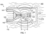
- FIG. 1 shows a fluid delivery device 100 according to an embodiment of the invention.
- the device 100 has a resonance chamber 110 forming a body portion of the device 100 and a fluid nozzle 120 arranged to supply a flow of gaseous fluid into the resonance chamber 110 through an outlet aperture 121 of the nozzle 120.
- the device 100 is operated to provide a flow of gas (such as air, nitrogen or other gas such as another inert gas) out from the nozzle 120 at a supersonic velocity of around 300ms -1 or greater. Other velocities are also useful.
- a flow of gas such as air, nitrogen or other gas such as another inert gas
- the nozzle 120 is arranged to provide the flow of gaseous fluid into the resonance chamber 110 in a direction towards a first end 111 of the chamber 110 being a closed end.
- the chamber 110 has openings 141, 142 arranged to allow gaseous fluid to flow out from the chamber 110.
- a receptor member 130 is provided in the resonance chamber 110.
- the receptor member 130 is in the form of a cupped member having walls 131 defining an open cavity 137, an opening 135 of the receptor member 130 facing in a direction towards the nozzle 120.
- the device 100 is arranged wherein gaseous fluid entering the resonance chamber 110 is directed to flow towards the opening 135 of the receptor member 130.
- the flow of gaseous fluid through the nozzle 120 is arranged to occur at a substantially constant rate and pressure. As the gaseous fluid exits the nozzle 120 the fluid expands generating a forward pressure wave travelling in a forward direction towards the receptor member 130.
- a portion of the forward pressure wave impinges on the receptor member 130.
- a pressure of fluid in the receptor member 130 thereby increases and a reverse pressure wave is generated, travelling in a reverse direction to the forward pressure wave.
- the reverse pressure wave may also be referred to as a 'reflected' pressure wave.
- the reverse pressure wave meets the forward pressure wave thus providing a 'feedback' mechanism to the propagation of the forward wave.
- Interaction of the forward and reverse waves as gaseous fluid exits the receptor member 130 may be arranged to result in the generation of an ultrasonic shockwave.
- Gaseous fluid entering the resonance chamber 110 is arranged to exit the resonance chamber 110 through a plurality of outlet conduits 141, 142.
- fluid exiting the resonance chamber 110 flows over an outer surface of the nozzle 120 in a substantially reverse direction to fluid entering the resonance chamber 110.
- the device 100 is arranged such that flow of gaseous fluid into the resonance chamber 110 from the nozzle 120 excites resonance of the chamber 110 at a resonant frequency of the device 100 whereby an ultrasonic shockwave may be transmitted into a medium 102 external to the chamber 110.
- the device 100 is arranged to be immersed in a liquid medium thereby to launch the ultrasonic shockwave into the liquid medium.
- a resonant frequency of the apparatus may depend on a distance between the outlet aperture 121 of the nozzle 120 and the receptor member 130.
- the position of the receptor member 130 is fixed.
- the distance between the receptor member 130 and the outlet aperture 121 of the nozzle 120 may be changed thereby to change a resonant frequency of the device 100.
- the position of the receptor member 130 may be changed by means of a screw mechanism thereby to 'tune' the resonant frequency to a desired frequency. Other arrangements are also useful.
- a resonant frequency of the device 100 may be important in applications where killing of aquatic nuisance species is desirable, such as bacterial species. This is because some bacteria may be more susceptible to death when exposed to ultrasonic waves of a prescribed frequency or range of frequencies than by ultrasonic waves of one or more other frequencies.
- FIG. 2 shows a fluid delivery device 200 according to a further embodiment of the invention. Like features of the device 200 of FIG. 2 to those of FIG. 1 are provided with similar reference numerals prefixed with numeral 2 instead of numeral 1.
- the device 200 has a resonance chamber 210 into which a nozzle 220 is arranged to provide a flow of gaseous fluid.
- a receptor member 230 is provided in a wall of the resonance chamber and positioned in a direct line of sight of gaseous fluid entering the resonance chamber 210 through the nozzle 220.
- the receptor member 230 is in the form of a cupped member.
- An external portion of the cupped member is arranged to be in direct thermal communication with an environment external to the device 200.
- impingement on the receptor member 230 of gaseous fluid flowing into the resonance chamber 210 causes resonance of the device 200 and the launching of ultrasonic shockwave into a liquid medium 202 in acoustic communication with the resonance chamber.
- the device 200 is thereby operable to kill certain ANS such as certain bacterial ANS.
- impingement of gaseous fluid on the receptor member 230 is arranged to cause heating of the receptor member 230.
- the temperature of the receptor member 230 may rise from ambient temperatures to a temperature in excess of 300°C or higher due to impingement of the gaseous fluid.
- liquid in which the device 200 is immersed may flow in contact with an external surface of the receptor member 230 resulting in heating of the liquid. This may further contribute to death of bacteria or other ANS present in the liquid.
- a fluid delivery device 100, 200 is provided in gas lift pump apparatus arranged to cause recirculation of liquid in a ballast tank of a maritime vessel.
- FIG. 3 shows a gas lift pump apparatus 350 installed in a substantially J-shaped ballast tank 395 of a vessel.
- the pump apparatus 350 may also be described as liquid circulation apparatus.
- the apparatus 350 has an immersion member 360 in the form of a substantially hollow tube member 360 provided in a substantially upright orientation within the ballast tank 395.
- the tube member 360 is substantially 'L'-shaped, having a bend portion 361 arranged to enable a liquid inlet 362 at a lower free end of the tube member 360 to project into a volume of the ballast tank that is displaced in a lateral (i.e. substantially horizontal) direction with respect to a free surface 397 of liquid within the tank 395 when the tank is filled to a level above this volume.
- the tube member has a liquid outlet 365 at an opposite end of the tube member 360 to the liquid inlet 362.
- the tube member 360 has two gas delivery devices 300A, 300B provided at vertically spaced apart locations along a length of the tube member 360.
- the delivery devices 300A, 300B are supplied with gas through respective fluid supply conduits 380A, 380B.
- the delivery devices 300A, 300B are each of the type shown in FIG. 1 .
- Other devices 300A, 300B are also useful, such as that shown in FIG. 2 or FIG. 6 (described below).
- Valves 362A, 362B are provided in conduits 380A, 380B respectively, upstream of the respective delivery devices 300A, 300B to allow the apparatus to control a flow of gas into the tube member 360.
- a liquid level sensor 371A, 371B is provided above each of the delivery devices 300A, 300B.
- the purpose of the liquid level sensor 371A, 371B is to provide a signal to a controller of the apparatus 350 indicating that a level of liquid has exceeded the level of the respective delivery device 300A, 300B.
- liquid level sensor 371A, 371B are also useful.
- a liquid level sensor may be provided that is arranged to determine a liquid level in the ballast tank 395 by measuring a head of pressure of liquid at a prescribed location, such as a location in a lower region of the tank 395, such as that labelled S in FIG. 3 .
- Other arrangements of one or more liquid level sensors are also useful.
- the apparatus is arranged to supply a flow of gas through delivery device 300A if the liquid level sensor 371A associated with device 300A indicates the presence of liquid at the level of sensor 371A unless liquid level sensor 371B indicates the presence of liquid at the level of sensor 371B.
- the apparatus is arranged to allow a flow of gas through delivery device 300B and not through delivery device 300A. This allows gas of a lower pressure to be employed to recirculate liquid in the ballast tank 395. This is because a head of pressure in the tank 395 at the level of device 300A is greater than that at the level of device 300B.
- the apparatus may be arranged to allow a flow of gas through the highest gas delivery device having a liquid level sensor 371A, 371B associated therewith indicating the presence of liquid at the level of that liquid level sensor 371A, 371B.
- the apparatus may be arranged to select a gas delivery device 300A, 300B through which a flow of gas is allowed based on a level of liquid in the fluid tank as determined by a separate fluid level measuring device such as a single fluid level measuring device at location S as discussed above.
- the tube member 360 (or 'column') has a plurality of apertures formed through the wall thereof as shown by the dashed outline of the tube member 360 in FIG. 3 .
- the apertures are arranged to allow fluid being pumped by the apparatus 350 to pass therethrough thereby to allow circulation (or 'recirculation') of liquid within the tank 395.
- liquid may flow out from the tube member 360 through outlet aperture 365 or through the apertures in the sidewall of the tube member 360.
- apertures may be provided in the tube member 360 or like component of each embodiment described herein or any other embodiment to enhance circulation of liquid. This feature has the advantage that liquid flowing through the tube member 360 is not required to flow all the way to a free end of the tube member 360 downstream of the flow of liquid through the tube member 360 in order to be expelled from the tube member 360.
- a flow path of liquid pumped by the apparatus 350 may be optimised for a given tank 395 in which the apparatus 350 is installed. Furthermore, in circumstances in which the tube member 360 is not fully immersed in liquid and the aperture 365 is exposed above a level of liquid in the tank 395 the apparatus 350 is not required to pump liquid above the level of liquid in the tank 395 in order to expel the liquid from the tube member 360.
- the apertures are large enough to allow passage of aquatic nuisance species therethrough in order to prevent blockage thereof. In some embodiments the apertures are large enough to allow passage therethrough of any other matter that might be expected to be found in the ballast water in order to prevent blockage of the apertures.
- the free end at which the outlet aperture 365 is provided is not required to have an aperture 365. Rather, the free end is a closed end and liquid pumped is required to flow out from the tube member 360 through the apertures in the sidewall of the tube member 360.
- FIG. 4 shows a further embodiment of the invention in which more than one tube member 460 is provided.
- more tube members 460A, 460B, 460C are provided. It is to be understood that any suitable number of tube members may be provided.
- each tube member 460A, 460B, 460C has a single gas delivery device 400A, 400B, 400C respectively coupled thereto through which gas may be forced into an inner volume 465A, 465B, 465C of the respective tube member 460A, 460B, 460C.
- Gas is supplied to each delivery device 400A, 400B, 400C by a respective gas supply conduit 480A, 480B, 480C.
- a valve 462A, 462B, 462C such as a check valve is provided in the respective conduit 480A, 480B, 480C upstream of each gas delivery device 400A, 400B, 400C in order to allow a flow of gas through each delivery device 400A, 400B, 400C to be controlled.
- Each tube member 460A, 460B, 460C has a liquid level sensor 471A, 471B, 471C respectively provided above the corresponding gas delivery device 400A, 400B, 400C.
- a level of liquid in the ballast tank 495 reaches or exceeds a level of a given liquid level sensor 471A, 471B, 471C
- the apparatus is arranged to allow gaseous fluid to pass into the corresponding tube member 460A, 460B, 460C associated with that level sensor 471A, 471B, 471C through the corresponding delivery device 400A, 400B, 400C.
- gaseous fluid is being supplied to any other tube member 460A, 460B, 460C when a further liquid level sensor 471A, 471B, 471C is actuated, supply of gaseous fluid to the other tube member 460A, 460B, 460C may be terminated, in a similar manner to the embodiment of FIG. 3 .
- Other arrangements are also useful.
- FIG. 1 or FIG. 2 may be used in the apparatus 450 of FIG. 4 .
- Other fluid delivery devices according to embodiments of the invention are also useful such as that of FIG. 6 as described below.
- FIG. 5 shows apparatus 550 according to an embodiment of the invention in which a tube member 560 is provided having a gas delivery device 500.
- the delivery device 500 is arranged to be movable in a vertical direction along at least a portion of a length of the tube member 560.
- the delivery device 500 is provided at a free end of a hose 580 arranged to be wound on a drum 585. It is to be understood that the delivery device 500 may be raised or lowered by rotation of the drum 585.
- the apparatus 550 is arranged to determine a level 597 of liquid in the fluid tank 595 and to position the gas delivery device 500 a suitable distance below the liquid level 597 to provide effective circulation of liquid in the tank.
- a fluid level monitoring device S is provided in a similar manner to that of the embodiment of FIG. 4 .
- the device arranged to determine the level of liquid in the tank 595.
- the apparatus 550 is arranged to determine a required vertical position of the gas delivery device 500 based on the level of liquid in the tank 595.
- the apparatus 550 may be arranged to raise the fluid delivery device 500 thereby to reduce a required pressure of gas flow along the hose 580 in order to force gas through the delivery device.
- the apparatus 550 may be arranged to lower the device 500 by a prescribed amount or to a prescribed level.
- the apparatus 550 is arranged to determine a level at which gaseous fluid is to be supplied to the delivery device 500 through the hose 580 by providing a prescribed pressure of gaseous fluid to the fluid delivery device 500 and lowering the device 500 until a flow rate of gaseous fluid through the device 500 falls to or below a prescribed value due to the increasing head of pressure at the device 500 as the device is lowered.
- the gas delivery device 500 may be arranged to be self-centering within the tube member 580. In other words, the gas delivery device 500 may be arranged to be positioned substantially coaxially of the tube member when gas is flowing out from the delivery device 500.
- the delivery device 500 has gas outlet apertures or outlet nozzles through which gas may flow out from the device 500.
- the apertures or nozzles may be arranged to cause the gas inlet 332 to be self-centering.
- the nozzles may be arranged to direct gas out from the delivery device 500 in a radial direction at circumferentially spaced positions thereby to provide a centering thrust on the device 500.
- FIG. 6 shows a fluid delivery device 600 according to a further embodiment of the invention.
- the device 600 is provided in a housing 601 arranged to be provided in a flowpath of fluid in a gas lift pump apparatus, i.e. the device is arranged to be mounted in the tube member of the gas lift pump apparatus.
- the device 600 has an upstream portion 601A and a downstream portion 601B as defined with respect to a direction in which fluid flow through the tube member is expected to occur during a pumping operation (normally an upward direction).
- the upstream portion of the device 600 houses a nozzle 620, a resonance chamber 610 and gaseous fluid outlets 641, 642.
- the downstream portion 601B of the housing 601 is tapered to reduce an amount of drag on a liquid flowing past the device 600 as it is pumped by the ejection of gas through the outlets 641, 642.
- the device 600 has a receptor member 630 coupled to an upstream portion of a wall of the housing 610 and protruding therethrough.
- the receptor member 630 projects to a location upstream of the housing 610. This promotes exposure of liquid flowing past the device 600 to the outer surface of the receptor member 630.
- the receptor member 630 is arranged to be heated by the flow of gaseous fluid through the device 600 whereby certain ANS may be killed.
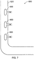
- FIG. 7 shows gas lift pump apparatus 650 according to an embodiment of the invention having a tube member 620 provided with three fluid delivery devices 600.
- the devices are provided at vertically spaced locations along the tube member 620.
- the devices 600 are provided at locations spaced apart from an inner wall of the tube member 620 away from a boundary layer of liquid flowing through the tube member 620. This increases an efficiency of the pump apparatus 650.
- embodiments of the invention have the advantage that ANS present in a liquid storage tank may be killed by passage of gaseous fluid through a fluid delivery device according to an embodiment of the present invention. This is at least in part because the delivery device is arranged to launch a shockwave into the liquid in the storage tank. As noted above, heating of bacteria or other ANS through contact with a receptor member at an elevated temperature may also contribute to death of ANS.
- the circulation of liquid through the pump apparatus enables the volume of liquid in the tank that may be exposed to the shockwave to be increased.
- the volume of liquid that may be treated by exposure to the shockwave may be increased.
- FIG. 8 shows a fluid delivery device 700 according to a further embodiment of the invention.
- the device 700 has a fluid nozzle 720 and a receptor member 730.
- the receptor member 730 has a cupped shape as in the case of the embodiments described above and defines a cavity 735.
- the nozzle member 720 is arranged to direct a flow of gaseous fluid into the cavity 735.
- the receptor member 730 is coupled to a fluid conduit or pipe 710 through which liquid may be arranged to flow.
- gaseous fluid is forced through the nozzle 720 and towards the cavity 735 of the receptor member 730.
- An ultrasonic shockwave is generated when the rate of flow of gaseous fluid through the nozzle 720 is sufficiently high.
- the device 700 is arranged such that the pipe 710 serves as a resonance chamber whereby the ultrasonic shockwave is launched into the liquid flowing through the pipe 710.
- the pipe 710 provides the column of a gas lift pump apparatus.
- the flow of gaseous fluid through the device 700 is further arranged such that gaseous fluid emanating from the nozzle ultimately flows into the pipe 710 thereby causing pumping of fluid in the pipe 710 by gas lift.
- apertures 741, 742 are provided in a wall of the pipe 710 to allow gaseous fluid into the pipe 710.
- the apertures 741, 742 are themselves arranged to generate an ultrasonic shockwave as gaseous fluid passes through them in addition to that generated by the flow of fluid from the nozzle 720 into the receptor member 730.
- the apertures 741, 742 may themselves act as 'whistles' to generate an ultrasonic shockwave.
- gaseous fluid may be introduced into the pipe 710 by alternative means, such as a conventional gaseous fluid injector not being arranged to generate an ultrasonic shockwave.
- a position of the receptor member 730 and nozzle 720 with respect to a length of the pipe 710 may be important in some embodiments in order to enable or enhance the launching of the ultrasonic shockwave into the pipe 710.
- the receptor member 730 and nozzle 720 are located a distance of around ⁇ /2 from one end of the pipe, where ⁇ is the wavelength of the ultrasonic shockwave, and a distance of around 3 ⁇ from an opposite end of the pipe. Other arrangements are also useful.
- the length and diameter of the pipe 710, the dimensions of the nozzle and receptor member configuration and the flow rate of fluid through the nozzle may be arranged to generate a desired frequency of shockwave to optimise killing of ANS.
- the gaseous fluid delivered by the fluid delivery device is arranged to kill ANS by increasing a concentration of the gaseous fluid in the liquid. It is to be understood that increasing the concentration of the gaseous fluid in the liquid may in turn result in a decrease in a concentration of one or more other gases in the liquid. For example, increasing the concentration of carbon dioxide in seawater is known to result in a decrease in the concentration of oxygen. This may alone or in addition contribute to death of one or more types of ANS.
- FIG. 9 is a schematic cross-sectional illustration of the fluid delivery device of FIG. 2 fitted with an amplification chamber 290.
- the chamber 290 has a substantially frusto-conical body portion 291 having a membrane 293 arranged to define a wall of the amplification chamber 290 at a basal (wider) end of the body portion 291.
- the chamber 290 is coupled to the device 200 such that an external surface of the receptor member 230 forms an apical wall of the chamber 290.
- the device 200 is arranged to direct shockwaves directly into the amplification chamber 290.
- the amplification chamber 290 is filled with gas and the device 200 is arranged such that in use the chamber 290 enables an increase in the amplitude of shockwaves launched into liquid 202 in which the device and chamber 290 are immersed. In some embodiments this is at least in part because the amplification chamber 290 is arranged to reduce a mismatch in impedance between the device 200 and the liquid 202 thereby more efficiently to communicate energy from the device 200 to the liquid 209.
- the amplification chamber 290 of the embodiment shown is formed from a metallic material. It is to be understood that other materials are also useful including plastics materials.
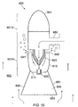
- FIG. 10 is a schematic illustration of a fluid delivery device 600 according to the embodiment of FIG. 6 fitted with an amplification chamber 690 similar to that of the embodiment of FIG. 9 .
- the chamber 690 is fitted to the device 600 so as to enclose the receptor member 630 such that the receptor member 630 provides a portion of a wall of the chamber 690.
- the device 600 is arranged to direct ultrasonic shockwaves directly into the chamber 690 which in turn directs the shockwaves into the surrounding liquid medium 602.
- the amplification chamber 690 is oriented so as to face upstream of the flow of liquid pumped.
- Other arrangements are also useful.
- the amplification chamber 690 may be arranged to face downstream of the flow of liquid pumped.
- the chamber 690 may be provided normal to a flow direction of liquid pumped.
- FIG. 11 is a schematic illustration of gas lift pump apparatus 750 according to an embodiment of the invention.
- the apparatus 750 has a substantially J-shaped liquid column 720 similar to that of the apparatus 650 of FIG. 7 .
- a fluid delivery device 600 similar to that shown in FIG. 10 is provided in the column 720 and oriented as shown.
- the amplification chamber 690 of the device 600 faces against a direction of flow of liquid L 1 pumped by the apparatus through the column 720.
- the amplification chamber 690 faces substantially vertically downwards.
- the apparatus 750 has a microbubble generator 770 upstream of the fluid delivery device 600.
- the microbubble generator 770 is positioned below the fluid delivery device 600.
- the generator 770 has a venturi portion 771 having the shape of a conventional venturi device.
- the venturi portion 771 is arranged such that liquid flowing through the column 720 is forced to flow through the venturi portion 771.
- the venturi has a converging portion C arranged to direct the liquid through a throat portion T and subsequently through a diverging portion D in the conventional manner.
- a liquid injector 775 is arranged to inject a flow of liquid L 2 into the column 720 upstream of the venturi portion 771.
- a cross-sectional view of the column 720 at position X-X is shown in FIG. 12 .
- the liquid injector 775 is configured to inject liquid L 2 into the column 720 in a direction substantially tangential to an inner surface 720S of the column 720 such that the liquid L2 has a component of velocity in a single angular direction within the column 720, i.e. the fluid swirls in substantially one direction. It is to be understood that the fluid will also have a component of velocity in an axial direction along the column 720 as it moves through the column 720. Thus, the injector 775 is arranged to promote the establishment of a flow vortex within the column 720.
- a gas injector 778 is arranged to inject a flow of gas 778F into the column 720 upstream of the venturi portion 771.
- the gas injector 778 is arranged to inject the gas at a position downstream of the liquid injector 775.
- the apparatus 750 is arranged such that as liquid from the liquid injector 775 and gas from the gas injector 778 enter the venturi portion 771 microbubbles are generated.
- the microbubbles act as sites to which bacterial ANS within the liquid may become attached.
- a probability of death of bacterial ANS by ultrasonic shockwaves produced by the fluid delivery device 600 is increased by the formation of the microbubbles. This is at least in part because the shockwaves can cause violent rupture of the microbubbles thereby causing damage and death to bacterial ANS trapped by a microbubble.
- the column 720 has a diameter of around 8 inches (around 20cm) and the liquid injector 775 has a diameter of around 2 inches (around 5cm). In the embodiment shown having these dimensions the injector 775 may be arranged to provide a liquid flow rate into the column 720 of around 200m 3 /h.
- the fluid delivery device 600 may be supplied with a gas flow rate of around 50 normal m 3 /h at a pressure of around 3.5-4.0 bar gauge (350-400kPa).
- microbubble generator 770 are operable more efficiently to destroy bacterial ANS.
- embodiments of the invention employing an amplification chamber 690 are also operable more efficiently to destroy bacterial ANS.
- FIG. 13 is a schematic illustration of gas lift pump apparatus 850 according to a further embodiment of the invention. Like features of the apparatus of FIG. 13 to those of the apparatus of FIG. 11 are labelled with identical reference signs or like reference signs prefixed numeral 8 instead of numeral 7.
- the apparatus 850 is similar to that of FIG. 11 except that the column 820 is closed at a lower end 820L such that the only liquid entering the column 820 at the lower end 820L is that from liquid injector 875.
- a gas injector 878 is arranged to deliver a flow of gas 878F into the column 820 immediately downstream of the liquid injector 875 and upstream of the venturi portion 871.
- the pumping rate of the apparatus 850 may be limited at least in part by the rate at which liquid L2 is injected into the column 820.
- the pumping rate may be limited by the rate at which liquid L2 and liquid L1 are able to pass through the column 720. It is to be understood that this rate may be controlled at least in part by the rate at which liquid L2 is forced into the column 720 and a rate at which gas is injected into the column 720 via gas injector 778 and fluid delivery device 600.
- FIG. 14(a) is a perspective view of a microbubble generator 970 suitable for use with embodiments of the present invention.
- the generator 970 has a body portion 970B having a liquid injector 975 and a gas injector 978 at one end arranged to inject liquid and gas, respectively, into an internal fluid conduit 973 of the generator 970.
- the conduit 973 is substantially circular in cross-section, the liquid injector 975 being arranged to inject liquid into the conduit 973 along a direction substantially tangential to the conduit 973 as viewed along a longitudinal axis of the conduit 973 similar to the arrangement of FIG. 12 . This is so as to promote establishment of a liquid flow vortex as the liquid passes along the conduit 973 towards a venturi portion 971. Establishment of the flow vortex promotes mixing of the gas and liquid.
- the generator 970 is operable to generate microbubbles in the liquid as the liquid and gas pass through the venturi portion 971.
- a flow of liquid having microbubbles entrained therein may be provided from a fluid outlet 972 of the generator 970.
- generator 970 and a fluid delivery device may be employed either in gas lift pump apparatus or separately in a ballast tank, a fluid conduit or any other suitable location.
- FIG. 15 shows an embodiment of the invention in which a fluid delivery device 600 is provided in a column 920 of a gas lift pump apparatus 950.
- a fluid delivery device 600 is provided in a column 920 of a gas lift pump apparatus 950.
- Like features of the apparatus of FIG. 15 to those of the apparatus of FIG. 11 are labelled with identical reference signs or like reference signs prefixed numeral 9 instead of numeral 7.
- a microbubble generator 970 substantially as described above and illustrated in FIG. 14 is mounted in the column 920 of the apparatus 950.
- the generator 970 is operable to inject a flow of liquid L 2 in which microbubbles are entrained into the column 920 via outlet 972 and towards the fluid delivery device 600. It is to be understood that the apparatus 950 is also operable to pump liquid L 1 through the column from an inlet 9201 of the column 920 by gas lift, by means of gas injected into the column via the fluid delivery device 600, as well as by a pressure of liquid injected into the column 920 via liquid injector 975 of the generator 970.
- injection of gas into the column 920 in the form of microbubbles by means of gas injector 975 may also assist in pumping liquid L 1 through the column 920 by gas lift.
- a microbubble generator 970 provides a flow of entrained microbubbles to a fluid delivery device according to an embodiment of the invention.
- Embodiments of the invention are operable to kill bacterial ANS as well as non-bacterial ANS.
- the generator 970 is shown positioned in the flowstream of liquid L1.
- the generator 970 may alternatively be provided at a base of a column having a closed lower end, such as the end 820L of the column 820 of the embodiment of FIG. 13 .
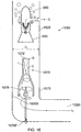
- FIG. 16 is a schematic illustration of gas lift pump apparatus 1050 according to a further embodiment of the invention. Like features of the apparatus of FIG. 16 to those of the apparatus of FIG. 15 are labelled with like reference signs prefixed '10' instead of numeral 9.
- the apparatus 1050 of FIG. 16 is similar to that of FIG. 15 in that it has a substantially J-shaped gas lift column 1020 having a fluid delivery device 600 provided therein. It is to be understood that apparatus according to embodiments of the invention may have any number of fluid delivery devices 600 provided therein.
- the apparatus 1050 has a microbubble generator 1070 provided upstream of the fluid delivery device 600.
- the generator 1070 is similar to that of the embodiment of FIG. 15 except that the generator 1070 does not have a liquid injector 975. Instead, an upstream end of the generator 1070 is arranged to receive a flow of liquid L1 entering the column 1020 through an inlet 10201 at the upstream end of the column 1020. (In the embodiment shown the upstream end is also the lowermost end). It can be seen that a portion of the liquid L 1 entering the column 1020 through the inlet 10201 flows around an outside of the generator 1070. However a portion of the liquid flows through the generator 1070.
- a flow of gas 1078F is provided through the generator 1070 by means of a gas injector 1078.
- the injector 1078 is arranged such that as liquid L 1 flows therethrough microbubbles are formed in the liquid L 1 .
- the column is 1020 is arranged to introduce swirl into the liquid L1 once it has entered the column 1020 through the inlet 10201.
- Swirl is useful in encouraging the formation of microbubbles in the flow of liquid L 1 through the generator 1070 as discussed above.
- the generator 1070 is arranged to introduce swirl in liquid entering the generator 1070.
- flow deflectors may be provided around the injector 1078 or other portion such as an inner wall of the generator 1070 to induce swirl in liquid L1 entering the generator 1070.
- FIG. 17 is a schematic illustration of gas lift pump apparatus 1150 according to a further embodiment of the invention. Like features of the apparatus of FIG. 17 to those of the apparatus of FIG. 15 are labelled with like reference signs prefixed '11' instead of numeral 9.
- FIG. 17 is similar to that of FIG. 16 in that the microbubble generator does not have a separate liquid injector, unlike the generator 970 of FIG. 15 .
- the column 1120 is substantially J-shaped and has an inlet 11201 at an end of the column 920 being a lowermost end.
- the generator 1170 of the apparatus 1150 of FIG. 17 is similar to that of the embodiment of FIG. 13 in that substantially all liquid L 1 entering the column (at the single liquid inlet 10201) passes through the generator 1170. That is, none (or substantially none) of the liquid L 1 passing through the inlet 11201 passes around the generator 1170, but rather passes through the venturi portion defined by the generator 1170.
- the apparatus 1150 is again arranged to induce swirl of the liquid L 1 entering the column 1120 so as to encourage the formation of microbubbles by intimate mixing of the gas flow 1178F injected upstream of the generator 1170 and liquid L 1 .
- swirl of the liquid L 1 is induced by introducing the flow of liquid L 1 into the vertical portion of the column 1020, 1120 along a direction tangential to an inner surface 1020S, 1120S of the column 1020, 1120.
- Other arrangements are also useful.
- guide elements such as vanes or other elements arranged to induce rotational motion of the fluid within the column 1020, 1120 may also be provided.
- Reference herein to a vessel includes reference to any boat, ship or other floating structure having at least one ballast tank in the form of a liquid storage tank.
Landscapes
- Engineering & Computer Science (AREA)
- Mechanical Engineering (AREA)
- General Engineering & Computer Science (AREA)
- Physical Water Treatments (AREA)
- Physical Or Chemical Processes And Apparatus (AREA)
- Jet Pumps And Other Pumps (AREA)
- Special Spraying Apparatus (AREA)
- Life Sciences & Earth Sciences (AREA)
- Health & Medical Sciences (AREA)
- Chemical & Material Sciences (AREA)
- Magnetic Resonance Imaging Apparatus (AREA)
- Paper (AREA)
- Transmitters (AREA)
- Environmental & Geological Engineering (AREA)
- General Health & Medical Sciences (AREA)
- Public Health (AREA)
- Toxicology (AREA)
- Surgical Instruments (AREA)
- Combustion & Propulsion (AREA)
- Ocean & Marine Engineering (AREA)
- Devices For Conveying Motion By Means Of Endless Flexible Members (AREA)
- Insects & Arthropods (AREA)
- Pest Control & Pesticides (AREA)
- Wood Science & Technology (AREA)
- Zoology (AREA)
- Environmental Sciences (AREA)
Description
- The present invention relates to a shockwave generation device and to a method of delivering a shockwave. In particular but not exclusively the invention relates to a shockwave generation device for delivering a flow of fluid into a gas lift pump apparatus.
- It is known to provide a gas lift pump for pumping a fluid such as a liquid or sludge.
JP2007113295 -
JP1207535 - In an entirely separate technical field, the problem exists that aquatic nuisance species (ANS) such as Zebra mussels are being transported between locations such as between the US and Asia in the ballast tanks of maritime vessels. Aquatic nuisance species may be defined as waterborne, non-native organisms that threaten the diversity or abundance of native species, the ecological stability of impacted waters or commercial, agricultural, aquacultural or recreational activities. A variety of measures for preventing invasion of an environment by ANS have been proposed, including purging of ballast tanks at sea before a vessel enters an area sensitive to ANS.
- However, purging of a ballast tank requires emptying and refilling of the ballast tank. It will be understood that such a procedure can have an adverse effect on the stability of a vessel particularly in rough seas and is not appropriate in certain cases.
- It is also known to kill ANS by pumping inert gas into seawater. The inert gas can for example be supplied by or derived from the combustion gases of a marine engine such as a diesel engine.
- Embodiments of the present invention may be understood with reference to the appended claims.
- In an aspect of the invention there is provided gas lift pump apparatus comprising a column through which a liquid medium may be pumped by gas lift, the apparatus comprising a fluid delivery device for delivering a flow of a gaseous fluid into the liquid medium, the device comprising means for generating an ultrasonic shockwave by the flow of gaseous fluid therethrough, the device being operable to launch the ultrasonic shockwave into the liquid medium in the column.
- In one aspect of the invention there is provided a fluid delivery device for delivering a flow of a gaseous fluid into a liquid medium, the device comprising means for generating an ultrasonic shockwave under the flow of gaseous fluid therethrough, the device being operable to launch the ultrasonic shockwave into the liquid medium.
- Embodiments of the invention have the advantage that a gaseous fluid may be delivered into a liquid in a ballast tank of a vessel in order to kill aquatic nuisance species by exposure of the species to the shockwave.
- Furthermore, embodiments of the invention allow a concentration of the gaseous fluid in the liquid medium to be increased whilst at the same time generating the ultrasonic shockwave. This allows the apparatus to be employed to kill aquatic nuisance species (ANS) both by increasing the concentration of the gaseous fluid in the liquid medium and by means of passage of the ultrasonic shockwave through the liquid medium.
- In some applications the ultrasonic shockwave is arranged to kill bacteria present in the liquid medium, such as one or more of toxicogenic vibrio cholerae, Escherichia coli (E. coli) and intestinal enterococci.
- Some embodiments of the invention employ an arrangement similar to that of a Hartmann whistle in order to generate ultrasonic shockwaves.
- Preferably the device comprises a resonance chamber, the device being operable to excite the resonance chamber at a resonant frequency of the apparatus due to flow of the gaseous fluid through the device thereby to launch the ultrasonic shockwave.
- Preferably the resonance chamber comprises a receptor member, the receptor member being arranged to reflect a pressure wave generated by passage of the gaseous fluid through the device thereby to generate the ultrasonic shockwave.
- The receptor member may be provided by at least a portion of a wall of the resonance chamber.
- Alternatively or in addition the receptor member may be provided by a member within the resonance chamber.
- Preferably the device is operable to cause the gaseous fluid to pass into the resonance chamber thereby to excite the resonance chamber.
- Preferably the device is operable wherein gaseous fluid entering the resonance chamber impinges upon the receptor member.
- The receptor member preferably comprises a cupped portion, the device being arranged to direct a flow of gaseous fluid into the cupped portion of the receptor member, the receptor member being arranged in turn to redirect the flow of gaseous fluid out from the cupped portion.
- Preferably, the device is arranged wherein impingement of gaseous fluid on the receptor member causes heating of the receptor member.
- The device maybe operable wherein heating of the receptor member causes heating of the liquid medium.
- Preferably the receptor member is provided in thermal communication with a surface of the device in thermal communication with the liquid medium.
- The device preferably comprises a nozzle member, the nozzle member being arranged to deliver the flow of gaseous fluid into the resonance chamber.
- The device is preferably operable to cause a pressure standing wave to be established in the resonance chamber. Preferably the pressure standing wave is an ultrasonic standing wave.
- Preferably the resonant frequency of the device may be operably changed from a first value to a second value.
- Preferably the resonant frequency of the device may be operably changed by changing a position of the receptor member.
- Optionally the resonant frequency of the device may be operably changed by changing a position of the receptor member with respect to the nozzle member.
- The resonance chamber may comprise a fluid outlet, the device being arranged wherein gaseous fluid flowing through the resonance chamber may exit the resonance chamber through the fluid outlet.
- The device may be provided with amplification means for increasing an amplitude of the ultrasonic shockwave launched into the medium.
- The amplification means may comprise means for reducing a mismatch between an impedance of the device and an impedance of the liquid medium.
- The amplification means may comprise an amplification chamber, the amplification chamber being acoustically coupled to the device.
- The amplification chamber may comprise a gas filled chamber.
- The amplification chamber may have a cross-sectional area that increases as a function of distance from the device.
- The amplification chamber may have a substantially tapered cross-section.
- The amplification chamber preferably has a substantially conical shape.
- The amplification chamber may have a substantially frusto-conical shape.
- At least one wall of the chamber may comprise a resiliently flexible membrane arranged to transmit at least a portion of the ultrasonic shockwave into the liquid medium.
- The resiliently flexible membrane may comprise one selected from amongst a metallic membrane and a polymer membrane.
- Preferably the device is arranged to be provided in a flow-stream of the liquid medium, the device having an upstream portion and a downstream portion.
- The upstream portion and/or the downstream portion may be tapered thereby to reduce an amount of drag experienced by the device in the flow-stream of the liquid medium.
- Preferably the upstream portion comprises the receptor member.
- The gaseous fluid is preferably an inert gas.
- The device is preferably operable to kill at least one aquatic nuisance species by means of the ultrasonic shockwave launched by the device.
- The device may be arranged whereby an aperture by means of which gaseous fluid passes from the device into the liquid medium is arranged to generate an ultrasonic wave by passage of the gaseous fluid therethrough.
- In a further aspect of the invention there is provided gas lift pump apparatus comprising a column through which liquid is pumped by gas lift, the apparatus comprising a fluid delivery device according to the first aspect.
- Gaseous fluid flowing through the device may be arranged to pass into the column of the gas lift pump apparatus thereby to cause pumping of the liquid medium.
- Preferably pumping of the liquid medium by the gaseous fluid occurs by gas lift.
- The fluid delivery device may be provided in a flowpath of fluid through the column.
- Alternatively the device may be provided at a location that is recessed radially outwardly with respect to an inner wall of the column. For example the device may be provided at a location that is displaced radially outwardly with respect to the inner wall so that it does not lie in a direct flowpath of fluid through the column. In some arrangements the device may be at least partially recessed with respect to the wall of the column.
- The column may be of a substantially circular cross-section or any other suitable cross-sectional shape such as elliptical, square or any other suitable shape.
- Preferably the apparatus is operable to kill ANS present in the liquid by means of the ultrasonic shockwave generated by the device.
- Preferably the apparatus further comprises a microbubble generator.
- Preferably the microbubble generator is arranged to generate microbubbles upstream of the device.
- The microbubble generator may comprise a venturi portion, the venturi portion having a converging section, a throat section and a diverging section.
- The apparatus may be arranged to generate a flow of liquid into the venturi in the form of a vortex thereby to generate microbubbles in the liquid.
- The apparatus is preferably arranged to generate a flow of liquid into the venturi in the form of a vortex by injecting a flow of liquid into the column of the apparatus.
- The apparatus may be arranged to generate a flow of liquid into the venturi in the form of a vortex by injecting a flow of liquid into the column of the apparatus in a direction substantially tangential to the column.
- The microbubbles may have a diameter in the range of at least one selected from amongst from around 1 micron to around 1000 microns, around 1 micron to around 500 microns, around 1 micron to around 100 microns, around 1 micron to around 10microns and around 10 microns to around 100 microns.
- The column may have one or more apertures in a sidewall thereof to allow flow of liquid that is pumped by the apparatus to flow therethrough.
- This has the advantage that circulation of liquid in a volume of water in which the apparatus is provided may be enhanced.
- Advantageously the column has a plurality of apertures formed in the sidewall thereof.
- An end of the column downstream of the flow of liquid may be closed thereby to force liquid flowing through the column to flow out from the column through the apertures.
- In a still further aspect of the invention there is provided a method of delivering gaseous fluid into a liquid medium comprising the steps of: providing a flow of a gaseous fluid through a fluid delivery device, the device being arranged wherein the flow of gaseous fluid through the device causes the device to launch an ultrasonic shockwave into the gaseous fluid.
- Preferably the gaseous fluid is selected whereby increasing a concentration of the gaseous fluid in the liquid medium to a sufficiently high value results in death of at least one ANS present in the liquid medium.
- The gaseous fluid may comprise an inert gas.
- The gaseous fluid may comprise at least one selected from amongst carbon dioxide, nitrogen and oxygen.
- The gaseous fluid may substantially comprise carbon dioxide, nitrogen and oxygen.
- The gaseous fluid may consist essentially of carbon dioxide, nitrogen and oxygen.
- Alternatively the gaseous fluid may be carbon dioxide.
- The gaseous fluid may comprise one or more combustion gases.
- Preferably the liquid medium is ballast water of a vessel.
- More preferably the liquid medium is ballast water in a ballast tank of a vessel.
- Preferably, the method comprises generating an ultrasonic shockwave by passage of gaseous fluid through an aperture from the device into the liquid medium.
- The method may further comprise producing microbubbles in the liquid medium and launching the ultrasonic shockwave into the liquid medium containing the microbubbles.
- The method preferably comprises trapping ANS present in the liquid medium in or on a microbubble.
- Preferably the method further comprises killing the ANS by means of the ultrasonic shockwave.
- In another aspect of the invention there is provided a method of killing aquatic nuisance species comprising the steps of: providing a flow of a gaseous fluid through a fluid delivery device, the device being arranged wherein the flow of gaseous fluid through the device causes the device to launch an ultrasonic shockwave into the liquid medium thereby to kill aquatic nuisance species therein.
- In an aspect of the invention there is provided a liquid storage tank comprising a device according to the first aspect.
- In one aspect of the invention there is provided a ballast tank for a marine vessel comprising a device according to the first aspect.
- In a further aspect of the invention there is provided a vessel having a ballast tank comprising a device according to the first aspect.
- In a still further aspect of the invention there is provided a liquid storage tank comprising apparatus according to the second aspect of the invention.
- In another aspect of the invention there is provided a ballast tank for a marine vessel comprising apparatus according to the second aspect of the invention.
- In a further aspect of the invention there is provided a vessel having a ballast tank comprising apparatus according to the second aspect of the invention.
- In one embodiment there is provided a fluid delivery device for delivering a flow of a gaseous fluid into a liquid medium, the device being operable wherein the flow of gaseous fluid through the device causes the device to launch ultrasonic shockwaves into the liquid medium.
- It is to be understood that some embodiments of the invention provide a Hartmann-type whistle structure to launch an ultrasonic shockwave into a liquid medium. In addition, some embodiments of the invention are arranged to inject gas flowing through the whistle structure into the liquid medium.
- Some embodiments of the invention are employed in combination with a gas lift pump to cause pumping or recirculation of liquid in a tank such as a ballast tank of a vessel.
- Some embodiments of the invention are arranged to kill ANS and in particular bacterial and/or viral or similar ANS by means of the ultrasonic shockwave. Other arrangements are also useful.
- In addition, in some embodiments the whistle is arranged to have a gas passed therethrough that is arranged to kill one or more ANS, for example by hypoxia and/or hypercapnia.
- Embodiments of the invention will now be described with reference to the accompanying figures in which:
-
FIGURE 1 is a cross-sectional schematic illustration of a fluid delivery device according to an embodiment of the invention; -
FIGURE 2 is a cross-sectional schematic illustration of a fluid delivery device according to a further embodiment of the invention; -
FIGURE 3 is a schematic illustration of a gas lift pump apparatus according to an embodiment of the invention installed in a ballast tank of a vessel; -
FIGURE 4 is a schematic illustration of a gas lift pump apparatus according to a further embodiment of the invention installed in a ballast tank of a vessel; -
FIGURE 5 is a schematic illustration of a gas lift pump apparatus according to a still further embodiment of the invention installed in a ballast tank of a vessel; -
FIGURE 6 is a cross-sectional schematic illustration of a fluid delivery device according to a further embodiment of the invention; -
FIGURE 7 is a schematic illustration of a gas lift pump apparatus according to an embodiment of the invention provided with a fluid delivery device according to the embodiment ofFIG. 6 ; -
FIGURE 8 is a schematic illustration of a fluid delivery device according to an embodiment of the invention; -
FIGURE 9 is a cross-sectional schematic illustration of a fluid delivery device according to a further embodiment of the invention; -
FIGURE 10 is a cross-sectional schematic illustration of a fluid delivery device according to a still further embodiment of the invention; -
FIGURE 11 is a cross-sectional schematic illustration of a gas lift pump apparatus according to an embodiment of the invention provided with a fluid delivery device according to the embodiment ofFIG. 10 ; -
FIGURE 12 is a cross-sectional view of a column of the gas lift apparatus ofFIG. 11 showing the orientation of a tangential fluid injection port; -
FIGURE 13 is a cross-sectional schematic illustration of a gas lift pump apparatus according to a further embodiment of the invention provided with a fluid delivery device according to the embodiment ofFIG. 10 ; -
FIGURE 14 shows a microbubble generator suitable for use in some embodiments of the invention in (a) perspective view, (b) side view, (c) front view and (d) top view; -
FIGURE 15 shows gas lift pump apparatus according to an embodiment of the invention having the generator ofFIG. 14 and a fluid delivery device according to the embodiment ofFIG. 10 ; -
FIGURE 16 shows gas lift pump apparatus according to a further embodiment of the invention having the fluid delivery device of the embodiment ofFIG. 10 ; and -
FIGURE 17 shows gas lift pump apparatus according to a still further embodiment of the invention having the fluid delivery device of the embodiment ofFIG. 10 . -
FIG. 1 shows afluid delivery device 100 according to an embodiment of the invention. Thedevice 100 has aresonance chamber 110 forming a body portion of thedevice 100 and afluid nozzle 120 arranged to supply a flow of gaseous fluid into theresonance chamber 110 through anoutlet aperture 121 of thenozzle 120. In some embodiments thedevice 100 is operated to provide a flow of gas (such as air, nitrogen or other gas such as another inert gas) out from thenozzle 120 at a supersonic velocity of around 300ms-1 or greater. Other velocities are also useful. - In the embodiment shown the
nozzle 120 is arranged to provide the flow of gaseous fluid into theresonance chamber 110 in a direction towards afirst end 111 of thechamber 110 being a closed end. - At a
second end 112 opposite thefirst end 111 thechamber 110 hasopenings chamber 110. - In the embodiment of
FIG. 1 areceptor member 130 is provided in theresonance chamber 110. Thereceptor member 130 is in the form of a cuppedmember having walls 131 defining anopen cavity 137, anopening 135 of thereceptor member 130 facing in a direction towards thenozzle 120. - The
device 100 is arranged wherein gaseous fluid entering theresonance chamber 110 is directed to flow towards the opening 135 of thereceptor member 130. - The flow of gaseous fluid through the
nozzle 120 is arranged to occur at a substantially constant rate and pressure. As the gaseous fluid exits thenozzle 120 the fluid expands generating a forward pressure wave travelling in a forward direction towards thereceptor member 130. - A portion of the forward pressure wave impinges on the
receptor member 130. A pressure of fluid in thereceptor member 130 thereby increases and a reverse pressure wave is generated, travelling in a reverse direction to the forward pressure wave. The reverse pressure wave may also be referred to as a 'reflected' pressure wave. - The reverse pressure wave meets the forward pressure wave thus providing a 'feedback' mechanism to the propagation of the forward wave. Interaction of the forward and reverse waves as gaseous fluid exits the
receptor member 130 may be arranged to result in the generation of an ultrasonic shockwave. - Gaseous fluid entering the
resonance chamber 110 is arranged to exit theresonance chamber 110 through a plurality ofoutlet conduits FIG. 1 , fluid exiting theresonance chamber 110 flows over an outer surface of thenozzle 120 in a substantially reverse direction to fluid entering theresonance chamber 110. - The
device 100 is arranged such that flow of gaseous fluid into theresonance chamber 110 from thenozzle 120 excites resonance of thechamber 110 at a resonant frequency of thedevice 100 whereby an ultrasonic shockwave may be transmitted into a medium 102 external to thechamber 110. In the embodiment shown thedevice 100 is arranged to be immersed in a liquid medium thereby to launch the ultrasonic shockwave into the liquid medium. - It is to be understood that a resonant frequency of the apparatus may depend on a distance between the
outlet aperture 121 of thenozzle 120 and thereceptor member 130. In the embodiment shown the position of thereceptor member 130 is fixed. In some embodiments the distance between thereceptor member 130 and theoutlet aperture 121 of thenozzle 120 may be changed thereby to change a resonant frequency of thedevice 100. In some embodiments the position of thereceptor member 130 may be changed by means of a screw mechanism thereby to 'tune' the resonant frequency to a desired frequency. Other arrangements are also useful. - It is to be understood that the selection of a resonant frequency of the
device 100 may be important in applications where killing of aquatic nuisance species is desirable, such as bacterial species. This is because some bacteria may be more susceptible to death when exposed to ultrasonic waves of a prescribed frequency or range of frequencies than by ultrasonic waves of one or more other frequencies. -
FIG. 2 shows afluid delivery device 200 according to a further embodiment of the invention. Like features of thedevice 200 ofFIG. 2 to those ofFIG. 1 are provided with similar reference numerals prefixed withnumeral 2 instead of numeral 1. - The
device 200 has aresonance chamber 210 into which anozzle 220 is arranged to provide a flow of gaseous fluid. Areceptor member 230 is provided in a wall of the resonance chamber and positioned in a direct line of sight of gaseous fluid entering theresonance chamber 210 through thenozzle 220. - As in the embodiment of
FIG. 1 thereceptor member 230 is in the form of a cupped member. An external portion of the cupped member is arranged to be in direct thermal communication with an environment external to thedevice 200. - In use, impingement on the
receptor member 230 of gaseous fluid flowing into theresonance chamber 210 causes resonance of thedevice 200 and the launching of ultrasonic shockwave into aliquid medium 202 in acoustic communication with the resonance chamber. Thedevice 200 is thereby operable to kill certain ANS such as certain bacterial ANS. - Furthermore, impingement of gaseous fluid on the
receptor member 230 is arranged to cause heating of thereceptor member 230. Under certain conditions the temperature of thereceptor member 230 may rise from ambient temperatures to a temperature in excess of 300°C or higher due to impingement of the gaseous fluid. It is to be understood that, advantageously, liquid in which thedevice 200 is immersed may flow in contact with an external surface of thereceptor member 230 resulting in heating of the liquid. This may further contribute to death of bacteria or other ANS present in the liquid. - In some applications a
fluid delivery device -
FIG. 3 shows a gaslift pump apparatus 350 installed in a substantially J-shapedballast tank 395 of a vessel. Thepump apparatus 350 may also be described as liquid circulation apparatus. - The
apparatus 350 has animmersion member 360 in the form of a substantiallyhollow tube member 360 provided in a substantially upright orientation within theballast tank 395. - In the embodiment shown the
tube member 360 is substantially 'L'-shaped, having abend portion 361 arranged to enable aliquid inlet 362 at a lower free end of thetube member 360 to project into a volume of the ballast tank that is displaced in a lateral (i.e. substantially horizontal) direction with respect to afree surface 397 of liquid within thetank 395 when the tank is filled to a level above this volume. The tube member has aliquid outlet 365 at an opposite end of thetube member 360 to theliquid inlet 362. - The
tube member 360 has twogas delivery devices tube member 360. Thedelivery devices fluid supply conduits - In the embodiment shown the
delivery devices FIG. 1 .Other devices FIG. 2 orFIG. 6 (described below). -
Valves conduits respective delivery devices tube member 360. - In the embodiment shown in
FIG. 3 aliquid level sensor delivery devices liquid level sensor apparatus 350 indicating that a level of liquid has exceeded the level of therespective delivery device - Other locations of
liquid level sensor ballast tank 395 by measuring a head of pressure of liquid at a prescribed location, such as a location in a lower region of thetank 395, such as that labelled S inFIG. 3 . Other arrangements of one or more liquid level sensors are also useful. - The apparatus is arranged to supply a flow of gas through
delivery device 300A if theliquid level sensor 371A associated withdevice 300A indicates the presence of liquid at the level ofsensor 371A unlessliquid level sensor 371B indicates the presence of liquid at the level ofsensor 371B. In this case, the apparatus is arranged to allow a flow of gas throughdelivery device 300B and not throughdelivery device 300A. This allows gas of a lower pressure to be employed to recirculate liquid in theballast tank 395. This is because a head of pressure in thetank 395 at the level ofdevice 300A is greater than that at the level ofdevice 300B. - It is to be understood that more than two
fluid delivery devices liquid level sensors liquid level sensor liquid level sensor - Other arrangements are also useful. Thus, the apparatus may be arranged to select a
gas delivery device - The tube member 360 (or 'column') has a plurality of apertures formed through the wall thereof as shown by the dashed outline of the
tube member 360 inFIG. 3 . The apertures are arranged to allow fluid being pumped by theapparatus 350 to pass therethrough thereby to allow circulation (or 'recirculation') of liquid within thetank 395. Thus liquid may flow out from thetube member 360 throughoutlet aperture 365 or through the apertures in the sidewall of thetube member 360. - It is to be understood that apertures may be provided in the
tube member 360 or like component of each embodiment described herein or any other embodiment to enhance circulation of liquid. This feature has the advantage that liquid flowing through thetube member 360 is not required to flow all the way to a free end of thetube member 360 downstream of the flow of liquid through thetube member 360 in order to be expelled from thetube member 360. - This has the advantage that a flow path of liquid pumped by the
apparatus 350 may be optimised for a giventank 395 in which theapparatus 350 is installed. Furthermore, in circumstances in which thetube member 360 is not fully immersed in liquid and theaperture 365 is exposed above a level of liquid in thetank 395 theapparatus 350 is not required to pump liquid above the level of liquid in thetank 395 in order to expel the liquid from thetube member 360. - In some embodiments the apertures are large enough to allow passage of aquatic nuisance species therethrough in order to prevent blockage thereof. In some embodiments the apertures are large enough to allow passage therethrough of any other matter that might be expected to be found in the ballast water in order to prevent blockage of the apertures.
- In some arrangements the free end at which the
outlet aperture 365 is provided, as shown inFIG. 3 , is not required to have anaperture 365. Rather, the free end is a closed end and liquid pumped is required to flow out from thetube member 360 through the apertures in the sidewall of thetube member 360. -
FIG. 4 shows a further embodiment of the invention in which more than one tube member 460 is provided. In the embodiment ofFIG. 4 threetube members - In the embodiment shown each
tube member gas delivery device inner volume respective tube member delivery device gas supply conduit - A
valve respective conduit gas delivery device delivery device - Each
tube member liquid level sensor gas delivery device ballast tank 495 reaches or exceeds a level of a givenliquid level sensor tube member level sensor corresponding delivery device - If gaseous fluid is being supplied to any
other tube member liquid level sensor other tube member FIG. 3 . Other arrangements are also useful. - It is to be understood that the fluid delivery devices of
FIG. 1 orFIG. 2 may be used in theapparatus 450 ofFIG. 4 . Other fluid delivery devices according to embodiments of the invention are also useful such as that ofFIG. 6 as described below. -
FIG. 5 shows apparatus 550 according to an embodiment of the invention in which atube member 560 is provided having agas delivery device 500. Thedelivery device 500 is arranged to be movable in a vertical direction along at least a portion of a length of thetube member 560. In the embodiment shown thedelivery device 500 is provided at a free end of ahose 580 arranged to be wound on adrum 585. It is to be understood that thedelivery device 500 may be raised or lowered by rotation of thedrum 585. - The
apparatus 550 is arranged to determine alevel 597 of liquid in thefluid tank 595 and to position the gas delivery device 500 a suitable distance below theliquid level 597 to provide effective circulation of liquid in the tank. - In some embodiments a fluid level monitoring device S is provided in a similar manner to that of the embodiment of
FIG. 4 . The device arranged to determine the level of liquid in thetank 595. Theapparatus 550 is arranged to determine a required vertical position of thegas delivery device 500 based on the level of liquid in thetank 595. - Thus, if the level of liquid in the
tank 595 rises, theapparatus 550 may be arranged to raise thefluid delivery device 500 thereby to reduce a required pressure of gas flow along thehose 580 in order to force gas through the delivery device. Similarly, if the level of liquid falls, e.g. below a prescribed level, theapparatus 550 may be arranged to lower thedevice 500 by a prescribed amount or to a prescribed level. - In some embodiments, instead of providing a fluid level monitoring device, the
apparatus 550 is arranged to determine a level at which gaseous fluid is to be supplied to thedelivery device 500 through thehose 580 by providing a prescribed pressure of gaseous fluid to thefluid delivery device 500 and lowering thedevice 500 until a flow rate of gaseous fluid through thedevice 500 falls to or below a prescribed value due to the increasing head of pressure at thedevice 500 as the device is lowered. - Other arrangements are also useful.
- The
gas delivery device 500 may be arranged to be self-centering within thetube member 580. In other words, thegas delivery device 500 may be arranged to be positioned substantially coaxially of the tube member when gas is flowing out from thedelivery device 500. - In some embodiments the
delivery device 500 has gas outlet apertures or outlet nozzles through which gas may flow out from thedevice 500. The apertures or nozzles may be arranged to cause the gas inlet 332 to be self-centering. - In some embodiments the nozzles may be arranged to direct gas out from the
delivery device 500 in a radial direction at circumferentially spaced positions thereby to provide a centering thrust on thedevice 500. -
FIG. 6 shows afluid delivery device 600 according to a further embodiment of the invention. Thedevice 600 is provided in ahousing 601 arranged to be provided in a flowpath of fluid in a gas lift pump apparatus, i.e. the device is arranged to be mounted in the tube member of the gas lift pump apparatus. - Accordingly the
device 600 has anupstream portion 601A and adownstream portion 601B as defined with respect to a direction in which fluid flow through the tube member is expected to occur during a pumping operation (normally an upward direction). - The upstream portion of the
device 600 houses anozzle 620, aresonance chamber 610 and gaseousfluid outlets - The
downstream portion 601B of thehousing 601 is tapered to reduce an amount of drag on a liquid flowing past thedevice 600 as it is pumped by the ejection of gas through theoutlets - The
device 600 has areceptor member 630 coupled to an upstream portion of a wall of thehousing 610 and protruding therethrough. In the embodiment ofFIG. 6 thereceptor member 630 projects to a location upstream of thehousing 610. This promotes exposure of liquid flowing past thedevice 600 to the outer surface of thereceptor member 630. - In some embodiments such as that of
FIG. 6 thereceptor member 630 is arranged to be heated by the flow of gaseous fluid through thedevice 600 whereby certain ANS may be killed. -
FIG. 7 shows gaslift pump apparatus 650 according to an embodiment of the invention having atube member 620 provided with threefluid delivery devices 600. The devices are provided at vertically spaced locations along thetube member 620. Furthermore thedevices 600 are provided at locations spaced apart from an inner wall of thetube member 620 away from a boundary layer of liquid flowing through thetube member 620. This increases an efficiency of thepump apparatus 650. - It is to be understood that embodiments of the invention have the advantage that ANS present in a liquid storage tank may be killed by passage of gaseous fluid through a fluid delivery device according to an embodiment of the present invention. This is at least in part because the delivery device is arranged to launch a shockwave into the liquid in the storage tank. As noted above, heating of bacteria or other ANS through contact with a receptor member at an elevated temperature may also contribute to death of ANS.
- In embodiments of the invention in which a fluid delivery device is installed in a gas lift pump apparatus, the circulation of liquid through the pump apparatus enables the volume of liquid in the tank that may be exposed to the shockwave to be increased. In other words, the volume of liquid that may be treated by exposure to the shockwave may be increased.
-
FIG. 8 shows afluid delivery device 700 according to a further embodiment of the invention. Thedevice 700 has afluid nozzle 720 and areceptor member 730. Thereceptor member 730 has a cupped shape as in the case of the embodiments described above and defines acavity 735. Thenozzle member 720 is arranged to direct a flow of gaseous fluid into thecavity 735. - The
receptor member 730 is coupled to a fluid conduit orpipe 710 through which liquid may be arranged to flow. In use, gaseous fluid is forced through thenozzle 720 and towards thecavity 735 of thereceptor member 730. An ultrasonic shockwave is generated when the rate of flow of gaseous fluid through thenozzle 720 is sufficiently high. Thedevice 700 is arranged such that thepipe 710 serves as a resonance chamber whereby the ultrasonic shockwave is launched into the liquid flowing through thepipe 710. In the embodiment shown thepipe 710 provides the column of a gas lift pump apparatus. - The flow of gaseous fluid through the
device 700 is further arranged such that gaseous fluid emanating from the nozzle ultimately flows into thepipe 710 thereby causing pumping of fluid in thepipe 710 by gas lift. To this end,apertures pipe 710 to allow gaseous fluid into thepipe 710. - In some embodiments the
apertures nozzle 720 into thereceptor member 730. Thus, theapertures - It is to be understood that, alternatively or in addition, gaseous fluid may be introduced into the
pipe 710 by alternative means, such as a conventional gaseous fluid injector not being arranged to generate an ultrasonic shockwave. - It is to be understood that a position of the
receptor member 730 andnozzle 720 with respect to a length of thepipe 710 may be important in some embodiments in order to enable or enhance the launching of the ultrasonic shockwave into thepipe 710. - In some embodiments the
receptor member 730 andnozzle 720 are located a distance of around λ/2 from one end of the pipe, where λ is the wavelength of the ultrasonic shockwave, and a distance of around 3λ from an opposite end of the pipe. Other arrangements are also useful. - It is to be understood that the length and diameter of the
pipe 710, the dimensions of the nozzle and receptor member configuration and the flow rate of fluid through the nozzle may be arranged to generate a desired frequency of shockwave to optimise killing of ANS. - Furthermore, in some embodiments of the invention the gaseous fluid delivered by the fluid delivery device is arranged to kill ANS by increasing a concentration of the gaseous fluid in the liquid. It is to be understood that increasing the concentration of the gaseous fluid in the liquid may in turn result in a decrease in a concentration of one or more other gases in the liquid. For example, increasing the concentration of carbon dioxide in seawater is known to result in a decrease in the concentration of oxygen. This may alone or in addition contribute to death of one or more types of ANS.
-
FIG. 9 is a schematic cross-sectional illustration of the fluid delivery device ofFIG. 2 fitted with anamplification chamber 290. Thechamber 290 has a substantially frusto-conical body portion 291 having amembrane 293 arranged to define a wall of theamplification chamber 290 at a basal (wider) end of thebody portion 291. - At an opposite end of the
amplification chamber 290 thechamber 290 is coupled to thedevice 200 such that an external surface of thereceptor member 230 forms an apical wall of thechamber 290. Thus, thedevice 200 is arranged to direct shockwaves directly into theamplification chamber 290. - The
amplification chamber 290 is filled with gas and thedevice 200 is arranged such that in use thechamber 290 enables an increase in the amplitude of shockwaves launched intoliquid 202 in which the device andchamber 290 are immersed. In some embodiments this is at least in part because theamplification chamber 290 is arranged to reduce a mismatch in impedance between thedevice 200 and the liquid 202 thereby more efficiently to communicate energy from thedevice 200 to the liquid 209. - The
amplification chamber 290 of the embodiment shown is formed from a metallic material. It is to be understood that other materials are also useful including plastics materials. -
FIG. 10 is a schematic illustration of afluid delivery device 600 according to the embodiment ofFIG. 6 fitted with anamplification chamber 690 similar to that of the embodiment ofFIG. 9 . - The
chamber 690 is fitted to thedevice 600 so as to enclose thereceptor member 630 such that thereceptor member 630 provides a portion of a wall of thechamber 690. Thus thedevice 600 is arranged to direct ultrasonic shockwaves directly into thechamber 690 which in turn directs the shockwaves into the surroundingliquid medium 602. - It can be seen from
FIG. 10 that theamplification chamber 690 is oriented so as to face upstream of the flow of liquid pumped. Other arrangements are also useful. For example in some embodiments theamplification chamber 690 may be arranged to face downstream of the flow of liquid pumped. In some alternative embodiments thechamber 690 may be provided normal to a flow direction of liquid pumped. -
FIG. 11 is a schematic illustration of gaslift pump apparatus 750 according to an embodiment of the invention. Theapparatus 750 has a substantially J-shapedliquid column 720 similar to that of theapparatus 650 ofFIG. 7 . Afluid delivery device 600 similar to that shown inFIG. 10 is provided in thecolumn 720 and oriented as shown. Thus, theamplification chamber 690 of thedevice 600 faces against a direction of flow of liquid L1 pumped by the apparatus through thecolumn 720. In the arrangement shown theamplification chamber 690 faces substantially vertically downwards. - The
apparatus 750 has amicrobubble generator 770 upstream of thefluid delivery device 600. In the embodiment ofFIG. 11 themicrobubble generator 770 is positioned below thefluid delivery device 600. - The
generator 770 has aventuri portion 771 having the shape of a conventional venturi device. In the embodiment ofFIG. 11 theventuri portion 771 is arranged such that liquid flowing through thecolumn 720 is forced to flow through theventuri portion 771. The venturi has a converging portion C arranged to direct the liquid through a throat portion T and subsequently through a diverging portion D in the conventional manner. - A
liquid injector 775 is arranged to inject a flow of liquid L2 into thecolumn 720 upstream of theventuri portion 771. A cross-sectional view of thecolumn 720 at position X-X is shown inFIG. 12 . - It can be seen that the
liquid injector 775 is configured to inject liquid L2 into thecolumn 720 in a direction substantially tangential to aninner surface 720S of thecolumn 720 such that the liquid L2 has a component of velocity in a single angular direction within thecolumn 720, i.e. the fluid swirls in substantially one direction. It is to be understood that the fluid will also have a component of velocity in an axial direction along thecolumn 720 as it moves through thecolumn 720. Thus, theinjector 775 is arranged to promote the establishment of a flow vortex within thecolumn 720. - A
gas injector 778 is arranged to inject a flow ofgas 778F into thecolumn 720 upstream of theventuri portion 771. In the embodiment shown thegas injector 778 is arranged to inject the gas at a position downstream of theliquid injector 775. - The
apparatus 750 is arranged such that as liquid from theliquid injector 775 and gas from thegas injector 778 enter theventuri portion 771 microbubbles are generated. The microbubbles act as sites to which bacterial ANS within the liquid may become attached. - A probability of death of bacterial ANS by ultrasonic shockwaves produced by the
fluid delivery device 600 is increased by the formation of the microbubbles. This is at least in part because the shockwaves can cause violent rupture of the microbubbles thereby causing damage and death to bacterial ANS trapped by a microbubble. - In some embodiments the
column 720 has a diameter of around 8 inches (around 20cm) and theliquid injector 775 has a diameter of around 2 inches (around 5cm). In the embodiment shown having these dimensions theinjector 775 may be arranged to provide a liquid flow rate into thecolumn 720 of around 200m3/h. - The
fluid delivery device 600 may be supplied with a gas flow rate of around 50 normal m3/h at a pressure of around 3.5-4.0 bar gauge (350-400kPa). - Other values of one or more dimensions and/or one or more operating parameters are also useful in some embodiments.
- It is to be understood that some embodiments of the invention employing a
microbubble generator 770 are operable more efficiently to destroy bacterial ANS. Furthermore, embodiments of the invention employing anamplification chamber 690 are also operable more efficiently to destroy bacterial ANS. -
FIG. 13 is a schematic illustration of gaslift pump apparatus 850 according to a further embodiment of the invention. Like features of the apparatus ofFIG. 13 to those of the apparatus ofFIG. 11 are labelled with identical reference signs or like reference signs prefixed numeral 8 instead of numeral 7. - The
apparatus 850 is similar to that ofFIG. 11 except that thecolumn 820 is closed at alower end 820L such that the only liquid entering thecolumn 820 at thelower end 820L is that fromliquid injector 875. - A
gas injector 878 is arranged to deliver a flow ofgas 878F into thecolumn 820 immediately downstream of theliquid injector 875 and upstream of theventuri portion 871. - It is to understood that in the embodiment of
FIG. 13 the pumping rate of theapparatus 850 may be limited at least in part by the rate at which liquid L2 is injected into thecolumn 820. - In contrast, in the embodiment of
FIG. 11 the pumping rate may be limited by the rate at which liquid L2 and liquid L1 are able to pass through thecolumn 720. It is to be understood that this rate may be controlled at least in part by the rate at which liquid L2 is forced into thecolumn 720 and a rate at which gas is injected into thecolumn 720 viagas injector 778 andfluid delivery device 600. - In the embodiments of
FIG. 11 andFIG. 13 all liquid flowing up the column from below theventuri portions venturi portions FIG. 15 described below). -
FIG. 14(a) is a perspective view of amicrobubble generator 970 suitable for use with embodiments of the present invention. - The
generator 970 has abody portion 970B having aliquid injector 975 and agas injector 978 at one end arranged to inject liquid and gas, respectively, into an internalfluid conduit 973 of thegenerator 970. Theconduit 973 is substantially circular in cross-section, theliquid injector 975 being arranged to inject liquid into theconduit 973 along a direction substantially tangential to theconduit 973 as viewed along a longitudinal axis of theconduit 973 similar to the arrangement ofFIG. 12 . This is so as to promote establishment of a liquid flow vortex as the liquid passes along theconduit 973 towards aventuri portion 971. Establishment of the flow vortex promotes mixing of the gas and liquid. - The
generator 970 is operable to generate microbubbles in the liquid as the liquid and gas pass through theventuri portion 971. Thus a flow of liquid having microbubbles entrained therein may be provided from afluid outlet 972 of thegenerator 970. - It is to be understood that the
generator 970 and a fluid delivery device according to an embodiment of the invention (see FIG.'s 1 to 6) may be employed either in gas lift pump apparatus or separately in a ballast tank, a fluid conduit or any other suitable location. -
FIG. 15 shows an embodiment of the invention in which afluid delivery device 600 is provided in acolumn 920 of a gaslift pump apparatus 950. Like features of the apparatus ofFIG. 15 to those of the apparatus ofFIG. 11 are labelled with identical reference signs or like reference signs prefixed numeral 9 instead of numeral 7. - A
microbubble generator 970 substantially as described above and illustrated inFIG. 14 is mounted in thecolumn 920 of theapparatus 950. - The
generator 970 is operable to inject a flow of liquid L2 in which microbubbles are entrained into thecolumn 920 viaoutlet 972 and towards thefluid delivery device 600. It is to be understood that theapparatus 950 is also operable to pump liquid L1 through the column from aninlet 9201 of thecolumn 920 by gas lift, by means of gas injected into the column via thefluid delivery device 600, as well as by a pressure of liquid injected into thecolumn 920 vialiquid injector 975 of thegenerator 970. - It is to be understood that injection of gas into the
column 920 in the form of microbubbles by means ofgas injector 975 may also assist in pumping liquid L1 through thecolumn 920 by gas lift. - It is to be understood that other arrangements are also useful in which a
microbubble generator 970 provides a flow of entrained microbubbles to a fluid delivery device according to an embodiment of the invention. Embodiments of the invention are operable to kill bacterial ANS as well as non-bacterial ANS. - In the embodiment of
FIG. 15 thegenerator 970 is shown positioned in the flowstream of liquid L1. Thegenerator 970 may alternatively be provided at a base of a column having a closed lower end, such as theend 820L of thecolumn 820 of the embodiment ofFIG. 13 . -
FIG. 16 is a schematic illustration of gaslift pump apparatus 1050 according to a further embodiment of the invention. Like features of the apparatus ofFIG. 16 to those of the apparatus ofFIG. 15 are labelled with like reference signs prefixed '10' instead of numeral 9. - The
apparatus 1050 ofFIG. 16 is similar to that ofFIG. 15 in that it has a substantially J-shapedgas lift column 1020 having afluid delivery device 600 provided therein. It is to be understood that apparatus according to embodiments of the invention may have any number offluid delivery devices 600 provided therein. - The
apparatus 1050 has amicrobubble generator 1070 provided upstream of thefluid delivery device 600. Thegenerator 1070 is similar to that of the embodiment ofFIG. 15 except that thegenerator 1070 does not have aliquid injector 975. Instead, an upstream end of thegenerator 1070 is arranged to receive a flow of liquid L1 entering thecolumn 1020 through aninlet 10201 at the upstream end of thecolumn 1020. (In the embodiment shown the upstream end is also the lowermost end). It can be seen that a portion of the liquid L1 entering thecolumn 1020 through theinlet 10201 flows around an outside of thegenerator 1070. However a portion of the liquid flows through thegenerator 1070. - A flow of
gas 1078F is provided through thegenerator 1070 by means of agas injector 1078. Theinjector 1078 is arranged such that as liquid L1 flows therethrough microbubbles are formed in the liquid L1. - In the embodiment shown the column is 1020 is arranged to introduce swirl into the liquid L1 once it has entered the
column 1020 through theinlet 10201. Swirl is useful in encouraging the formation of microbubbles in the flow of liquid L1 through thegenerator 1070 as discussed above. - In some alternative embodiments the
generator 1070 is arranged to introduce swirl in liquid entering thegenerator 1070. For example, flow deflectors may be provided around theinjector 1078 or other portion such as an inner wall of thegenerator 1070 to induce swirl in liquid L1 entering thegenerator 1070. -
FIG. 17 is a schematic illustration of gaslift pump apparatus 1150 according to a further embodiment of the invention. Like features of the apparatus ofFIG. 17 to those of the apparatus ofFIG. 15 are labelled with like reference signs prefixed '11' instead of numeral 9. - The embodiment of
FIG. 17 is similar to that ofFIG. 16 in that the microbubble generator does not have a separate liquid injector, unlike thegenerator 970 ofFIG. 15 . Furthermore thecolumn 1120 is substantially J-shaped and has aninlet 11201 at an end of thecolumn 920 being a lowermost end. - The
generator 1170 of theapparatus 1150 ofFIG. 17 is similar to that of the embodiment ofFIG. 13 in that substantially all liquid L1 entering the column (at the single liquid inlet 10201) passes through thegenerator 1170. That is, none (or substantially none) of the liquid L1 passing through theinlet 11201 passes around thegenerator 1170, but rather passes through the venturi portion defined by thegenerator 1170. - The
apparatus 1150 is again arranged to induce swirl of the liquid L1 entering thecolumn 1120 so as to encourage the formation of microbubbles by intimate mixing of thegas flow 1178F injected upstream of thegenerator 1170 and liquid L1. - In some embodiments having the arrangement of
FIG. 16 orFIG. 17 , swirl of the liquid L1 is induced by introducing the flow of liquid L1 into the vertical portion of thecolumn inner surface column column - Other arrangements are also useful.
- Reference herein to a vessel includes reference to any boat, ship or other floating structure having at least one ballast tank in the form of a liquid storage tank.
- Throughout the description and claims of this specification, the words "comprise" and "contain" and variations of the words, for example "comprising" and "comprises", means "including but not limited to", and is not intended to (and does not) exclude other moieties, additives, components, integers or steps.
- Throughout the description and claims of this specification, the singular encompasses the plural unless the context otherwise requires. In particular, where the indefinite article is used, the specification is to be understood as contemplating plurality as well as singularity, unless the context requires otherwise.
- Features, integers, characteristics, compounds, chemical moieties or groups described in conjunction with a particular aspect, embodiment or example of the invention are to be understood to be applicable to any other aspect, embodiment or example described herein unless incompatible therewith.
- Key: 100E: Ultrasonic Energy
Claims (15)
- Gas lift pump apparatus (350) comprising a column (360) through which a liquid medium may be pumped by gas lift, the apparatus (350) comprising a fluid delivery device (100, 300A, 300B, 600) for delivering a flow of a gaseous fluid into the liquid medium, the device (100, 300A, 300B, 600) comprising means for generating an ultrasonic shockwave (100E) therein by the flow of gaseous fluid therethrough, the device (100, 300A, 300B) being operable to launch the ultrasonic shockwave (100E) into the liquid medium in the column (360).
- Apparatus (350) as claimed in claim 1 wherein gaseous fluid flowing through the fluid delivery device (100, 300A, 300B, 600) is arranged to pass into the column (360) of the gas lift pump apparatus (350) thereby to cause pumping of the liquid medium through the column (360).
- Apparatus (350) as claimed in claim 1 or claim 2 wherein the column (360) provides a conduit through which liquid medium is pumped, the conduit (360) having at least one aperture provided in a wall thereof to allow liquid medium to flow out from the column (360) thereby to allow recirculation of liquid medium in a volume of liquid medium in which the apparatus (350) may be provided.
- Apparatus (350) as claimed in any preceding claim operable to kill aquatic nuisance species (ANS) present in the liquid by means of the ultrasonic shockwave (100E) generated by the device (100, 300A, 300B, 600).
- Apparatus (350) as claimed in any preceding claim wherein the means for generating an ultrasonic shockwave comprises a resonance chamber (110), the fluid delivery device (100, 300A, 300B, 600) being operable to excite the resonance chamber (110) at a resonant frequency of the apparatus (350) due to flow of the gaseous fluid through the device (350) thereby to launch the ultrasonic shockwave into the liquid medium in the column (360), the resonance chamber (110) being provided with a receptor member (130), the receptor member (130) being arranged to receive and deflect a flow of the gaseous fluid thereby to generate pressure waves in the gaseous fluid.
- Apparatus (350) as claimed in any preceding claim provided with amplification means (290) for increasing an amplitude of the ultrasonic shockwave launched into the medium.
- Apparatus (350) as claimed in any preceding claim wherein the fluid delivery device (100, 300A, 300B, 600) is arranged to be provided in a flowstream of the liquid medium through the column (360), the device (100, 300A, 300B, 600) having an upstream portion (601A) and a downstream portion (601B).
- Apparatus (750) as claimed in any preceding claim in combination with a microbubble generator (770), the microbubble generator (770) being arranged to generate microbubbles of gas in the liquid medium, the apparatus (750) being operable to direct a flow of microbubbles entrained in the liquid medium towards the fluid delivery device (600).
- Apparatus (750) as claimed in claim 8 wherein the microbubble generator (770) is arranged to deliver microbubbles within the column (720) of the apparatus.
- Apparatus (750) as claimed in any one of claims 8 or 9 wherein the generator (770) comprises a venturi portion (771) through which the liquid medium is forced to flow, the venturi portion (771) having a converging section (C), a throat section (T) and a diverging section (D).
- Apparatus (750) as claimed in any one of claims 8 to 10 arranged to provide a flow of the liquid medium into the venturi portion (771) in the form of a vortex thereby to generate microbubbles in the liquid medium.
- Apparatus (750) as claimed in any one of claims 8 to 11 arranged to generate a flow of liquid medium into the venturi (771) in the form of a vortex by injecting a flow of liquid medium into the column (720) of the apparatus (750) in a direction substantially tangential to an inner surface of the column (720).
- A liquid storage tank (395) comprising apparatus (350) as claimed in any preceding claim.
- A vessel having a ballast tank (395) comprising apparatus (350) as claimed in any one of claims 1 to 12.
- A method of treatment of a liquid medium comprising:pumping the liquid medium through a column (360) of a gas lift pump by means of gas lift;generating an ultrasonic shockwave (100E) in a fluid delivery device (300A, 300B) by passing gaseous fluid through the device (300A, 300B); andlaunching the ultrasonic shockwave into the liquid medium within the column (360).
Priority Applications (1)
| Application Number | Priority Date | Filing Date | Title |
|---|---|---|---|
| HRP20201762TT HRP20201762T1 (en) | 2010-06-29 | 2011-06-29 | Shockwave generation device and method of delivering a shockwave |
Applications Claiming Priority (4)
| Application Number | Priority Date | Filing Date | Title |
|---|---|---|---|
| GBGB1010907.2A GB201010907D0 (en) | 2010-06-29 | 2010-06-29 | Shockwave generation apparatus and method of delivering a shockwave |
| GBGB1014681.9A GB201014681D0 (en) | 2010-09-04 | 2010-09-04 | Shockwave generation apparatus and method of delivering a shockwave |
| GBGB1017715.2A GB201017715D0 (en) | 2010-10-20 | 2010-10-20 | Shockwave gas lift device and method |
| PCT/GB2011/051235 WO2012001415A1 (en) | 2010-06-29 | 2011-06-29 | Shockwave generation device and method of delivering a shockwave |
Publications (3)
| Publication Number | Publication Date |
|---|---|
| EP2588760A1 EP2588760A1 (en) | 2013-05-08 |
| EP2588760B1 true EP2588760B1 (en) | 2020-08-05 |
| EP2588760B9 EP2588760B9 (en) | 2021-01-20 |
Family
ID=44501814
Family Applications (1)
| Application Number | Title | Priority Date | Filing Date |
|---|---|---|---|
| EP11729670.7A Not-in-force EP2588760B9 (en) | 2010-06-29 | 2011-06-29 | Shockwave generation device and method of delivering a shockwave |
Country Status (11)
| Country | Link |
|---|---|
| US (1) | US10711807B2 (en) |
| EP (1) | EP2588760B9 (en) |
| JP (1) | JP2013536343A (en) |
| KR (1) | KR101914607B1 (en) |
| CN (1) | CN103080564B (en) |
| BR (1) | BR112012033513A2 (en) |
| CY (1) | CY1123483T1 (en) |
| GB (1) | GB2484608B (en) |
| HR (1) | HRP20201762T1 (en) |
| SG (1) | SG186480A1 (en) |
| WO (1) | WO2012001415A1 (en) |
Families Citing this family (8)
| Publication number | Priority date | Publication date | Assignee | Title |
|---|---|---|---|---|
| HRP20201762T1 (en) | 2010-06-29 | 2020-12-25 | Coldharbour Marine Limited | Shockwave generation device and method of delivering a shockwave |
| GB2497954A (en) | 2011-12-22 | 2013-07-03 | Coldharbour Marine Ltd | Gas lift pump with a sonic generator |
| EA034806B1 (en) * | 2013-10-14 | 2020-03-24 | Колдхабэ Марин Лимитед | Gas conversion apparatus, fuel burning engine in combination with said apparatus and method of converting one or more reactant chemical species using said apparatus |
| JP2016104474A (en) | 2014-08-22 | 2016-06-09 | 有限会社情報科学研究所 | Ultrafine bubble manufacturing method and ultrafine bubble water manufacturing device by resonance forming and vacuum cavitation |
| JP6043900B1 (en) * | 2016-02-12 | 2016-12-14 | 有限会社情報科学研究所 | Ultra fine bubble aqua jet device with internal combustion engine. |
| KR101891629B1 (en) * | 2016-10-21 | 2018-08-24 | 김일환 | Heating apparauts using micro bullble |
| KR102425163B1 (en) | 2022-03-18 | 2022-07-27 | 국방과학연구소 | Sound wave generating structure for rocket, the rocket including same and rocket flight trajectory measurement system |
| CN119190318B (en) * | 2024-09-18 | 2025-09-16 | 中国人民解放军国防科技大学 | Underwater jet generator, underwater navigation equipment and control method thereof |
Citations (1)
| Publication number | Priority date | Publication date | Assignee | Title |
|---|---|---|---|---|
| EP0442454A1 (en) * | 1990-02-15 | 1991-08-21 | Peter F. Husten | Method and apparatus for removing wastes from sub-soil formations in the ground |
Family Cites Families (78)
| Publication number | Priority date | Publication date | Assignee | Title |
|---|---|---|---|---|
| US347196A (en) | 1886-08-10 | Julius g | ||
| US1054629A (en) | 1911-11-10 | 1913-02-25 | Archibald C Shenstone | Ore-agitator. |
| GB150698A (en) | 1919-08-29 | 1921-09-29 | Edwin Mcneill Rogers | Improvements in and relating to air-lift methods and apparatus for liquids |
| US1604419A (en) | 1923-06-15 | 1926-10-26 | Sullivan Machinery Co | Pumping mechanism |
| US1712695A (en) | 1924-03-18 | 1929-05-14 | Salvage Process Corp | Pumping apparatus |
| US1698619A (en) | 1925-06-11 | 1929-01-08 | Blow George | Liquid-lifting apparatus |
| US2632513A (en) | 1945-07-04 | 1953-03-24 | Continental Oil Co | Gas lifting device for flowing multiple zone wells |
| GB624385A (en) | 1946-03-16 | 1949-06-07 | Bengt Olsson | Improvements in and relating to pumping apparatus |
| US3172370A (en) | 1961-10-16 | 1965-03-09 | Jean M Hoff | Continuous hydraulic ram |
| US3230923A (en) * | 1962-11-21 | 1966-01-25 | Sonic Dev Corp | Sonic pressure wave generator |
| GB1063860A (en) | 1962-11-21 | 1967-03-30 | Sonic Dev Corp | Method and apparatus for atomizing fluent materials |
| GB1063388A (en) | 1963-09-23 | 1967-03-30 | Atomic Energy Authority Uk | Storage tanks for liquids |
| US3393519A (en) | 1966-01-10 | 1968-07-23 | Davis Ind Inc | Method of installing liquid collection and pumping station in-situ |
| US3427989A (en) | 1966-12-01 | 1969-02-18 | Otis Eng Corp | Well tools |
| US3433174A (en) | 1967-01-13 | 1969-03-18 | Baker Oil Tools Inc | Subsurface well intermitter |
| DE1767497C3 (en) | 1968-05-16 | 1974-05-16 | Engelbart Fritz Dipl Ing | Device for the biological cleaning of polluted water in ponds |
| US3694106A (en) | 1970-06-08 | 1972-09-26 | Chicago Bridge & Iron Co | Air-lift pump with scalloped air-liberation rings, at two levels |
| SU500379A1 (en) | 1971-09-22 | 1976-01-25 | Донецкий Ордена Трудового Красного Знамени Политехнический Институт | Airlift |
| AU7074874A (en) * | 1973-07-09 | 1976-01-08 | Envirotech Corp | Supersonic small bubble generation |
| JPS50125718A (en) | 1974-03-20 | 1975-10-03 | ||
| JPS5489366A (en) | 1977-12-27 | 1979-07-16 | Nippon Kokan Kk <Nkk> | Method and apparatus of mixing a storage liquid in a storage tank |
| CH637034A5 (en) * | 1979-04-12 | 1983-07-15 | Sanitized Ag | Method for treating liquids with a reaction gas in an ultrasonic field |
| JPS56114897A (en) | 1980-02-07 | 1981-09-09 | Mitsubishi Electric Corp | Method for liquid-phase epitaxial growth |
| US4408719A (en) * | 1981-06-17 | 1983-10-11 | Last Anthony J | Sonic liquid atomizer |
| JPS60227887A (en) | 1984-04-27 | 1985-11-13 | Tsukishima Kikai Co Ltd | Stirrer for digestion tank |
| JPS6245398A (en) | 1985-08-24 | 1987-02-27 | Meidensha Electric Mfg Co Ltd | Apparatus for high performance treatment of waste water |
| EP0232000A1 (en) | 1986-01-28 | 1987-08-12 | Raymond Anthony Breckner | Method and apparatus for pumping liquid |
| JPH01207535A (en) | 1988-02-15 | 1989-08-21 | Penta Ocean Constr Co Ltd | Vacuum air lift mud pumping device |
| JPH01310200A (en) | 1988-06-09 | 1989-12-14 | Hitachi Ltd | Controller for gas lift pump |
| JPH0426100U (en) | 1990-06-20 | 1992-03-02 | ||
| DE4037899A1 (en) | 1990-11-28 | 1992-06-04 | Brechtelterra Spezialtiefbau U | DEVICE FOR CLEANING A FOUNTAIN PIPE AND FILTER PROTECTION IN WATER FOUNTAIN |
| US5326468A (en) * | 1992-03-02 | 1994-07-05 | Cox Dale W | Water remediation and purification method and apparatus |
| JP3412845B2 (en) | 1992-10-23 | 2003-06-03 | ▲たく▼夫 望月 | Air-jet cleaning system |
| DE4240949C1 (en) | 1992-12-07 | 1994-01-05 | Envicon Klaertech Verwalt | Ventilation device |
| JP3710001B2 (en) | 1995-06-16 | 2005-10-26 | 日立工機株式会社 | centrifuge |
| US5735600A (en) | 1996-06-04 | 1998-04-07 | Chicago Bridge & Iron Technical Services Company | Method and apparatus for automatically mixing drinking water in a reservoir |
| BE1010407A4 (en) | 1996-07-04 | 1998-07-07 | Undatim Ultrasonics | Method and installation of water treatment. |
| DE19700202C2 (en) * | 1997-01-04 | 1999-05-06 | Aquaplus Brunnensanierung H Mu | Method and device for the mechanical cleaning of well shaft walls, pipelines or gravel layers behind a well shaft wall |
| WO1999033553A1 (en) | 1997-12-30 | 1999-07-08 | Hirofumi Ohnari | Swirling fine-bubble generator |
| KR100577830B1 (en) * | 1997-12-30 | 2006-05-12 | 오오나리 히로후미 | Swivel Type Micro Bubble Generator |
| JP3397154B2 (en) | 1997-12-30 | 2003-04-14 | 博文 大成 | Revolving microbubble generator |
| US6125778A (en) * | 1998-03-16 | 2000-10-03 | Rodden; Raymond M. | Ballast water treatment |
| JP2000205200A (en) | 1999-01-06 | 2000-07-25 | Toto Ltd | Air-lift pump device |
| JP3805920B2 (en) | 1999-02-19 | 2006-08-09 | 株式会社細野建設 | Vacuum pumping device |
| US6221260B1 (en) * | 1999-04-02 | 2001-04-24 | Dynaflow, Inc. | Swirling fluid jet cavitation method and system for efficient decontamination of liquids |
| US6402965B1 (en) * | 1999-07-13 | 2002-06-11 | Oceanit Laboratories, Inc. | Ship ballast water ultrasonic treatment |
| FR2809179B1 (en) | 2000-05-18 | 2003-09-19 | Ate Antipollution Tech Entpr | DEVICE FOR AUTOMATICALLY PRIMING FLUID COLLECTION RODS |
| JP3641211B2 (en) * | 2001-02-09 | 2005-04-20 | 住友重機械工業株式会社 | Anti-corrosion of ballast tank and marine pollution prevention method by ballast water |
| US6770248B2 (en) * | 2001-05-04 | 2004-08-03 | Her Majesty The Queen In Right Of Canada, As Represented By The Minister Of National Defence Of Her Majesty's Canadian Government | Flowthrough device for the ultrasonic destruction of microorganisms in fluids |
| US6722933B2 (en) | 2001-05-25 | 2004-04-20 | Mh Systems, Inc. | Closed loop control of both pressure and content of ballast tank gases to at different times kill both aerobic and anaerobic organisms within ballast water |
| JP2003049800A (en) | 2001-08-03 | 2003-02-21 | Hitachi Chem Co Ltd | Air lift pump and septic tank having it |
| JP2003088270A (en) * | 2001-09-13 | 2003-03-25 | Eiji Yamanaka | Bubbler made of pipe |
| US6821442B1 (en) * | 2002-08-12 | 2004-11-23 | The United States Of America As Represented By The Secretary Of The Department Of The Interior | Method and apparatus for control of aquatic vertebrate and invertebrate invasive species |
| JP2004237144A (en) | 2003-02-03 | 2004-08-26 | Suzuki Sangyo Kk | Waste water disposal system |
| JP2004243173A (en) * | 2003-02-12 | 2004-09-02 | Sumitomo Metal Ind Ltd | Bubble generator, pumping device, stirring device, and bubble generation method |
| US7048863B2 (en) | 2003-07-08 | 2006-05-23 | Ashland Licensing And Intellectual Property Llc | Device and process for treating cutting fluids using ultrasound |
| RU2248469C1 (en) | 2003-09-18 | 2005-03-20 | Газеев Наиль Хамидович | Gas-lifting plant |
| KR100542895B1 (en) | 2003-12-22 | 2006-01-11 | 재단법인 포항산업과학연구원 | Electrolytic ballast water treatment method and treatment apparatus using sodium hypochlorite |
| JP5007468B2 (en) | 2004-04-05 | 2012-08-22 | 国立大学法人 熊本大学 | Bubble jet air lift pump |
| JP2006043674A (en) | 2004-08-04 | 2006-02-16 | Yasutoshi Takashima | Ballast water purifying system utilizing microorganisms |
| DE102004042984A1 (en) | 2004-09-01 | 2006-03-02 | Hallesche Wasser- Und Abwasser Gmbh | Pipe cleaning method for e.g. waste water system, involves setting ultrasound into coupling unit by sound-radiating end sections of ultrasonic probe that is moved forward in definite speed and direction by water-radiating concentric nozzle |
| JP2006136819A (en) | 2004-11-12 | 2006-06-01 | Hitachi Ltd | Liquid processing apparatus and liquid processing system using the same |
| ES2440778T3 (en) | 2004-11-17 | 2014-01-30 | Ashland Licensing And Intellectual Property Llc | Method for treating refrigerant fluids used in tire manufacturing |
| US20060118495A1 (en) * | 2004-12-08 | 2006-06-08 | Ilia Kondratalv | Nozzle for generating high-energy cavitation |
| JP2007113295A (en) | 2005-10-21 | 2007-05-10 | Honda Yutaka | Air lift pump |
| AU2006307586B2 (en) | 2005-10-28 | 2011-03-24 | Resource Ballast Technologies (Proprietary) Limited | Method and apparatus for water treatment to eliminate aquatic organisms by an abrupt pressure reduction |
| MX2008010341A (en) | 2006-02-09 | 2008-11-18 | Deka Products Lp | Peripheral systems. |
| JP5386690B2 (en) | 2006-02-28 | 2014-01-15 | 三菱重工環境・化学エンジニアリング株式会社 | Liquid detoxification treatment apparatus and ship equipped with this apparatus |
| JP2009022941A (en) | 2007-07-20 | 2009-02-05 | Chuo Kiko Kk | Air-blowing-type ultrasonic irradiation apparatus and system for treating liquid material |
| JP5466817B2 (en) | 2007-09-03 | 2014-04-09 | シャープ株式会社 | Ozone water production equipment |
| JP2009131827A (en) | 2007-11-08 | 2009-06-18 | Idemitsu Eng Co Ltd | Method for treating sewage |
| US8006756B2 (en) | 2007-12-10 | 2011-08-30 | Evolution Petroleum Corporation | Gas assisted downhole pump |
| JP5115929B2 (en) | 2008-06-20 | 2013-01-09 | 寛一 伊藤 | Liquid material processing equipment |
| JP2010036148A (en) | 2008-08-07 | 2010-02-18 | Techno Ryowa Ltd | Removal system for volatile organic compound by gas absorption tower |
| JP4523671B1 (en) | 2008-12-02 | 2010-08-11 | 昭三 片倉 | Sewage treatment system and fine bubble generator |
| US20100224571A1 (en) * | 2009-03-04 | 2010-09-09 | Bacoustics Llc | Ultrasound ballast water treatment device and method |
| GB2470070B (en) | 2009-05-08 | 2012-05-16 | Coldharbour Marine Ltd | Liquid pump apparatus and method |
| HRP20201762T1 (en) | 2010-06-29 | 2020-12-25 | Coldharbour Marine Limited | Shockwave generation device and method of delivering a shockwave |
-
2011
- 2011-06-29 HR HRP20201762TT patent/HRP20201762T1/en unknown
- 2011-06-29 BR BR112012033513A patent/BR112012033513A2/en not_active Application Discontinuation
- 2011-06-29 EP EP11729670.7A patent/EP2588760B9/en not_active Not-in-force
- 2011-06-29 GB GB1120710.7A patent/GB2484608B/en not_active Expired - Fee Related
- 2011-06-29 US US13/805,874 patent/US10711807B2/en not_active Expired - Fee Related
- 2011-06-29 KR KR1020137002408A patent/KR101914607B1/en not_active Expired - Fee Related
- 2011-06-29 JP JP2013517537A patent/JP2013536343A/en active Pending
- 2011-06-29 WO PCT/GB2011/051235 patent/WO2012001415A1/en not_active Ceased
- 2011-06-29 SG SG2012096293A patent/SG186480A1/en unknown
- 2011-06-29 CN CN201180042141.4A patent/CN103080564B/en not_active Expired - Fee Related
-
2020
- 2020-10-29 CY CY20201101021T patent/CY1123483T1/en unknown
Patent Citations (1)
| Publication number | Priority date | Publication date | Assignee | Title |
|---|---|---|---|---|
| EP0442454A1 (en) * | 1990-02-15 | 1991-08-21 | Peter F. Husten | Method and apparatus for removing wastes from sub-soil formations in the ground |
Also Published As
| Publication number | Publication date |
|---|---|
| EP2588760B9 (en) | 2021-01-20 |
| GB2484608B (en) | 2013-04-17 |
| US20130160688A1 (en) | 2013-06-27 |
| WO2012001415A9 (en) | 2012-03-08 |
| CY1123483T1 (en) | 2022-03-24 |
| BR112012033513A2 (en) | 2016-11-29 |
| GB2484608A (en) | 2012-04-18 |
| CN103080564A (en) | 2013-05-01 |
| KR101914607B1 (en) | 2018-11-02 |
| KR20130029435A (en) | 2013-03-22 |
| JP2013536343A (en) | 2013-09-19 |
| GB201120710D0 (en) | 2012-01-11 |
| US10711807B2 (en) | 2020-07-14 |
| HRP20201762T1 (en) | 2020-12-25 |
| CN103080564B (en) | 2017-09-08 |
| HK1168641A1 (en) | 2013-01-04 |
| SG186480A1 (en) | 2013-02-28 |
| EP2588760A1 (en) | 2013-05-08 |
| WO2012001415A1 (en) | 2012-01-05 |
Similar Documents
| Publication | Publication Date | Title |
|---|---|---|
| EP2588760B9 (en) | Shockwave generation device and method of delivering a shockwave | |
| JP2013536343A5 (en) | ||
| US6505648B1 (en) | Liquid treatment by cavitation | |
| EP2800907B1 (en) | Apparatus and method for liquid pumping | |
| CN101516487B (en) | Method for mixing liquid in a sealed container and mixture consisting of liquid and a fine-particle solid, ejector jet and use of the latter | |
| EP0650889A1 (en) | Method of reducing friction on cruising body, cruising body with reduced friction, method of and apparatus for generating microbubbles for use in reduction of friction | |
| KR102319851B1 (en) | Squirter For Ultrasonic Testing System | |
| WO2005075365A1 (en) | Gas-liquid dissolution apparatus | |
| KR102271758B1 (en) | Water-Jet Propulsion Device using Tesla Pump | |
| NO840245L (en) | ICE LUBRICATION SYSTEM FOR SHIPS, AND BATTERY PUMP FOR USE FOR THIS. | |
| KR200483294Y1 (en) | propulsion apparatus for ship | |
| RU2353540C1 (en) | Device for breaking down ice cover | |
| US4230570A (en) | Aerator | |
| WO2010128336A1 (en) | Liquid pump apparatus and method | |
| KR101759283B1 (en) | Pharmaceutical fertilizer spraying bot | |
| CN109843714B (en) | Drainage system of desulfurization device for ships | |
| RU2353543C1 (en) | Device for breaking down ice cover | |
| RU2277492C1 (en) | Device for breaking ice cover | |
| RU2533958C1 (en) | Jet adapter of jet propeller | |
| JP2009174878A (en) | Reflector generator | |
| EP1102723A1 (en) | Liquid treatment by cavitation | |
| HK40003843A (en) | Drainage system of marine desulfurization device |
Legal Events
| Date | Code | Title | Description |
|---|---|---|---|
| PUAI | Public reference made under article 153(3) epc to a published international application that has entered the european phase |
Free format text: ORIGINAL CODE: 0009012 |
|
| 17P | Request for examination filed |
Effective date: 20130129 |
|
| AK | Designated contracting states |
Kind code of ref document: A1 Designated state(s): AL AT BE BG CH CY CZ DE DK EE ES FI FR GB GR HR HU IE IS IT LI LT LU LV MC MK MT NL NO PL PT RO RS SE SI SK SM TR |
|
| DAX | Request for extension of the european patent (deleted) | ||
| REG | Reference to a national code |
Ref country code: HK Ref legal event code: DE Ref document number: 1185132 Country of ref document: HK |
|
| 17Q | First examination report despatched |
Effective date: 20161004 |
|
| STAA | Information on the status of an ep patent application or granted ep patent |
Free format text: STATUS: EXAMINATION IS IN PROGRESS |
|
| RAP1 | Party data changed (applicant data changed or rights of an application transferred) |
Owner name: COLDHARBOUR MARINE LIMITED |
|
| GRAP | Despatch of communication of intention to grant a patent |
Free format text: ORIGINAL CODE: EPIDOSNIGR1 |
|
| STAA | Information on the status of an ep patent application or granted ep patent |
Free format text: STATUS: GRANT OF PATENT IS INTENDED |
|
| INTG | Intention to grant announced |
Effective date: 20190220 |
|
| GRAJ | Information related to disapproval of communication of intention to grant by the applicant or resumption of examination proceedings by the epo deleted |
Free format text: ORIGINAL CODE: EPIDOSDIGR1 |
|
| STAA | Information on the status of an ep patent application or granted ep patent |
Free format text: STATUS: EXAMINATION IS IN PROGRESS |
|
| GRAP | Despatch of communication of intention to grant a patent |
Free format text: ORIGINAL CODE: EPIDOSNIGR1 |
|
| STAA | Information on the status of an ep patent application or granted ep patent |
Free format text: STATUS: GRANT OF PATENT IS INTENDED |
|
| INTC | Intention to grant announced (deleted) | ||
| INTG | Intention to grant announced |
Effective date: 20191028 |
|
| GRAJ | Information related to disapproval of communication of intention to grant by the applicant or resumption of examination proceedings by the epo deleted |
Free format text: ORIGINAL CODE: EPIDOSDIGR1 |
|
| STAA | Information on the status of an ep patent application or granted ep patent |
Free format text: STATUS: EXAMINATION IS IN PROGRESS |
|
| GRAP | Despatch of communication of intention to grant a patent |
Free format text: ORIGINAL CODE: EPIDOSNIGR1 |
|
| STAA | Information on the status of an ep patent application or granted ep patent |
Free format text: STATUS: GRANT OF PATENT IS INTENDED |
|
| INTC | Intention to grant announced (deleted) | ||
| INTG | Intention to grant announced |
Effective date: 20200130 |
|
| GRAS | Grant fee paid |
Free format text: ORIGINAL CODE: EPIDOSNIGR3 |
|
| GRAA | (expected) grant |
Free format text: ORIGINAL CODE: 0009210 |
|
| STAA | Information on the status of an ep patent application or granted ep patent |
Free format text: STATUS: THE PATENT HAS BEEN GRANTED |
|
| RIN1 | Information on inventor provided before grant (corrected) |
Inventor name: WHITESIDE, RICHARD, ERIC Inventor name: WELLS, TOBIAS, MARK Inventor name: REDGATE, DAVID, BENJAMIN |
|
| AK | Designated contracting states |
Kind code of ref document: B1 Designated state(s): AL AT BE BG CH CY CZ DE DK EE ES FI FR GB GR HR HU IE IS IT LI LT LU LV MC MK MT NL NO PL PT RO RS SE SI SK SM TR |
|
| REG | Reference to a national code |
Ref country code: GB Ref legal event code: FG4D |
|
| REG | Reference to a national code |
Ref country code: CH Ref legal event code: EP |
|
| REG | Reference to a national code |
Ref country code: AT Ref legal event code: REF Ref document number: 1299092 Country of ref document: AT Kind code of ref document: T Effective date: 20200815 |
|
| REG | Reference to a national code |
Ref country code: DE Ref legal event code: R096 Ref document number: 602011068063 Country of ref document: DE |
|
| REG | Reference to a national code |
Ref country code: IE Ref legal event code: FG4D |
|
| RAP2 | Party data changed (patent owner data changed or rights of a patent transferred) |
Owner name: COLDHARBOUR MARINE LIMITED |
|
| REG | Reference to a national code |
Ref country code: HR Ref legal event code: TUEP Ref document number: P20201762 Country of ref document: HR |
|
| REG | Reference to a national code |
Ref country code: HR Ref legal event code: T1PR Ref document number: P20201762 Country of ref document: HR |
|
| REG | Reference to a national code |
Ref country code: LT Ref legal event code: MG4D |
|
| REG | Reference to a national code |
Ref country code: GR Ref legal event code: EP Ref document number: 20200402971 Country of ref document: GR Effective date: 20201215 |
|
| REG | Reference to a national code |
Ref country code: NL Ref legal event code: MP Effective date: 20200805 |
|
| REG | Reference to a national code |
Ref country code: AT Ref legal event code: MK05 Ref document number: 1299092 Country of ref document: AT Kind code of ref document: T Effective date: 20200805 |
|
| PG25 | Lapsed in a contracting state [announced via postgrant information from national office to epo] |
Ref country code: FI Free format text: LAPSE BECAUSE OF FAILURE TO SUBMIT A TRANSLATION OF THE DESCRIPTION OR TO PAY THE FEE WITHIN THE PRESCRIBED TIME-LIMIT Effective date: 20200805 Ref country code: PT Free format text: LAPSE BECAUSE OF FAILURE TO SUBMIT A TRANSLATION OF THE DESCRIPTION OR TO PAY THE FEE WITHIN THE PRESCRIBED TIME-LIMIT Effective date: 20201207 Ref country code: AT Free format text: LAPSE BECAUSE OF FAILURE TO SUBMIT A TRANSLATION OF THE DESCRIPTION OR TO PAY THE FEE WITHIN THE PRESCRIBED TIME-LIMIT Effective date: 20200805 Ref country code: BG Free format text: LAPSE BECAUSE OF FAILURE TO SUBMIT A TRANSLATION OF THE DESCRIPTION OR TO PAY THE FEE WITHIN THE PRESCRIBED TIME-LIMIT Effective date: 20201105 Ref country code: SE Free format text: LAPSE BECAUSE OF FAILURE TO SUBMIT A TRANSLATION OF THE DESCRIPTION OR TO PAY THE FEE WITHIN THE PRESCRIBED TIME-LIMIT Effective date: 20200805 Ref country code: LT Free format text: LAPSE BECAUSE OF FAILURE TO SUBMIT A TRANSLATION OF THE DESCRIPTION OR TO PAY THE FEE WITHIN THE PRESCRIBED TIME-LIMIT Effective date: 20200805 Ref country code: NO Free format text: LAPSE BECAUSE OF FAILURE TO SUBMIT A TRANSLATION OF THE DESCRIPTION OR TO PAY THE FEE WITHIN THE PRESCRIBED TIME-LIMIT Effective date: 20201105 Ref country code: ES Free format text: LAPSE BECAUSE OF FAILURE TO SUBMIT A TRANSLATION OF THE DESCRIPTION OR TO PAY THE FEE WITHIN THE PRESCRIBED TIME-LIMIT Effective date: 20200805 |
|
| REG | Reference to a national code |
Ref country code: HK Ref legal event code: WD Ref document number: 1185132 Country of ref document: HK |
|
| PG25 | Lapsed in a contracting state [announced via postgrant information from national office to epo] |
Ref country code: NL Free format text: LAPSE BECAUSE OF FAILURE TO SUBMIT A TRANSLATION OF THE DESCRIPTION OR TO PAY THE FEE WITHIN THE PRESCRIBED TIME-LIMIT Effective date: 20200805 Ref country code: LV Free format text: LAPSE BECAUSE OF FAILURE TO SUBMIT A TRANSLATION OF THE DESCRIPTION OR TO PAY THE FEE WITHIN THE PRESCRIBED TIME-LIMIT Effective date: 20200805 Ref country code: RS Free format text: LAPSE BECAUSE OF FAILURE TO SUBMIT A TRANSLATION OF THE DESCRIPTION OR TO PAY THE FEE WITHIN THE PRESCRIBED TIME-LIMIT Effective date: 20200805 Ref country code: PL Free format text: LAPSE BECAUSE OF FAILURE TO SUBMIT A TRANSLATION OF THE DESCRIPTION OR TO PAY THE FEE WITHIN THE PRESCRIBED TIME-LIMIT Effective date: 20200805 Ref country code: IS Free format text: LAPSE BECAUSE OF FAILURE TO SUBMIT A TRANSLATION OF THE DESCRIPTION OR TO PAY THE FEE WITHIN THE PRESCRIBED TIME-LIMIT Effective date: 20201205 |
|
| PG25 | Lapsed in a contracting state [announced via postgrant information from national office to epo] |
Ref country code: RO Free format text: LAPSE BECAUSE OF FAILURE TO SUBMIT A TRANSLATION OF THE DESCRIPTION OR TO PAY THE FEE WITHIN THE PRESCRIBED TIME-LIMIT Effective date: 20200805 Ref country code: SM Free format text: LAPSE BECAUSE OF FAILURE TO SUBMIT A TRANSLATION OF THE DESCRIPTION OR TO PAY THE FEE WITHIN THE PRESCRIBED TIME-LIMIT Effective date: 20200805 Ref country code: EE Free format text: LAPSE BECAUSE OF FAILURE TO SUBMIT A TRANSLATION OF THE DESCRIPTION OR TO PAY THE FEE WITHIN THE PRESCRIBED TIME-LIMIT Effective date: 20200805 Ref country code: DK Free format text: LAPSE BECAUSE OF FAILURE TO SUBMIT A TRANSLATION OF THE DESCRIPTION OR TO PAY THE FEE WITHIN THE PRESCRIBED TIME-LIMIT Effective date: 20200805 Ref country code: CZ Free format text: LAPSE BECAUSE OF FAILURE TO SUBMIT A TRANSLATION OF THE DESCRIPTION OR TO PAY THE FEE WITHIN THE PRESCRIBED TIME-LIMIT Effective date: 20200805 |
|
| REG | Reference to a national code |
Ref country code: DE Ref legal event code: R097 Ref document number: 602011068063 Country of ref document: DE |
|
| PG25 | Lapsed in a contracting state [announced via postgrant information from national office to epo] |
Ref country code: AL Free format text: LAPSE BECAUSE OF FAILURE TO SUBMIT A TRANSLATION OF THE DESCRIPTION OR TO PAY THE FEE WITHIN THE PRESCRIBED TIME-LIMIT Effective date: 20200805 |
|
| PLBE | No opposition filed within time limit |
Free format text: ORIGINAL CODE: 0009261 |
|
| STAA | Information on the status of an ep patent application or granted ep patent |
Free format text: STATUS: NO OPPOSITION FILED WITHIN TIME LIMIT |
|
| PG25 | Lapsed in a contracting state [announced via postgrant information from national office to epo] |
Ref country code: SK Free format text: LAPSE BECAUSE OF FAILURE TO SUBMIT A TRANSLATION OF THE DESCRIPTION OR TO PAY THE FEE WITHIN THE PRESCRIBED TIME-LIMIT Effective date: 20200805 |
|
| 26N | No opposition filed |
Effective date: 20210507 |
|
| PG25 | Lapsed in a contracting state [announced via postgrant information from national office to epo] |
Ref country code: IT Free format text: LAPSE BECAUSE OF FAILURE TO SUBMIT A TRANSLATION OF THE DESCRIPTION OR TO PAY THE FEE WITHIN THE PRESCRIBED TIME-LIMIT Effective date: 20200805 |
|
| PGFP | Annual fee paid to national office [announced via postgrant information from national office to epo] |
Ref country code: GR Payment date: 20210623 Year of fee payment: 11 |
|
| PG25 | Lapsed in a contracting state [announced via postgrant information from national office to epo] |
Ref country code: SI Free format text: LAPSE BECAUSE OF FAILURE TO SUBMIT A TRANSLATION OF THE DESCRIPTION OR TO PAY THE FEE WITHIN THE PRESCRIBED TIME-LIMIT Effective date: 20200805 |
|
| PGFP | Annual fee paid to national office [announced via postgrant information from national office to epo] |
Ref country code: GB Payment date: 20210625 Year of fee payment: 11 |
|
| REG | Reference to a national code |
Ref country code: DE Ref legal event code: R119 Ref document number: 602011068063 Country of ref document: DE |
|
| REG | Reference to a national code |
Ref country code: HR Ref legal event code: PBON Ref document number: P20201762 Country of ref document: HR Effective date: 20210629 |
|
| PG25 | Lapsed in a contracting state [announced via postgrant information from national office to epo] |
Ref country code: MC Free format text: LAPSE BECAUSE OF FAILURE TO SUBMIT A TRANSLATION OF THE DESCRIPTION OR TO PAY THE FEE WITHIN THE PRESCRIBED TIME-LIMIT Effective date: 20200805 |
|
| REG | Reference to a national code |
Ref country code: CH Ref legal event code: PL |
|
| REG | Reference to a national code |
Ref country code: BE Ref legal event code: MM Effective date: 20210630 |
|
| PG25 | Lapsed in a contracting state [announced via postgrant information from national office to epo] |
Ref country code: LU Free format text: LAPSE BECAUSE OF NON-PAYMENT OF DUE FEES Effective date: 20210629 |
|
| PG25 | Lapsed in a contracting state [announced via postgrant information from national office to epo] |
Ref country code: LI Free format text: LAPSE BECAUSE OF NON-PAYMENT OF DUE FEES Effective date: 20210630 Ref country code: IE Free format text: LAPSE BECAUSE OF NON-PAYMENT OF DUE FEES Effective date: 20210629 Ref country code: DE Free format text: LAPSE BECAUSE OF NON-PAYMENT OF DUE FEES Effective date: 20220101 Ref country code: CH Free format text: LAPSE BECAUSE OF NON-PAYMENT OF DUE FEES Effective date: 20210630 |
|
| PG25 | Lapsed in a contracting state [announced via postgrant information from national office to epo] |
Ref country code: HR Free format text: LAPSE BECAUSE OF NON-PAYMENT OF DUE FEES Effective date: 20210629 Ref country code: FR Free format text: LAPSE BECAUSE OF NON-PAYMENT OF DUE FEES Effective date: 20210630 Ref country code: CY Free format text: LAPSE BECAUSE OF NON-PAYMENT OF DUE FEES Effective date: 20210629 |
|
| PG25 | Lapsed in a contracting state [announced via postgrant information from national office to epo] |
Ref country code: BE Free format text: LAPSE BECAUSE OF NON-PAYMENT OF DUE FEES Effective date: 20210630 |
|
| GBPC | Gb: european patent ceased through non-payment of renewal fee |
Effective date: 20220629 |
|
| PG25 | Lapsed in a contracting state [announced via postgrant information from national office to epo] |
Ref country code: HU Free format text: LAPSE BECAUSE OF FAILURE TO SUBMIT A TRANSLATION OF THE DESCRIPTION OR TO PAY THE FEE WITHIN THE PRESCRIBED TIME-LIMIT; INVALID AB INITIO Effective date: 20110629 Ref country code: GR Free format text: LAPSE BECAUSE OF NON-PAYMENT OF DUE FEES Effective date: 20230109 Ref country code: GB Free format text: LAPSE BECAUSE OF NON-PAYMENT OF DUE FEES Effective date: 20220629 |
|
| PG25 | Lapsed in a contracting state [announced via postgrant information from national office to epo] |
Ref country code: MK Free format text: LAPSE BECAUSE OF FAILURE TO SUBMIT A TRANSLATION OF THE DESCRIPTION OR TO PAY THE FEE WITHIN THE PRESCRIBED TIME-LIMIT Effective date: 20200805 |
|
| PG25 | Lapsed in a contracting state [announced via postgrant information from national office to epo] |
Ref country code: TR Free format text: LAPSE BECAUSE OF FAILURE TO SUBMIT A TRANSLATION OF THE DESCRIPTION OR TO PAY THE FEE WITHIN THE PRESCRIBED TIME-LIMIT Effective date: 20200805 |
|
| PG25 | Lapsed in a contracting state [announced via postgrant information from national office to epo] |
Ref country code: MT Free format text: LAPSE BECAUSE OF FAILURE TO SUBMIT A TRANSLATION OF THE DESCRIPTION OR TO PAY THE FEE WITHIN THE PRESCRIBED TIME-LIMIT Effective date: 20200805 |