EP2587622B1 - Ladekapazitätsparameter-Bewertungssystem einer elektrischen Speichervorrichtung - Google Patents
Ladekapazitätsparameter-Bewertungssystem einer elektrischen Speichervorrichtung Download PDFInfo
- Publication number
- EP2587622B1 EP2587622B1 EP12181401.6A EP12181401A EP2587622B1 EP 2587622 B1 EP2587622 B1 EP 2587622B1 EP 12181401 A EP12181401 A EP 12181401A EP 2587622 B1 EP2587622 B1 EP 2587622B1
- Authority
- EP
- European Patent Office
- Prior art keywords
- charge capacity
- storage device
- electric storage
- battery
- estimated
- Prior art date
- Legal status (The legal status is an assumption and is not a legal conclusion. Google has not performed a legal analysis and makes no representation as to the accuracy of the status listed.)
- Not-in-force
Links
Images


Classifications
-
- H—ELECTRICITY
- H02—GENERATION; CONVERSION OR DISTRIBUTION OF ELECTRIC POWER
- H02J—CIRCUIT ARRANGEMENTS OR SYSTEMS FOR SUPPLYING OR DISTRIBUTING ELECTRIC POWER; SYSTEMS FOR STORING ELECTRIC ENERGY
- H02J7/00—Circuit arrangements for charging or depolarising batteries or for supplying loads from batteries
- H02J7/14—Circuit arrangements for charging or depolarising batteries or for supplying loads from batteries for charging batteries from dynamo-electric generators driven at varying speed, e.g. on vehicle
-
- H—ELECTRICITY
- H02—GENERATION; CONVERSION OR DISTRIBUTION OF ELECTRIC POWER
- H02J—CIRCUIT ARRANGEMENTS OR SYSTEMS FOR SUPPLYING OR DISTRIBUTING ELECTRIC POWER; SYSTEMS FOR STORING ELECTRIC ENERGY
- H02J7/00—Circuit arrangements for charging or depolarising batteries or for supplying loads from batteries
- H02J7/007—Regulation of charging or discharging current or voltage
-
- H—ELECTRICITY
- H02—GENERATION; CONVERSION OR DISTRIBUTION OF ELECTRIC POWER
- H02J—CIRCUIT ARRANGEMENTS OR SYSTEMS FOR SUPPLYING OR DISTRIBUTING ELECTRIC POWER; SYSTEMS FOR STORING ELECTRIC ENERGY
- H02J7/00—Circuit arrangements for charging or depolarising batteries or for supplying loads from batteries
- H02J7/02—Circuit arrangements for charging or depolarising batteries or for supplying loads from batteries for charging batteries from ac mains by converters
- H02J7/04—Regulation of charging current or voltage
-
- G—PHYSICS
- G01—MEASURING; TESTING
- G01R—MEASURING ELECTRIC VARIABLES; MEASURING MAGNETIC VARIABLES
- G01R31/00—Arrangements for testing electric properties; Arrangements for locating electric faults; Arrangements for electrical testing characterised by what is being tested not provided for elsewhere
- G01R31/36—Arrangements for testing, measuring or monitoring the electrical condition of accumulators or electric batteries, e.g. capacity or state of charge [SoC]
- G01R31/3644—Constructional arrangements
- G01R31/3648—Constructional arrangements comprising digital calculation means, e.g. for performing an algorithm
-
- Y—GENERAL TAGGING OF NEW TECHNOLOGICAL DEVELOPMENTS; GENERAL TAGGING OF CROSS-SECTIONAL TECHNOLOGIES SPANNING OVER SEVERAL SECTIONS OF THE IPC; TECHNICAL SUBJECTS COVERED BY FORMER USPC CROSS-REFERENCE ART COLLECTIONS [XRACs] AND DIGESTS
- Y02—TECHNOLOGIES OR APPLICATIONS FOR MITIGATION OR ADAPTATION AGAINST CLIMATE CHANGE
- Y02T—CLIMATE CHANGE MITIGATION TECHNOLOGIES RELATED TO TRANSPORTATION
- Y02T10/00—Road transport of goods or passengers
- Y02T10/60—Other road transportation technologies with climate change mitigation effect
- Y02T10/70—Energy storage systems for electromobility, e.g. batteries
Definitions
- the present invention relates to a charge capacity parameter estimation system for an electric storage device capable of charging and discharging, which estimates a charge capacity parameter indicative of a charge capacity of the electric storage device.
- the estimating device estimates a remaining capacity as the capacity of the electric storage device, and includes a controller and a current detection circuit that detects electric current flowing from the electric storage device to a load.
- a remaining capacity CA is set as an initial value (100%). Then, when a discharging operation of the electric storage device is executed, a dischargeable capacity Ci and an actual discharged capacity CH which is actually discharged in one control period are calculated based on a discharge current I. A percentage CB of the actual discharged capacity CH to the dischargeable capacity Ci is calculated, and then the percentage CB is subtracted from the remaining capacity CA, whereby the remaining capacity CA is calculated, i.e. updated.
- the remaining capacity CA is calculated by a method of first setting the remaining capacity CA to the initial value (100%), and then, whenever the discharging operation of the electric storage device is executed, subtracting a dropped amount of the remaining capacity caused by the discharging operation. Therefore, when the method is applied to an electric storage device that repeats charging and discharging operations, such as a rechargeable battery, there is a problem that a charged electric quantity cannot be accurately reflected on the remaining capacity CA, so that the remaining capacity CA cannot be accurately calculated.
- US 5,896,023 A discloses a similar estimation system, wherein measurements are carried out both of the no-load voltage at the time of a zero crossing of the current after prior charging and of the value of the voltage during a zero crossing of the current after prior discharging.
- the charge capacity parameter estimation system for the electric storage device it is estimated that the actual charge capacity of the electric storage device is less than the charge capacity indicated by the charge capacity parameter, when the charging state of the electric storage device is detected in a case where the generated voltage of the power generator is controlled such that the electric storage device executes the discharging operation to the electric device.
- the charge capacity indicated by the charge capacity parameter at the time is estimated to be a suitable value for executing the discharging operation.
- the estimation means estimates that the actual charge capacity of the electric storage device is less than the charge capacity indicated by the charge capacity parameter, the estimation means corrects the charge capacity parameter such that the charge capacity indicated by the charge capacity parameter is reduced by the predetermined value.
- the control device executes charging control for controlling the generated voltage of the power generator, such that the charge capacity indicated by the charge capacity parameter is increased by a predetermined value through the charging operation to the electric storage device, and when the charging control is terminated, the estimation means executes the correction of the charge capacity parameter such that the charge capacity indicated by the charge capacity parameter is reduced by the predetermined value.
- the charging control for controlling the generated voltage of the power generator is executed such that the charge capacity indicated by the charge capacity parameter is increased by the predetermined value through the charging operation to the electric storage device.
- the charge capacity parameter is corrected such that the charge capacity indicated by the charge capacity parameter is reduced by the predetermined value, and hence by appropriately setting the predetermined value, the charge capacity indicated by the estimated charge capacity parameter can be made closer to the actual charge capacity of the electric storage device, whereby it is possible to improve estimation accuracy of the charge capacity parameter.
- the control device controls the generated voltage of the power generator such that the charge capacity indicated by the charge capacity parameter is increased by the predetermined value through the charging operation to the electric storage device.
- the charge capacity parameter is corrected such that the charge capacity indicated by the charge capacity parameter is reduced by the predetermined value.
- the generated voltage of the power generator is controlled such that the charge capacity indicated by the charge capacity parameter is increased by the predetermined value through the charging operation to the electric storage device. Therefore, by appropriately setting the predetermined value, it is possible to make the charge capacity indicated by the estimated charge capacity parameter closer to the actual charge capacity of the electric storage device, whereby it is possible to improve the estimation accuracy of the charge capacity parameter.
- the charge capacity parameter estimation system 1 includes an ECU 2 and a sensor unit 3, both of which are mounted on a vehicle V.
- the ECU 2 is electrically connected to the sensor unit 3 and a power generator 5, and executes various control process, including a power generation control process, as described hereinafter.
- a battery 4 as the electric storage device, the power generator 5, auxiliary equipment 6, and so forth are installed.
- the battery 4 is a lead-acid type, and is electrically connected to the power generator 5 and the auxiliary equipment 6.
- a generated voltage of the power generator 5 is controlled by the ECU 2, whereby the charge capacity as a charge capacity parameter is controlled.
- the charge capacity corresponds to an electric quantity (unit: Ah) which can be taken out from the battery 4 before the voltage of the battery 4 reaches a final voltage in the case where the battery 4 is held in a discharging state.
- the power generator 5 is a combination of an alternating current generator, not shown, and a control circuit (not shown) for controlling the alternating current generator.
- the alternating current generator is mechanically linked to an engine (not shown) of the vehicle V, and configured to generate electricity when being driven by the motive power of the engine.
- the control circuit is electrically connected to the ECU 2, and when a command signal is input from the ECU 2, the control circuit controls the generated voltage of the alternating generator such that a required voltage VACG indicated by the command signal is generated as described hereinafter.
- power generation by the power generator 5 is executed. At this time, an electric current flows from the power generator 5 to the auxiliary equipment 6 and also flows to the battery 4 when the charge capacity of the battery 4 is low.
- auxiliary equipment 6 (electric device) comprises an air conditioner, an audio device, and so forth, and operates by power supply from the power generator 5 and/or the battery 4.
- the sensor unit 3 (charging/discharging state detection means) is a combination of a sensor element and an electric circuit (none of which are shown), and detects a battery current IBAT, a battery terminal voltage VBAT, and a battery temperature TB, and output respective detection signals indicative of them to the ECU 2.
- the battery temperature TB indicates the temperature of the battery 4
- the battery terminal voltage VBAT indicates a voltage between the output terminals of the battery 4.
- the battery current IBAT is electric current flowing between the battery 4 and the power generator 5, or between the battery 4 and the auxiliary equipment 6, and is detected as a positive value when flowing from the power generator 5 to the battery 4, i.e. the battery 4 is in a charging state, and is detected as a negative value when flowing from the battery 4 to the auxiliary equipment 6, i.e. the battery 4 is in the discharging state.
- the ECU 2 is formed by a microcomputer comprising a CPU, a RAM, a ROM, and an I/O interface (none of which are shown), and executes various control processes based on detection signals of the sensor unit 3 and so forth. Specifically, as described hereinafter, the ECU 2 executes a power generation control process, an estimated charge capacity calculation process, a charge capacity determination process, and so forth. Note that in the present embodiment, the ECU 2 corresponds to a control device and estimation means.
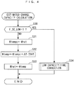
- This process is for controlling the generated voltage of the power generator 5, and is executed at a predetermined control period ⁇ T (10 msec, for example). Note that various values calculated or set in the following description are assumed to be stored in the RAM of the ECU 2.
- a low capacity flag F_SC_LOW is 1.
- the low capacity flag F_SC_LOW is set, in the charge capacity determination process described hereinafter, based on whether or not an actual charge capacity of the battery 4 is less than an estimated charge capacity What which is an estimated value of the charge capacity.
- a charging control process is executed.
- a demand voltage VACG is set at each control timing such that it is gradually increased to a predetermined charge value Vchg, and is held at the predetermined charge value Vchg after it is reached. Note that when conditions for rapidly charging the battery 4 are satisfied, at the first control timing, the demand voltage VACG is set to the predetermined charge value Vchg.
- step 7 the command signal indicative of the demand voltage VACG, which is calculated in the step 4, is output to the power generator 5, followed by terminating the present process.
- This controls the generated voltage of the power generator 5 such that it is increased to the predetermined charge value Vchg, whereby electric current is caused to flow from the power generator 5 to the battery 4, to execute charging of the battery 4.
- the process proceeds to a step 2, wherein it is determined whether or not the estimated charge capacity What is larger than the sum Wobj + WA of a predetermined target charge capacity Wobj and a predetermined value WA.
- the estimated charge capacity What is an estimated value of the charge capacity of the battery 4, and is calculated as described hereinafter.
- the predetermined target charge capacity Wobj is a target value of the estimated charge capacity What, and is set to, for example, a value which is approximately 80% of a charge level SOC (state-of-charge) of the battery 4.
- the predetermined value WA is set to a predetermined positive value close to 0.
- the process proceeds to a step 6, wherein a discharging control process is executed.
- the demand voltage VACG is set at each control timing such that it is gradually reduced to a predetermined discharge value Vdschg, and is held at the predetermined discharge value Vdschg after it is reached.
- step 7 the command signal indicative of the demand voltage VACG, which is calculated in the step 6, is output to the power generator 5, followed by terminating the present process.
- This controls the generated voltage of the power generator 5 such that it is gradually reduced to the predetermined discharge value Vdschg, and is held at the discharge value Vdschg after it is reached.
- electric current flows from the battery 4 to the auxiliary equipment 6, which places the battery 4 in the discharging state.
- step 3 it is determined whether or not the estimated charge capacity What is less than a value Wobj - WA. If the answer to this question is affirmative (YES), i.e. if What ⁇ Wobj - WA, it is determined that charging of the battery 4 should be executed, and the steps 4 and 7 are executed as described above, followed by terminating the present process.
- step 3 determines that the charge capacity of the battery 4 should be held, and the process proceeds to a step 5, wherein a hold control process is executed.
- the hold control process the demand voltage VACG is set such that the state of What ⁇ Wobj is held. By thus setting the demand voltage VACG, the estimated charge capacity What is held such that What ⁇ Wobj holds.
- the battery current IBAT is held at a value in a predetermined range (-Ia ⁇ IBAT ⁇ Ia) in the vicinity of 0.
- step 7 the command signal indicative of the demand voltage VACG, which is set in the step 5, is output to the power generator 5, followed by terminating the present process.
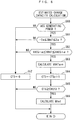
- the charge capacity determination process executed by the ECU 2 will be described with reference to FIG. 3 .
- the process is executed at the above-mentioned predetermined control period ⁇ T.
- step 10 it is determined whether or not the power generator 5 (shown as ACG in FIG. 3 ; the same shall apply hereinafter) is generating electric power. If the answer to this question is negative (NO), in steps 19 and 20, a count value CT of a discharging state counter and a count value CT2 of a charge continuation counter are both set to 0, then in a step 21, the low capacity flag F_SC_LOW is set to 0, followed by terminating the present process.
- the power generator 5 shown as ACG in FIG. 3 ; the same shall apply hereinafter
- step 10 determines whether or not the demand voltage VACG is lower than the above-mentioned predetermined discharge value Vdschg. If the answer to this question is negative (NO), the steps 19 to 21 are executed as described above, followed by terminating the present process.
- step 11 determines whether or not the battery terminal voltage VBAT is lower than a predetermined discharge reference value Vjud. If the answer to this question is negative (NO), the steps 19 to 21 are executed as described above, followed by terminating the present process.
- the process proceeds to a step 13, wherein the count value CT of the discharging state counter is set to the sum (CTz + 1) of the immediately preceding value CTz and 1. That is, the count value CT of the discharging state counter is incremented by 1.
- the discharging state counter is for counting time during which the battery terminal voltage VBAT is held below the predetermined discharge reference value Vjud during execution of the above-described discharging control process.
- step 14 it is determined whether or not the count value CT of the discharging state counter is larger than a predetermined value CREF1. If the answer to this question is negative (NO), the steps 19 to 21 are executed as described above, followed by terminating the present process.
- the process proceeds to a step 15, and it is determined whether or not the battery current IBAT is larger than 0. If the answer to this question is negative (NO), i.e. if the battery 4 is not in the charging state, it is determined that the actual charge capacity of the battery 4 is in a state close to the estimated charge capacity What, and the steps 19 to 21 are executed as described above, followed by terminating the present process.
- the process proceeds to a step 16, wherein the count value CT2 of the charge continuation counter is set to the sum (CT2z + 1) of the immediately preceding value CT2z and 1. That is, the count value CT2 of the charge continuation counter is incremented by 1.
- the charge continuation counter is for counting time during which the battery 4 is held in the charging state during execution of the above-mentioned discharging control process.
- step 17 it is determined whether or not the count value CT2 of the charge continuation counter is larger than a predetermined value CREF2. If the answer to this question is negative (NO), the step 21 is executed as described above, followed by terminating the present process.
- step 17 if the answer to the question of the step 17 is affirmative (YES), i.e. if the time during which the battery 4 is held in the charging state has reached a value ⁇ T ⁇ CREF2, it is determined that the actual charge capacity of the battery 4 is less than the estimated charge capacity What, so that the process proceeds to a step 18, wherein to indicate the fact, the low capacity flag F_SC_LOW is set to 1, followed by terminating the present process.
- the charge capacity determination process in a case where What > Wobj + WA holds in the power generation control process described with reference to FIG. 2 , and the demand voltage VACG is held at the predetermined discharge value Vdschg by execution of the discharging control process, if the battery 4 is in the charging state, it is determined that the actual charge capacity of the battery 4 is less than the estimated charge capacity What, and the low capacity flag F_SC_LOW is set to 1 to indicate the result of the determination.
- This process calculates the above-mentioned estimated charge capacity What, and is executed at the above-mentioned predetermined control period ⁇ T. Note that in the present embodiment, the estimated charge capacity What corresponds to a charge capacity parameter.
- step 30 it is determined whether or not the low capacity flag F_SC_LOW is 1. If the answer to this question is negative (NO), the process proceeds to a step 31, wherein the immediately preceding value Wtempz of a temporary value Wtemp of the estimated charge capacity is set to the estimated charge capacity What stored in the RAM.
- the process proceeds to a step 32, wherein the temporary value Wtemp of the estimated charge capacity is set to the sum (Wtempz + ⁇ T ⁇ IBAT) of the immediately preceding value Wtempz and a value ⁇ T ⁇ IBAT.
- the estimated charge capacity What is set to the temporary value Wtemp followed by terminating the present process.
- the process proceeds to a step 34, wherein a low capacity-time correction process is executed.
- the low capacity-time correction process is for correcting the estimated charge capacity What such that it becomes closer to the actual charge capacity of the battery 4, and is executed as shown FIG. 5 .
- a step 40 it is determined whether or not the immediately preceding value F_SC_LOWz of the low capacity flag is 1. If the answer to this question is negative (NO), i.e. if the present control timing is a first execution of the low capacity-time correction process, the process proceeds to a step 41, wherein a reference value Wjud is set to the sum (What + WD) of the estimated charge capacity What stored in the RAM and a predetermined correction term WD.
- the predetermined correction term WD is set to a relatively small positive predetermined value.
- step 42 the immediately preceding value Wtempz of the temporary value of the estimated charge capacity is set to the estimated charge capacity What stored in the RAM.
- step 40 determines whether the answer to the question of the step 40 is affirmative (YES), i.e. if the present control timing is a second or later execution of the low capacity-time correction process. If the answer to the question of the step 40 is affirmative (YES), i.e. if the present control timing is a second or later execution of the low capacity-time correction process, the process proceeds to a step 43, wherein the immediately preceding value Wtempz of the temporary value of the estimated charge capacity is set to the temporary value Wtemp of the estimated charge capacity, which is stored in the RAM.
- the temporary value Wtemp of the estimated charge capacity is set to the sum (Wtempz + ⁇ T ⁇ IBAt) of the immediately preceding value Wtempz and the value ⁇ T ⁇ IBAT.
- step 45 it is determined whether or not the temporary value Wtemp of the estimated charge capacity is larger than the reference value Wjud. If the answer to this question is negative (NO), the present process is immediately terminated.
- step 45 the process proceeds to a step 46, wherein the estimated charge capacity What is set to a value (Wtemp - WD) which is calculated by subtracting the correction term WD from the temporary value Wtemp.
- step 47 since the correction of the estimated charge capacity What is finished, it is judged that the low capacity-time correction process and the above-described charging control process should be finished and to indicate the fact, the low capacity flag F_SC_LOW is set to 0, followed by terminating the present process.
- the estimated charge capacity calculation process shown in FIG. 4 terminates.
- the discharging control process is started, whereafter the demand voltage VACG is gradually reduced to the predetermined discharge value Vdschg, and in accordance therewith, the battery current IBAT is also reduced.
- the demand voltage VACG reaches the predetermined discharge value Vdschg, whereafter the demand voltage VACG is held at the predetermined discharge value Vdschg.
- the discharging control process is executed when What > Wobj + WA holds, if the estimated charge capacity What is equal to or larger than the actual charge capacity of the battery 4, then the battery 4 is controlled to be in the discharging state. In spite of this control, if the battery 4 remains in the charging state, it can be estimated that the actual charge capacity of the battery 4 is less than the estimated charge capacity What at the time. Thus, it is possible to accurately estimate that the actual charge capacity of the battery 4 is less than the estimated charge capacity What. Especially, even if the estimated charge capacity What has a calculation error (deviation) which is significantly larger than the actual charge capacity of the battery 4 due to replacement of the battery 4 or the like, it is possible to accurately estimate such an occurrence of the calculation error.
- the estimated charge capacity What has a calculation error (deviation) which is significantly larger than the actual charge capacity of the battery 4 due to replacement of the battery 4 or the like, it is possible to accurately estimate such an occurrence of the calculation error.
- the charge capacity determination process in FIG. 2 is executed only during execution of the discharging control process, i.e. when What > Wobj + WA holds, but is not executed when What ⁇ Wobj + WA holds. This makes it possible to estimate that the actual charge capacity of the battery 4 is less than the estimated charge capacity What while reducing the range of change in the actual charge capacity of the battery 4.
- the charging control process is executed and the low capacity-time correction process of FIG. 5 is executed as well.
- the charging control process is executed such that the actual charge capacity of the battery 4 is increased by the correction term WD, and at the time point when the charging control process is terminated (at the time point when the answer to the question of the step 45 is affirmative (YES)), the estimated charge capacity What is corrected such that it is reduced by the correction term WD.
- YES the time point when the charging control process is terminated
- the charge capacity determination process in FIG. 3 and the low capacity-time correction process in FIG. 5 are executed repeatedly, whereby the estimated charge capacity What can be gradually made closer to the actual charge capacity of the battery 4 each time by the correction term WD, which makes it possible to improve the calculation accuracy.
- the estimated charge capacity What has a calculation error significantly larger than the actual charge capacity of the battery 4 due to replacement of the battery 4 or the like, it is possible to gradually reduce such a calculation error with the progress of control.
- the correction process of FIG. 5 as the low capacity-time correction process in the step 34 in FIG. 4 described above may be replaced by a correction process shown in FIG. 7 .
- the correction process in FIG. 7 is identical to the correction process in FIG. 5 except steps 51, 52 and 56, and hence the following description is given mainly of different points, and description of the other points will be omitted.
- the reference value Wjud is set to the estimated charge capacity What stored in the RAM.
- the immediately preceding value Wtempz of the temporary value of the estimated charge capacity is set to a value (What - WD) which is calculated by subtracting the correction term WD from the estimated charge capacity What stored in the RAM.
- step 55 the process proceeds to the step 56, wherein the estimated charge capacity What is set to the temporary value Wtemp.
- step 57 similarly to the above-mentioned step 47, the low capacity flag F_SC_LOW is set to 0, followed by terminating the present process.
- the low capacity-time correction process in FIG. 7 is executed as described above, it is possible to obtain the same advantageous effects as obtained in the case where the low capacity-time correction process in FIG. 5 is executed. More specifically, when the actual charge capacity of the battery 4 is estimated to be less than the estimated charge capacity What, it is possible to make the estimated charge capacity What closer to the actual charge capacity of the battery 4 by the correction term WD.
- the battery 4 of lead-acid type is used as the electric storage device
- the electric storage device according to the present invention is not limited to this, but any device may be used insofar as it can charge and discharge.
- a rechargeable battery, a super capacitor, or the like, which can charge and discharge may be used as the electric storage device.
- the estimated charge capacity What is used as a charge capacity parameter is not limited to this, but any parameter may be used insofar as it indicates a charge capacity of the electric storage device.
- a value which is calculated by subtracting the estimated charge capacity What from the maximum charge capacity of the electric storage device as a chargeable limit may be used as the charge capacity parameter.
- the charge level SOC or a value which is calculated by subtracting the charge level SOC from a value 100 may be used as the charge capacity parameter. In this case, it is only required that the charge level SOC is calculated based on the estimated charge capacity What.
- the ECU 2 is used as a control device
- the control device of the present invention is not limited to this, but any device may be used insofar as it can control charging and discharging operations of the electric storage device.
- a control circuit may be used as the control device.
- the power generator 5 of alternating current type is used as the power generator
- the power generator of the present invention is not limited to this, but any generator may be used insofar as the generated voltage thereof can be controlled.
- a power generator of direct current type may be used as the power generator.
- the auxiliary equipment 6 mounted on a vehicle is used as an electric device
- the electric device of the present invention is not limited to this, but any device may be used insofar as it works by power supply.
- a device incorporating an electric motor or an electromagnetic actuator may be used as the electric device.
- the sensor unit 3 is used as charging/discharging state detection means
- the charging/discharging state detection means of the present invention is not limited to this, but any charging/discharging state detection means may be used insofar as it can detect a charging/discharging state.
- an electric current sensor which detects electric current may be used as the charging/discharging state detection means.
- the charge capacity parameter estimation system of the present embodiment is identical in respect of the mechanical and electrical arrangement to the charge capacity parameter estimation system according to the first embodiment, and only details of the control processes are different. Therefore, the following description is mainly given of different points. Further, the same components as those of the first embodiment are denoted by the same reference numerals and description thereof is omitted.
- the charge capacity parameter estimation system comprises a ECU 2, and the ECU 2 executes, as the power generation control process, a control process is executed which is obtained by omitting the step 1 from the above-described power generation control process in FIG. 2 , but the above-described charge capacity determination process in FIG. 3 is not executed. Further, the ECU 2 executes, as the estimated charge capacity calculation process, a calculation process shown in FIG. 8 is executed at the above-mentioned predetermined control period ⁇ T instead of the above-described calculation process in FIG. 4 .
- a step 60 it is determined whether or not the power generator 5 is generating electric power. If the answer to this question is negative (NO), the process proceeds to a step 67, wherein a count value CT3 of a calculation condition counter is set to 0, followed by terminating the present process. On the other hand, if answer to the question of the step 60 is affirmative (YES), the process proceeds to a step 61, wherein it is determined whether or not -Ia ⁇ IBAT ⁇ Ia holds. If the answer to this question is negative (NO), the step 67 is executed as described above, followed by terminating the present process.
- step 61 determines whether or not VACG - ⁇ ⁇ VBAT ⁇ VACG + ⁇ holds.
- the value ⁇ is a positive predetermined value, and the step 62 is for determining whether or not load of auxiliary equipment 6 is in an unstable state (suddenly decreasing or suddenly increasing state).
- step 67 is executed, followed by terminating the present process.
- the answer to the question of the step 62 is negative (NO)
- the step 67 is executed, followed by terminating the present process.
- the answer to the question of the step 62 is affirmative (YES)
- the process proceeds to a step 63, wherein an average value VBATave of an battery terminal voltage is calculated.
- the average value VBATave is calculated by the moving average method using a predetermined number of values of the battery terminal voltage VBAT.
- the count value CT3 of the calculation condition counter is set to the sum (CT3z + 1) of the immediately preceding value CT3z thereof and 1. That is, the count value CT3 of the calculation condition counter is incremented by 1.
- the calculation condition counter is for counting a duration of time during which the calculation conditions of the estimated charge capacity What are satisfied (duration of time during which all of the answers to the questions of the above-described steps 60 to 62 are affirmative (YES)).
- step 65 it is determined whether or not the count value CT3 of the calculation condition counter is larger than a predetermined value CREF3. If the answer to this question is negative (NO), the present process is immediately terminated.
- step 65 determines whether the answer to the question of the step 65 is affirmative (YES), i.e. if the duration of time during which the calculation conditions of the estimated charge capacity What are satisfied has reached a value ⁇ T ⁇ CREF3, the process proceeds to a step 66, wherein the estimated charge capacity What is calculated according to the average value VBATave of the battery terminal voltage and the battery temperature TB, by searching a map shown in FIG. 9 .
- i and j are positive integers.
- the estimated charge capacity What is calculated in the step 66, followed by terminating the present process.
- the ECU2 corresponds to the control device and the estimation means
- the sensor unit 3 corresponds to an electric current detecting-means and voltage detecting-means.
- the battery current IBAT corresponds to electric current which flows during charging and discharging operations of the electric storage device
- the battery terminal voltage VBAT and the average value VBATave of the battery terminal voltage correspond to a voltage of the electric storage device.
- the map of FIG. 9 corresponds to a correlation model which represents a correlation between the voltage of the electric storage device and the charge capacity parameter, and the estimated charge capacity What corresponds to the charge capacity parameter.
- the charge capacity parameter estimation system when the battery current IBAT is held in a predetermined range (-Ia ⁇ IBAT ⁇ Ia) close to 0 by the power generation control process, the average value VBATave of the battery terminal voltage is calculated, and when the time during which the battery current IBAT is held close to 0 has continued for ⁇ T ⁇ CREF3, the estimated charge capacity What is calculated according to the average value VBATave of the battery terminal voltage and the battery temperature TB, by searching the map shown in FIG. 9 .
- the battery terminal voltage VBAT at the time of the battery current IBAT being held close to 0 can be regarded as close to an open circuit voltage of the battery 4, and hence, by using such average value VBATave of the battery terminal voltage VBAT, it is possible to accurately calculate the estimated charge capacity What even during power generation of the power generator 5.
- the correlation model is not limited to this, but any correlation model may be used insofar as it can represent the correlation between the voltage of the electric storage device and the charge capacity parameter.
- the correlation model a mathematical formula which defines a relationship between the voltage of the electric storage device and the charge capacity parameter may be used, or a combination of the mathematical formula and the map may be used.
- a charge capacity parameter estimation system for an electric storage device capable of charging and discharging is provided, which can accurately estimate a charge capacity parameter indicative of a charge capacity of the electric storage device.
- the charge capacity parameter estimation system for a battery includes an ECU and a sensor unit.
- the ECU estimates that an actual charge capacity of the electric storage device is less than an estimated charge capacity, when a charging state of the electric storage device is detected, in a case where a generated voltage of a power generator is controlled such that the battery executes a discharging operation to an auxiliary equipment.
Claims (2)
- Ladekapazitätparameter-Schätzsystem, das dazu ausgelegt ist, einen Ladekapazitätsparameter (What) zu schätzen, der eine Ladekapazität einer elektrischen Speichervorrichtung (4) angibt, die elektrisch verbunden ist mit einem Stromgenerator (5), dessen generierte Spannung durch eine Steuerungsvorrichtung (2) gesteuert wird, und mit einer elektrischen Vorrichtung (6), der die vom Stromgenerator (5) generierte Spannung zugeführt wird, wobei die elektrische Speichervorrichtung (4) ausgelegt ist, um in Bezug auf einen Ladebetrieb von dem Stromgenerator (5) und einen Entladebetrieb zur elektrischen Vorrichtung (6) gemäß dem Ladekapazitätsparameter (What), der die Ladekapazität angibt, durch Steuerung der vom Stromgenerator (5) generierten Spannung durch die Steuerungsvorrichtung (2) gesteuert zu werden,
wobei das System ein Stromdetektionsmittel (3) zum Detektieren eines Stroms, der während eines Lade-/Entladebetriebs der elektrischen Speichervorrichtung (4) fließt; und
ein Spannungsdetektionsmittel (3) zum Detektieren einer Spannung der elektrischen Speichervorrichtung (3),
gekennzeichnet durch
ein Schätzmittel, das ausgelegt ist, um zu schätzen, dass eine aktuelle Ladekapazität der elektrischen Speichervorrichtung (4) niedriger als die vom geschätzten Ladekapazitätsparameter (What) angegebene Ladekapazität ist, wenn der Ladezustand der elektrischen Speichervorrichtung (4), in der ein zur elektrischen Speichervorrichtung (4) fließender elektrischer Strom größer als 0 ist, detektiert wird, in einem Fall, wo die vom Stromgenerator (5) generierte Spannung auf einen vorbestimmten Entladewert (Vdschg) gesteuert wird, so dass die elektrische Speichervorrichtung (4) den Entladebetrieb zur elektrischen Vorrichtung (6) ausführt, wobei der Ladekapazitätsparameter (What) unter Verwendung eines Korrelationsmodells geschätzt wird, das eine Korrelation zwischen der Spannung der elektrischen Speichervorrichtung (4) und dem Ladekapazitätsparameter (What) repräsentiert, basierend auf einer Spannung der elektrischen Speichervorrichtung (4), die detektiert wird, wenn der zu oder von der elektrischen Speichervorrichtung (4) fließende elektrische Strom in einem vorbestimmten Bereich um 0 herum erhalten wird, durch die vom Stromgenerator (5) generierte Spannung, und
ein Korrekturmittel, das dazu ausgelegt ist, um basierend auf dem vom Schätzmittel bestimmten Ergebnis, den geschätzten Ladekapazitätsparameter (What) wiederholt zu korrigieren, so dass er der aktuellen Kapazität der elektrischen Speichervorrichtung (4) allmählich näher kommt,
wobei die elektrische Speichervorrichtung (4) eine wiederaufladbare Batterie oder ein Superkondensator ist. - Das Ladekapazitätparameter-Schätzsystem nach Anspruch 1,
wobei, wenn das Schätzmittel schätzt, dass die aktuelle Ladekapazität der elektrischen Speichervorrichtung (4) niedriger als die vom Ladekapazitätsparameter (What) angegebene Ladekapazität ist, die Steuervorrichtung ausgelegt ist, um eine Ladesteuerung zum Steuern der vom Stromgenerator (5) generierten Spannung auszuführen, so dass die vom Ladekapazitätsparameter (What) angegebene Ladekapazität durch den Ladebetrieb der elektrischen Speichervorrichtung (4) allmählich erhöht wird, und um die Ladesteuerung zu einer Zeit zu beenden, zu der die vom Ladekapazitätsparamter (What) angegebene Ladekapazität auf einen vorbestimmten Wert (WD) ab einem Beginn der Ladesteuerung, während deren Ausführung, erhöht wird, und
wobei, wenn die Ladesteuerung beendet wird, das Korrekturmittel ausgelegt ist, um den geschätzten Ladekapazitätsparameter (What) um den vorbestimmten Wert (WD) derart zu korrigieren, dass sich die vom Ladekapazitätsparameter (What) angegebene Ladekapazität der aktuellen Ladekapazität der elektrischen Speichervorrichtung (4) annähert.
Applications Claiming Priority (1)
| Application Number | Priority Date | Filing Date | Title |
|---|---|---|---|
| JP2011233560A JP5487183B2 (ja) | 2011-10-25 | 2011-10-25 | 蓄電装置の充電容量パラメータ推定装置 |
Publications (3)
| Publication Number | Publication Date |
|---|---|
| EP2587622A2 EP2587622A2 (de) | 2013-05-01 |
| EP2587622A3 EP2587622A3 (de) | 2013-08-28 |
| EP2587622B1 true EP2587622B1 (de) | 2017-07-12 |
Family
ID=47137481
Family Applications (1)
| Application Number | Title | Priority Date | Filing Date |
|---|---|---|---|
| EP12181401.6A Not-in-force EP2587622B1 (de) | 2011-10-25 | 2012-08-22 | Ladekapazitätsparameter-Bewertungssystem einer elektrischen Speichervorrichtung |
Country Status (3)
| Country | Link |
|---|---|
| US (1) | US8994324B2 (de) |
| EP (1) | EP2587622B1 (de) |
| JP (1) | JP5487183B2 (de) |
Families Citing this family (3)
| Publication number | Priority date | Publication date | Assignee | Title |
|---|---|---|---|---|
| JP6747062B2 (ja) * | 2016-05-31 | 2020-08-26 | 株式会社デンソー | 制御装置 |
| US10148101B2 (en) * | 2016-08-12 | 2018-12-04 | Mediatek Inc. | Battery charging system and battery charging protection control method |
| TWI809941B (zh) * | 2022-06-21 | 2023-07-21 | 加百裕工業股份有限公司 | 電池容量受放電前環境低溫影響的計算方法 |
Family Cites Families (10)
| Publication number | Priority date | Publication date | Assignee | Title |
|---|---|---|---|---|
| JPH08339835A (ja) | 1995-06-12 | 1996-12-24 | Isuzu Motors Ltd | 電池残存容量測定装置および方法 |
| JPH09308113A (ja) * | 1996-05-13 | 1997-11-28 | Matsushita Electric Ind Co Ltd | 二次電池の容量演算表示装置 |
| DE19643012B4 (de) * | 1996-10-18 | 2008-01-03 | Vb Autobatterie Gmbh & Co. Kgaa | Verfahren zur Ladung eines elektrischen Akkumulators mit einem Generator |
| JP4731051B2 (ja) * | 2001-06-20 | 2011-07-20 | 株式会社日本自動車部品総合研究所 | 鉛蓄電池の容量検出方法 |
| JP4078847B2 (ja) * | 2002-02-21 | 2008-04-23 | トヨタ自動車株式会社 | 残存容量算出装置および残存容量算出方法 |
| US7317300B2 (en) * | 2003-06-23 | 2008-01-08 | Denso Corporation | Automotive battery state monitor apparatus |
| DE102004023621A1 (de) * | 2004-05-10 | 2005-12-01 | Volkswagen Ag | Verfahren und Vorrichtung zur Energieinhaltsbestimmung eines Energiespeichers |
| JP2006333553A (ja) * | 2005-05-23 | 2006-12-07 | Fujitsu Ten Ltd | バッテリ充電状態算出システム、バッテリ充電状態算出方法、及びバッテリ監視装置 |
| US8026698B2 (en) * | 2006-02-09 | 2011-09-27 | Scheucher Karl F | Scalable intelligent power supply system and method |
| JP2012186950A (ja) * | 2011-03-07 | 2012-09-27 | Denso Corp | 電力供給システム |
-
2011
- 2011-10-25 JP JP2011233560A patent/JP5487183B2/ja not_active Expired - Fee Related
-
2012
- 2012-08-22 EP EP12181401.6A patent/EP2587622B1/de not_active Not-in-force
- 2012-09-11 US US13/610,001 patent/US8994324B2/en active Active
Non-Patent Citations (1)
| Title |
|---|
| None * |
Also Published As
| Publication number | Publication date |
|---|---|
| JP2013093942A (ja) | 2013-05-16 |
| US8994324B2 (en) | 2015-03-31 |
| US20130099727A1 (en) | 2013-04-25 |
| EP2587622A3 (de) | 2013-08-28 |
| JP5487183B2 (ja) | 2014-05-07 |
| EP2587622A2 (de) | 2013-05-01 |
Similar Documents
| Publication | Publication Date | Title |
|---|---|---|
| KR101589155B1 (ko) | 전기 저장 시스템 | |
| US10601230B2 (en) | Electric power supply system for vehicle | |
| US10838011B2 (en) | Method for estimating state of charge and on-vehicle battery system | |
| KR101245788B1 (ko) | 배터리의 작동점 제어 방법 및 장치 | |
| US9475480B2 (en) | Battery charge/discharge control device and hybrid vehicle using the same | |
| EP1674877B1 (de) | Vorrichtung und verfahren zur berechnung der restkapazität einer sekundärbatterie | |
| US10090686B2 (en) | Electrical storage system | |
| US9428177B2 (en) | Vehicle | |
| US20160049821A1 (en) | Electrical storage system, and full charge capacity estimation method for electrical storage device | |
| US8912761B2 (en) | Upper-limit of state-of-charge estimating device and upper-limit of state-of-charge estimating method | |
| JP5673654B2 (ja) | 蓄電システムおよび満充電容量算出方法 | |
| US7750640B2 (en) | Electromotive force computing device and state of charge estimating device | |
| US8000915B2 (en) | Method for estimating state of charge of a rechargeable battery | |
| EP2847026B1 (de) | Elektrisches speichersystem und entzerrungsverfahren dafür | |
| CN108885242B (zh) | 二次电池劣化估计装置和二次电池劣化估计方法 | |
| JP4959511B2 (ja) | 蓄電池用充電制御装置 | |
| KR20020036851A (ko) | 배터리용량계측 및 잔존용량 산출장치 | |
| JP2008064496A (ja) | 電池制御装置、電動車両、及び二次電池の充電状態を推定するための処理をコンピュータに実行させるためのプログラム | |
| WO2015025212A1 (en) | Electric storage system and full charge capacity estimation method for electric storage device | |
| JP2010019595A (ja) | 蓄電デバイスの残存容量演算装置 | |
| EP2587622B1 (de) | Ladekapazitätsparameter-Bewertungssystem einer elektrischen Speichervorrichtung | |
| CN115864559A (zh) | 电池的充电方法 | |
| JP3475894B2 (ja) | 車両用二次電池の満充電判定装置及び残存容量算出装置 | |
| JP2020061823A (ja) | 二次電池制御装置 | |
| JP2014155401A (ja) | 蓄電システム |
Legal Events
| Date | Code | Title | Description |
|---|---|---|---|
| PUAI | Public reference made under article 153(3) epc to a published international application that has entered the european phase |
Free format text: ORIGINAL CODE: 0009012 |
|
| 17P | Request for examination filed |
Effective date: 20120822 |
|
| AK | Designated contracting states |
Kind code of ref document: A2 Designated state(s): AL AT BE BG CH CY CZ DE DK EE ES FI FR GB GR HR HU IE IS IT LI LT LU LV MC MK MT NL NO PL PT RO RS SE SI SK SM TR |
|
| AX | Request for extension of the european patent |
Extension state: BA ME |
|
| PUAL | Search report despatched |
Free format text: ORIGINAL CODE: 0009013 |
|
| AK | Designated contracting states |
Kind code of ref document: A3 Designated state(s): AL AT BE BG CH CY CZ DE DK EE ES FI FR GB GR HR HU IE IS IT LI LT LU LV MC MK MT NL NO PL PT RO RS SE SI SK SM TR |
|
| AX | Request for extension of the european patent |
Extension state: BA ME |
|
| RIC1 | Information provided on ipc code assigned before grant |
Ipc: H02J 7/04 20060101AFI20130722BHEP Ipc: H02J 7/14 20060101ALI20130722BHEP Ipc: G01R 31/36 20060101ALI20130722BHEP |
|
| 17Q | First examination report despatched |
Effective date: 20151109 |
|
| GRAP | Despatch of communication of intention to grant a patent |
Free format text: ORIGINAL CODE: EPIDOSNIGR1 |
|
| STAA | Information on the status of an ep patent application or granted ep patent |
Free format text: STATUS: GRANT OF PATENT IS INTENDED |
|
| INTG | Intention to grant announced |
Effective date: 20170208 |
|
| GRAS | Grant fee paid |
Free format text: ORIGINAL CODE: EPIDOSNIGR3 |
|
| GRAA | (expected) grant |
Free format text: ORIGINAL CODE: 0009210 |
|
| STAA | Information on the status of an ep patent application or granted ep patent |
Free format text: STATUS: THE PATENT HAS BEEN GRANTED |
|
| AK | Designated contracting states |
Kind code of ref document: B1 Designated state(s): AL AT BE BG CH CY CZ DE DK EE ES FI FR GB GR HR HU IE IS IT LI LT LU LV MC MK MT NL NO PL PT RO RS SE SI SK SM TR |
|
| REG | Reference to a national code |
Ref country code: GB Ref legal event code: FG4D |
|
| REG | Reference to a national code |
Ref country code: CH Ref legal event code: EP |
|
| REG | Reference to a national code |
Ref country code: AT Ref legal event code: REF Ref document number: 909177 Country of ref document: AT Kind code of ref document: T Effective date: 20170715 |
|
| REG | Reference to a national code |
Ref country code: IE Ref legal event code: FG4D |
|
| REG | Reference to a national code |
Ref country code: FR Ref legal event code: PLFP Year of fee payment: 6 |
|
| REG | Reference to a national code |
Ref country code: DE Ref legal event code: R096 Ref document number: 602012034359 Country of ref document: DE |
|
| REG | Reference to a national code |
Ref country code: NL Ref legal event code: MP Effective date: 20170712 |
|
| REG | Reference to a national code |
Ref country code: LT Ref legal event code: MG4D |
|
| REG | Reference to a national code |
Ref country code: AT Ref legal event code: MK05 Ref document number: 909177 Country of ref document: AT Kind code of ref document: T Effective date: 20170712 |
|
| PG25 | Lapsed in a contracting state [announced via postgrant information from national office to epo] |
Ref country code: AT Free format text: LAPSE BECAUSE OF FAILURE TO SUBMIT A TRANSLATION OF THE DESCRIPTION OR TO PAY THE FEE WITHIN THE PRESCRIBED TIME-LIMIT Effective date: 20170712 Ref country code: FI Free format text: LAPSE BECAUSE OF FAILURE TO SUBMIT A TRANSLATION OF THE DESCRIPTION OR TO PAY THE FEE WITHIN THE PRESCRIBED TIME-LIMIT Effective date: 20170712 Ref country code: HR Free format text: LAPSE BECAUSE OF FAILURE TO SUBMIT A TRANSLATION OF THE DESCRIPTION OR TO PAY THE FEE WITHIN THE PRESCRIBED TIME-LIMIT Effective date: 20170712 Ref country code: LT Free format text: LAPSE BECAUSE OF FAILURE TO SUBMIT A TRANSLATION OF THE DESCRIPTION OR TO PAY THE FEE WITHIN THE PRESCRIBED TIME-LIMIT Effective date: 20170712 Ref country code: NO Free format text: LAPSE BECAUSE OF FAILURE TO SUBMIT A TRANSLATION OF THE DESCRIPTION OR TO PAY THE FEE WITHIN THE PRESCRIBED TIME-LIMIT Effective date: 20171012 Ref country code: SE Free format text: LAPSE BECAUSE OF FAILURE TO SUBMIT A TRANSLATION OF THE DESCRIPTION OR TO PAY THE FEE WITHIN THE PRESCRIBED TIME-LIMIT Effective date: 20170712 Ref country code: NL Free format text: LAPSE BECAUSE OF FAILURE TO SUBMIT A TRANSLATION OF THE DESCRIPTION OR TO PAY THE FEE WITHIN THE PRESCRIBED TIME-LIMIT Effective date: 20170712 |
|
| PG25 | Lapsed in a contracting state [announced via postgrant information from national office to epo] |
Ref country code: IS Free format text: LAPSE BECAUSE OF FAILURE TO SUBMIT A TRANSLATION OF THE DESCRIPTION OR TO PAY THE FEE WITHIN THE PRESCRIBED TIME-LIMIT Effective date: 20171112 Ref country code: LV Free format text: LAPSE BECAUSE OF FAILURE TO SUBMIT A TRANSLATION OF THE DESCRIPTION OR TO PAY THE FEE WITHIN THE PRESCRIBED TIME-LIMIT Effective date: 20170712 Ref country code: PL Free format text: LAPSE BECAUSE OF FAILURE TO SUBMIT A TRANSLATION OF THE DESCRIPTION OR TO PAY THE FEE WITHIN THE PRESCRIBED TIME-LIMIT Effective date: 20170712 Ref country code: ES Free format text: LAPSE BECAUSE OF FAILURE TO SUBMIT A TRANSLATION OF THE DESCRIPTION OR TO PAY THE FEE WITHIN THE PRESCRIBED TIME-LIMIT Effective date: 20170712 Ref country code: GR Free format text: LAPSE BECAUSE OF FAILURE TO SUBMIT A TRANSLATION OF THE DESCRIPTION OR TO PAY THE FEE WITHIN THE PRESCRIBED TIME-LIMIT Effective date: 20171013 Ref country code: BG Free format text: LAPSE BECAUSE OF FAILURE TO SUBMIT A TRANSLATION OF THE DESCRIPTION OR TO PAY THE FEE WITHIN THE PRESCRIBED TIME-LIMIT Effective date: 20171012 Ref country code: RS Free format text: LAPSE BECAUSE OF FAILURE TO SUBMIT A TRANSLATION OF THE DESCRIPTION OR TO PAY THE FEE WITHIN THE PRESCRIBED TIME-LIMIT Effective date: 20170712 |
|
| REG | Reference to a national code |
Ref country code: CH Ref legal event code: PL |
|
| REG | Reference to a national code |
Ref country code: DE Ref legal event code: R097 Ref document number: 602012034359 Country of ref document: DE |
|
| PG25 | Lapsed in a contracting state [announced via postgrant information from national office to epo] |
Ref country code: MC Free format text: LAPSE BECAUSE OF FAILURE TO SUBMIT A TRANSLATION OF THE DESCRIPTION OR TO PAY THE FEE WITHIN THE PRESCRIBED TIME-LIMIT Effective date: 20170712 Ref country code: CH Free format text: LAPSE BECAUSE OF NON-PAYMENT OF DUE FEES Effective date: 20170831 Ref country code: LI Free format text: LAPSE BECAUSE OF NON-PAYMENT OF DUE FEES Effective date: 20170831 Ref country code: DK Free format text: LAPSE BECAUSE OF FAILURE TO SUBMIT A TRANSLATION OF THE DESCRIPTION OR TO PAY THE FEE WITHIN THE PRESCRIBED TIME-LIMIT Effective date: 20170712 Ref country code: CZ Free format text: LAPSE BECAUSE OF FAILURE TO SUBMIT A TRANSLATION OF THE DESCRIPTION OR TO PAY THE FEE WITHIN THE PRESCRIBED TIME-LIMIT Effective date: 20170712 Ref country code: RO Free format text: LAPSE BECAUSE OF FAILURE TO SUBMIT A TRANSLATION OF THE DESCRIPTION OR TO PAY THE FEE WITHIN THE PRESCRIBED TIME-LIMIT Effective date: 20170712 |
|
| PLBE | No opposition filed within time limit |
Free format text: ORIGINAL CODE: 0009261 |
|
| STAA | Information on the status of an ep patent application or granted ep patent |
Free format text: STATUS: NO OPPOSITION FILED WITHIN TIME LIMIT |
|
| REG | Reference to a national code |
Ref country code: IE Ref legal event code: MM4A |
|
| PG25 | Lapsed in a contracting state [announced via postgrant information from national office to epo] |
Ref country code: SK Free format text: LAPSE BECAUSE OF FAILURE TO SUBMIT A TRANSLATION OF THE DESCRIPTION OR TO PAY THE FEE WITHIN THE PRESCRIBED TIME-LIMIT Effective date: 20170712 Ref country code: EE Free format text: LAPSE BECAUSE OF FAILURE TO SUBMIT A TRANSLATION OF THE DESCRIPTION OR TO PAY THE FEE WITHIN THE PRESCRIBED TIME-LIMIT Effective date: 20170712 Ref country code: SM Free format text: LAPSE BECAUSE OF FAILURE TO SUBMIT A TRANSLATION OF THE DESCRIPTION OR TO PAY THE FEE WITHIN THE PRESCRIBED TIME-LIMIT Effective date: 20170712 Ref country code: IT Free format text: LAPSE BECAUSE OF FAILURE TO SUBMIT A TRANSLATION OF THE DESCRIPTION OR TO PAY THE FEE WITHIN THE PRESCRIBED TIME-LIMIT Effective date: 20170712 |
|
| REG | Reference to a national code |
Ref country code: BE Ref legal event code: MM Effective date: 20170831 |
|
| 26N | No opposition filed |
Effective date: 20180413 |
|
| PG25 | Lapsed in a contracting state [announced via postgrant information from national office to epo] |
Ref country code: LU Free format text: LAPSE BECAUSE OF NON-PAYMENT OF DUE FEES Effective date: 20170822 |
|
| PG25 | Lapsed in a contracting state [announced via postgrant information from national office to epo] |
Ref country code: IE Free format text: LAPSE BECAUSE OF NON-PAYMENT OF DUE FEES Effective date: 20170822 |
|
| REG | Reference to a national code |
Ref country code: FR Ref legal event code: PLFP Year of fee payment: 7 |
|
| PG25 | Lapsed in a contracting state [announced via postgrant information from national office to epo] |
Ref country code: SI Free format text: LAPSE BECAUSE OF FAILURE TO SUBMIT A TRANSLATION OF THE DESCRIPTION OR TO PAY THE FEE WITHIN THE PRESCRIBED TIME-LIMIT Effective date: 20170712 Ref country code: BE Free format text: LAPSE BECAUSE OF NON-PAYMENT OF DUE FEES Effective date: 20170831 |
|
| PG25 | Lapsed in a contracting state [announced via postgrant information from national office to epo] |
Ref country code: MT Free format text: LAPSE BECAUSE OF NON-PAYMENT OF DUE FEES Effective date: 20170822 |
|
| PG25 | Lapsed in a contracting state [announced via postgrant information from national office to epo] |
Ref country code: HU Free format text: LAPSE BECAUSE OF FAILURE TO SUBMIT A TRANSLATION OF THE DESCRIPTION OR TO PAY THE FEE WITHIN THE PRESCRIBED TIME-LIMIT; INVALID AB INITIO Effective date: 20120822 |
|
| PG25 | Lapsed in a contracting state [announced via postgrant information from national office to epo] |
Ref country code: CY Free format text: LAPSE BECAUSE OF NON-PAYMENT OF DUE FEES Effective date: 20170712 |
|
| PG25 | Lapsed in a contracting state [announced via postgrant information from national office to epo] |
Ref country code: MK Free format text: LAPSE BECAUSE OF FAILURE TO SUBMIT A TRANSLATION OF THE DESCRIPTION OR TO PAY THE FEE WITHIN THE PRESCRIBED TIME-LIMIT Effective date: 20170712 |
|
| PG25 | Lapsed in a contracting state [announced via postgrant information from national office to epo] |
Ref country code: TR Free format text: LAPSE BECAUSE OF FAILURE TO SUBMIT A TRANSLATION OF THE DESCRIPTION OR TO PAY THE FEE WITHIN THE PRESCRIBED TIME-LIMIT Effective date: 20170712 |
|
| PG25 | Lapsed in a contracting state [announced via postgrant information from national office to epo] |
Ref country code: PT Free format text: LAPSE BECAUSE OF FAILURE TO SUBMIT A TRANSLATION OF THE DESCRIPTION OR TO PAY THE FEE WITHIN THE PRESCRIBED TIME-LIMIT Effective date: 20170712 |
|
| PG25 | Lapsed in a contracting state [announced via postgrant information from national office to epo] |
Ref country code: AL Free format text: LAPSE BECAUSE OF FAILURE TO SUBMIT A TRANSLATION OF THE DESCRIPTION OR TO PAY THE FEE WITHIN THE PRESCRIBED TIME-LIMIT Effective date: 20170712 |
|
| REG | Reference to a national code |
Ref country code: DE Ref legal event code: R084 Ref document number: 602012034359 Country of ref document: DE |
|
| REG | Reference to a national code |
Ref country code: GB Ref legal event code: 746 Effective date: 20200914 |
|
| PGFP | Annual fee paid to national office [announced via postgrant information from national office to epo] |
Ref country code: GB Payment date: 20200813 Year of fee payment: 9 Ref country code: FR Payment date: 20200715 Year of fee payment: 9 Ref country code: DE Payment date: 20200812 Year of fee payment: 9 |
|
| REG | Reference to a national code |
Ref country code: DE Ref legal event code: R119 Ref document number: 602012034359 Country of ref document: DE |
|
| GBPC | Gb: european patent ceased through non-payment of renewal fee |
Effective date: 20210822 |
|
| PG25 | Lapsed in a contracting state [announced via postgrant information from national office to epo] |
Ref country code: GB Free format text: LAPSE BECAUSE OF NON-PAYMENT OF DUE FEES Effective date: 20210822 Ref country code: FR Free format text: LAPSE BECAUSE OF NON-PAYMENT OF DUE FEES Effective date: 20210831 Ref country code: DE Free format text: LAPSE BECAUSE OF NON-PAYMENT OF DUE FEES Effective date: 20220301 |