EP2587086B1 - Braking device for a railway vehicle - Google Patents
Braking device for a railway vehicle Download PDFInfo
- Publication number
- EP2587086B1 EP2587086B1 EP20120189181 EP12189181A EP2587086B1 EP 2587086 B1 EP2587086 B1 EP 2587086B1 EP 20120189181 EP20120189181 EP 20120189181 EP 12189181 A EP12189181 A EP 12189181A EP 2587086 B1 EP2587086 B1 EP 2587086B1
- Authority
- EP
- European Patent Office
- Prior art keywords
- latch
- lining
- vertical
- slide
- brake lining
- Prior art date
- Legal status (The legal status is an assumption and is not a legal conclusion. Google has not performed a legal analysis and makes no representation as to the accuracy of the status listed.)
- Revoked
Links
Images


Classifications
-
- F—MECHANICAL ENGINEERING; LIGHTING; HEATING; WEAPONS; BLASTING
- F16—ENGINEERING ELEMENTS AND UNITS; GENERAL MEASURES FOR PRODUCING AND MAINTAINING EFFECTIVE FUNCTIONING OF MACHINES OR INSTALLATIONS; THERMAL INSULATION IN GENERAL
- F16D—COUPLINGS FOR TRANSMITTING ROTATION; CLUTCHES; BRAKES
- F16D69/00—Friction linings; Attachment thereof; Selection of coacting friction substances or surfaces
- F16D69/04—Attachment of linings
- F16D69/0408—Attachment of linings specially adapted for plane linings
-
- F—MECHANICAL ENGINEERING; LIGHTING; HEATING; WEAPONS; BLASTING
- F16—ENGINEERING ELEMENTS AND UNITS; GENERAL MEASURES FOR PRODUCING AND MAINTAINING EFFECTIVE FUNCTIONING OF MACHINES OR INSTALLATIONS; THERMAL INSULATION IN GENERAL
- F16D—COUPLINGS FOR TRANSMITTING ROTATION; CLUTCHES; BRAKES
- F16D65/00—Parts or details
- F16D65/02—Braking members; Mounting thereof
- F16D65/04—Bands, shoes or pads; Pivots or supporting members therefor
- F16D65/092—Bands, shoes or pads; Pivots or supporting members therefor for axially-engaging brakes, e.g. disc brakes
- F16D65/095—Pivots or supporting members therefor
- F16D65/097—Resilient means interposed between pads and supporting members or other brake parts
- F16D65/0971—Resilient means interposed between pads and supporting members or other brake parts transmitting brake actuation force, e.g. elements interposed between brake piston and pad
-
- F—MECHANICAL ENGINEERING; LIGHTING; HEATING; WEAPONS; BLASTING
- F16—ENGINEERING ELEMENTS AND UNITS; GENERAL MEASURES FOR PRODUCING AND MAINTAINING EFFECTIVE FUNCTIONING OF MACHINES OR INSTALLATIONS; THERMAL INSULATION IN GENERAL
- F16D—COUPLINGS FOR TRANSMITTING ROTATION; CLUTCHES; BRAKES
- F16D69/00—Friction linings; Attachment thereof; Selection of coacting friction substances or surfaces
- F16D69/04—Attachment of linings
- F16D2069/0425—Attachment methods or devices
Definitions
- the present invention relates to the field of braking of railway vehicles and, more particularly, the fixing of a brake lining on a stuffing box.
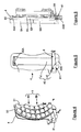
- a railway vehicle comprises a plurality of axles 11 on which brake disks 10 are fixed as shown in FIG. figure 1 .
- the railway vehicle comprises a braking device 1 comprising at least one lining 2 on which is mounted a brake lining 3.
- the lining 3 is pressed on the brake disk 10
- the friction of the lining 3 on the brake disc 10 reduces the rotational speed of the axle 11 which decreases the speed of the railway vehicle.
- the braking device 1 comprises a mechanism (not referenced), known to those skilled in the art under the designation of wheelhouse, adapted to support a brake lining 3 on each face of the brake disk 10 as shown in FIG. figure 1 .
- a brake lining 3 traditionally comprises a metal base 30 comprising, on a first face, friction pads 31 of organic material or sintered material intended to come into contact with the brake disk 10 and comprising, on a second face, a fastening foot having a dovetail shape (not shown).
- a stuffing liner 2 conventionally comprises a vertical slideway 20 of dovetail section adapted to receive the fastening foot of the lining 3.
- the slideway 20 has a lower end 20B which is open and an upper end 20A which is closed so as to allow insertion of the lining 3 from the bottom up vertically in the slide 20 of the liner 2.
- a latch 24 is put in place to retain the 3.
- the stuffing-box 2 comprises a horizontal slide 23, formed in the lower part of the stuffing-box 2, which separates the vertical slide 20 in two parts: an upper part 21 in which the packing is housed. 3 and a lower portion 22 which remains empty.
- the latch 24 is translated from left to right in the horizontal slide 23 to lock the lower end of the lining 3 (not shown on the figure 3 ), the position of the latch 24 being secured by means of pins placed at the lateral ends of the latch 24.
- the horizontal slide 23 is rectilinear and adapted to receive a latch 24 which is also rectilinear.
- the vertical slide 20 and the fastening foot of the lining 3 Due to the manufacturing tolerances of the latch 24, the vertical slide 20 and the fastening foot of the lining 3, there is a vertical clearance between the foot of the lining 3 and the upper portion 21 of the vertical slide 20 of the holder. 2.
- the gland 2 and its lining 3 are mechanically stressed which generates a vertical oscillation of the lining 2 called "vertical flapping".
- the beat vertical of the liner 3 leads to wear of the lower end of the fastening foot of the lining 2 and wear of the latch 24 which contributes, on the one hand to the increase in the vertical clearance between the foot of the gasket 3 and the gland 2 and, on the other hand, the generation of a vertical beat of greater amplitude.
- the document DE 2547530 A shows a braking device according to the preamble of claim 1.
- the invention relates to a braking device for a vehicle, in particular a rail vehicle, comprising a stuffing-box and at least one brake lining, the lining-holder comprising a vertical slide in which is housed the brake lining and locking means adapted to lock said lining in said vertical slide, the device comprising elastic means arranged to exert a vertical force on said brake lining to immobilize it in the vertical slide.
- the elastic means of the braking device advantageously make it possible to stop the brake lining in the vertical slideway at its upper or lower end.
- the lining being locked vertically, it can no longer oscillate in the vertical slide during operation of the rail vehicle which limits its wear, limits the noise generated by the braking device and increases its life.
- the mounting method of the braking device remains identical which is advantageous.
- elastic means are provided at the upper end of the vertical slide so as to apply a vertical force directed downwards on the brake lining.
- Such elastic means are simple to implement and can be applied directly to a stuffing box according to the prior art which limits the costs.
- the elastic means have a stiffness of between 80 N.m -1 and 100 Nm -1 which allows optimum damping of the brake lining.
- the elastic means are in the form of at least one spring, preferably a leaf spring.
- a leaf spring has a low cost and allows to exert a distributed vertical force on the brake lining.
- the elastic means are in the form of at least one damping layer, preferably of elastomer or silicone.
- a cushioning layer is advantageous in that it does not require any machining or modification of the stuffing box, the latter can simply be glued.
- the locking means are adapted to exert a vertical force on said brake lining during its locking in the vertical slide.
- the operator it is sufficient for the operator to move the locking means to immobilize the brake lining.
- the mounting steps are thus limited which speeds up the maintenance operations.
- the locking means are in the form of an oblique latch slidably mounted in an oblique slide extending horizontally in the gland.
- an oblique lock with an oblique slide makes it possible to tighten the brake lining in a progressive manner in the vertical slide by simply moving the oblique lock, the compression of the elastic means then being progressive.
- the cross section of the oblique slide of the stuffing box is decreasing along its length.
- the elastic means are integrated with said locking means.
- the locking means make it possible to apply a vertical force directed upwards on the brake lining to push its upper end into abutment in the vertical slideway.
- the locking means are in the form of an elastic latch comprising a body, in which is formed a housing, a pusher element mounted in said housing and elastic means connecting the pusher element to the body of the elastic latch of so as to allow movement of the pusher element in its housing between a retracted position and an extended position.
- a latch has a similar size and dimensions to a latch according to the prior art and can be simply inserted and removed from the horizontal slide of the stuffing box.
- the pusher element is in the retracted position during its insertion or when it is withdrawn and in the extended position when it is facing the vertical slideway in order to immobilize the brake lining.
- the invention will be presented for a railway vehicle comprising a braking device comprising a stuffing box 4 on which a brake lining 5 is mounted, as illustrated in FIGS. Figures 4 and 6 .
- a braking device comprising a stuffing box 4 on which a brake lining 5 is mounted, as illustrated in FIGS. Figures 4 and 6 .
- the lining 5 is pressed on the brake disc of an axle of the railway vehicle.
- the friction of the lining 5 on the brake disc reduces the rotational speed of the axle which decreases the speed of the railway vehicle.
- the brake lining 5 comprises a metal base 50 comprising, on a first face, friction pads 51 of organic material or sintered material intended to come into contact with the brake disk and, on a second face, means of fixing, here a fixing foot 52, having a dovetail shape as illustrated on the Figure 9C .
- the brake lining 5 is modular and has a first upper part 5A and a second lower part 5B but it goes without saying that a lining 5 comprising a single part or more of two parts could also be suitable.
- the gland 4 of the braking device conventionally comprises a vertical slide 40 which has in this example a dovetail section adapted to receive the attachment foot 52 of the lining 5 as illustrated in FIG. Figure 9C .
- the slide 40 has a lower end 40B which is open and an upper end 40A which is closed so as to allow insertion of the liner 5 from the bottom up vertically into the vertical slide 40 of the stuffing box 4.
- the stuffing liner 4 comprises a horizontal slide 81, formed in the lower part of the lining 4, which separates the vertical slide 40 in two parts: an upper portion 41 in which is housed the lining 5 (not shown) and a lower part 42 which remains empty.
- the vertical length of the upper portion 41 of the slide of the stuffing box 4 is of the order of 160 mm with a tolerance of order of 0.5 mm or of the order of 152 mm with a tolerance of the order of 0.3 mm so as to receive respectively a liner 5 whose friction surface is 400 cm 2 or 350 cm 2 .
- the lining 5 comprises two half-seals 5A, 5B symmetrical whose friction surface is equal to 200 cm 2 or 175 cm 2 .
- the braking device comprises locking means 6 removably mounted in the horizontal slide 81 of the stuffing-box 4.
- the locking means 6 are in the form of a latch 61 adapted to be translated from left to right in the horizontal slide 81 to block the lower end of the liner 5. As shown in FIG. figure 4 pins are placed at the lateral ends of the latch 61 so as to secure its position in the horizontal slide 81 of the stuffing box 4.
- the latch 61 is in the form of a longitudinal metal part whose one lateral end is bent at 180 ° so as to form a groove in which can be inserted a portion of the stuffing box 4 when the latch 61 is slid into the horizontal slide 81 of the stuffing box 4.
- the braking device comprises elastic means 7 arranged to exert a vertical force on said brake lining 5 to lock it in the vertical slideway 40. Thanks to the elastic means 7, the mounting clearance between the brake lining 5 and the slideway vertical 40 of the gland 4 is removed insofar as a vertical mechanical force is applied to the liner 5 to keep it in abutment. The vertical displacement of the liner 5 is then reduced which limits the wear of the lining 5 and the wear of the locking means 6. The safety and reliability of the braking device are then increased.
- the elastic means 7 are in the form of one or more springs whose stiffness is between 80N.m -1 and 100N.m -1 .
- the elastic means 7 are in the form of a spring blade 71 mounted at the upper end 40A of the vertical slide 40 of the liner 4.
- the spring blade 71 extends substantially longitudinally in the direction horizontal and has a first connecting end 71A, a convex central portion 71B and a second end 71C which is here free.
- the spring blade 71 is curved so as to be deformable if a mechanical force is applied vertically upwards on the leaf spring 71. As shown in FIG.
- the spring blade 71 is connected to its straight-connecting end 71A by a fastening element 43 formed at the upper right end of the vertical slide 40.
- a fastening element 43 formed at the upper right end of the vertical slide 40.
- other fastening means could also be suitable for maintaining the spring blade 71 at the upper end 40A of the vertical slide 40 of the stuffing box 4.
- the locking latch is an oblique latch 61, that is to say, the cross section of the body of the latch 61 is increasing on at least a longitudinal portion of the latch.
- an oblique latch 61 makes it possible to push the lining 5 against the elastic means 7 during the latch 61 in the horizontal slideway 81.
- the oblique latch 61 is flared from right to left and is adapted to slide in an oblique horizontal slide 81 which is flared from right to left.
- the oblique latch 61 has a horizontal upper edge 62 and an oblique lower edge 63.
- the oblique horizontal slide 81 has a horizontal upper edge 82 and an oblique lower edge 83, the edges 82, 83 of the horizontal slide 81 being each formed of two parts separated by the vertical slide 40 of the stuffing box 4.
- the inclination of the oblique edges 63, 83 relative to the horizontal direction is between 3 ° and 15 °, an inclination of less than 3 ° does not allow to exert a sufficient vertical force while an inclination greater than 15 ° n is not compatible with the dimensions of the gland 4.
- an oblique latch 61 Compared to a conventional straight lock according to the prior art having a horizontal upper edge and a horizontal lower edge, an oblique latch 61 enables the packing 5 to be moved vertically upwards during the horizontal displacement of the oblique latch 61 in the oblique horizontal slide. 81.
- a mounting distance D is defined between the upper end of the vertical slideway 40 and the upper edge 62 of the latch 61 as shown in Figures 8A-8C .
- This mounting distance D corresponds to the space available to the lining 5 to move when it is placed in the upper part of the vertical slide 40 and blocked by the oblique latch 61.
- the latch 61 When horizontally moving the oblique latch 61 from left to right, with reference to the Figure 8B , the latch 61 also moves vertically upwards by wedge effect due to the sliding of the oblique lower edge 63 of the latch 61 on the oblique lower edge 83 of the horizontal slide 81. During this step, the mounting distance D decreases, the oblique latch 61 pushing the liner 5 vertically upwards.
- the displacement of the oblique latch 61 in its oblique horizontal slide 81 is proportional to the vertical force applied by the spring means 7 on the brake lining 5
- the closer the oblique latch 61 is to its locking position the more the lining 5 exerts a force on the upper edge 62 of the oblique latch 61 because of the elastic means 7.
- the vertical force of the elastic means 7 is thus progressive locking which facilitates the mounting of the braking device.
- elastic means 7 fulfill a function similar to the elastic means of the embodiment of the figure 8 and are used with or without an oblique latch 61.
- the elastic means 7 may be in the form of a leaf spring 72 ( Figure 10 ) extending substantially longitudinally in the horizontal direction and whose ends are mounted in lateral cavities 44 formed at the upper end of the lateral edges of the vertical slide 40.
- the left end of the leaf spring 72 is fixed to a fastening element 45 integral with the lining-holder 4 and formed in the left lateral cavity 44 of the vertical slideway 40, the right-hand end of the spring blade 72 being in turn resting in the right lateral cavity 44 of the vertical slide 40.
- the central portion of the spring blade 72 is corrugated and comprises at least one convex portion adapted to exert a vertical force directed downwards on the brake lining 5.
- the leaf spring 72 as presented to the figure 10 is fixedly mounted in the lateral cavities 44 of the vertical slide 40 which improves the reliability of the assembly, in particular, against vibration.
- the elastic means 7 may be in the form of one or more springs 73 ( Figure 11 ) extending vertically and whose upper end 73A is secured to the liner 4 and whose lower end 73B is free.
- the gland 4 has two upper cavities 46 formed in the upper edge of the vertical slide 40, each of the upper cavities 46 housing a spring 73 of which only the lower end 73B projects in the sliding zone of the vertical slide 40 as shown on the figure 11 .
- the springs 73 are helical springs.
- a stop blade 74 may be attached to the free end 73B of the springs 73 in the sliding area of the vertical slide 40 so that the stop blade 74 applies a distributed force to the brake lining 5.
- the length of the abutment blade 74 is greater than or equal to the length of the bearing surface of the seal 5.
- each spring 73 is attached to a connecting rod 47 extending vertically in an upper cavity 46 of the vertical slideway 40.
- the elastic means 7 may be in the form of a damping layer 75 fixed on the upper edge of the vertical slide 40.
- the damping layer 75 is elastomer or silicone.
- a braking device comprising elastic means integrated in a locking lock of the lining 5.
- the elastic means 7 can be integrated with any type of locking means 6.
- the braking device comprises an elastic longitudinal lock 64 whose overall dimensions are similar to those of a rectilinear lock according to the prior art.
- an elastic latch 64 according to the invention in place of a straight lock according to the prior art in a braking device according to the prior art; neither the liner 4 nor the liner 5 need to be modified.
- the gland 4 comprises a rectilinear horizontal slide 84 of conventional dimensions.
- the elastic latch 64 has a horizontal upper edge 65 and a horizontal lower edge 66.
- the rectilinear horizontal slide 84 has a horizontal upper edge 85 and a horizontal lower edge 86, the edges 85, 86 being each formed of two parts separated by the vertical slide 40 of the gland 4.
- the elastic latch 64 comprises a body with a central portion 67 intended to extend in the vertical slide 40 in the locked position, in which are mounted resilient means 7 adapted to exert a vertical force upwardly on said gasket 5 to immobilize it in the vertical slide 40.
- the elastic means 7 comprise a pusher element 9 of substantially rectangular shape and whose upper corners are bevelled.
- the elastic means 7 further comprise springs 76 whose one end is integral with the lower edge of the pusher element 9 and whose second end is integral with the body of the elastic latch 64.
- a housing 68 is formed in the thickness of the central portion 67 of the elastic latch 64 to receive the pusher element 9, the housing being accessible from the upper edge 65 of the elastic lock 64.
- the second end of the springs 76 is fixed in the bottom of the housing 68 so as to allow movement of the pusher element 9 between a retracted position ( figure 15 ) in which the springs 76 are compressed and the pusher element 9 is housed in the housing 68 and an extended position (not shown) in which the springs 76 are relaxed and the pusher element 9 protrudes from the upper horizontal edge 65 elastic lock 64.
- the pusher element 9 When inserting the elastic latch 64, the pusher element 9 is in the retracted position in its housing 68 so as to allow it to pass through the horizontal slide 84. In practice, the pusher element 9 bears on the upper edge horizontal 85 of the horizontal slide 84 which forces the pusher element 9 to remain in its housing 68.
- the upper corners of the pusher element 9 are bevelled so as to form two guide slopes 91, 92 whose function is to allow a displacement progressive of the pusher element 9 between its retracted position and its extended position.
- the pusher element 9 of the elastic latch 64 Before insertion, the pusher element 9 of the elastic latch 64 is in the extended position.
- the first guide slope 91 located at the right end of the spring latch 64, comes into contact with the upper edge 85 of the horizontal slide 84 which, by wedge effect, moves the pusher element 9 in its housing 68 so that the upper edge 85 of the horizontal slide 84 then comes into contact with the upper edge of the pusher element 9.
- the second guide slope 92 located at the left end of the spring latch 64, comes into contact with the upper edge 85 of the horizontal slide 84 which, by wedge effect, moves the pusher element 9 in its housing 68 so that the upper edge 85 of the horizontal slide 84 then comes into contact with the upper edge of the pusher element 9.
- the elastic latch 64 can be inserted and removed smoothly from the horizontal slide 84.
- the elastic latch 64 may comprise an actuator adapted to activate the elastic means of the elastic latch 64.
- the actuator may be in the form of a pin mounted between the body of the latch resilient 64 and the pusher element 9 and adapted to hold the latter in the housing 68. Once the central portion 67 of the elastic latch 64 opposite the vertical slide 40, the pin is removed so that the pusher element 9 extends projecting and locks in position the brake lining 5.
- the upper end 40A of the vertical slide 40 of the stuffing liner 4 does not comprise elastic means, but it is obvious that it could be used to reduce the play in operation of the brake lining 5.
Description
La présente invention concerne le domaine du freinage des véhicules ferroviaires et, plus particulièrement, la fixation d'une garniture de freinage sur un porte-garniture.The present invention relates to the field of braking of railway vehicles and, more particularly, the fixing of a brake lining on a stuffing box.
De manière classique, un véhicule ferroviaire comporte une pluralité d'essieux 11 sur lesquels sont fixés des disques de frein 10 comme représenté à la
En référence à la
Comme illustré à la
Du fait des tolérances de fabrication du verrou 24, de la glissière verticale 20 et du pied de fixation de la garniture 3, il existe un jeu vertical entre le pied de la garniture 3 et la partie supérieure 21 de la glissière verticale 20 du porte-garniture 2. Au cours du fonctionnement du véhicule ferroviaire, le porte-garniture 2 et sa garniture 3 sont sollicités mécaniquement ce qui génère une oscillation verticale de la garniture 2 appelée « battement vertical ». Sans parler du bruit généré, le battement vertical de la garniture 3 conduit à une usure de l'extrémité inférieure du pied de fixation de la garniture 2 ainsi qu'à une usure du verrou 24 ce qui contribue, d'une part à l'augmentation du jeu vertical entre le pied de la garniture 3 et le porte-garniture 2 et, d'autre part, à la génération d'un battement vertical de plus forte amplitude. Autrement dit, l'existence d'un jeu au montage conduit à la génération d'un battement vertical de la garniture 3 dont l'amplitude est croissante au fur et à mesure du fonctionnement du véhicule ferroviaire ce qui peut conduire à la rupture du verrou 24. Le véhicule ferroviaire doit alors être placé en maintenance ce qui présente des inconvénients sur le plan de la gestion du parc de véhicules ferroviaires.Due to the manufacturing tolerances of the
Le document
Afin d'éliminer au moins certains de ces inconvénients, l'invention concerne un dispositif de freinage pour véhicule, notamment ferroviaire, comprenant un porte-garniture et au moins une garniture de freinage, le porte-garniture comportant une glissière verticale dans laquelle est logée la garniture de freinage et des moyens de verrouillage adaptés pour verrouiller ladite garniture dans ladite glissière verticale, le dispositif comportant des moyens élastiques agencés pour exercer un effort vertical sur ladite garniture de freinage afin de l'immobiliser dans la glissière verticale.In order to eliminate at least some of these drawbacks, the invention relates to a braking device for a vehicle, in particular a rail vehicle, comprising a stuffing-box and at least one brake lining, the lining-holder comprising a vertical slide in which is housed the brake lining and locking means adapted to lock said lining in said vertical slide, the device comprising elastic means arranged to exert a vertical force on said brake lining to immobilize it in the vertical slide.
Les moyens élastiques du dispositif de freinage permettent avantageusement de mettre en butée la garniture de freinage dans la glissière verticale à son extrémité supérieure ou inférieure. La garniture étant bloquée verticalement, celle-ci ne peut plus osciller dans la glissière verticale au cours du fonctionnement du véhicule ferroviaire ce qui limite son usure, limite le bruit généré par le dispositif de freinage et augmente sa durée de vie. De manière avantageuse, le procédé de montage du dispositif de freinage demeure identique ce qui est avantageux.The elastic means of the braking device advantageously make it possible to stop the brake lining in the vertical slideway at its upper or lower end. The lining being locked vertically, it can no longer oscillate in the vertical slide during operation of the rail vehicle which limits its wear, limits the noise generated by the braking device and increases its life. Advantageously, the mounting method of the braking device remains identical which is advantageous.
De préférence, des moyens élastiques sont ménagés à l'extrémité supérieure de la glissière verticale de manière à appliquer un effort vertical dirigé vers le bas sur la garniture de freinage. De tels moyens élastiques sont simples à mettre en oeuvre et peuvent être appliqués directement à un porte-garniture selon l'art antérieur ce qui limite les coûts.Preferably, elastic means are provided at the upper end of the vertical slide so as to apply a vertical force directed downwards on the brake lining. Such elastic means are simple to implement and can be applied directly to a stuffing box according to the prior art which limits the costs.
De manière préférée, les moyens élastiques possèdent une raideur comprise entre 80N.m-1 et 100N.m-1 ce qui permet un amortissement optimal de la garniture de freinage.Preferably, the elastic means have a stiffness of between 80 N.m -1 and 100 Nm -1 which allows optimum damping of the brake lining.
Selon un aspect de l'invention, les moyens élastiques se présentent sous la forme d'au moins un ressort, de préférence, un ressort à lame. Un ressort à lame présente un coût faible et permet d'exercer un effort vertical réparti sur la garniture de freinage.According to one aspect of the invention, the elastic means are in the form of at least one spring, preferably a leaf spring. A leaf spring has a low cost and allows to exert a distributed vertical force on the brake lining.
Selon un autre aspect de l'invention, les moyens élastiques se présentent sous la forme d'au moins une couche d'amortissement, de préférence, en élastomère ou en silicone. Une couche d'amortissement est avantageuse en ce qu'elle ne nécessite aucun usinage ou modification du porte-garniture, cette dernière pouvant être simplement collée.According to another aspect of the invention, the elastic means are in the form of at least one damping layer, preferably of elastomer or silicone. A cushioning layer is advantageous in that it does not require any machining or modification of the stuffing box, the latter can simply be glued.
De préférence, les moyens de verrouillage sont adaptés pour exercer un effort vertical sur ladite garniture de freinage lors de son verrouillage dans la glissière verticale. Ainsi, lors de la mise en place de la garniture de freinage, il suffit à l'opérateur de déplacer les moyens de verrouillage pour immobiliser la garniture de freinage. Les étapes de montage sont ainsi limitées ce qui accélère les opérations de maintenance.Preferably, the locking means are adapted to exert a vertical force on said brake lining during its locking in the vertical slide. Thus, during the introduction of the brake lining, it is sufficient for the operator to move the locking means to immobilize the brake lining. The mounting steps are thus limited which speeds up the maintenance operations.
De préférence encore, les moyens de verrouillage se présentent sous la forme d'un verrou oblique monté coulissant dans une glissière oblique s'étendant horizontalement dans le porte-garniture. La coopération d'un verrou oblique avec une glissière oblique permet de serrer la garniture de freinage de manière progressive dans la glissière verticale par simple déplacement du verrou oblique, la compression des moyens élastiques étant alors progressive.More preferably, the locking means are in the form of an oblique latch slidably mounted in an oblique slide extending horizontally in the gland. The cooperation of an oblique lock with an oblique slide makes it possible to tighten the brake lining in a progressive manner in the vertical slide by simply moving the oblique lock, the compression of the elastic means then being progressive.
De manière préférée, la section transversale de la glissière oblique du porte-garniture est décroissante selon sa longueur.Preferably, the cross section of the oblique slide of the stuffing box is decreasing along its length.
Selon un aspect de l'invention, les moyens élastiques sont intégrés auxdits moyens de verrouillage. De manière avantageuse, les moyens de verrouillage permettent d'appliquer un effort vertical dirigé vers le haut sur la garniture de freinage pour pousser son extrémité supérieure en butée dans la glissière verticale. De manière très avantageuse, il suffit de remplacer les verrous de l'art antérieur par des moyens de verrouillage avec des moyens élastiques intégrés pour augmenter la durée de vie des dispositifs de freinage sans remplacement ou modification de pièces massives du dispositif de freinage (garniture ou porte-garniture).According to one aspect of the invention, the elastic means are integrated with said locking means. Advantageously, the locking means make it possible to apply a vertical force directed upwards on the brake lining to push its upper end into abutment in the vertical slideway. Very advantageously, it suffices to replace the locks of the prior art by locking means with integrated elastic means to increase the service life of the braking devices without replacement or modification of massive parts of the braking device (trim or lining carrier).
De préférence, les moyens de verrouillage se présentent sous la forme d'un verrou élastique comportant un corps, dans lequel est formé un logement, un élément poussoir monté dans ledit logement et des moyens élastiques reliant l'élément poussoir au corps du verrou élastique de manière à permettre un déplacement de l'élément poussoir dans son logement entre une position rentrée et une position sortie. Un tel verrou possède un encombrement et des dimensions similaires à un verrou selon l'art antérieur et peut être simplement inséré et retiré de la glissière horizontale du porte-garniture. L'élément poussoir est en position rentrée lors de son insertion ou lors de son retrait et en position sortie lorsqu'il est en regard de la glissière verticale afin d'immobiliser la garniture de freinage.Preferably, the locking means are in the form of an elastic latch comprising a body, in which is formed a housing, a pusher element mounted in said housing and elastic means connecting the pusher element to the body of the elastic latch of so as to allow movement of the pusher element in its housing between a retracted position and an extended position. Such a latch has a similar size and dimensions to a latch according to the prior art and can be simply inserted and removed from the horizontal slide of the stuffing box. The pusher element is in the retracted position during its insertion or when it is withdrawn and in the extended position when it is facing the vertical slideway in order to immobilize the brake lining.
L'invention sera mieux comprise à la lecture de la description qui va suivre, donnée uniquement à titre d'exemple, et se référant aux dessins annexés sur lesquels :
- la
figure 1 est une représentation schématique d'un dispositif de freinage selon l'art antérieur monté sur un disque de frein d'un véhicule ferroviaire (déjà commenté) ; - la
figure 2 est une représentation schématique générale d'une face avant d'une garniture de frein montée dans un porte-garniture du dispositif de freinage de lafigure 1 (déjà commenté); - la
figure 3 est une représentation schématique générale du porte-garniture du dispositif de freinage de lafigure 1 (déjà commenté) ; - la
figure 4 est une représentation schématique d'une première forme de réalisation d'un dispositif de freinage selon l'invention ; - la
figure 5 est une représentation du dispositif de freinage de lafigure 4 sans garniture de freinage ; - la
figure 6 représente une vue en coupe de côté du dispositif de freinage de lafigure 4 ; - la
figure 7 est une première forme de réalisation des moyens élastiques d'un dispositif de freinage selon l'invention ; - les
figures 8A-8C représentent le verrouillage d'une garniture dans le dispositif de freinage de lafigure 4 au moyen d'un verrou oblique ; - les
figures 9A-9C représentent le retrait de la garniture du dispositif de freinage de lafigure 4 , lafigure 9C représentant une vue en perspective par-dessous du dispositif de lafigure 9B ; - la
figure 10 est une représentation rapprochée de la partie supérieure d'un dispositif de freinage selon une deuxième forme de réalisation de l'invention ; - la
figure 11 est une représentation rapprochée de la partie supérieure d'un dispositif de freinage selon une troisième forme de réalisation de l'invention ; - la
figure 12 est une représentation rapprochée de la partie supérieure d'un dispositif de freinage selon une quatrième forme de réalisation de l'invention ; - la
figure 13 est une représentation rapprochée de la partie supérieure d'un dispositif de freinage selon une cinquième forme de réalisation de l'invention ; - la
figure 14 est une représentation d'un dispositif de freinage selon une sixième forme de réalisation de l'invention ; et - la
figure 15 est une représentation en coupe schématique du verrou du dispositif de lafigure 14 .
- the
figure 1 is a schematic representation of a braking device according to the prior art mounted on a brake disc of a railway vehicle (already commented); - the
figure 2 is a general schematic representation of a front face of a brake lining mounted in a stuffing box of the braking device of thefigure 1 (already commented); - the
figure 3 is a general schematic representation of the brake lining of the braking device of thefigure 1 (already commented); - the
figure 4 is a schematic representation of a first embodiment of a braking device according to the invention; - the
figure 5 is a representation of the braking device of thefigure 4 without brake lining; - the
figure 6 represents a side sectional view of the braking device of thefigure 4 ; - the
figure 7 is a first embodiment of the elastic means of a braking device according to the invention; - the
Figures 8A-8C represent the locking of a lining in the braking device of thefigure 4 by means of an oblique lock; - the
Figures 9A-9C represent the removal of the brake lining from thefigure 4 , theFigure 9C representing a perspective view below the device of theFigure 9B ; - the
figure 10 is a close representation of the upper part of a braking device according to a second embodiment of the invention; - the
figure 11 is a close representation of the upper part of a braking device according to a third embodiment of the invention; - the
figure 12 is a close representation of the upper part of a braking device according to a fourth embodiment of the invention; - the
figure 13 is a close representation of the upper part of a braking device according to a fifth embodiment of the invention; - the
figure 14 is a representation of a braking device according to a sixth embodiment of the invention; and - the
figure 15 is a schematic sectional representation of the latch of the device of thefigure 14 .
Il faut noter que les figures exposent l'invention de manière détaillée pour mettre en oeuvre l'invention, lesdites figures pouvant bien entendu servir à mieux définir l'invention le cas échéant.It should be noted that the figures disclose the invention in detail to implement the invention, said figures can of course be used to better define the invention where appropriate.
L'invention va être présentée pour un véhicule ferroviaire comportant un dispositif de freinage comprenant un porte-garniture 4 sur lequel est montée une garniture de freinage 5 comme illustré aux
De manière similaire à l'art antérieur, en référence à la
En référence à la
Comme représenté sur la
Pour retenir la garniture 5 dans la partie supérieure 41 de la glissière verticale 40, le dispositif de freinage comporte des moyens de verrouillage 6 montés de manière amovible dans la glissière horizontale 81 du porte-garniture 4.To retain the
Dans cet exemple, en référence à la
De manière classique, en référence aux
Selon l'invention, en référence à la
Plusieurs formes de réalisation d'un dispositif de freinage selon l'invention vont être dorénavant présentées. Par souci de clarté, les références utilisées pour décrire les éléments de structure ou fonction identique, équivalente ou similaire à celles des éléments des figues 4 et 5 sont les mêmes, pour simplifier la description.Several embodiments of a braking device according to the invention will now be presented. For the sake of clarity, the references used to describe the elements of structure or function identical, equivalent or similar to those of the elements of Figs 4 and 5 are the same, to simplify the description.
La structure d'une première forme de réalisation d'un dispositif de freinage selon l'invention va être maintenant présentée.The structure of a first embodiment of a braking device according to the invention will now be presented.
De préférence, les moyens élastiques 7, se présentent sous la forme d'un ou plusieurs ressorts dont la raideur est comprise entre 80N.m-1 et 100N.m-1. En référence à la
Ainsi, lorsque la garniture 5 est introduite verticalement vers le haut dans la glissière verticale 40, la garniture 5 vient en butée avec la partie bombée 71 B de la lame ressort 71. Pour mettre en place le verrou 61, il est nécessaire de compresser la lame ressort 71 afin que la garniture 5 ne s'étende pas dans la glissière horizontale 81. La lame ressort 71 exerce alors un effort vertical réciproque dirigé vers le bas sur ladite garniture de freinage 5. Une fois le verrou 61 mis en place, la garniture de freinage 5 est poussée contre la partie supérieure du verrou 61 par la lame ressort 71 qui continue à exercer un effort vertical dirigé vers le bas sur ladite garniture de freinage 5. Autrement dit, la garniture de freinage 5 est précontrainte dans la glissière verticale 40. Tout jeu de montage est alors supprimé et la génération d'un débattement vertical de la garniture 5 dans la glissière verticale 40 est limitée.Thus, when the
De manière préférée, en référence aux
Par comparaison à un verrou rectiligne classique selon l'art antérieur comportant un bord supérieur horizontal et un bord inférieur horizontal, un verrou oblique 61 permet de déplacer la garniture 5 verticalement vers le haut lors du déplacement horizontal du verrou oblique 61 dans la glissière horizontale oblique 81.Compared to a conventional straight lock according to the prior art having a horizontal upper edge and a horizontal lower edge, an
Au début du verrouillage de la garniture 5, en référence à la
Lors du déplacement horizontal du verrou oblique 61 de la gauche vers la droite, en référence à la
En référence à la
Pour démonter une garniture de freinage 5 au cours d'une opération de maintenance, en référence aux
Plusieurs autres formes de réalisation de moyens élastiques 7 sont décrites en référence aux
Ainsi, de manière alternative, les moyens élastiques 7 peuvent se présenter sous la forme d'une lame ressort 72 (
De manière alternative, les moyens élastiques 7 peuvent se présenter sous la forme d'un ou plusieurs ressorts 73 (
A titre de variante, en référence à la
De manière alternative, en référence à la
Il a été précédemment présenté un dispositif de freinage comportant des moyens élastiques 7 montés à l'extrémité supérieure 40A de la glissière verticale 40 mais il va de soi que ces derniers peuvent être montés à divers endroits du dispositif de freinage.It has been previously presented a braking device comprising
A titre d'exemple, il est illustré à la
En référence aux
En référence à la
Comme illustré à la
Dans cet exemple, en référence à la
Un logement 68 est formé dans l'épaisseur de la partie centrale 67 du verrou élastique 64 pour recevoir l'élément poussoir 9, le logement étant accessible depuis le bord supérieur 65 du vérou élastique 64. La deuxième extrémité des ressorts 76 est fixée dans le fond du logement 68 de manière à autoriser un déplacement de l'élément poussoir 9 entre une position rentrée (
Lors de l'insertion du verrou élastique 64, l'élément poussoir 9 est en position rentrée dans son logement 68 de manière à permettre son passage dans la glissière horizontale 84. En pratique, l'élément poussoir 9 est en appui sur le bord supérieur horizontal 85 de la glissière horizontale 84 ce qui force l'élément poussoir 9 à demeurer dans son logement 68.When inserting the
Dès que l'élément poussoir 9 est en regard de la glissière verticale 40, celui-ci se déplace verticalement vers le haut pour être en saillie depuis le bord supérieur horizontal 65 du verrou élastique 64. Il en résulte qu'un effort vertical vers le haut est appliqué sur la garniture de freinage 5 pour l'immobiliser dans la glissière verticale 40. La garniture de freinage 5 est alors en butée contre l'extrémité supérieure 40A de la glissière verticale 40. Tout jeu de montage est ainsi supprimé, le débattement de la garniture 5 dans la glissière verticale 40 est limité.As soon as the pusher element 9 is opposite the
Afin de faciliter le déplacement de l'élément poussoir 9 entre sa position rentrée et sa position sortie, les coins supérieurs de l'élément poussoir 9 sont biseautés de manière à former deux pentes de guidage 91, 92 dont la fonction est de permettre un déplacement progressif de l'élément poussoir 9 entre sa position rentrée et sa position sortie. Avant insertion, l'élément poussoir 9 du verrou élastique 64 est en position sortie. Lors de l'insertion du verrou élastique 64 dans le porte-garniture 4, la première pente de guidage 91, située à l'extrémité droite du verrou élastique 64, vient en contact avec le bord supérieur 85 de la glissière horizontale 84 qui, par effet de coin, déplace l'élément poussoir 9 dans son logement 68 de manière à ce que le bord supérieur 85 de la glissière horizontale 84 vienne ensuite en contact avec le bord supérieur de l'élément poussoir 9. Une fois la partie centrale 67 du verrou élastique 64 en regard de la glissière verticale 40, l'élément poussoir 9 se déplace en position sortie, le bord supérieur 85 de la glissière horizontale 84 n'interdisant plus son déplacement.In order to facilitate the displacement of the pusher element 9 between its retracted position and its extended position, the upper corners of the pusher element 9 are bevelled so as to form two
Lors du retrait du verrou élastique 64 en position de verrouillage, la deuxième pente de guidage 92, située à l'extrémité gauche du verrou élastique 64, vient en contact avec le bord supérieur 85 de la glissière horizontale 84 qui, par effet de coin, déplace l'élément poussoir 9 dans son logement 68 de manière à ce que le bord supérieur 85 de la glissière horizontale 84 vienne ensuite en contact avec le bord supérieur de l'élément poussoir 9.Upon removal of the
Grâce aux pentes 91, 92 de l'élément poussoir 9, le verrou élastique 64 peut être inséré et retiré sans heurts de la glissière horizontale 84.With the
A titre d'alternative, le verrou élastique 64 peut comprendre un actionneur adapté pour activer les moyens élastiques du verrou élastique 64. A titre d'exemple, l'actionneur peut se présenter sous la forme d'une goupille montée entre le corps du verrou élastique 64 et l'élément poussoir 9 et adaptée pour maintenir ce dernier dans le logement 68. Une fois la partie centrale 67 du verrou élastique 64 en regard de la glissière verticale 40, la goupille est retirée de manière à ce que l'élément poussoir 9 s'étende en saillie et verrouille en position la garniture de frein 5.Alternatively, the
Dans l'exemple de la
Il a été présenté précédemment un verrou élastique 64 de forme rectiligne mais il va de soi qu'un verrou de forme oblique, telle que présenté précédemment, pourrait également convenir. De même, il a été présenté précédemment un verrou élastique 64 avec des moyens élastiques 7 se présentant sous la forme de ressorts hélicoïdaux mais il va de soi qu'ils pourraient se présenter sous diverses formes telles qu'une lame ressort, une couche d'amortissement, etc.It has been previously presented an
Claims (10)
- Braking device for a vehicle, particularly a railway vehicle, comprising a backplate (4) and at least one brake lining (5), the backplate (4) comprising a vertical slide (40) having a dovetail-shaped section in which the brake lining (5) is housed and locking means (6) capable of locking said lining (5) in said vertical slide (40), said device being characterised in that in that it comprises resilient means (7) arranged to exert a vertical force on said brake lining (5) to immobilise it in the vertical slide (40).
- Device according to claim 1, wherein resilient means (7) are provided at the upper end (40A) of the vertical slide (40).
- Device according to one of claims 1 to 2, wherein the resilient means (7) have a stiffness of between 80 N.m-1 and 100 N.m-1.
- Device according to one of claims 1 to 3, wherein the resilient means (7) are in the form of at least one spring (71, 72, 73), preferably a leaf spring (71, 72).
- Device according to one of claims 1 to 3, wherein the resilient means (7) are in the form of at least one damping layer (75), preferably made of elastomer or silicone.
- Device according to one of claims 1 to 5, wherein the locking means (6) are capable of exerting a vertical force on said brake lining (5) when it is locked in the vertical slide (40).
- Device according to claim 6, wherein the locking means (6) are in the form of an oblique bolt (61) slidably mounted in an oblique slide (81) extending horizontally in the backplate (4).
- Device according to claim 7, wherein the cross-section of the oblique slide (81) of the backplate (4) decreases along its length.
- Device according to one of claims 1 to 8, wherein resilient means (7) are integrated in said locking means (6).
- Device according to claim 9, wherein the locking means (6) are in the form of a resilient bolt (64) comprising:- a body in which a recess (68) is formed,- a pushing element (9) mounted in said recess (68), and- resilient means (7) connecting the pushing element (9) to the body of the resilient bolt (64) so as to allow displacement of the pushing element (9) in its recess (68) between a retracted position and an extended position.
Applications Claiming Priority (1)
| Application Number | Priority Date | Filing Date | Title |
|---|---|---|---|
| FR1159826A FR2981903B1 (en) | 2011-10-28 | 2011-10-28 | BRAKING DEVICE FOR RAILWAY VEHICLE |
Publications (2)
| Publication Number | Publication Date |
|---|---|
| EP2587086A1 EP2587086A1 (en) | 2013-05-01 |
| EP2587086B1 true EP2587086B1 (en) | 2014-06-04 |
Family
ID=47016668
Family Applications (1)
| Application Number | Title | Priority Date | Filing Date |
|---|---|---|---|
| EP20120189181 Revoked EP2587086B1 (en) | 2011-10-28 | 2012-10-19 | Braking device for a railway vehicle |
Country Status (3)
| Country | Link |
|---|---|
| EP (1) | EP2587086B1 (en) |
| ES (1) | ES2494165T3 (en) |
| FR (1) | FR2981903B1 (en) |
Families Citing this family (4)
| Publication number | Priority date | Publication date | Assignee | Title |
|---|---|---|---|---|
| DE102018118514A1 (en) * | 2018-07-31 | 2020-02-06 | Knorr-Bremse Systeme für Schienenfahrzeuge GmbH | Brake pad holder and tool for a rail vehicle |
| DE102019118297A1 (en) * | 2019-07-05 | 2021-01-07 | Knorr-Bremse Systeme für Schienenfahrzeuge GmbH | Pad holder for a brake pad holder of a rail vehicle |
| FR3099119B1 (en) * | 2019-07-26 | 2021-12-03 | Faiveley Transp Amiens | Rail braking system comprising a braking linkage and rail vehicle provided with such a system |
| WO2021018745A1 (en) * | 2019-07-26 | 2021-02-04 | Faiveley Transport Amiens | Railway braking system comprising brake rigging, and rail vehicle equipped with such a system |
Family Cites Families (3)
| Publication number | Priority date | Publication date | Assignee | Title |
|---|---|---|---|---|
| US2504712A (en) * | 1945-02-22 | 1950-04-18 | Budd Co | Shoe mounting for brake assemblies |
| DE1755472A1 (en) * | 1968-05-14 | 1971-09-09 | Krauss Maffei Ag | Wedge connection for tightening the brake lining on the brake lining carrier of disc brakes |
| DE2547530A1 (en) * | 1975-10-23 | 1977-04-28 | Knorr Bremse Gmbh | Disc brake for railway rolling stock - has vibration of brake lining prevented by spring clip retainers |
-
2011
- 2011-10-28 FR FR1159826A patent/FR2981903B1/en active Active
-
2012
- 2012-10-19 EP EP20120189181 patent/EP2587086B1/en not_active Revoked
- 2012-10-19 ES ES12189181.6T patent/ES2494165T3/en active Active
Also Published As
| Publication number | Publication date |
|---|---|
| FR2981903B1 (en) | 2013-11-29 |
| EP2587086A1 (en) | 2013-05-01 |
| ES2494165T3 (en) | 2014-09-15 |
| FR2981903A1 (en) | 2013-05-03 |
Similar Documents
| Publication | Publication Date | Title |
|---|---|---|
| EP2072850B1 (en) | System for installing a disc brake shoe | |
| EP2587086B1 (en) | Braking device for a railway vehicle | |
| EP0203841B1 (en) | Disc brake spring | |
| EP3253984B1 (en) | Disk brake comprising at least one spring for the elastic return of a brake pad, elastic return spring, and replacement kit | |
| FR2680215A1 (en) | DISC BRAKE WITH PARTIAL AND FLOATING FRAME LININGS, BRAKE PAD AND PLATELET SPRING. | |
| WO2014177428A1 (en) | Fixed caliper disk brake having stabilized brake pads, and related assembly and pad replacement methods | |
| EP3642091B1 (en) | Railway vehicle braking system | |
| EP3440372B1 (en) | Electromagnetic brake caliper comprising a reduced friction piston guide | |
| FR2582366A1 (en) | SPRING FOR DISC BRAKE AND DISC BRAKE PROVIDED WITH SUCH A SPRING | |
| FR3016009A1 (en) | DRUM BRAKE DEVICE ADAPTABLE TO INCLUDE A TRADITIONAL PARKING BRAKE OR OPERATING IN DUO SERVO MODE | |
| WO1994024455A1 (en) | Friction element assembly fitted with a spring for disk brakes | |
| FR2538483A1 (en) | DISC BRAKE AND SLIDING CLAMP | |
| FR2925634A1 (en) | Brake friction pad mounting device for vehicle, has sliding plate with end opposite to another end of plate exerting pressure force on lateral side of housing when mounting device is mounted on yoke joint | |
| WO2017114870A1 (en) | Sliding device and sliding guide for a disc brake pad for reducing residual braking | |
| EP2239358A1 (en) | Assembly device, set of two parts assembled by such a device and warp frame of a machine for forming the shed including such a set | |
| FR3115001A1 (en) | Movable stand cup holder | |
| WO2021018686A1 (en) | Device for removably mounting an airbag module on a steering wheel | |
| EP3216630B1 (en) | Motorised axle for railway vehicle and railway vehicle provided with such an axle | |
| FR3084162A1 (en) | ASSEMBLY OF TEST, AND TEST MACHINE IN FATIGUE VIBRATORY. | |
| FR3072437A1 (en) | BRAKE CALIPER COMPRISING RESTRICTION MEANS IN WAFER TRANSLATION TO COMPENSATE THE WEAR OF TRIM | |
| FR2871943A1 (en) | Case e.g. battery, positioning and fixing device for motor vehicle, has stop portion connecting lower and upper support portions at side opposite to wall and limiting movement of battery, where upper portion has lug contacting with wall | |
| FR2906852A1 (en) | Gearshift lever case e.g. brake control case and sheet element i.e. tunnel, fixing system for motor vehicle, has sheet including strip that is supported on end of stud to block stud when stud is engaged in portion | |
| EP3265688B1 (en) | Brake disc comprising at least one improved resilient return spring of a brake pad, resilient return spring, and replacement kit | |
| EP2028137B1 (en) | Refuse collection receptacle comprising a spring-mounted noise reducer | |
| FR3110653A1 (en) | Holding device for a drum brake for a road vehicle, in particular a motor vehicle |
Legal Events
| Date | Code | Title | Description |
|---|---|---|---|
| PUAI | Public reference made under article 153(3) epc to a published international application that has entered the european phase |
Free format text: ORIGINAL CODE: 0009012 |
|
| AK | Designated contracting states |
Kind code of ref document: A1 Designated state(s): AL AT BE BG CH CY CZ DE DK EE ES FI FR GB GR HR HU IE IS IT LI LT LU LV MC MK MT NL NO PL PT RO RS SE SI SK SM TR |
|
| AX | Request for extension of the european patent |
Extension state: BA ME |
|
| 17P | Request for examination filed |
Effective date: 20130910 |
|
| RBV | Designated contracting states (corrected) |
Designated state(s): AL AT BE BG CH CY CZ DE DK EE ES FI FR GB GR HR HU IE IS IT LI LT LU LV MC MK MT NL NO PL PT RO RS SE SI SK SM TR |
|
| GRAP | Despatch of communication of intention to grant a patent |
Free format text: ORIGINAL CODE: EPIDOSNIGR1 |
|
| RIC1 | Information provided on ipc code assigned before grant |
Ipc: F16D 65/097 20060101AFI20140117BHEP Ipc: F16D 69/04 20060101ALI20140117BHEP |
|
| INTG | Intention to grant announced |
Effective date: 20140217 |
|
| GRAS | Grant fee paid |
Free format text: ORIGINAL CODE: EPIDOSNIGR3 |
|
| GRAA | (expected) grant |
Free format text: ORIGINAL CODE: 0009210 |
|
| AK | Designated contracting states |
Kind code of ref document: B1 Designated state(s): AL AT BE BG CH CY CZ DE DK EE ES FI FR GB GR HR HU IE IS IT LI LT LU LV MC MK MT NL NO PL PT RO RS SE SI SK SM TR |
|
| REG | Reference to a national code |
Ref country code: GB Ref legal event code: FG4D Free format text: NOT ENGLISH |
|
| REG | Reference to a national code |
Ref country code: CH Ref legal event code: EP |
|
| REG | Reference to a national code |
Ref country code: AT Ref legal event code: REF Ref document number: 671260 Country of ref document: AT Kind code of ref document: T Effective date: 20140615 |
|
| REG | Reference to a national code |
Ref country code: IE Ref legal event code: FG4D Free format text: LANGUAGE OF EP DOCUMENT: FRENCH |
|
| REG | Reference to a national code |
Ref country code: DE Ref legal event code: R096 Ref document number: 602012001982 Country of ref document: DE Effective date: 20140717 |
|
| REG | Reference to a national code |
Ref country code: NL Ref legal event code: T3 |
|
| REG | Reference to a national code |
Ref country code: ES Ref legal event code: FG2A Ref document number: 2494165 Country of ref document: ES Kind code of ref document: T3 Effective date: 20140915 |
|
| REG | Reference to a national code |
Ref country code: AT Ref legal event code: MK05 Ref document number: 671260 Country of ref document: AT Kind code of ref document: T Effective date: 20140604 |
|
| PG25 | Lapsed in a contracting state [announced via postgrant information from national office to epo] |
Ref country code: LT Free format text: LAPSE BECAUSE OF FAILURE TO SUBMIT A TRANSLATION OF THE DESCRIPTION OR TO PAY THE FEE WITHIN THE PRESCRIBED TIME-LIMIT Effective date: 20140604 Ref country code: NO Free format text: LAPSE BECAUSE OF FAILURE TO SUBMIT A TRANSLATION OF THE DESCRIPTION OR TO PAY THE FEE WITHIN THE PRESCRIBED TIME-LIMIT Effective date: 20140904 Ref country code: GR Free format text: LAPSE BECAUSE OF FAILURE TO SUBMIT A TRANSLATION OF THE DESCRIPTION OR TO PAY THE FEE WITHIN THE PRESCRIBED TIME-LIMIT Effective date: 20140905 Ref country code: CY Free format text: LAPSE BECAUSE OF FAILURE TO SUBMIT A TRANSLATION OF THE DESCRIPTION OR TO PAY THE FEE WITHIN THE PRESCRIBED TIME-LIMIT Effective date: 20140604 Ref country code: FI Free format text: LAPSE BECAUSE OF FAILURE TO SUBMIT A TRANSLATION OF THE DESCRIPTION OR TO PAY THE FEE WITHIN THE PRESCRIBED TIME-LIMIT Effective date: 20140604 |
|
| REG | Reference to a national code |
Ref country code: LT Ref legal event code: MG4D |
|
| PG25 | Lapsed in a contracting state [announced via postgrant information from national office to epo] |
Ref country code: AT Free format text: LAPSE BECAUSE OF FAILURE TO SUBMIT A TRANSLATION OF THE DESCRIPTION OR TO PAY THE FEE WITHIN THE PRESCRIBED TIME-LIMIT Effective date: 20140604 Ref country code: LV Free format text: LAPSE BECAUSE OF FAILURE TO SUBMIT A TRANSLATION OF THE DESCRIPTION OR TO PAY THE FEE WITHIN THE PRESCRIBED TIME-LIMIT Effective date: 20140604 Ref country code: RS Free format text: LAPSE BECAUSE OF FAILURE TO SUBMIT A TRANSLATION OF THE DESCRIPTION OR TO PAY THE FEE WITHIN THE PRESCRIBED TIME-LIMIT Effective date: 20140604 Ref country code: HR Free format text: LAPSE BECAUSE OF FAILURE TO SUBMIT A TRANSLATION OF THE DESCRIPTION OR TO PAY THE FEE WITHIN THE PRESCRIBED TIME-LIMIT Effective date: 20140604 Ref country code: SE Free format text: LAPSE BECAUSE OF FAILURE TO SUBMIT A TRANSLATION OF THE DESCRIPTION OR TO PAY THE FEE WITHIN THE PRESCRIBED TIME-LIMIT Effective date: 20140604 |
|
| PG25 | Lapsed in a contracting state [announced via postgrant information from national office to epo] |
Ref country code: PT Free format text: LAPSE BECAUSE OF FAILURE TO SUBMIT A TRANSLATION OF THE DESCRIPTION OR TO PAY THE FEE WITHIN THE PRESCRIBED TIME-LIMIT Effective date: 20141006 Ref country code: EE Free format text: LAPSE BECAUSE OF FAILURE TO SUBMIT A TRANSLATION OF THE DESCRIPTION OR TO PAY THE FEE WITHIN THE PRESCRIBED TIME-LIMIT Effective date: 20140604 Ref country code: RO Free format text: LAPSE BECAUSE OF FAILURE TO SUBMIT A TRANSLATION OF THE DESCRIPTION OR TO PAY THE FEE WITHIN THE PRESCRIBED TIME-LIMIT Effective date: 20140604 Ref country code: CZ Free format text: LAPSE BECAUSE OF FAILURE TO SUBMIT A TRANSLATION OF THE DESCRIPTION OR TO PAY THE FEE WITHIN THE PRESCRIBED TIME-LIMIT Effective date: 20140604 Ref country code: SK Free format text: LAPSE BECAUSE OF FAILURE TO SUBMIT A TRANSLATION OF THE DESCRIPTION OR TO PAY THE FEE WITHIN THE PRESCRIBED TIME-LIMIT Effective date: 20140604 |
|
| PG25 | Lapsed in a contracting state [announced via postgrant information from national office to epo] |
Ref country code: IS Free format text: LAPSE BECAUSE OF FAILURE TO SUBMIT A TRANSLATION OF THE DESCRIPTION OR TO PAY THE FEE WITHIN THE PRESCRIBED TIME-LIMIT Effective date: 20141004 Ref country code: PL Free format text: LAPSE BECAUSE OF FAILURE TO SUBMIT A TRANSLATION OF THE DESCRIPTION OR TO PAY THE FEE WITHIN THE PRESCRIBED TIME-LIMIT Effective date: 20140604 |
|
| REG | Reference to a national code |
Ref country code: DE Ref legal event code: R026 Ref document number: 602012001982 Country of ref document: DE |
|
| PLBI | Opposition filed |
Free format text: ORIGINAL CODE: 0009260 |
|
| REG | Reference to a national code |
Ref country code: FR Ref legal event code: CD Owner name: SNCF MOBILITES, FR Effective date: 20150213 |
|
| 26 | Opposition filed |
Opponent name: SIEMENS AKTIENGESELLSCHAFT Effective date: 20150304 |
|
| PLAX | Notice of opposition and request to file observation + time limit sent |
Free format text: ORIGINAL CODE: EPIDOSNOBS2 |
|
| RAP2 | Party data changed (patent owner data changed or rights of a patent transferred) |
Owner name: SNCF MOBILITES |
|
| REG | Reference to a national code |
Ref country code: ES Ref legal event code: PC2A Owner name: SNCF MOBILITES Effective date: 20150415 |
|
| PG25 | Lapsed in a contracting state [announced via postgrant information from national office to epo] |
Ref country code: DK Free format text: LAPSE BECAUSE OF FAILURE TO SUBMIT A TRANSLATION OF THE DESCRIPTION OR TO PAY THE FEE WITHIN THE PRESCRIBED TIME-LIMIT Effective date: 20140604 |
|
| REG | Reference to a national code |
Ref country code: DE Ref legal event code: R026 Ref document number: 602012001982 Country of ref document: DE Effective date: 20150304 |
|
| REG | Reference to a national code |
Ref country code: CH Ref legal event code: PFA Owner name: SNCF MOBILITIES, FR Free format text: FORMER OWNER: SOCIETE NATIONALE DES CHEMINS DE FER FRANCAIS - SNCF, FR |
|
| REG | Reference to a national code |
Ref country code: NL Ref legal event code: TD Effective date: 20150508 |
|
| PG25 | Lapsed in a contracting state [announced via postgrant information from national office to epo] |
Ref country code: LU Free format text: LAPSE BECAUSE OF FAILURE TO SUBMIT A TRANSLATION OF THE DESCRIPTION OR TO PAY THE FEE WITHIN THE PRESCRIBED TIME-LIMIT Effective date: 20141019 Ref country code: MC Free format text: LAPSE BECAUSE OF FAILURE TO SUBMIT A TRANSLATION OF THE DESCRIPTION OR TO PAY THE FEE WITHIN THE PRESCRIBED TIME-LIMIT Effective date: 20140604 |
|
| REG | Reference to a national code |
Ref country code: IE Ref legal event code: MM4A |
|
| PG25 | Lapsed in a contracting state [announced via postgrant information from national office to epo] |
Ref country code: SI Free format text: LAPSE BECAUSE OF FAILURE TO SUBMIT A TRANSLATION OF THE DESCRIPTION OR TO PAY THE FEE WITHIN THE PRESCRIBED TIME-LIMIT Effective date: 20140604 |
|
| PG25 | Lapsed in a contracting state [announced via postgrant information from national office to epo] |
Ref country code: IE Free format text: LAPSE BECAUSE OF NON-PAYMENT OF DUE FEES Effective date: 20141019 |
|
| REG | Reference to a national code |
Ref country code: FR Ref legal event code: PLFP Year of fee payment: 4 |
|
| PGFP | Annual fee paid to national office [announced via postgrant information from national office to epo] |
Ref country code: CH Payment date: 20151007 Year of fee payment: 4 Ref country code: DE Payment date: 20151014 Year of fee payment: 4 Ref country code: IT Payment date: 20151031 Year of fee payment: 4 |
|
| PGFP | Annual fee paid to national office [announced via postgrant information from national office to epo] |
Ref country code: FR Payment date: 20151102 Year of fee payment: 4 Ref country code: NL Payment date: 20150921 Year of fee payment: 4 Ref country code: BE Payment date: 20151029 Year of fee payment: 4 Ref country code: ES Payment date: 20151026 Year of fee payment: 4 |
|
| RDAF | Communication despatched that patent is revoked |
Free format text: ORIGINAL CODE: EPIDOSNREV1 |
|
| REG | Reference to a national code |
Ref country code: DE Ref legal event code: R064 Ref document number: 602012001982 Country of ref document: DE Ref country code: DE Ref legal event code: R103 Ref document number: 602012001982 Country of ref document: DE |
|
| PG25 | Lapsed in a contracting state [announced via postgrant information from national office to epo] |
Ref country code: BG Free format text: LAPSE BECAUSE OF FAILURE TO SUBMIT A TRANSLATION OF THE DESCRIPTION OR TO PAY THE FEE WITHIN THE PRESCRIBED TIME-LIMIT Effective date: 20140604 |
|
| PG25 | Lapsed in a contracting state [announced via postgrant information from national office to epo] |
Ref country code: TR Free format text: LAPSE BECAUSE OF FAILURE TO SUBMIT A TRANSLATION OF THE DESCRIPTION OR TO PAY THE FEE WITHIN THE PRESCRIBED TIME-LIMIT Effective date: 20140604 Ref country code: MT Free format text: LAPSE BECAUSE OF FAILURE TO SUBMIT A TRANSLATION OF THE DESCRIPTION OR TO PAY THE FEE WITHIN THE PRESCRIBED TIME-LIMIT Effective date: 20140604 Ref country code: HU Free format text: LAPSE BECAUSE OF FAILURE TO SUBMIT A TRANSLATION OF THE DESCRIPTION OR TO PAY THE FEE WITHIN THE PRESCRIBED TIME-LIMIT; INVALID AB INITIO Effective date: 20121019 |
|
| RDAG | Patent revoked |
Free format text: ORIGINAL CODE: 0009271 |
|
| STAA | Information on the status of an ep patent application or granted ep patent |
Free format text: STATUS: PATENT REVOKED |
|
| REG | Reference to a national code |
Ref country code: CH Ref legal event code: PLX |
|
| 27W | Patent revoked |
Effective date: 20160514 |
|
| GBPR | Gb: patent revoked under art. 102 of the ep convention designating the uk as contracting state |
Effective date: 20160514 |
|
| PG25 | Lapsed in a contracting state [announced via postgrant information from national office to epo] |
Ref country code: LI Free format text: LAPSE BECAUSE OF THE APPLICANT RENOUNCES Effective date: 20140604 Ref country code: CH Free format text: LAPSE BECAUSE OF THE APPLICANT RENOUNCES Effective date: 20140604 |
|
| PG25 | Lapsed in a contracting state [announced via postgrant information from national office to epo] |
Ref country code: AL Free format text: LAPSE BECAUSE OF FAILURE TO SUBMIT A TRANSLATION OF THE DESCRIPTION OR TO PAY THE FEE WITHIN THE PRESCRIBED TIME-LIMIT Effective date: 20140604 |
|
| P01 | Opt-out of the competence of the unified patent court (upc) registered |
Effective date: 20230530 |