EP2587065A1 - Liquid ring compressor - Google Patents
Liquid ring compressor Download PDFInfo
- Publication number
- EP2587065A1 EP2587065A1 EP11186724.8A EP11186724A EP2587065A1 EP 2587065 A1 EP2587065 A1 EP 2587065A1 EP 11186724 A EP11186724 A EP 11186724A EP 2587065 A1 EP2587065 A1 EP 2587065A1
- Authority
- EP
- European Patent Office
- Prior art keywords
- section
- curvature
- subsection
- rotation
- liquid ring
- Prior art date
- Legal status (The legal status is an assumption and is not a legal conclusion. Google has not performed a legal analysis and makes no representation as to the accuracy of the status listed.)
- Granted
Links
- 239000007788 liquid Substances 0.000 title claims abstract description 51
- 230000007704 transition Effects 0.000 claims description 14
- 230000006835 compression Effects 0.000 description 5
- 238000007906 compression Methods 0.000 description 5
- 239000012530 fluid Substances 0.000 description 3
- 230000000694 effects Effects 0.000 description 2
- 238000005086 pumping Methods 0.000 description 2
- 238000013459 approach Methods 0.000 description 1
- 230000001419 dependent effect Effects 0.000 description 1
- 238000000034 method Methods 0.000 description 1
Images


Classifications
-
- F—MECHANICAL ENGINEERING; LIGHTING; HEATING; WEAPONS; BLASTING
- F04—POSITIVE - DISPLACEMENT MACHINES FOR LIQUIDS; PUMPS FOR LIQUIDS OR ELASTIC FLUIDS
- F04C—ROTARY-PISTON, OR OSCILLATING-PISTON, POSITIVE-DISPLACEMENT MACHINES FOR LIQUIDS; ROTARY-PISTON, OR OSCILLATING-PISTON, POSITIVE-DISPLACEMENT PUMPS
- F04C19/00—Rotary-piston pumps with fluid ring or the like, specially adapted for elastic fluids
-
- F—MECHANICAL ENGINEERING; LIGHTING; HEATING; WEAPONS; BLASTING
- F01—MACHINES OR ENGINES IN GENERAL; ENGINE PLANTS IN GENERAL; STEAM ENGINES
- F01C—ROTARY-PISTON OR OSCILLATING-PISTON MACHINES OR ENGINES
- F01C21/00—Component parts, details or accessories not provided for in groups F01C1/00 - F01C20/00
- F01C21/10—Outer members for co-operation with rotary pistons; Casings
- F01C21/104—Stators; Members defining the outer boundaries of the working chamber
- F01C21/106—Stators; Members defining the outer boundaries of the working chamber with a radial surface, e.g. cam rings
-
- F—MECHANICAL ENGINEERING; LIGHTING; HEATING; WEAPONS; BLASTING
- F04—POSITIVE - DISPLACEMENT MACHINES FOR LIQUIDS; PUMPS FOR LIQUIDS OR ELASTIC FLUIDS
- F04C—ROTARY-PISTON, OR OSCILLATING-PISTON, POSITIVE-DISPLACEMENT MACHINES FOR LIQUIDS; ROTARY-PISTON, OR OSCILLATING-PISTON, POSITIVE-DISPLACEMENT PUMPS
- F04C2250/00—Geometry
- F04C2250/30—Geometry of the stator
- F04C2250/301—Geometry of the stator compression chamber profile defined by a mathematical expression or by parameters
Definitions
- the invention relates to a liquid ring compressor according to the preamble of claim 1.
- the publication EP 0 565 232 B 1 discloses in Figure 11 a two-stage liquid ring compressor, wherein the two stages are arranged one after the other in the direction of rotation, so that the liquid ring compressor has two circumferentially spaced compression zones.
- the liquid ring compressor has an elliptically extending housing, within which the rotor of the pump is arranged. This liquid ring compressor has the disadvantage that its efficiency is not optimal.
- the object of the invention is to form an economically advantageous liquid ring compressor, which in particular has an improved efficiency.
- a liquid ring compressor comprising a ring housing and a paddle wheel, wherein the paddle wheel is arranged within the ring housing and is rotatably mounted about a rotation axis and in a rotational direction, wherein the paddle wheel has a plurality of spaced apart in the direction of rotation blades, and wherein the ring housing has a circumferentially extending housing inner wall oriented toward the paddle wheel, the housing inner wall having a first section and a third section which are curved with respect to the axis of rotation, preferably circular and with an eccentricity radius of curvature, and which are mutually symmetrical with respect to the axis of rotation are arranged extending, and wherein the housing inner wall has a second portion which connects the first portion to the third portion, and wherein the second portion between the first subsection and the third subsection has an eccentricity point which has a maximum distance in a direction radial to the axis of rotation with respect to a circular path defined by the outer edges of the blades, and where
- the profile of the housing inner wall of the inventive liquid ring compressor has the advantage that the ejection in the region of the outlet opening takes place more advantageously.
- the volume of the liquid ring compressor in the region of the outlet opening in the direction of rotation is increasingly reduced, with the result that the liquid to be pumped by the liquid ring compressor experiences an increase in pressure in the region of the outlet opening, so that the fluid to be pumped at a higher pressure toward the outlet opening is encouraged.
- the housing inner wall of the inventive liquid ring compressor is designed such that the suction of the liquid ring compressor in the inlet opening in the direction of rotation additionally increases, with the result that the liquid ring compressor has a larger intake volume, so that a larger amount of fluid to be pumped enters the intake volume via the inlet opening.
- the inventive liquid ring compressor could also be called or used as a liquid ring pump, liquid ring vacuum pump or liquid ring compressor or liquid ring vacuum compressor.
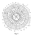
- Fig. 1 shows a section through a liquid ring compressor according to the invention 1.
- the liquid ring compressor 1 comprises a liquid ring compressor housing 2 with an interior 2a, wherein in the interior 2a a rotatable impeller 4 is arranged, wherein the impeller 4 has a plurality of circumferentially spaced apart blades 4a, and wherein the impeller 4 is rotatably mounted about a center of rotation 4b.
- a fixed inlet and outlet device 6 is arranged, which has two circumferentially extending inlet openings 7 and two circumferentially extending outlet openings 8.
- the inlet and outlet device 6 is also referred to as internal distributor.
- the liquid ring compressor 1 is configured in the illustrated embodiment as a double-flow pump by having these two inlet openings 7, two outlet openings 8 and also two mutual compression spaces 10a.
- the interior 2a is bounded in the circumferential direction by a housing inner wall 3, which surrounds the impeller 4 in the circumferential direction from the outside, wherein the housing inner wall 3 is aligned to the impeller 4 out.
- the housing inner wall 3 comprises a plurality of subsections 3a - 3n, which together form the in Form the circumferential direction of the housing inner wall 3.
- In the interior 2a is a liquid which is conveyed by the impeller 4 in the direction of rotation 5, and which forms a liquid ring 9 with a boundary line 9a.
- the space between the boundary line 9a and the inlet and outlet device 6 forms a delivery chamber 10, within which a gas is pumped from the inlet opening 7 to the outlet opening 8.
- the conveying space 10 is divided in the circumferential direction into a plurality of successively following partial conveying spaces 10a which are mutually bounded by a respective blade 4a, wherein the volume of the partial conveying spaces 10a in the region of the inlet opening 7 increases in the direction 9b and thereby carries out a suction movement, and wherein reduces the volume of the sub-conveying spaces 10a toward the outlet opening 8 in the direction 9c, whereby a compression movement is performed.
- This pumping process takes place both in the FIG. 1
- the housing inner wall 3 has a first section 3d and a third section 3f, which run concentric to the center of rotation 4b of the impeller 4 and the center of rotation 4b a distance R or a radius of excision R e , also referred to as Exzentrizticianskrümmungsradius R e .
- a second subsection 3e extends between the first subsection 3d and the third subsection 3f.
- a fourth subsection 3g extends between the third subsection 3f and the first subsection 3d.
- the housing inner wall 3 has at the transitions of the sections 3d, 3e, 3f, 3g each have a kink K1, K2, K3, K4 on. These can be edged, angular or rounded.
- the liquid ring compressor 1 has a first center 11a and a second center 11b, which are spaced by the same length with respect to the center of rotation 4b of the impeller 4.
- the dashed line 11c shows a circle with first center 11a and eccentricity radius R e .
- the dashed line 11d shows a circle with the second center 11b and the eccentricity radius R e .
- the housing inner wall 3 also has two opposite eccentricity points 3h, at which the housing inner wall 3 has the greatest distance with respect to the center of rotation 4b.
- the housing inner wall 3 runs along the second part section 3e such that the second part section 3e has no kinks, and that the second part section 3e has sections with different radii of curvature.
- This configuration of the course of the housing inner wall 3 has the consequence that the suction movement 9b of the boundary line 9a is increased or increased, and that the compression movement 9c of the boundary line 9a is increased or amplified, resulting in an increase in the pumping capacity of the liquid ring compressor 1 result.
- the radii Ri, Rk, Rl, Rm can vary in the circumferential direction. In a further advantageous embodiment, however, each of the radii Ri, Rk, Rl, Rm may also have a constant value.
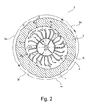
- FIG. 2 shows in a section perpendicular to the axis of rotation 4b, a further embodiment of a liquid ring compressor 1 with housing 2 and housing inner wall 3, wherein the liquid ring pump 1 is out of operation and therefore in the interior of the liquid ring compressor 1 no fluid.
- the liquid ring compressor 1 has, as ready in FIG. 1 described, a housing inner wall 3 with circumferentially successively arranged first, second, third and fourth section 3d, 3e, 3f, 3g and arranged therebetween kinks or transition areas K1, K2, K3, K4.
- all four radii Ri, Rk, Rl, Rm in the subsection 3e have a constant value.
- the two radii Rm and Ri are larger than the eccentricity radius R e , whereas the two radii Rk and Rl are smaller than the eccentricity radius R e .
- the portion 3e no kinks, which means that the sections with radii Rl, Rm, Ri, Rk at their transition points u 1, 3h and u4 in the direction of rotation 5 are mutually tangential, so that these transition points u 1, 3h and u4 have no kink or discontinuity.
- FIG. 3 shows a detail view of the left upper part of in FIG. 2
- the second section 3e comprises the following four sections successively in the direction of rotation 5, a seventh section 31 with radius of curvature R1, an eighth section 3m with radius of curvature Rm, which follows the junction u4, a fifth section 3i with radius of curvature Ri, which follows after the eccentricity point 3h, and a sixth Subsection 3k with radius of curvature Rk, which follows after the transition point u 1.
- the second section 3e is mirror-symmetrical with respect to an axis passing through the points 3h and 4b.
- the circular path K represents the circle described by the outer edge (4c) of the blades 4a of the blade wheel 4.
- the distance A between the circular path K and the housing inner wall 3 increases from the region of the opening point 7a of the inlet opening 7 in the direction of rotation 5, and points in Eccentricity point 3h the highest value A1.
- the distance A then reduces to the region of the closing point 8b of the outlet opening eighth FIG. 3 also shows the circular line 11c, which is defined by a circle with eccentricity radius R e and the first center 11a.
- the housing inner wall 3 now runs along the fifth and sixth subsection 3i, 3k in such a way that the radius of curvature Ri has a greater value than the eccentricity radius R e , so that the fifth subsection 3i moves further away from the circular line 11c, and that the radius of curvature Rk is smaller Has value as the eccentricity radius R e , so that the sixth portion 3k of the circular line 11c approaches again.
- the sixth section 3k is in an advantageous embodiment as in FIG. 3 represented along the outlet opening 8 arranged to effect through the course of the housing inner wall 3 along the sixth section 3k an increased compression movement 9c on the liquid ring 9 or on its boundary line 9a, thereby increasing the conveying effect to the outlet port 8 out.
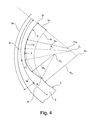
- FIG. 4 shows a further embodiment of a course of the housing inner wall 3.
- the left half of the second section 3e is shown, which is a fifth Part 3i and a sixth section 3k includes.
- the fifth section 3i has a radius of curvature Ri with a center of rotation zi.
- the sixth section 3k has a radius of curvature Rk with a center of rotation zk.
- the radii Ri, Rk and the centers of rotation zi, zk are dimensioned and arranged such that the tangents of the fifth and sixth part sections 3i, 3k are identical at the transition point u 1, so that the transition point u1 has no kink or discontinuity.
- the radii of curvature Ri, Rk could also have varying values in the direction of rotation 5, preferably such that the radii Ri are greater than R and that the radii Rk are smaller than R, and preferably such that the tangents of the fifth and sixth part sections 3i, 3k are identical at the transition point u 1.
- FIG. 5 shows a partial view of a section through the in FIG. 1 shown liquid ring compressor 1 along the section line BB. From this, the course of the blade wheel 4 with blade 4a within the housing 2 can be seen.
Abstract
Description
Die Erfindung betrifft einen Flüssigkeitsringverdichter gemäss dem Oberbegriff von Anspruch 1.The invention relates to a liquid ring compressor according to the preamble of
Die Druckschrift
Aufgabe der Erfindung ist es einen wirtschaftlich vorteilhafteren Flüssigkeitsringverdichter zu bilden, welche insbesondere einen verbesserten Wirkungsgrad aufweist.The object of the invention is to form an economically advantageous liquid ring compressor, which in particular has an improved efficiency.
Diese Aufgabe wird gelöst mit einem Flüssigkeitsringverdichter aufweisend die Merkmale von Anspruch 1. Die Unteransprüche 2 bis 10 betreffen weitere, vorteilhafte Ausgestaltungen.This object is achieved with a liquid ring compressor having the features of
Die Aufgabe wird insbesondere gelöst mit einem Flüssigkeitsringverdichter umfassend ein Ringgehäuse sowie ein Schaufelrad, wobei das Schaufelrad innerhalb des Ringgehäuses angeordnet ist und um eine Drehachse und in eine Drehrichtung drehbar gelagert ist, wobei das Schaufelrad eine Mehrzahl von in Drehrichtung gegenseitig beabstandet angeordnete Schaufeln aufweist, und wobei das Ringgehäuse eine zum Schaufelrad hin ausgerichtete, in Umfangsrichtung verlaufende Gehäuseinnenwand aufweist, wobei die Gehäuseinnenwand einen ersten Teilabschnitt und einen dritten Teilabschnitt aufweist, die bezüglich der Drehachse gekrümmt, vorzugsweise kreisförmig und mit einem Exzentrizitätskrümmungsradius verlaufen, und die bezüglich der Drehachse gegenüberliegend und gegenseitig symmetrisch verlaufend angeordnet sind, und wobei die Gehäuseinnenwand einen zweiten Teilabschnitt aufweist, der den ersten Teilabschnitt mit dem dritten Teilabschnitt verbindet, und wobei der zweite Teilabschnitt zwischen dem ersten Teilabschnitt und dem dritten Teilabschnitt einen Exzentrizitätspunkt aufweist, welcher in zur Drehachse radialen Richtung bezüglich einer durch die Aussenkanten der Schaufeln definierten Kreisbahn einen maximalen Abstand aufweist, und wobei der zweite Teilabschnitt zwischen dem Exzentrizitätspunkt und dem dritten Teilabschnitt in Drehrichtung aus einem fünften und einem sechsten Teilabschnitt besteht, wobei der fünfte Teilabschnitt einen gekrümmten Verlauf aufweist mit Krümmungsradien die grösser sind als der Exzentrizitätskrümmungsradius des ersten Teilabschnittes, und wobei der sechste Teilabschnitt einen gekrümmten Verlauf aufweist mit Krümmungsradien die kleiner sind als der Exzentrizitätskrümmungsradius des ersten Teilabschnittes, und wobei der fünfte und sechste Teilabschnitt an deren Übergangsstelle gegenseitig tangential verlaufen, und wobei innerhalb des Ringgehäuses eine Ein- und Auslassvorrichtung angeordnet ist, welche eine Auslassöffnung aufweist, wobei sich die Auslassöffnung innerhalb des Bereichs zwischen dem Exzentrizitätspunkt und dem dritten Teilabschnitt in Drehrichtung streckt. Die sich in Drehrichtung erstreckende Auslassöffnung erstreckt sich vorzugsweise entlang eines Teilabschnittes des Bereichs zwischen dem Exzentrizitätspunkt und dem dritten Teilabschnitt.The object is achieved in particular with a liquid ring compressor comprising a ring housing and a paddle wheel, wherein the paddle wheel is arranged within the ring housing and is rotatably mounted about a rotation axis and in a rotational direction, wherein the paddle wheel has a plurality of spaced apart in the direction of rotation blades, and wherein the ring housing has a circumferentially extending housing inner wall oriented toward the paddle wheel, the housing inner wall having a first section and a third section which are curved with respect to the axis of rotation, preferably circular and with an eccentricity radius of curvature, and which are mutually symmetrical with respect to the axis of rotation are arranged extending, and wherein the housing inner wall has a second portion which connects the first portion to the third portion, and wherein the second portion between the first subsection and the third subsection has an eccentricity point which has a maximum distance in a direction radial to the axis of rotation with respect to a circular path defined by the outer edges of the blades, and wherein the second subsection between the eccentricity point and the third subsection in the direction of rotation consists of a fifth and a sixth subsection, the fifth subsection having a curved course having radii of curvature greater than the eccentricity curvature radius of the first subsection, and wherein the sixth subsection has a curved course with radii of curvature smaller than the radius of curvature of the eccentricity of the first section, and with the fifth and sixth sections mutually tangent at their transition point, and inside the ring housing an inlet and outlet device having an outlet opening, the outlet opening being within the outlet opening Range between the Exzentrizitätspunkt and the third section in the direction of rotation stretches. The rotationally extending outlet opening preferably extends along a partial section of the region between the point of eccentricity and the third partial section.
Der Verlauf der Gehäuseinnenwand des erfindungsgemässen Flüssigkeitsringverdichters weist den Vorteil auf, dass das Ausstossen im Bereich der Auslassöffnung vorteilhafter erfolgt. In einer vorteilhaften Ausgestaltung wird das Volumen des Flüssigkeitsringverdichters im Bereich der Auslassöffnung in Drehrichtung zunehmend verkleinert, was zur Folge hat, das das vom Flüssigkeitsringverdichter zu pumpende Fluid im Bereich der Auslassöffnung eine Druckerhöhung erfährt, sodass das zu pumpende Fluid mit einem höheren Druck zur Auslassöffnung hin gefördert wird.The profile of the housing inner wall of the inventive liquid ring compressor has the advantage that the ejection in the region of the outlet opening takes place more advantageously. In an advantageous embodiment, the volume of the liquid ring compressor in the region of the outlet opening in the direction of rotation is increasingly reduced, with the result that the liquid to be pumped by the liquid ring compressor experiences an increase in pressure in the region of the outlet opening, so that the fluid to be pumped at a higher pressure toward the outlet opening is encouraged.
In einer weiteren vorteilhaften Ausführungsform ist die Gehäuseinnenwand des erfindungsgemässen Flüssigkeitsringverdichters derart ausgestaltet, dass sich der Ansaugraum des Flüssigkeitsringverdichters im Bereich der Einlassöffnung in Drehrichtung zusätzlich vergrössert, was zur Folge hat, dass der Flüssigkeitsringverdichter ein grösseres Ansaugvolumen aufweist, sodass eine grössere Menge des zu pumpenden Fluids über die Einlassöffnung in das Ansaugvolumen gelangt.In a further advantageous embodiment, the housing inner wall of the inventive liquid ring compressor is designed such that the suction of the liquid ring compressor in the inlet opening in the direction of rotation additionally increases, with the result that the liquid ring compressor has a larger intake volume, so that a larger amount of fluid to be pumped enters the intake volume via the inlet opening.
Der erfindungsgemässe Flüssigkeitsringverdichter könnte auch als Flüssigkeitsringpumpe, Flüssigkeitsringvakuumpumpe oder Flüssigkeitsringkompressor oder Flüssigkeitsringvakuumkompressor bezeichnet bzw. eingesetzt werden.The inventive liquid ring compressor could also be called or used as a liquid ring pump, liquid ring vacuum pump or liquid ring compressor or liquid ring vacuum compressor.
Die Erfindung wird nachfolgend an Hand von Ausführungsbeispielen im Detail erläutert.The invention will be explained below with reference to exemplary embodiments in detail.
Die zur Erläuterung der Ausführungsbeispiele verwendeten Zeichnungen zeigen:
- Fig. 1
- einen senkrecht zur Achse des Schaufelrades verlaufenden Schnitt durch einen Flüssigkeitsringverdichter umfassend ein Gehäuse sowie einen Rotor;
- Fig. 2
- einen Schnitt durch ein weiteres Ausführungsbeispiel eines Flüssigkeitsringverdichters;
- Fig. 3
- eine Detailansicht des linken Teils der in
Figur 2 - Fig. 4
- eine Detailansicht eines weiteren Ausführungsbeispiel eines Flüssigkeitsringverdichters;
- Fig. 5
- einen Schnitt durch
Figur 1
- Fig. 1
- a section perpendicular to the axis of the impeller through a liquid ring compressor comprising a housing and a rotor;
- Fig. 2
- a section through another embodiment of a liquid ring compressor;
- Fig. 3
- a detail view of the left part of the in
FIG. 2 illustrated liquid ring compressor; - Fig. 4
- a detailed view of another embodiment of a liquid ring compressor;
- Fig. 5
- a cut through
FIG. 1 along the section line BB.
Grundsätzlich sind in den Zeichnungen gleiche Teile mit gleichen Bezugszeichen versehen.Basically, the same parts are given the same reference numerals in the drawings.
Im dargestellten Ausführungsbeispiel weist die Gehäuseinnenwand 3 einen ersten Teilabschnitt 3d und einen dritten Teilabschnitt 3f auf, welche konzentrisch zum Drehzentrum 4b des Schaufelrades 4 verlaufen und zum Drehzentrum 4b einen Abstand R beziehungsweise einen Exzentrizitätsradius Re, auch als Exzentrizitätskrümmungsradius Re bezeichnet, aufweisen. Ein zweiter Teilabschnitt 3e verläuft zwischen dem ersten Teilabschnitt 3d und dem dritten Teilabschnitt 3f. Ein vierter Teilabschnitt 3g verläuft zwischen dem dritten Teilabschnitt 3f und dem ersten Teilabschnitt 3d. Die Gehäuseinnenwand 3 weist an den Übergängen der Teilabschnitte 3d,3e,3f,3g jeweils eine Knickstelle K1, K2, K3, K4 auf. Diese können kantig, eckig oder auch abgerundet ausgestaltet sein. Der Flüssigkeitsringverdichter 1 weist ein ersten Zentrum 11a sowie ein zweites Zentrum 11b auf, welche bezüglich dem Drehzentrum 4b des Schaufelrades 4 um dieselbe Länge beabstandet sind. Die strichlierte Linie 11c zeigt einen Kreis mit erstem Zentrum 11a und Exzentrizitätsradius Re. Die strichlierte Linie 11d zeigt einen Kreis mit zweitem Zentrum 11b und Exzentrizitätsradius Re. Die Gehäuseinnenwand 3 weist zudem zwei gegenüberliegende Exzentrizitätspunkte 3h auf, an welchen die Gehäuseinnenwand 3 bezüglich dem Drehzentrum 4b den grössten Abstand aufweist. In einer vorteilhaften Ausgestaltung verläuft die Gehäuseinnenwand 3 entlang des zweiten Teilabschnittes 3e derart, dass der zweite Teilabschnitt 3e keine Knickstellen aufweist, und dass der zweite Teilabschnitt 3e Abschnitte mit unterschiedlichen Krümmungsradien aufweist. In der am meisten bevorzugten Ausgestaltung weist die Gehäuseinnenwand 3 entlang des zweiten Teilabschnittes 3e im Bereich des Öffnungspunktes 7a der Einlassöffnung 7 und /oder im Bereich des Schliesspunktes 8b der Auslassöffnung 8 Krümmungsradien Rl, Rk auf, die kleiner ist als der Exzentrizitätsradius Re, wogegen der zweite Teilabschnitt 3e dazwischen Krümmungsradien Rm, Ri aufweist, die grösser sind als der Exzentrizitätsradius Re. Diese Ausgestaltung des Verlaufs der Gehäuseinnenwand 3 hat zur Folge, dass die Saugbewegung 9b der Grenzlinie 9a vergrössert beziehungsweise verstärkt wird, und dass die Kompressionsbewegung 9c der Grenzlinie 9a vergrössert beziehungsweise verstärkt wird, was eine Vergrösserung der Pumpleistung des Flüssigkeitsringverdichters 1 zur Folge hat. Die Radien Ri, Rk, Rl, Rm können sich in Umfangsrichtung verändern. In einer weiteren vorteilhaften Ausgestaltung kann jeder der Radien Ri, Rk, Rl, Rm jedoch auch einen konstanten Wert aufweisen.In the illustrated embodiment, the housing
Claims (10)
Priority Applications (2)
| Application Number | Priority Date | Filing Date | Title |
|---|---|---|---|
| EP20110186724 EP2587065B1 (en) | 2011-10-26 | 2011-10-26 | Liquid ring compressor |
| PCT/EP2012/071101 WO2013060754A2 (en) | 2011-10-26 | 2012-10-25 | Liquid ring compressor |
Applications Claiming Priority (1)
| Application Number | Priority Date | Filing Date | Title |
|---|---|---|---|
| EP20110186724 EP2587065B1 (en) | 2011-10-26 | 2011-10-26 | Liquid ring compressor |
Publications (2)
| Publication Number | Publication Date |
|---|---|
| EP2587065A1 true EP2587065A1 (en) | 2013-05-01 |
| EP2587065B1 EP2587065B1 (en) | 2014-06-04 |
Family
ID=47222016
Family Applications (1)
| Application Number | Title | Priority Date | Filing Date |
|---|---|---|---|
| EP20110186724 Active EP2587065B1 (en) | 2011-10-26 | 2011-10-26 | Liquid ring compressor |
Country Status (2)
| Country | Link |
|---|---|
| EP (1) | EP2587065B1 (en) |
| WO (1) | WO2013060754A2 (en) |
Cited By (1)
| Publication number | Priority date | Publication date | Assignee | Title |
|---|---|---|---|---|
| WO2017013382A1 (en) * | 2015-07-22 | 2017-01-26 | Edwards Limited | Abatement system |
Citations (3)
| Publication number | Priority date | Publication date | Assignee | Title |
|---|---|---|---|---|
| DE1021976B (en) * | 1951-02-15 | 1958-01-02 | Nash Engineering Co | Liquid ring gas pump |
| DE1428084A1 (en) * | 1964-01-02 | 1968-11-21 | Dardelet Robert Leon | Liquid ring gas pump |
| EP0565232B1 (en) | 1992-04-09 | 1996-07-03 | The Nash Engineering Company | Liquid ring pumps with improved housing shapes |
-
2011
- 2011-10-26 EP EP20110186724 patent/EP2587065B1/en active Active
-
2012
- 2012-10-25 WO PCT/EP2012/071101 patent/WO2013060754A2/en active Application Filing
Patent Citations (3)
| Publication number | Priority date | Publication date | Assignee | Title |
|---|---|---|---|---|
| DE1021976B (en) * | 1951-02-15 | 1958-01-02 | Nash Engineering Co | Liquid ring gas pump |
| DE1428084A1 (en) * | 1964-01-02 | 1968-11-21 | Dardelet Robert Leon | Liquid ring gas pump |
| EP0565232B1 (en) | 1992-04-09 | 1996-07-03 | The Nash Engineering Company | Liquid ring pumps with improved housing shapes |
Cited By (3)
| Publication number | Priority date | Publication date | Assignee | Title |
|---|---|---|---|---|
| WO2017013382A1 (en) * | 2015-07-22 | 2017-01-26 | Edwards Limited | Abatement system |
| KR20180031684A (en) * | 2015-07-22 | 2018-03-28 | 에드워즈 리미티드 | Abatement system |
| US10099169B2 (en) | 2015-07-22 | 2018-10-16 | Edwards Limited | Abatement system |
Also Published As
| Publication number | Publication date |
|---|---|
| WO2013060754A2 (en) | 2013-05-02 |
| EP2587065B1 (en) | 2014-06-04 |
| WO2013060754A3 (en) | 2013-09-26 |
Similar Documents
| Publication | Publication Date | Title |
|---|---|---|
| DE10327574B4 (en) | Impeller for a fuel pump | |
| EP1828611B1 (en) | Vane pump | |
| WO2012041625A1 (en) | Side channel blower, in particular a secondary air blower for an internal combustion machine | |
| EP3140548B1 (en) | Impeller for regenerative pump | |
| EP1828609B1 (en) | Vane cell pump | |
| EP3034780A1 (en) | Rotary pump with compact positioning structure for adjusting displacement | |
| DE102007032228A1 (en) | Self-priming pump aggregation | |
| WO2016110373A1 (en) | Side-channel blower for an internal combustion engine | |
| DE876285C (en) | Ring compressor | |
| WO2010142287A1 (en) | Compressor impeller | |
| DE3128372A1 (en) | "PERIPHERAL CHANNEL PUMP" | |
| EP2587065B1 (en) | Liquid ring compressor | |
| DE102010005517B4 (en) | dispersing pump | |
| DE102015007100A1 (en) | Self-priming pump aggregation | |
| DE102011106525A1 (en) | Dispersion pump e.g. single-stage, normal or suction centrifugal pump, for conveying/mixing substances in food and beverage process, has intermediate shovel for dividing channel into exit channels and arranged in exit-side region of channel | |
| EP3224480B1 (en) | Compressor having a sealing channel | |
| DE2249591A1 (en) | VANE PUMP | |
| EP1948935B1 (en) | Pump | |
| EP2342465B1 (en) | Side channel blower, in particular secondary air blower for an internal combustion engine | |
| DE1653815A1 (en) | Eccentric scroll pump | |
| EP3728860B1 (en) | Side channel blower, in particular secondary air blower for an internal combustion engine | |
| WO2016202711A1 (en) | Turbocharger for a motor vehicle | |
| DE2230773A1 (en) | DISPLACEMENT MACHINE | |
| DE102006036439A1 (en) | Conveying unit e.g. roller vane pump, has pressure channel loading rear groove chamber with pressure at outlet during zero to five degree rotation of rotor from point of time at which working chamber is not connected with inlet | |
| DE102021125708A1 (en) | flow guide structure |
Legal Events
| Date | Code | Title | Description |
|---|---|---|---|
| PUAI | Public reference made under article 153(3) epc to a published international application that has entered the european phase |
Free format text: ORIGINAL CODE: 0009012 |
|
| AK | Designated contracting states |
Kind code of ref document: A1 Designated state(s): AL AT BE BG CH CY CZ DE DK EE ES FI FR GB GR HR HU IE IS IT LI LT LU LV MC MK MT NL NO PL PT RO RS SE SI SK SM TR |
|
| AX | Request for extension of the european patent |
Extension state: BA ME |
|
| GRAP | Despatch of communication of intention to grant a patent |
Free format text: ORIGINAL CODE: EPIDOSNIGR1 |
|
| 17P | Request for examination filed |
Effective date: 20131029 |
|
| RBV | Designated contracting states (corrected) |
Designated state(s): AL AT BE BG CH CY CZ DE DK EE ES FI FR GB GR HR HU IE IS IT LI LT LU LV MC MK MT NL NO PL PT RO RS SE SI SK SM TR |
|
| INTG | Intention to grant announced |
Effective date: 20131205 |
|
| GRAS | Grant fee paid |
Free format text: ORIGINAL CODE: EPIDOSNIGR3 |
|
| GRAP | Despatch of communication of intention to grant a patent |
Free format text: ORIGINAL CODE: EPIDOSNIGR1 |
|
| GRAA | (expected) grant |
Free format text: ORIGINAL CODE: 0009210 |
|
| INTG | Intention to grant announced |
Effective date: 20140417 |
|
| AK | Designated contracting states |
Kind code of ref document: B1 Designated state(s): AL AT BE BG CH CY CZ DE DK EE ES FI FR GB GR HR HU IE IS IT LI LT LU LV MC MK MT NL NO PL PT RO RS SE SI SK SM TR |
|
| REG | Reference to a national code |
Ref country code: GB Ref legal event code: FG4D Free format text: NOT ENGLISH |
|
| REG | Reference to a national code |
Ref country code: CH Ref legal event code: EP |
|
| REG | Reference to a national code |
Ref country code: AT Ref legal event code: REF Ref document number: 671242 Country of ref document: AT Kind code of ref document: T Effective date: 20140615 |
|
| RAP2 | Party data changed (patent owner data changed or rights of a patent transferred) |
Owner name: POMPETRAVAINI NSB AG |
|
| REG | Reference to a national code |
Ref country code: IE Ref legal event code: FG4D Free format text: LANGUAGE OF EP DOCUMENT: GERMAN |
|
| REG | Reference to a national code |
Ref country code: DE Ref legal event code: R096 Ref document number: 502011003269 Country of ref document: DE Effective date: 20140717 |
|
| REG | Reference to a national code |
Ref country code: NL Ref legal event code: VDEP Effective date: 20140604 |
|
| PG25 | Lapsed in a contracting state [announced via postgrant information from national office to epo] |
Ref country code: FI Free format text: LAPSE BECAUSE OF FAILURE TO SUBMIT A TRANSLATION OF THE DESCRIPTION OR TO PAY THE FEE WITHIN THE PRESCRIBED TIME-LIMIT Effective date: 20140604 Ref country code: NO Free format text: LAPSE BECAUSE OF FAILURE TO SUBMIT A TRANSLATION OF THE DESCRIPTION OR TO PAY THE FEE WITHIN THE PRESCRIBED TIME-LIMIT Effective date: 20140904 Ref country code: LT Free format text: LAPSE BECAUSE OF FAILURE TO SUBMIT A TRANSLATION OF THE DESCRIPTION OR TO PAY THE FEE WITHIN THE PRESCRIBED TIME-LIMIT Effective date: 20140604 Ref country code: GR Free format text: LAPSE BECAUSE OF FAILURE TO SUBMIT A TRANSLATION OF THE DESCRIPTION OR TO PAY THE FEE WITHIN THE PRESCRIBED TIME-LIMIT Effective date: 20140905 Ref country code: CY Free format text: LAPSE BECAUSE OF FAILURE TO SUBMIT A TRANSLATION OF THE DESCRIPTION OR TO PAY THE FEE WITHIN THE PRESCRIBED TIME-LIMIT Effective date: 20140604 |
|
| REG | Reference to a national code |
Ref country code: LT Ref legal event code: MG4D |
|
| PG25 | Lapsed in a contracting state [announced via postgrant information from national office to epo] |
Ref country code: HR Free format text: LAPSE BECAUSE OF FAILURE TO SUBMIT A TRANSLATION OF THE DESCRIPTION OR TO PAY THE FEE WITHIN THE PRESCRIBED TIME-LIMIT Effective date: 20140604 Ref country code: SE Free format text: LAPSE BECAUSE OF FAILURE TO SUBMIT A TRANSLATION OF THE DESCRIPTION OR TO PAY THE FEE WITHIN THE PRESCRIBED TIME-LIMIT Effective date: 20140604 Ref country code: RS Free format text: LAPSE BECAUSE OF FAILURE TO SUBMIT A TRANSLATION OF THE DESCRIPTION OR TO PAY THE FEE WITHIN THE PRESCRIBED TIME-LIMIT Effective date: 20140604 Ref country code: LV Free format text: LAPSE BECAUSE OF FAILURE TO SUBMIT A TRANSLATION OF THE DESCRIPTION OR TO PAY THE FEE WITHIN THE PRESCRIBED TIME-LIMIT Effective date: 20140604 |
|
| PG25 | Lapsed in a contracting state [announced via postgrant information from national office to epo] |
Ref country code: RO Free format text: LAPSE BECAUSE OF FAILURE TO SUBMIT A TRANSLATION OF THE DESCRIPTION OR TO PAY THE FEE WITHIN THE PRESCRIBED TIME-LIMIT Effective date: 20140604 Ref country code: CZ Free format text: LAPSE BECAUSE OF FAILURE TO SUBMIT A TRANSLATION OF THE DESCRIPTION OR TO PAY THE FEE WITHIN THE PRESCRIBED TIME-LIMIT Effective date: 20140604 Ref country code: ES Free format text: LAPSE BECAUSE OF FAILURE TO SUBMIT A TRANSLATION OF THE DESCRIPTION OR TO PAY THE FEE WITHIN THE PRESCRIBED TIME-LIMIT Effective date: 20140604 Ref country code: EE Free format text: LAPSE BECAUSE OF FAILURE TO SUBMIT A TRANSLATION OF THE DESCRIPTION OR TO PAY THE FEE WITHIN THE PRESCRIBED TIME-LIMIT Effective date: 20140604 Ref country code: SK Free format text: LAPSE BECAUSE OF FAILURE TO SUBMIT A TRANSLATION OF THE DESCRIPTION OR TO PAY THE FEE WITHIN THE PRESCRIBED TIME-LIMIT Effective date: 20140604 Ref country code: PT Free format text: LAPSE BECAUSE OF FAILURE TO SUBMIT A TRANSLATION OF THE DESCRIPTION OR TO PAY THE FEE WITHIN THE PRESCRIBED TIME-LIMIT Effective date: 20141006 |
|
| PG25 | Lapsed in a contracting state [announced via postgrant information from national office to epo] |
Ref country code: PL Free format text: LAPSE BECAUSE OF FAILURE TO SUBMIT A TRANSLATION OF THE DESCRIPTION OR TO PAY THE FEE WITHIN THE PRESCRIBED TIME-LIMIT Effective date: 20140604 Ref country code: IS Free format text: LAPSE BECAUSE OF FAILURE TO SUBMIT A TRANSLATION OF THE DESCRIPTION OR TO PAY THE FEE WITHIN THE PRESCRIBED TIME-LIMIT Effective date: 20141004 Ref country code: NL Free format text: LAPSE BECAUSE OF FAILURE TO SUBMIT A TRANSLATION OF THE DESCRIPTION OR TO PAY THE FEE WITHIN THE PRESCRIBED TIME-LIMIT Effective date: 20140604 |
|
| REG | Reference to a national code |
Ref country code: DE Ref legal event code: R097 Ref document number: 502011003269 Country of ref document: DE |
|
| PLBE | No opposition filed within time limit |
Free format text: ORIGINAL CODE: 0009261 |
|
| STAA | Information on the status of an ep patent application or granted ep patent |
Free format text: STATUS: NO OPPOSITION FILED WITHIN TIME LIMIT |
|
| PG25 | Lapsed in a contracting state [announced via postgrant information from national office to epo] |
Ref country code: DK Free format text: LAPSE BECAUSE OF FAILURE TO SUBMIT A TRANSLATION OF THE DESCRIPTION OR TO PAY THE FEE WITHIN THE PRESCRIBED TIME-LIMIT Effective date: 20140604 |
|
| REG | Reference to a national code |
Ref country code: DE Ref legal event code: R119 Ref document number: 502011003269 Country of ref document: DE |
|
| 26N | No opposition filed |
Effective date: 20150305 |
|
| PG25 | Lapsed in a contracting state [announced via postgrant information from national office to epo] |
Ref country code: MC Free format text: LAPSE BECAUSE OF FAILURE TO SUBMIT A TRANSLATION OF THE DESCRIPTION OR TO PAY THE FEE WITHIN THE PRESCRIBED TIME-LIMIT Effective date: 20140604 Ref country code: LU Free format text: LAPSE BECAUSE OF FAILURE TO SUBMIT A TRANSLATION OF THE DESCRIPTION OR TO PAY THE FEE WITHIN THE PRESCRIBED TIME-LIMIT Effective date: 20141026 |
|
| REG | Reference to a national code |
Ref country code: CH Ref legal event code: PL |
|
| REG | Reference to a national code |
Ref country code: DE Ref legal event code: R097 Ref document number: 502011003269 Country of ref document: DE Effective date: 20150305 |
|
| PG25 | Lapsed in a contracting state [announced via postgrant information from national office to epo] |
Ref country code: BE Free format text: LAPSE BECAUSE OF NON-PAYMENT OF DUE FEES Effective date: 20141031 |
|
| REG | Reference to a national code |
Ref country code: IE Ref legal event code: MM4A |
|
| PG25 | Lapsed in a contracting state [announced via postgrant information from national office to epo] |
Ref country code: DE Free format text: LAPSE BECAUSE OF NON-PAYMENT OF DUE FEES Effective date: 20150501 Ref country code: SI Free format text: LAPSE BECAUSE OF FAILURE TO SUBMIT A TRANSLATION OF THE DESCRIPTION OR TO PAY THE FEE WITHIN THE PRESCRIBED TIME-LIMIT Effective date: 20140604 Ref country code: LI Free format text: LAPSE BECAUSE OF NON-PAYMENT OF DUE FEES Effective date: 20141031 Ref country code: CH Free format text: LAPSE BECAUSE OF NON-PAYMENT OF DUE FEES Effective date: 20141031 |
|
| REG | Reference to a national code |
Ref country code: FR Ref legal event code: ST Effective date: 20150630 |
|
| PG25 | Lapsed in a contracting state [announced via postgrant information from national office to epo] |
Ref country code: FR Free format text: LAPSE BECAUSE OF NON-PAYMENT OF DUE FEES Effective date: 20141031 |
|
| PG25 | Lapsed in a contracting state [announced via postgrant information from national office to epo] |
Ref country code: IE Free format text: LAPSE BECAUSE OF NON-PAYMENT OF DUE FEES Effective date: 20141026 |
|
| PG25 | Lapsed in a contracting state [announced via postgrant information from national office to epo] |
Ref country code: SM Free format text: LAPSE BECAUSE OF FAILURE TO SUBMIT A TRANSLATION OF THE DESCRIPTION OR TO PAY THE FEE WITHIN THE PRESCRIBED TIME-LIMIT Effective date: 20140604 |
|
| GBPC | Gb: european patent ceased through non-payment of renewal fee |
Effective date: 20151026 |
|
| PG25 | Lapsed in a contracting state [announced via postgrant information from national office to epo] |
Ref country code: BG Free format text: LAPSE BECAUSE OF FAILURE TO SUBMIT A TRANSLATION OF THE DESCRIPTION OR TO PAY THE FEE WITHIN THE PRESCRIBED TIME-LIMIT Effective date: 20140604 |
|
| PG25 | Lapsed in a contracting state [announced via postgrant information from national office to epo] |
Ref country code: TR Free format text: LAPSE BECAUSE OF FAILURE TO SUBMIT A TRANSLATION OF THE DESCRIPTION OR TO PAY THE FEE WITHIN THE PRESCRIBED TIME-LIMIT Effective date: 20140604 Ref country code: HU Free format text: LAPSE BECAUSE OF FAILURE TO SUBMIT A TRANSLATION OF THE DESCRIPTION OR TO PAY THE FEE WITHIN THE PRESCRIBED TIME-LIMIT; INVALID AB INITIO Effective date: 20111026 Ref country code: GB Free format text: LAPSE BECAUSE OF NON-PAYMENT OF DUE FEES Effective date: 20151026 Ref country code: MT Free format text: LAPSE BECAUSE OF FAILURE TO SUBMIT A TRANSLATION OF THE DESCRIPTION OR TO PAY THE FEE WITHIN THE PRESCRIBED TIME-LIMIT Effective date: 20140604 |
|
| REG | Reference to a national code |
Ref country code: AT Ref legal event code: MM01 Ref document number: 671242 Country of ref document: AT Kind code of ref document: T Effective date: 20161026 |
|
| PG25 | Lapsed in a contracting state [announced via postgrant information from national office to epo] |
Ref country code: AT Free format text: LAPSE BECAUSE OF NON-PAYMENT OF DUE FEES Effective date: 20161026 |
|
| PG25 | Lapsed in a contracting state [announced via postgrant information from national office to epo] |
Ref country code: MK Free format text: LAPSE BECAUSE OF FAILURE TO SUBMIT A TRANSLATION OF THE DESCRIPTION OR TO PAY THE FEE WITHIN THE PRESCRIBED TIME-LIMIT Effective date: 20140604 |
|
| PG25 | Lapsed in a contracting state [announced via postgrant information from national office to epo] |
Ref country code: AL Free format text: LAPSE BECAUSE OF FAILURE TO SUBMIT A TRANSLATION OF THE DESCRIPTION OR TO PAY THE FEE WITHIN THE PRESCRIBED TIME-LIMIT Effective date: 20140604 |
|
| PGFP | Annual fee paid to national office [announced via postgrant information from national office to epo] |
Ref country code: IT Payment date: 20231019 Year of fee payment: 13 |