EP0565232B1 - Liquid ring pumps with improved housing shapes - Google Patents
Liquid ring pumps with improved housing shapes Download PDFInfo
- Publication number
- EP0565232B1 EP0565232B1 EP93301649A EP93301649A EP0565232B1 EP 0565232 B1 EP0565232 B1 EP 0565232B1 EP 93301649 A EP93301649 A EP 93301649A EP 93301649 A EP93301649 A EP 93301649A EP 0565232 B1 EP0565232 B1 EP 0565232B1
- Authority
- EP
- European Patent Office
- Prior art keywords
- pump
- rotor
- arc
- housing
- rotor axis
- Prior art date
- Legal status (The legal status is an assumption and is not a legal conclusion. Google has not performed a legal analysis and makes no representation as to the accuracy of the status listed.)
- Expired - Lifetime
Links
Images


Classifications
-
- F—MECHANICAL ENGINEERING; LIGHTING; HEATING; WEAPONS; BLASTING
- F04—POSITIVE - DISPLACEMENT MACHINES FOR LIQUIDS; PUMPS FOR LIQUIDS OR ELASTIC FLUIDS
- F04C—ROTARY-PISTON, OR OSCILLATING-PISTON, POSITIVE-DISPLACEMENT MACHINES FOR LIQUIDS; ROTARY-PISTON, OR OSCILLATING-PISTON, POSITIVE-DISPLACEMENT PUMPS
- F04C2/00—Rotary-piston machines or pumps
-
- F—MECHANICAL ENGINEERING; LIGHTING; HEATING; WEAPONS; BLASTING
- F01—MACHINES OR ENGINES IN GENERAL; ENGINE PLANTS IN GENERAL; STEAM ENGINES
- F01C—ROTARY-PISTON OR OSCILLATING-PISTON MACHINES OR ENGINES
- F01C21/00—Component parts, details or accessories not provided for in groups F01C1/00 - F01C20/00
- F01C21/10—Outer members for co-operation with rotary pistons; Casings
- F01C21/104—Stators; Members defining the outer boundaries of the working chamber
- F01C21/106—Stators; Members defining the outer boundaries of the working chamber with a radial surface, e.g. cam rings
-
- F—MECHANICAL ENGINEERING; LIGHTING; HEATING; WEAPONS; BLASTING
- F04—POSITIVE - DISPLACEMENT MACHINES FOR LIQUIDS; PUMPS FOR LIQUIDS OR ELASTIC FLUIDS
- F04C—ROTARY-PISTON, OR OSCILLATING-PISTON, POSITIVE-DISPLACEMENT MACHINES FOR LIQUIDS; ROTARY-PISTON, OR OSCILLATING-PISTON, POSITIVE-DISPLACEMENT PUMPS
- F04C19/00—Rotary-piston pumps with fluid ring or the like, specially adapted for elastic fluids
Definitions
- This invention relates to liquid ring pumps, and more particularly to liquid ring pumps in which the inner surfaces of the housings are shaped to reduce fluid friction losses in the pumps.
- Liquid ring pumps are well known as shown, for example, by Sommer U.S. patent 1,525,332 and Haavik U.S. patent 4,613,283. Russian inventor's certificate 529,295 points out that fluid friction in such pumps can be reduced by making the housing and turbine wheel of trapezoidal shape in axial section. According to this reference, by shaping the pump in this way the area of the housing surface contacted by the liquid is reduced, thereby reducing hydrodynamic loss in the pump.
- the pump design shown in the above-mentioned Russian inventor's certificate results in several parts having very complex shapes.
- the central housing element varies in axial length around the pump.
- the faces of the end housing elements which abut the central element do not lie in planes perpendicular to the rotor axis.
- the pump of the Russian inventor's certificate would therefore be relatively difficult and expensive to make.
- the trapezoidal shape shown in the Russian inventor's certificate may reduce hydrodynamic loss in the pump to some degree, there is a need for further reduction in such loss.
- WO-A-91/19904 describes a liquid ring pump in which the inner annular surface of the housing is curved to accommodate the liquid ring.
- the curved inner annular surface includes several discontinuities which contribute to the overall friction losses of the pump.
- DE-B-1014282 describes a liquid ring pump which includes an eccentric trench for accommodating the liquid ring.
- the trench is of a generally trapezoidal cross section, with slightly rounded edges, and this irregular shape will also lead to relatively high hydrodynamic losses in the pump.
- a liquid ring pump having a rotor rotatably mounted about a rotor axis in an annular housing for forming a quantity of liquid in the housing into a recirculating annular ring inside the annular inner surface of the housing such that the liquid ring moves radially outward from the rotor axis adjacent a gas intake zone of the pump and moves radially inward again adjacent a gas compression zone of the pump, said rotor having a plurality of circumferentially spaced, axially extending blades, the opposite axial ends of the radially outer edges of said blades lying in axially spaced first and second planes which are substantially perpendicular to said rotor axis, said annular inner surface of said housing being formed so that the intersection between said annular inner surface and substantially any plane in which said rotor axis lies is an arc that is concave as viewed from said rotor axis outward, and said annular inner surface being substantially free
- a liquid ring pump having a rotor rotatably mounted in an annular housing for forming a quantity of liquid in the housing into a recirculating annular ring inside the annular inner surface of the housing such that the liquid ring moves radially outward from the rotor axis adjacent a gas intake zone of the pump and moves radially inward again adjacent a gas compression zone of the pump, said rotor having a plurality of circumferentially spaced, axially extending blades, the opposite axial ends of the radial outer edges of said blades lying in axially spaced first and second planes which are substantially perpendicular to said rotor axis, characterised in that the annular inner surface of said housing is formed so that the intersection between said annular inner surface and substantially any plane which includes said rotor axis is a pair of axially adjacent, axially extending arcs joined at an intermediate cusp-like region, each said arc being concave as
- the arcs are circular because, of all geometric shapes, circles have the smallest ratio of circumference to area.
- the inner surface of the housing in contact with the portion of the liquid ring which is radially outside the rotor does not extend axially beyond the planes perpendicular to the rotor axis which include the axial ends of the radially outer edges of the rotor blades.
- each arc subtends an angle of no more than approximately 180°, and each arc extends to each of the above-mentioned planes perpendicular to the rotor axis.
- the center shroud defines a third plane perpendicular to the rotor axis, and each arc may either extend without axial discontinuity through that plane, or the inner surface of the housing may have a cusp in the third plane.
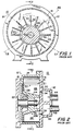
- FIG. 1 is a simplified cross sectional view of an illustrative conventional liquid ring pump.
- FIG. 1 is taken along the line 1-1 in FIG. 2.
- FIG. 2 is a sectional view taken along the line 2-2 in FIG. 1.
- FIG. 3 is a view similar to FIG. 2 showing an illustrative embodiment of the present invention.
- FIG. 4 is a view similar to a portion of FIG. 3 but taken at another angular location in the pump of FIG. 3 (i.e., at an angular location comparable to the one indicated by the line B1 or the line B2 in FIG. 1).
- FIG. 5 is another view similar to a portion of FIG. 3 but taken at still another angular location in the pump of FIG. 3 (i.e., at an angular location comparable to the one indicated by the line C1 or the line C2 in FIG. 1).
- FIG. 6 is a view similar to a portion of FIG. 3 showing an alternative embodiment of the invention.
- FIG. 7a is a view similar to a portion of FIG. 3 showing another alternative embodiment of the invention.
- FIG. 7b is another view similar to a portion of FIG. 3 showing still another alternative embodiment of the invention.
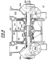
- FIG. 8 is a view similar to FIG. 2 showing another type of prior art liquid ring pump.
- FIG. 9 is a view similar to FIG. 8 showing how the pump of FIG. 8 can be modified in accordance with the present invention.
- FIG. 10 is another view similar to FIG. 8 showing an alternative modification of the pump of FIG. 8 in accordance with this invention.
- FIG. 11 is a view similar to FIG. 1 showing another type of liquid ring pump constructed in accordance with the principles of this invention.
- illustrative prior art liquid ring pump 10 includes stationary housing 12 having annular peripheral wall 14 extending between parallel, spaced, front (or port) and rear plates 16 and 18, respectively.
- Rotor 20 is rotatably mounted in housing 12 by means of drive shaft 22 which extends through rear plate 18 to suitable drive means (not shown) such as an electric motor.
- Annular face seal 23a is provided between shaft 22 and rear plate 18.
- Rotor 20 includes an annular hub 24 connected to drive shaft 22, a plurality of blades 26 extending radially outward from the hub in planes substantially parallel to the axis of drive shaft 22, and a disc-like rear shroud 28 also extending radially outward from the hub in a plane substantially perpendicular to the axis of drive shaft 22 so as to connect the rear portions of all of blades 26.
- Rotor 20 is held on shaft 22 by rotor locking nut 23b.
- Rotor 20 is located eccentrically in housing 12 so that the outer periphery 21 of the rotor is much closer to the inner periphery 15 of annular housing wall 14 near the bottom of the pump than at the top of the pump.
- blades 26 are shown straight in FIGS. 1 and 2, blades 26 could alternatively be curved or hooked either forward or backward relative to the direction of rotor rotation in the manner known to those skilled in the art.
- a quantity of pumping liquid is maintained in housing 12 so that when rotor 20 is rotated as indicated by the arrow 30 in FIG. 1, rotor blades 26 engage the pumping liquid and form it into a recirculating annular ring around the inner periphery 15 of annular housing wall 14.
- the approximate inner boundary or surface of this liquid ring is represented in FIGS. 1 and 2 by the dashed lines 32.
- rotor blades 26 extend much farther into the liquid ring near the bottom of the pump than they do near the top of the pump.
- the inner surface 32 of the liquid ring gradually diverges from rotor hub 24 in the direction of rotor rotation. Accordingly, in that portion of the pump (known as the gas intake zone) the working spaces bounded by adjacent rotor blades 26, rotor hub 24, and the inner surface 32 of the liquid ring gradually increase in volume in the direction of rotor rotation.
- the right-hand side of the pump as viewed in FIG.
- the inner surface 32 of the liquid ring gradually converges toward rotor hub 24 in the direction of rotor rotation. Accordingly, in that portion of the pump (known as the gas compression zone) the working spaces bounded by adjacent rotor blades 26, rotor hub 24, and the inner surface 32 of the liquid ring gradually decrease in volume in the direction of rotor rotation.
- Gas to be pumped is admitted to the intake zone of the pump via intake port 34 in front or port plate 16.
- the gas is supplied to the pump via intake conduit 44 and intake plenum 42. It is pulled into the pump by the expansion of the working spaces in the intake zone. This gas is subsequently compressed by the contraction of the working spaces in the compression zone.
- the compressed gas is then discharged from the pump via discharge port 36 in front or port plate 16.
- the compressed gas is conveyed from the pump via discharge plenum 46 and discharge conduit 48.
- a source of energy loss, and therefore inefficiency, in liquid ring pumps is fluid friction between the recirculating liquid ring and the surface of the stationary housing 12 in contact with the liquid ring.
- this portion of the liquid ring is typically in contact with a housing surface having the shape of a rectangle which is open toward the center of the pump (see especially FIG. 2).
- This open rectangular shape has the largest perimeter at the top of the pump as viewed in FIG. 2, and the smallest perimeter at the bottom of the pump as viewed in that FIG. On the left side of the pump as viewed in FIG.
- the perimeter of this rectangular shape gradually increases from the bottom to the top of the pump. On the right side of the pump as viewed in FIG. 1 the perimeter of this rectangular shape gradually decreases from the top to the bottom of the pump. Described another way, the portion of the liquid ring radially beyond the rotor in any plane which includes the rotor axis in FIGS. 1 and 2 typically occupies a rectangular shaped area in that plane.
- This rectangular shaped area is bounded by the radially outer edges of the rotor blades and the inner surfaces of housing members 14, 16, and 18.
- the size of this rectangular area is smallest at the bottom of FIG. 2, largest at the top of FIG. 2, increasing in size from the bottom to the top on the left of FIG. 1, and decreasing in size from the top to the bottom on the right in FIG. 1.
- the size of this rectangular area in any plane is dictated by the desired size of the adjacent working space in that plane.
- the inner surface of the housing in contact with the liquid ring radially outside the rotor is reshaped so that in each of the above-mentioned planes including the rotor axis the inner surface of the housing is arcuate rather than rectangular. This reduces the area of housing surface in contact with the liquid ring and therefore reduces fluid friction losses in the pump.
- FIGS. 3-5 show one way in which the pump of FIGS. 1 and 2 can be modified in this manner. Except at the extreme bottom of the pump where the inner surface of housing member 14 may remain axially straight and parallel to the rotor axis, in all other planes including the rotor axis the inner surface of housing member 14 is shaped as an axially extending circular arc (e.g., arc 15a at the top of FIG. 3, arc 15b in FIG. 4 which corresponds to the angular position of plane B1 or B2 in FIG. 1, and arc 15c in FIG. 5 which corresponds to the angular position of plane C1 or C2 in FIG. 1). All of these arcs are concave as viewed from rotor 20 outward.
- arc 15a at the top of FIG. 3
- arc 15b in FIG. 4 which corresponds to the angular position of plane B1 or B2 in FIG. 1
- arc 15c in FIG. 5 which corresponds to the angular position of plane C1
- each arc preferably extends axially to but not beyond each axial end of the working portion of the rotor at the radially outer edges 21 of the rotor blades.
- each arc extends axially to but not beyond each of planes D1 and D2 which are substantially perpendicular to the rotor axis and which include the axial ends of the outer edges 21 of the rotor blades.
- a relatively small radius of curvature is used where a relatively large area is needed as at the top of FIG. 3.
- a larger radius of curvature is used as shown in FIG. 4 where a somewhat smaller area is needed, and a still larger radius of curvature is used as shown in FIG. 5 where a still smaller area is needed.
- the radius of curvature may be thought of as extremely large or infinite.
- the angle subtended by the arc is preferably no more than about 180°. If a larger area is needed than can be produced with an arc subtending 180°, then (as shown in FIG. 6) the 180° arc is preferably moved radially outward with tangents 15d in planes D1 and D2 back to the adjacent rotor blade edge.
- FIGS. 3-6 are most preferred because they have the smallest ratio of perimeter to bounded area
- non-circular arcs e.g., arcs of ellipses, ovals, etc., or multiple arcs joined by short, straight tangents
- FIG. 7a illustrates the use of elliptical arcs, the major axis of the ellipse being parallel to the rotor axis.
- FIG. 7b illustrates the use of circular arcuate segments 15e and 15f joined by a straight tangent T. Although tangent T is present in FIG. 7b, the surface is still very predominantly arcuate and is therefore accurately characterized as arcuate.
- inner surface 15 of the housing in contact with the liquid ring be substantially free of discontinuities in the circumferential direction around the pump.
- inner surface 15 is preferably substantially smooth all the way around the pump (like surface 15 in FIG. 1 is smooth all the way around the pump) regardless of the axial location at which surface 15 is considered for this purpose. This means that the transitions from arc to arc circumferentially around the pump are gradual and substantially continuous or smooth.
- circumferential smoothness of surface 15 is best, some slight surface discontinuities in the circumferential direction may be present in some embodiments (see, for example, the embodiment shown in FIG. 11 and discussed in detail below). If present, however, such discontinuities are preferably very small and not prominent enough to cause any significant disturbance in or perturbation of the flow of the adjacent pumping liquid.
- FIG. 8 illustrates a typical prior art double-ended liquid ring pump 110 with frustoconical rather than flat port members.
- rotor 160 is mounted on shaft 180 for rotation inside stationary housing 190.
- Rotor 160 has a hub 162 and radially outwardly extending blades 164.
- the axial ends of blades 164 are interconnected by annular end shrouds 166.
- Blades 164 are also interconnected by annular central shroud 168.
- Rotor 160 has a frustoconical recess concentric with shaft 180 at each axial end.
- a hollow frustoconical port member 140a, 140b fits within each such recess.
- Each port member includes a gas intake conduit 142 and a compressed gas outlet conduit 146.
- conduits in each of port members 140 communicate with other conduits in a respective one of head members 120a and 120b.
- gas intake conduits 122 in head members 120 communicate with conduits 142 in port members 140
- gas outlet conduits 126 in head members 120 communicate with conduits 146 in port members 140.
- Housing 190 is shown as including a radially extending, substantially annular shroud 192 which is radially aligned with the central shroud 168 on rotor 160. Shrouds 168 and/or 192 can be eliminated if desired.
- Pump 110 operates very much like two pumps 10 back to back.
- the use of frustoconical port members in pump 110 helps allow each axial half of the pump to be made axially longer, thereby allowing increased capacity for a given pump diameter as compared to pumps with flat port members.
- FIG. 9 shows one possible way of modifying pump 110 in accordance with this invention.
- the housing surface in contact with the portion of the liquid ring which is radially outside each axial half of rotor 160 is shaped using arcs (e.g., arcs 115a) in the same way that arcs are used in pump 10.
- arcs e.g., arcs 115a
- Each arc extends axially from the associated end shroud 166 to central shroud 168 and is concave as viewed from rotor 160 outward.
- Each arc preferably subtends an angle of no more than about 180°.
- the area bounded by each arc and the adjacent rotor blade outer edge is preferably substantially equal to the area of the rectangular area bounded by that rotor blade edge and housing elements 190 and 192 in the comparable FIG. 8 pump at each angular location around the pump.
- all of the principles discussed above in connection with FIGS. 1-7 apply again to each axial end portion of the FIG. 9 pump.
- the preferred arcs are circular, but arcs of other shapes can be used instead if desired.
- FIG. 10 shows an alternative embodiment of a pump of the type shown in FIG. 9.
- a single continuous arc 115a extends axially from one rotor end shroud 166 to the other such end shroud 166.
- the area bounded by this arc and the adjacent rotor blade outer edges is substantially equal to the area bounded by both arcs 115a and the same rotor blade edges in FIG. 9 at each angular location around the pump.
- FIG. 11 shows a liquid ring pump 210 constructed in accordance with this invention having two intake zones and two compression zones alternating around the pump. Assuming clockwise rotation of rotor 220 inside housing 214, pump 210 has intake zones between planes D2 and A1 and between planes D1 and A2. Pump 210 has compression zones between planes A1 and D1 and between planes A2 and D2. At planes D1 and D2 the inner surface 215 of housing 214 may be as shown at the bottom of the pump in FIG.
- inner surface 215 may be as shown for surface 15 in FIG. 5; at planes B4 and B2, inner surface 215 may be as shown for surface 15 in FIG. 4; and at planes A1 and A2, surface 215 may be as shown for surface 15 at the top of FIG. 3. Thereafter, surface 215 gradually becomes less axially arcuate.
- inner surface 215 may again be as shown for surface .15 in FIG.
- Pump 210 illustrates the possibility that the inner surface 215 may have slight discontinuities in the circumferential direction.
- slight circumferential surface discontinuities exist at points X in pump 210, although they are so slight, that they may be difficult to see in FIG. 11.
- surface 215 may still be accurately characterized as being substantially free of discontinuities in the circumferential direction all the way around the pump. As mentioned above, these discontinuities are so small that they do not cause any significant disturbance in or perturbation of the adjacent pumping liquid flow.
Landscapes
- Engineering & Computer Science (AREA)
- Mechanical Engineering (AREA)
- General Engineering & Computer Science (AREA)
- Structures Of Non-Positive Displacement Pumps (AREA)
- Rotary Pumps (AREA)
Description
- This invention relates to liquid ring pumps, and more particularly to liquid ring pumps in which the inner surfaces of the housings are shaped to reduce fluid friction losses in the pumps.
- Liquid ring pumps are well known as shown, for example, by Sommer U.S. patent 1,525,332 and Haavik U.S. patent 4,613,283. Russian inventor's certificate 529,295 points out that fluid friction in such pumps can be reduced by making the housing and turbine wheel of trapezoidal shape in axial section. According to this reference, by shaping the pump in this way the area of the housing surface contacted by the liquid is reduced, thereby reducing hydrodynamic loss in the pump.
- The pump design shown in the above-mentioned Russian inventor's certificate results in several parts having very complex shapes. For example, the central housing element varies in axial length around the pump. As a consequence of this aspect of the shape of the central element, the faces of the end housing elements which abut the central element do not lie in planes perpendicular to the rotor axis. The pump of the Russian inventor's certificate would therefore be relatively difficult and expensive to make. In addition, while the trapezoidal shape shown in the Russian inventor's certificate may reduce hydrodynamic loss in the pump to some degree, there is a need for further reduction in such loss.
- WO-A-91/19904 describes a liquid ring pump in which the inner annular surface of the housing is curved to accommodate the liquid ring. However, the curved inner annular surface includes several discontinuities which contribute to the overall friction losses of the pump.
- DE-B-1014282 describes a liquid ring pump which includes an eccentric trench for accommodating the liquid ring. The trench is of a generally trapezoidal cross section, with slightly rounded edges, and this irregular shape will also lead to relatively high hydrodynamic losses in the pump.
- In view of the foregoing, it is an object of this invention to provide improved liquid ring pumps.
- It is a more particular object of this invention to provide liquid ring pumps with reduced hydrodynamic loss due to contact between the recirculating liquid ring in the pump and the stationary housing of the pump.
- According to a first aspect of the invention there is provided a liquid ring pump having a rotor rotatably mounted about a rotor axis in an annular housing for forming a quantity of liquid in the housing into a recirculating annular ring inside the annular inner surface of the housing such that the liquid ring moves radially outward from the rotor axis adjacent a gas intake zone of the pump and moves radially inward again adjacent a gas compression zone of the pump, said rotor having a plurality of circumferentially spaced, axially extending blades, the opposite axial ends of the radially outer edges of said blades lying in axially spaced first and second planes which are substantially perpendicular to said rotor axis, said annular inner surface of said housing being formed so that the intersection between said annular inner surface and substantially any plane in which said rotor axis lies is an arc that is concave as viewed from said rotor axis outward, and said annular inner surface being substantially free of discontinuities in the circumferential direction all the way around said pump characterised in that said arc extends axially substantially the entire distance between but not substantially beyond said first and second planes, the radius of curvature of said arc increasing in the direction of rotor -rotation adjacent the gas compression zone. According to a second aspect of the invention there is provided a liquid ring pump having a rotor rotatably mounted in an annular housing for forming a quantity of liquid in the housing into a recirculating annular ring inside the annular inner surface of the housing such that the liquid ring moves radially outward from the rotor axis adjacent a gas intake zone of the pump and moves radially inward again adjacent a gas compression zone of the pump, said rotor having a plurality of circumferentially spaced, axially extending blades, the opposite axial ends of the radial outer edges of said blades lying in axially spaced first and second planes which are substantially perpendicular to said rotor axis, characterised in that the annular inner surface of said housing is formed so that the intersection between said annular inner surface and substantially any plane which includes said rotor axis is a pair of axially adjacent, axially extending arcs joined at an intermediate cusp-like region, each said arc being concave as viewed from said rotor axis outward, the end of each arc which is remote from said cusp-like region extending axially to but not substantially beyond a respective one of said first and second planes, the intermediate cusp-like regions of all of said pairs of arcs lying approximately in a third plane which is substantially perpendicular to said rotor axis, the radius of curvature of each said arc increasing in the direction of rotor rotation adjacent the gas compression zone, and said annular inner surface being substantially free of discontinuities in the circumferential direction all the way around said pump. While other arcuate shapes (such as arcs of ellipses, ovals, etc.) can be employed in accordance with the invention, in the most preferred embodiments the arcs are circular because, of all geometric shapes, circles have the smallest ratio of circumference to area. Most preferably the inner surface of the housing in contact with the portion of the liquid ring which is radially outside the rotor does not extend axially beyond the planes perpendicular to the rotor axis which include the axial ends of the radially outer edges of the rotor blades. Also most preferably each arc subtends an angle of no more than approximately 180°, and each arc extends to each of the above-mentioned planes perpendicular to the rotor axis. However, if the rotor is double-ended with a center shroud, the center shroud defines a third plane perpendicular to the rotor axis, and each arc may either extend without axial discontinuity through that plane, or the inner surface of the housing may have a cusp in the third plane.
- Further features of the invention, its nature and various advantages will be more apparent from the accompanying drawings and the following detailed description of the preferred embodiments.
- FIG. 1 is a simplified cross sectional view of an illustrative conventional liquid ring pump. FIG. 1 is taken along the line 1-1 in FIG. 2.
- FIG. 2 is a sectional view taken along the line 2-2 in FIG. 1.
- FIG. 3 is a view similar to FIG. 2 showing an illustrative embodiment of the present invention.
- FIG. 4 is a view similar to a portion of FIG. 3 but taken at another angular location in the pump of FIG. 3 (i.e., at an angular location comparable to the one indicated by the line B1 or the line B2 in FIG. 1).
- FIG. 5 is another view similar to a portion of FIG. 3 but taken at still another angular location in the pump of FIG. 3 (i.e., at an angular location comparable to the one indicated by the line C1 or the line C2 in FIG. 1).
- FIG. 6 is a view similar to a portion of FIG. 3 showing an alternative embodiment of the invention.
- FIG. 7a is a view similar to a portion of FIG. 3 showing another alternative embodiment of the invention.
- FIG. 7b is another view similar to a portion of FIG. 3 showing still another alternative embodiment of the invention.
- FIG. 8 is a view similar to FIG. 2 showing another type of prior art liquid ring pump.
- FIG. 9 is a view similar to FIG. 8 showing how the pump of FIG. 8 can be modified in accordance with the present invention.
- FIG. 10 is another view similar to FIG. 8 showing an alternative modification of the pump of FIG. 8 in accordance with this invention.
- FIG. 11 is a view similar to FIG. 1 showing another type of liquid ring pump constructed in accordance with the principles of this invention.
- Although the principles of this invention are equally applicable to liquid ring pumps having any number of intake and compression zones alternating in the circumferential direction around the pump, the invention will first be described in the context of pumps having only one intake zone and one compression zone in the circumferential direction. Similarly, although the invention is applicable to pumps having many different port configurations (e.g., ports through flat end plates or ports through frustoconical or cylindrical port members), the invention will be fully understood from the following discussion of pumps with two exemplary types of port structures. The invention is also applicable to any stage or stages of multistage pumps (i.e., pumps which discharge gas from one stage to the intake of another stage), but again the invention will be fully understood from the following explanation of its application to single-stage pumps.
- As shown in FIGS. 1 and 2, illustrative prior art
liquid ring pump 10 includesstationary housing 12 having annularperipheral wall 14 extending between parallel, spaced, front (or port) andrear plates Rotor 20 is rotatably mounted inhousing 12 by means ofdrive shaft 22 which extends throughrear plate 18 to suitable drive means (not shown) such as an electric motor. Annular face seal 23a is provided betweenshaft 22 andrear plate 18. -
Rotor 20 includes anannular hub 24 connected to driveshaft 22, a plurality ofblades 26 extending radially outward from the hub in planes substantially parallel to the axis ofdrive shaft 22, and a disc-likerear shroud 28 also extending radially outward from the hub in a plane substantially perpendicular to the axis ofdrive shaft 22 so as to connect the rear portions of all ofblades 26.Rotor 20 is held onshaft 22 byrotor locking nut 23b.Rotor 20 is located eccentrically inhousing 12 so that theouter periphery 21 of the rotor is much closer to theinner periphery 15 ofannular housing wall 14 near the bottom of the pump than at the top of the pump. Althoughblades 26 are shown straight in FIGS. 1 and 2,blades 26 could alternatively be curved or hooked either forward or backward relative to the direction of rotor rotation in the manner known to those skilled in the art. - A quantity of pumping liquid is maintained in
housing 12 so that whenrotor 20 is rotated as indicated by thearrow 30 in FIG. 1,rotor blades 26 engage the pumping liquid and form it into a recirculating annular ring around theinner periphery 15 ofannular housing wall 14. The approximate inner boundary or surface of this liquid ring is represented in FIGS. 1 and 2 by thedashed lines 32. - As best seen in FIG. 1, because
rotor 20 is mounted eccentrically relative tohousing wall 14, and hence is also eccentric to the liquid ring,rotor blades 26 extend much farther into the liquid ring near the bottom of the pump than they do near the top of the pump. On the left-hand side of the pump as viewed in FIG. 1, theinner surface 32 of the liquid ring gradually diverges fromrotor hub 24 in the direction of rotor rotation. Accordingly, in that portion of the pump (known as the gas intake zone) the working spaces bounded byadjacent rotor blades 26,rotor hub 24, and theinner surface 32 of the liquid ring gradually increase in volume in the direction of rotor rotation. On the right-hand side of the pump as viewed in FIG. 1, theinner surface 32 of the liquid ring gradually converges towardrotor hub 24 in the direction of rotor rotation. Accordingly, in that portion of the pump (known as the gas compression zone) the working spaces bounded byadjacent rotor blades 26,rotor hub 24, and theinner surface 32 of the liquid ring gradually decrease in volume in the direction of rotor rotation. - Gas to be pumped is admitted to the intake zone of the pump via
intake port 34 in front orport plate 16. The gas is supplied to the pump viaintake conduit 44 andintake plenum 42. It is pulled into the pump by the expansion of the working spaces in the intake zone. This gas is subsequently compressed by the contraction of the working spaces in the compression zone. The compressed gas is then discharged from the pump viadischarge port 36 in front orport plate 16. The compressed gas is conveyed from the pump viadischarge plenum 46 anddischarge conduit 48. - A source of energy loss, and therefore inefficiency, in liquid ring pumps is fluid friction between the recirculating liquid ring and the surface of the
stationary housing 12 in contact with the liquid ring. Considering only the portion of the liquid ring which is radially beyond the radially outer edges ofblades 26 in the illustrative pump of FIGS. 1 and 2, this portion of the liquid ring is typically in contact with a housing surface having the shape of a rectangle which is open toward the center of the pump (see especially FIG. 2). This open rectangular shape has the largest perimeter at the top of the pump as viewed in FIG. 2, and the smallest perimeter at the bottom of the pump as viewed in that FIG. On the left side of the pump as viewed in FIG. 1, the perimeter of this rectangular shape gradually increases from the bottom to the top of the pump. On the right side of the pump as viewed in FIG. 1 the perimeter of this rectangular shape gradually decreases from the top to the bottom of the pump. Described another way, the portion of the liquid ring radially beyond the rotor in any plane which includes the rotor axis in FIGS. 1 and 2 typically occupies a rectangular shaped area in that plane. This rectangular shaped area is bounded by the radially outer edges of the rotor blades and the inner surfaces ofhousing members - The above-described rectangular-shaped areas are relatively inefficient in terms of ratio of area to perimeter. In other words, because these shapes are rectangular, they have a relatively high perimeter for a given area. This in turn means that for a given volume of liquid outside the rotor, a relatively large area of stationary housing surface is in contact with the liquid. Fluid friction loss is therefore relatively high.
- In accordance with the present invention, the inner surface of the housing in contact with the liquid ring radially outside the rotor is reshaped so that in each of the above-mentioned planes including the rotor axis the inner surface of the housing is arcuate rather than rectangular. This reduces the area of housing surface in contact with the liquid ring and therefore reduces fluid friction losses in the pump.
- FIGS. 3-5 show one way in which the pump of FIGS. 1 and 2 can be modified in this manner. Except at the extreme bottom of the pump where the inner surface of
housing member 14 may remain axially straight and parallel to the rotor axis, in all other planes including the rotor axis the inner surface ofhousing member 14 is shaped as an axially extending circular arc (e.g., arc 15a at the top of FIG. 3,arc 15b in FIG. 4 which corresponds to the angular position of plane B1 or B2 in FIG. 1, andarc 15c in FIG. 5 which corresponds to the angular position of plane C1 or C2 in FIG. 1). All of these arcs are concave as viewed fromrotor 20 outward. (Although in the particular embodiment shown in FIG. 3 the inner surface ofhousing member 14 is axially straight and parallel to the rotor axis at the bottom of the pump, in other embodiments even this portion of the housing inner surface may be slightly curved in the same general way as other portions of that surface.) Each arc preferably extends axially to but not beyond each axial end of the working portion of the rotor at the radiallyouter edges 21 of the rotor blades. Thus each arc extends axially to but not beyond each of planes D1 and D2 which are substantially perpendicular to the rotor axis and which include the axial ends of theouter edges 21 of the rotor blades. At each angular location around the pump the area in the plane which includes the rotor axis and which is bounded by (1) the above-mentioned arc, (2) the adjacent outer rotor blade edges 21, and (3) (if necessary) planes D1 and D2 is preferably approximately equal to the area in the liquid ring outside the rotor at that same angular location in the comparable prior art pump (FIGS. 1 and 2). Thus the same amount of liquid can flow outside the rotor at each location around both the old and new pumps so the shape of the inner surface of the liquid ring is substantially unaltered by this invention. Equalizing the above-mentioned areas in comparable new and old pumps is therefore one way in which the radius of the arc at each location around the new pumps can be determined. Comparing FIGS. 3-5 it will be noted that a relatively small radius of curvature is used where a relatively large area is needed as at the top of FIG. 3. A larger radius of curvature is used as shown in FIG. 4 where a somewhat smaller area is needed, and a still larger radius of curvature is used as shown in FIG. 5 where a still smaller area is needed. In the limit, where the smallest area is needed at the bottom of FIG. 3, the radius of curvature may be thought of as extremely large or infinite. - Just as the radius of curvature increases as the area bounded in part by the above-mentioned arcs decreases, so also the angle subtended by the arc decreases as the area decreases. However, to avoid a re-entrant or keyhole shape, the angle subtended by the arc is preferably no more than about 180°. If a larger area is needed than can be produced with an arc subtending 180°, then (as shown in FIG. 6) the 180° arc is preferably moved radially outward with
tangents 15d in planes D1 and D2 back to the adjacent rotor blade edge. - While the circular arcs shown in FIGS. 3-6 are most preferred because they have the smallest ratio of perimeter to bounded area, non-circular arcs (e.g., arcs of ellipses, ovals, etc., or multiple arcs joined by short, straight tangents) can also be employed in accordance with this invention. For example, FIG. 7a illustrates the use of elliptical arcs, the major axis of the ellipse being parallel to the rotor axis. FIG. 7b illustrates the use of circular
arcuate segments - It is preferred in all cases that the
inner surface 15 of the housing in contact with the liquid ring be substantially free of discontinuities in the circumferential direction around the pump. Thusinner surface 15 is preferably substantially smooth all the way around the pump (likesurface 15 in FIG. 1 is smooth all the way around the pump) regardless of the axial location at which surface 15 is considered for this purpose. This means that the transitions from arc to arc circumferentially around the pump are gradual and substantially continuous or smooth. Although it is believed that circumferential smoothness ofsurface 15 is best, some slight surface discontinuities in the circumferential direction may be present in some embodiments (see, for example, the embodiment shown in FIG. 11 and discussed in detail below). If present, however, such discontinuities are preferably very small and not prominent enough to cause any significant disturbance in or perturbation of the flow of the adjacent pumping liquid. - FIG. 8 illustrates a typical prior art double-ended
liquid ring pump 110 with frustoconical rather than flat port members. Inpump 110rotor 160 is mounted onshaft 180 for rotation insidestationary housing 190.Rotor 160 has ahub 162 and radially outwardly extendingblades 164. The axial ends ofblades 164 are interconnected by annular end shrouds 166.Blades 164 are also interconnected by annularcentral shroud 168.Rotor 160 has a frustoconical recess concentric withshaft 180 at each axial end. A hollowfrustoconical port member head members Housing 190 is shown as including a radially extending, substantiallyannular shroud 192 which is radially aligned with thecentral shroud 168 onrotor 160.Shrouds 168 and/or 192 can be eliminated if desired. -
Pump 110 operates very much like twopumps 10 back to back. The use of frustoconical port members inpump 110 helps allow each axial half of the pump to be made axially longer, thereby allowing increased capacity for a given pump diameter as compared to pumps with flat port members. - FIG. 9 shows one possible way of modifying
pump 110 in accordance with this invention. In FIG. 9 the housing surface in contact with the portion of the liquid ring which is radially outside each axial half ofrotor 160 is shaped using arcs (e.g., arcs 115a) in the same way that arcs are used inpump 10. Each arc extends axially from the associatedend shroud 166 tocentral shroud 168 and is concave as viewed fromrotor 160 outward. Each arc preferably subtends an angle of no more than about 180°. The area bounded by each arc and the adjacent rotor blade outer edge is preferably substantially equal to the area of the rectangular area bounded by that rotor blade edge andhousing elements - FIG. 10 shows an alternative embodiment of a pump of the type shown in FIG. 9. In FIG. 10 a single
continuous arc 115a extends axially from onerotor end shroud 166 to the othersuch end shroud 166. The area bounded by this arc and the adjacent rotor blade outer edges is substantially equal to the area bounded by botharcs 115a and the same rotor blade edges in FIG. 9 at each angular location around the pump. Again, all of the same principles discussed above in connection with the other embodiments apply to the embodiment shown in FIG. 10. - All of the embodiments discussed above have one intake and one compression stroke per cycle of rotor revolution. It is well known, however, that liquid ring pumps can have more than one operating cycle per rotor revolution. For example, FIG. 11 shows a
liquid ring pump 210 constructed in accordance with this invention having two intake zones and two compression zones alternating around the pump. Assuming clockwise rotation of rotor 220 insidehousing 214, pump 210 has intake zones between planes D2 and A1 and between planes D1 and A2.Pump 210 has compression zones between planes A1 and D1 and between planes A2 and D2. At planes D1 and D2 theinner surface 215 ofhousing 214 may be as shown at the bottom of the pump in FIG. 3 (i.e., axially straight and parallel to the axis ofrotor shaft 222, or at least approximately as thus described). As one progresses from each of these planes into the succeeding intake zone,surface 215 gradually becomes increasingly axially arcuate as described above for the other embodiments. For example, at planes C4 and C2,inner surface 215 may be as shown forsurface 15 in FIG. 5; at planes B4 and B2,inner surface 215 may be as shown forsurface 15 in FIG. 4; and at planes A1 and A2,surface 215 may be as shown forsurface 15 at the top of FIG. 3. Thereafter,surface 215 gradually becomes less axially arcuate. Thus at planes B1 and B3,inner surface 215 may again be as shown for surface .15 in FIG. 4; and at planes C1 and C3,surface 215 may again be as shown forsurface 15 in FIG. 5. All of the principles discussed above in connection with the previous embodiments are again applicable to pump 210. The only difference is that instead of having one cycle of operation per rotor revolution, pump 210 has two identical cycles of operation per revolution. -
Pump 210 illustrates the possibility that theinner surface 215 may have slight discontinuities in the circumferential direction. For example, slight circumferential surface discontinuities exist at points X inpump 210, although they are so slight, that they may be difficult to see in FIG. 11. Hence, even though slight discontinuities X are present inpump 210,surface 215 may still be accurately characterized as being substantially free of discontinuities in the circumferential direction all the way around the pump. As mentioned above, these discontinuities are so small that they do not cause any significant disturbance in or perturbation of the adjacent pumping liquid flow. - It will be understood that the foregoing is merely illustrative of the principles of this invention, and that various modifications can be made by those skilled in the art without departing from the scope of the invention. For example, although all of the depicted embodiments are single-stage pumps, it will be readily apparent to those skilled in the art that the invention is equally applicable to any stage or stages of multistage pumps.
Claims (9)
- A liquid ring pump (10,110,210) having a rotor (20,160,220) rotatably mounted about a rotor axis in an annular housing (12,120,214) for forming a quantity of liquid in the housing (12,120,214) into a recirculating annular ring inside the annular inner surface (15,115,215) of the housing (12,120,214) such that the liquid ring moves radially outward from the rotor axis adjacent a gas intake zone of the pump and moves radially inward again adjacent a gas compression zone of the pump, said rotor having a plurality of circumferentially spaced, axially extending blades (26,164), the opposite axial ends of the radially outer edges of said blades (26,164) lying in axially spaced first and second planes (D1,D2) which are substantially perpendicular to said rotor axis, said annular inner surface (15,115,215) of said housing (12,120,214) being formed so that the intersection between said annular inner surface (15,115,215) and substantially any plane in which said rotor axis lies is an arc that is concave as viewed from said rotor axis outward, and said annular inner surface (15,115,215) being substantially free of discontinuities in the circumferential direction all the way around said pump (10,110,210) characterised in that said arc extends axially substantially the entire distance between but not substantially beyond said first and second planes (D1,D2), the radius of curvature of said arc increasing in the direction of rotor rotation adjacent the gas compression zone.
- The pump defined in claim 1 wherein each said arc is substantially circular.
- The pump defined in claim 1 or claim 2 wherein each said arc subtends an angle of no more than 180°.
- The pump defined in claim 3 wherein each said arc is intercepted by each of said first and second planes (D1,D2) immediately adjacent to the radially outer edges of said blades (26).
- A liquid ring pump (110,210) having a rotor (160,220) rotatably mounted in an annular housing (120,214) for forming a quantity of liquid in the housing into a recirculating annular ring inside the annular inner surface of the housing (120,214) such that the liquid ring moves radially outward from the rotor axis adjacent a gas intake zone of the pump and moves radially inward again adjacent a gas compression zone of the pump, said rotor having a plurality of circumferentially spaced, axially extending blades (164), the opposite axial ends of the radial outer edges of said blades (164) lying in axially spaced first and second planes which are substantially perpendicular to said rotor axis, characterised in that the annular inner surface (115,215) of said housing (120,214) is formed so that the intersection between said annular inner surface (115,215) and substantially any plane which includes said rotor axis is a pair of axially adjacent, axially extending arcs joined at an intermediate cusp-like region, each said arc being concave as viewed from said rotor axis outward, the end of each arc which is remote from said cusp-like region extending axially to but not substantially beyond a respective one of said first and second planes, the intermediate cusp-like regions of all of said pairs of arcs lying approximately in a third plane which is substantially perpendicular to said rotor axis, the radius of curvature of each said arc increasing in the direction of rotor rotation adjacent the gas compression zone, and said annular inner surface being substantially free of discontinuities in the circumferential direction all the way around said pump.
- The pump defined in claim 5 wherein said rotor (160) is axially partitioned by an annular shroud (168) disposed in said third plane.
- The pump defined in claim 5 or claim 6 wherein each said arc is substantially circular.
- The pump defined in any one of claims 5 to 7 wherein each said arc subtends an angle of no more than 180°.
- The pump defined in claim 8 wherein each said arc is intercepted by two of said first through third planes immediately adjacent to the radially outer edges of said blades (164).
Applications Claiming Priority (2)
| Application Number | Priority Date | Filing Date | Title |
|---|---|---|---|
| US865448 | 1986-05-21 | ||
| US07/865,448 US5213479A (en) | 1992-04-09 | 1992-04-09 | Liquid ring pumps with improved housing shapes |
Publications (2)
| Publication Number | Publication Date |
|---|---|
| EP0565232A1 EP0565232A1 (en) | 1993-10-13 |
| EP0565232B1 true EP0565232B1 (en) | 1996-07-03 |
Family
ID=25345533
Family Applications (1)
| Application Number | Title | Priority Date | Filing Date |
|---|---|---|---|
| EP93301649A Expired - Lifetime EP0565232B1 (en) | 1992-04-09 | 1993-03-04 | Liquid ring pumps with improved housing shapes |
Country Status (10)
| Country | Link |
|---|---|
| US (1) | US5213479A (en) |
| EP (1) | EP0565232B1 (en) |
| JP (1) | JPH0642478A (en) |
| KR (1) | KR930021948A (en) |
| BR (1) | BR9301503A (en) |
| CA (1) | CA2090184A1 (en) |
| DE (1) | DE69303411T2 (en) |
| FI (1) | FI105284B (en) |
| GB (1) | GB2265944B (en) |
| ZA (1) | ZA931488B (en) |
Cited By (1)
| Publication number | Priority date | Publication date | Assignee | Title |
|---|---|---|---|---|
| EP2587065A1 (en) | 2011-10-26 | 2013-05-01 | NSB Gas Processing AG | Liquid ring compressor |
Families Citing this family (14)
| Publication number | Priority date | Publication date | Assignee | Title |
|---|---|---|---|---|
| CA2131081C (en) * | 1993-09-16 | 2004-01-20 | Udo Segebrecht | Liquid ring gas pump |
| US5507625A (en) * | 1995-04-14 | 1996-04-16 | The Nash Engineering Company | Liquid ring pumps |
| DE19529242A1 (en) * | 1995-08-09 | 1997-02-13 | Basf Ag | Phosphoric acid esters |
| US5653582A (en) * | 1995-09-26 | 1997-08-05 | The Nash Engineering Company | Fluid bearing pad arrangement for liquid ring pump systems |
| DE19653746C2 (en) * | 1996-12-20 | 1999-05-06 | Siemens Ag | Impeller for a liquid ring machine |
| US5961295A (en) * | 1997-07-03 | 1999-10-05 | The Nash Engineering Company | Mixed flow liquid ring pumps |
| US6318970B1 (en) | 1998-03-12 | 2001-11-20 | Micralyne Inc. | Fluidic devices |
| US6976590B2 (en) | 2002-06-24 | 2005-12-20 | Cytonome, Inc. | Method and apparatus for sorting particles |
| US9943847B2 (en) | 2002-04-17 | 2018-04-17 | Cytonome/St, Llc | Microfluidic system including a bubble valve for regulating fluid flow through a microchannel |
| US20070065808A1 (en) * | 2002-04-17 | 2007-03-22 | Cytonome, Inc. | Method and apparatus for sorting particles |
| US9260693B2 (en) | 2004-12-03 | 2016-02-16 | Cytonome/St, Llc | Actuation of parallel microfluidic arrays |
| US20110194950A1 (en) * | 2010-02-10 | 2011-08-11 | Shenoi Ramesh B | Efficiency improvements for liquid ring pumps |
| US10041367B2 (en) | 2013-12-12 | 2018-08-07 | General Electric Company | Axially faced seal system |
| KR102097333B1 (en) | 2014-08-05 | 2020-04-06 | 삼성전기주식회사 | Multi-layer ceramic capacitor |
Family Cites Families (13)
| Publication number | Priority date | Publication date | Assignee | Title |
|---|---|---|---|---|
| US1525332A (en) * | 1922-08-10 | 1925-02-03 | American Steam Pump Company | Centrifugal fluid vacuum pump |
| US2092740A (en) * | 1935-11-16 | 1937-09-07 | Maschf Gebr Stork & Co N V | Rotary pump |
| FR813235A (en) * | 1935-11-16 | 1937-05-28 | Machf Gebr Stork & Co N V | Improvements to rotary pumps |
| GB464089A (en) * | 1935-11-16 | 1937-04-12 | Machf Gebr Stork & Co N V | Improvements in and relating to centrifugal pumps |
| US2368528A (en) * | 1941-02-01 | 1945-01-30 | Edwards Miles Lowell | Pump |
| CH257507A (en) * | 1946-05-15 | 1948-10-15 | Westinghouse Electric Corp | Sealing device for a rotating shaft, in particular a gas compressor. |
| DE966700C (en) * | 1954-09-26 | 1957-09-05 | Siemens Ag | Two-stage single-wheel liquid ring pump |
| DE1014282B (en) * | 1956-09-17 | 1957-08-22 | Siemen & Hinsch Gmbh | Multi-stage single-wheel liquid ring pump |
| SU529295A1 (en) * | 1975-06-03 | 1976-09-25 | Предприятие П/Я А-3605 | Liquid ring machine " |
| DE3313446A1 (en) * | 1983-04-13 | 1984-10-18 | Friedrich 8541 Röttenbach Schweinfurter | Liquid ring pump |
| US4747752A (en) * | 1987-04-20 | 1988-05-31 | Somarakis, Inc. | Sealing and dynamic operation of a liquid ring pump |
| WO1991019904A1 (en) * | 1990-06-18 | 1991-12-26 | Sports Marine International Pty. Ltd. | Rotary fluid pumping apparatus |
| US5078573A (en) * | 1990-09-07 | 1992-01-07 | A. Ahlstrom Corporation | Liquid ring pump having tapered blades and housing |
-
1992
- 1992-04-09 US US07/865,448 patent/US5213479A/en not_active Expired - Fee Related
-
1993
- 1993-02-23 CA CA002090184A patent/CA2090184A1/en not_active Abandoned
- 1993-03-02 ZA ZA931488A patent/ZA931488B/en unknown
- 1993-03-04 EP EP93301649A patent/EP0565232B1/en not_active Expired - Lifetime
- 1993-03-04 DE DE69303411T patent/DE69303411T2/en not_active Expired - Fee Related
- 1993-03-04 GB GB9304423A patent/GB2265944B/en not_active Expired - Fee Related
- 1993-03-26 JP JP5067998A patent/JPH0642478A/en active Pending
- 1993-04-07 FI FI931577A patent/FI105284B/en active
- 1993-04-08 KR KR1019930005865A patent/KR930021948A/en not_active IP Right Cessation
- 1993-04-12 BR BR9301503A patent/BR9301503A/en not_active IP Right Cessation
Cited By (3)
| Publication number | Priority date | Publication date | Assignee | Title |
|---|---|---|---|---|
| EP2587065A1 (en) | 2011-10-26 | 2013-05-01 | NSB Gas Processing AG | Liquid ring compressor |
| WO2013060754A2 (en) | 2011-10-26 | 2013-05-02 | Nsb Gas Processing Ag | Liquid ring compressor |
| WO2013060754A3 (en) * | 2011-10-26 | 2013-09-26 | Nsb Gas Processing Ag | Liquid ring compressor |
Also Published As
| Publication number | Publication date |
|---|---|
| JPH0642478A (en) | 1994-02-15 |
| GB9304423D0 (en) | 1993-04-21 |
| EP0565232A1 (en) | 1993-10-13 |
| BR9301503A (en) | 1993-10-13 |
| DE69303411T2 (en) | 1997-02-27 |
| FI105284B (en) | 2000-07-14 |
| DE69303411D1 (en) | 1996-08-08 |
| CA2090184A1 (en) | 1993-10-10 |
| FI931577A0 (en) | 1993-04-07 |
| FI931577A (en) | 1993-10-10 |
| ZA931488B (en) | 1993-09-30 |
| KR930021948A (en) | 1993-11-23 |
| US5213479A (en) | 1993-05-25 |
| GB2265944A (en) | 1993-10-13 |
| GB2265944B (en) | 1996-01-03 |
Similar Documents
| Publication | Publication Date | Title |
|---|---|---|
| EP0565232B1 (en) | Liquid ring pumps with improved housing shapes | |
| EP0526965B1 (en) | Compressor casings for turbochargers | |
| CA1240557A (en) | Impeller | |
| EP1507977B1 (en) | Discrete passage diffuser | |
| US2165808A (en) | Pump rotor | |
| US3860360A (en) | Diffuser for a centrifugal compressor | |
| EP0770781A1 (en) | Turbomolecular vacuum pumps | |
| EP0515633B1 (en) | Regenerative pump | |
| CN100387850C (en) | Centrifugal pump with configured volute | |
| US4480973A (en) | Vane compressor provided with endless camming surface minimizing torque fluctuations | |
| EP0886070A1 (en) | Centrifugal compressor and diffuser for the centrifugal compressor | |
| US3782850A (en) | Energy transfer machine | |
| JPH01315687A (en) | Annular diaphragm pump | |
| US5558490A (en) | Liquid pump | |
| KR100324839B1 (en) | Vortex Pump | |
| US4834612A (en) | In a pump wheel of a side-channel fuel pump | |
| BG64490B1 (en) | Twin helical rotors for installation in displacement machines for compressibble media | |
| US5209630A (en) | Pump impeller | |
| US5265996A (en) | Regenerative pump with improved suction | |
| US3289923A (en) | Multi-stage pump | |
| US4712987A (en) | Vane compressor provided with endless camming surface minimizing torque fluctuations | |
| US4500253A (en) | Side-channel pump | |
| US20080056886A1 (en) | Vacuum pumps with improved pumping channel cross sections | |
| US4599058A (en) | Vane slots for a fluid power converter | |
| US5375980A (en) | Housing configuration for helical bladed fluid ring pump |
Legal Events
| Date | Code | Title | Description |
|---|---|---|---|
| PUAI | Public reference made under article 153(3) epc to a published international application that has entered the european phase |
Free format text: ORIGINAL CODE: 0009012 |
|
| AK | Designated contracting states |
Kind code of ref document: A1 Designated state(s): DE FR SE |
|
| 17P | Request for examination filed |
Effective date: 19940304 |
|
| 17Q | First examination report despatched |
Effective date: 19950323 |
|
| GRAH | Despatch of communication of intention to grant a patent |
Free format text: ORIGINAL CODE: EPIDOS IGRA |
|
| GRAH | Despatch of communication of intention to grant a patent |
Free format text: ORIGINAL CODE: EPIDOS IGRA |
|
| GRAA | (expected) grant |
Free format text: ORIGINAL CODE: 0009210 |
|
| AK | Designated contracting states |
Kind code of ref document: B1 Designated state(s): DE FR SE |
|
| REF | Corresponds to: |
Ref document number: 69303411 Country of ref document: DE Date of ref document: 19960808 |
|
| ET | Fr: translation filed | ||
| PLBE | No opposition filed within time limit |
Free format text: ORIGINAL CODE: 0009261 |
|
| STAA | Information on the status of an ep patent application or granted ep patent |
Free format text: STATUS: NO OPPOSITION FILED WITHIN TIME LIMIT |
|
| 26N | No opposition filed | ||
| PGFP | Annual fee paid to national office [announced via postgrant information from national office to epo] |
Ref country code: FR Payment date: 19980209 Year of fee payment: 6 |
|
| PG25 | Lapsed in a contracting state [announced via postgrant information from national office to epo] |
Ref country code: FR Free format text: LAPSE BECAUSE OF NON-PAYMENT OF DUE FEES Effective date: 19991130 |
|
| REG | Reference to a national code |
Ref country code: FR Ref legal event code: ST |
|
| PGFP | Annual fee paid to national office [announced via postgrant information from national office to epo] |
Ref country code: SE Payment date: 20000321 Year of fee payment: 8 |
|
| PGFP | Annual fee paid to national office [announced via postgrant information from national office to epo] |
Ref country code: DE Payment date: 20000324 Year of fee payment: 8 |
|
| PG25 | Lapsed in a contracting state [announced via postgrant information from national office to epo] |
Ref country code: SE Free format text: LAPSE BECAUSE OF NON-PAYMENT OF DUE FEES Effective date: 20010305 |
|
| EUG | Se: european patent has lapsed |
Ref document number: 93301649.5 |
|
| PG25 | Lapsed in a contracting state [announced via postgrant information from national office to epo] |
Ref country code: DE Free format text: LAPSE BECAUSE OF NON-PAYMENT OF DUE FEES Effective date: 20020101 |