EP2584786A2 - Bildübertragungsvorrichtung und -verfahren - Google Patents
Bildübertragungsvorrichtung und -verfahren Download PDFInfo
- Publication number
- EP2584786A2 EP2584786A2 EP20120161112 EP12161112A EP2584786A2 EP 2584786 A2 EP2584786 A2 EP 2584786A2 EP 20120161112 EP20120161112 EP 20120161112 EP 12161112 A EP12161112 A EP 12161112A EP 2584786 A2 EP2584786 A2 EP 2584786A2
- Authority
- EP
- European Patent Office
- Prior art keywords
- signal
- images
- display
- output
- operable
- Prior art date
- Legal status (The legal status is an assumption and is not a legal conclusion. Google has not performed a legal analysis and makes no representation as to the accuracy of the status listed.)
- Granted
Links
Images


Classifications
-
- H—ELECTRICITY
- H04—ELECTRIC COMMUNICATION TECHNIQUE
- H04N—PICTORIAL COMMUNICATION, e.g. TELEVISION
- H04N13/00—Stereoscopic video systems; Multi-view video systems; Details thereof
- H04N13/10—Processing, recording or transmission of stereoscopic or multi-view image signals
- H04N13/106—Processing image signals
- H04N13/139—Format conversion, e.g. of frame-rate or size
-
- A—HUMAN NECESSITIES
- A63—SPORTS; GAMES; AMUSEMENTS
- A63F—CARD, BOARD, OR ROULETTE GAMES; INDOOR GAMES USING SMALL MOVING PLAYING BODIES; VIDEO GAMES; GAMES NOT OTHERWISE PROVIDED FOR
- A63F13/00—Video games, i.e. games using an electronically generated display having two or more dimensions
- A63F13/80—Special adaptations for executing a specific game genre or game mode
- A63F13/843—Special adaptations for executing a specific game genre or game mode involving concurrently two or more players on the same game device, e.g. requiring the use of a plurality of controllers or of a specific view of game data for each player
-
- H—ELECTRICITY
- H04—ELECTRIC COMMUNICATION TECHNIQUE
- H04N—PICTORIAL COMMUNICATION, e.g. TELEVISION
- H04N13/00—Stereoscopic video systems; Multi-view video systems; Details thereof
-
- H—ELECTRICITY
- H04—ELECTRIC COMMUNICATION TECHNIQUE
- H04N—PICTORIAL COMMUNICATION, e.g. TELEVISION
- H04N13/00—Stereoscopic video systems; Multi-view video systems; Details thereof
- H04N13/10—Processing, recording or transmission of stereoscopic or multi-view image signals
- H04N13/106—Processing image signals
-
- H—ELECTRICITY
- H04—ELECTRIC COMMUNICATION TECHNIQUE
- H04N—PICTORIAL COMMUNICATION, e.g. TELEVISION
- H04N13/00—Stereoscopic video systems; Multi-view video systems; Details thereof
- H04N13/10—Processing, recording or transmission of stereoscopic or multi-view image signals
- H04N13/106—Processing image signals
- H04N13/167—Synchronising or controlling image signals
-
- H—ELECTRICITY
- H04—ELECTRIC COMMUNICATION TECHNIQUE
- H04N—PICTORIAL COMMUNICATION, e.g. TELEVISION
- H04N13/00—Stereoscopic video systems; Multi-view video systems; Details thereof
- H04N13/10—Processing, recording or transmission of stereoscopic or multi-view image signals
- H04N13/189—Recording image signals; Reproducing recorded image signals
-
- H—ELECTRICITY
- H04—ELECTRIC COMMUNICATION TECHNIQUE
- H04N—PICTORIAL COMMUNICATION, e.g. TELEVISION
- H04N13/00—Stereoscopic video systems; Multi-view video systems; Details thereof
- H04N13/30—Image reproducers
- H04N13/332—Displays for viewing with the aid of special glasses or head-mounted displays [HMD]
- H04N13/341—Displays for viewing with the aid of special glasses or head-mounted displays [HMD] using temporal multiplexing
-
- H—ELECTRICITY
- H04—ELECTRIC COMMUNICATION TECHNIQUE
- H04N—PICTORIAL COMMUNICATION, e.g. TELEVISION
- H04N5/00—Details of television systems
- H04N5/222—Studio circuitry; Studio devices; Studio equipment
- H04N5/262—Studio circuits, e.g. for mixing, switching-over, change of character of image, other special effects ; Cameras specially adapted for the electronic generation of special effects
- H04N5/268—Signal distribution or switching
-
- H—ELECTRICITY
- H04—ELECTRIC COMMUNICATION TECHNIQUE
- H04N—PICTORIAL COMMUNICATION, e.g. TELEVISION
- H04N13/00—Stereoscopic video systems; Multi-view video systems; Details thereof
- H04N13/30—Image reproducers
- H04N13/356—Image reproducers having separate monoscopic and stereoscopic modes
-
- H—ELECTRICITY
- H04—ELECTRIC COMMUNICATION TECHNIQUE
- H04N—PICTORIAL COMMUNICATION, e.g. TELEVISION
- H04N13/00—Stereoscopic video systems; Multi-view video systems; Details thereof
- H04N13/30—Image reproducers
- H04N2013/40—Privacy aspects, i.e. devices showing different images to different viewers, the images not being viewpoints of the same scene
- H04N2013/403—Privacy aspects, i.e. devices showing different images to different viewers, the images not being viewpoints of the same scene the images being monoscopic
Definitions
- the present invention relates to a image transfer apparatus and method.
- the left and right images of a stereoscopic output are replaced with first and second viewpoints of first and second players of a game, and each player has a pair of active shutter glasses where, instead of the left and right lenses alternately becoming opaque, both lenses blink in synchrony with display of the respective player's viewpoint.
- both players can see a full-screen monoscopic image of the game from their own viewpoint on the same 3D TV.
- the present invention seeks to address this opportunity.
- an image transfer apparatus is provided in accordance with claim 1.
- a videogame console such as the Sony ® PlayStation ® 3 (PS3®)
- PS3® Sony ® PlayStation ® 3
- the PS3 only comprises one HDMI-out port, meaning it cannot conventionally drive two standard TVs.
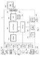
- FIG. 1 this schematically illustrates the overall system architecture of the Sony® Playstation 3® entertainment device.
- a system unit 10 is provided, with various peripheral devices connectable to the system unit.
- the system unit 10 comprises: a Cell processor 100; a Rambus® dynamic random access memory (XDRAM) unit 500; a Reality Synthesiser graphics unit 200 with a dedicated video random access memory (VRAM) unit 250; and an I/O bridge 700.
- XDRAM Rambus® dynamic random access memory
- VRAM dedicated video random access memory
- the system unit 10 also comprises a Blu Ray® Disk BD-ROM® optical disk reader 430 for reading from a disk 440 and a removable slot-in hard disk drive (HDD) 400, accessible through the I/O bridge 700.
- the system unit also comprises a memory card reader 450 for reading compact flash memory cards, Memory Stick® memory cards and the like, which is similarly accessible through the I/O bridge 700.
- the I/O bridge 700 also connects to four Universal Serial Bus (USB) 2.0 ports 710; a gigabit Ethernet port 720; an IEEE 802.11b/g wireless network (Wi-Fi) port 730; and a Bluetooth® wireless link port 740 capable of supporting up to seven Bluetooth connections.
- USB Universal Serial Bus
- Wi-Fi IEEE 802.11b/g wireless network
- Bluetooth® wireless link port 740 capable of supporting up to seven Bluetooth connections.
- the I/O bridge 700 handles all wireless, USB and Ethernet data, including data from one or more game controllers 751. For example when a user is playing a game, the I/O bridge 700 receives data from the game controller 751 via a Bluetooth link and directs it to the Cell processor 100, which updates the current state of the game accordingly.
- the wireless, USB and Ethernet ports also provide connectivity for other peripheral devices in addition to game controllers 751, such as: a remote control 752; a keyboard 753; a mouse 754; a portable entertainment device 755 such as a Sony Playstation Portable® entertainment device; a video camera such as an EyeToy® video camera 756; and a microphone headset 757.
- game controllers 751 such as: a remote control 752; a keyboard 753; a mouse 754; a portable entertainment device 755 such as a Sony Playstation Portable® entertainment device; a video camera such as an EyeToy® video camera 756; and a microphone headset 757.
- Such peripheral devices may therefore in principle be connected to the system unit 10 wirelessly; for example the portable entertainment device 755 may communicate via a Wi-Fi ad-hoc connection, whilst the microphone headset 757 may communicate via a Bluetooth link.
- Playstation 3 device is also potentially compatible with other peripheral devices such as digital video recorders (DVRs), set-top boxes, digital cameras, portable media players, Voice over IP telephones, mobile telephones, printers and scanners.
- DVRs digital video recorders
- set-top boxes digital cameras
- portable media players Portable media players
- Voice over IP telephones mobile telephones, printers and scanners.
- a legacy memory card reader 410 may be connected to the system unit via a USB port 710, enabling the reading of memory cards 420 of the kind used by the Playstation® or Playstation 2® devices.
- the game controller 751 is operable to communicate wirelessly with the system unit 10 via the Bluetooth link.
- the game controller 751 can instead be connected to a USB port, thereby also providing power by which to charge the battery of the game controller 751.
- the game controller is sensitive to motion in 6 degrees of freedom, corresponding to translation and rotation in each axis. Consequently gestures and movements by the user of the game controller may be translated as inputs to a game in addition to or instead of conventional button or joystick commands.
- other wirelessly enabled peripheral devices such as the Playstation Portable device or the Playstation Move (RTM) may be used as a controller.
- additional game or control information may be provided on the screen of the device.
- control information may be provided both by internal motion sensors and by video monitoring of the light on the Playstation Move device.
- Other alternative or supplementary control devices may also be used, such as a dance mat (not shown), a light gun (not shown), a steering wheel and pedals (not shown) or bespoke controllers, such as a single or several large buttons for a rapid-response quiz game (also not shown).
- the remote control 752 is also operable to communicate wirelessly with the system unit 10 via a Bluetooth link.
- the remote control 752 comprises controls suitable for the operation of the Blu Ray Disk BD-ROM reader 430 and for the navigation of disk content.
- the Blu Ray Disk BD-ROM reader 430 is operable to read CD-ROMs compatible with the Playstation and PlayStation 2 devices, in addition to conventional pre-recorded and recordable CDs, and so-called Super Audio CDs.
- the reader 430 is also operable to read DVD-ROMs compatible with the Playstation 2 and PlayStation 3 devices, in addition to conventional pre-recorded and recordable DVDs.
- the reader 430 is further operable to read BD-ROMs compatible with the Playstation 3 device, as well as conventional pre-recorded and recordable Blu-Ray Disks.
- the system unit 10 is operable to supply audio and video, either generated or decoded by the Playstation 3 device via the Reality Synthesiser graphics unit 200, through audio and video connectors to a display and sound output device 300 such as a monitor or television set having a display 305 and one or more loudspeakers 310.
- the audio connectors 210 may include conventional analogue and digital outputs whilst the video connectors 220 may variously include component video, S-video, composite video and a High Definition Multimedia Interface (HDMI) output. Consequently, video output may be in formats such as PAL or NTSC, or in 720p, 1080i or 1080p high definition.
- Audio processing (generation, decoding and so on) is performed by the Cell processor 100.
- the Playstation 3 device's operating system supports Dolby® 5.1 surround sound, Dolby® Theatre Surround (DTS), and the decoding of 7.1 surround sound from Blu-Ray® disks.
- DTS Dolby® Theatre Surround
- the video camera 756 comprises a single charge coupled device (CCD), an LED indicator, and hardware-based real-time data compression and encoding apparatus so that compressed video data may be transmitted in an appropriate format such as an intra-image based MPEG (motion picture expert group) standard for decoding by the system unit 10.
- the camera LED indicator is arranged to illuminate in response to appropriate control data from the system unit 10, for example to signify adverse lighting conditions.
- Embodiments of the video camera 756 may variously connect to the system unit 10 via a USB, Bluetooth or Wi-Fi communication port.
- Embodiments of the video camera may include one or more associated microphones and also be capable of transmitting audio data.
- the CCD may have a resolution suitable for high-definition video capture. In use, images captured by the video camera may for example be incorporated within a game or interpreted as game control inputs.
- a peripheral device such as a video camera or remote control via one of the communication ports of the system unit 10
- an appropriate piece of software such as a device driver should be provided.
- Device driver technology is well-known and will not be described in detail here, except to say that the skilled man will be aware that a device driver or similar software interface may be required in the present embodiment described.
- Software instructions implemented by the Cell processor 100 and/or the RSX 200 may be supplied at manufacture and stored on the HDD 400, and/or may be supplied on a data carrier or storage medium such as an optical disk or solid state memory, or via a transmission medium such as a wired or wireless network or internet connection, or via combinations of these.
- the software supplied at manufacture comprises system firmware and the Playstation 3 device's operating system (OS).
- the OS provides a user interface enabling a user to select from a variety of functions, including playing a game, listening to music, viewing photographs, or viewing a video.
- the interface takes the form of a so-called cross media-bar (XMB), with categories of function arranged horizontally.
- XMB cross media-bar
- the user navigates by moving through the function icons (representing the functions) horizontally using the game controller 751, remote control 752 or other suitable control device so as to highlight a desired function icon, at which point options pertaining to that function appear as a vertically scrollable list of option icons centred on that function icon, which may be navigated in analogous fashion.
- the Playstation 3 device may select appropriate options automatically (for example, by commencing the game), or may provide relevant options (for example, to select between playing an audio disk or compressing its content to the HDD 400).
- the OS provides an on-line capability, including a web browser, an interface with an on-line store from which additional game content, demonstration games (demos) and other media may be downloaded, and a friends management capability, providing on-line communication with other Playstation 3 device users nominated by the user of the current device; for example, by text, audio or video depending on the peripheral devices available.
- the on-line capability also provides for on-line communication, content download and content purchase during play of a suitably configured game, and for updating the firmware and OS of the Playstation 3 device itself. It will be appreciated that the term "on-line” does not imply the physical presence of wires, as the term can also apply to wireless connections of various types.
- the PS3 comprises one HDMI-out port. Consequently whilst it can support one 3D TV, it cannot easily support two separate conventional displays.
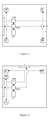
- an HDMI splitter box 1000 is connected to the PS3 (or any suitable source of videogame output) via an HDMI cable (not shown).
- the splitter box comprises an HDMI input 1010, two HDMI outputs 1020, 1030, a splitter logic 1040 (such as a CPU and conventional associated support architecture, or a custom chip), and optionally an audio splitter logic 1042, which may be separate from or part of the splitter logic 1040.
- the splitter box may comprise a transmitter 1050 for transmitting control signals to active shutter glasses.
- the transmitter may be optical (e.g. using infra-red signals) or use wireless radio (e.g. Bluetooth ®).
- the splitter box may contain its own extended display identification data (EDID), enabling the PS3 (or other suitable devices) to query the splitter box, for example to determine what modes and capabilities it has.
- EDID may be provided by a separate chip (not shown) generated by the splitter logic.
- the splitter box is operable in each of a plurality of modes having different capabilities. Modes may be selected by analysis of the signal received by the HDMI input, based upon existing HDMI protocols. Alternately or in addition, modes may be explicitly selected by the PS3 using predetermined signals via the HDMI cable, or where a Bluetooth communication system is provided in the splitter box, via Bluetooth. Alternatively or in addition, user inputs for mode selection may be provided on the box and/or via a user remote control.
- the modes affect how signals are sent to a primary display and, where used, a secondary display. Some modes are intended for use with one display (typically a 3D TV or projector), whilst others are intended for use with two displays (typically two conventional displays, such as conventional TVs, monitors or projectors).
- the splitter box provides in a standard 3D TV mode.
- the splitter box EDID identifies to the PS3 that it is able to receive a conventional 3D TV signal.
- the splitter logic reads the supported video modes from the display. The supported video modes are then reported by the splitter logic to the PS3. This enables the PS3 to output a 3D TV image in a mode compatible with the display.
- the splitter box then receives a conventional 3D TV signal at the HDMI input and, providing it corresponds to one of the reported supported video modes, it relays it to the display.
- a 3D TV may not support a dual-view mode in which two monoscopic (non-stereoscopic) images are tow be view by two respective users or groups of users.
- the splitter box supports a 3D TV dual view mode.
- the splitter box EDID identifies to the PS3 that it is able to receive a dual-view 3D TV signal.
- the splitter logic reads the supported video modes from the display. The supported video modes are then reported by the splitter logic to the PS3.
- the splitter box identifies itself to the conventional 3D TV as a conventional 3D TV signal source.
- the PS3 then transmits a dual view signal as a 3D signal in a conventional manner, and this is sent via the splitter box to the 3D TV, which displays it as if it is a conventional 3D image.
- the signal is nominally a 3D TV signal, but where the left and right stereoscopic images are conventionally encoded, the signal instead contains first and second player viewpoints.
- the conventional 3D TV is not capable of dual-view display. More specifically, a conventional 3D TV is arranged to send control signals to all paired active shutter glasses to alternate between left and right lenses in sync with alternate displayed images. However, this is the incorrect approach for a dual view signal, as it would result in both players seeing a confused jumble of images from both viewpoints.
- the splitter box (via Bluetooth, as a non-limiting example), sends a different set of control signals to the active shutter glasses, telling respective active shutter glasses to blink (i.e. make opaque) both lenses in sync with every other image, so as to only see a respective one of the dual views.
- the same pair of active shutter glasses can be used for both conventional 3D viewing and in dual view mode, depending upon whether they were paired under Bluetooth with the TV or with the splitter box.
- the splitter logic may signal to the PS3 to generate these Bluetooth control signals.
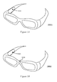
- active shutter glasses 3000A comprise a Bluetooth receiver 3010 operable to pair with either a TV or the splitter box (or the PS3, as applicable).
- a button to activate the pairing process may also be provided (not shown).
- the splitter box in combination with a conventional 3D TV can provide a dual-view capability on that 3D TV.
- a pair of active shutter glasses 3000B may comprise an infra-red receiver 3030 and be controlled by infra-red signals.
- the glasses could still receive infra-red control signals from the TV.
- the splitter box can nevertheless transmit infra-red signals of its own.
- a signal detector logic 3020 in the glasses is then arranged to distinguish both signal types (e.g. by correlation with stored templates) and where the splitter box's signal is detected in addition to the TV's, then the signal detector logic can be arranged to give preference to the control signals from the splitter box. In this way the glasses can switch from a default 3D mode controlled by the TV to a dual-view mode controlled by the splitter box when the splitter box is in this mode.
- the two displays may be a primary display and a secondary display.
- the primary display may be a main display that is permanently connected to the splitter box, whilst the secondary display is a visiting display temporarily connected to the splitter box (for example a smaller portable TV brought by a friend).
- the secondary display is a visiting display temporarily connected to the splitter box (for example a smaller portable TV brought by a friend).
- this is merely an example.
- which display is treated as the primary display may be based on a number of factors.
- the primary display may taken to be only one of two displays that is capable of displaying 3D TV signals.
- the primary display may be taken to be the one reporting the largest screen size and/or highest native resolution.
- the primary display may be defined as the display connected to a particular one of the HDMI outputs, which may consequently be marked as being for a primary display.
- a user-operable switch or remote control option may allow the user to specify which display is the primary display.
- the two displays may be of different sizes, and may also have different capabilities, such as different native resolutions.
- the splitter box supports a standard TV splitter mode.
- the splitter box EDID reports that the splitter box is a conventional HDMI receiver, and the splitter box takes a standard (monoscopic) HDMI signal received at the HDMI input.
- the splitter logic simply duplicates the signal for both HDMI outputs, thereby enabling identical display of the signal on two displays.
- the splitter logic reads the supported video modes from the primary display and reports these to the PS3 in a similar manner to that for the standard 3D TV mode discussed previously.
- splitter logic also reads the supported video modes of the secondary display, and compares these with the modes of the primary display. The splitter logic then only reports to the PS3 those modes found in common between the primary and secondary displays. This advantageously ensures that the PS3's output will be visible on both displays. This may be a factor when, for example, a smaller secondary TV is only capable of a 720p resolution, whilst the primary display is also capable of 1080p resolution.
- the splitter box supports a 3D TV splitter mode.
- the splitter box EDID identifies to the PS3 that it is able to receive a conventional 3D TV signal.
- the splitter box then operates in a similar manner to the standard splitter mode above, but using a 3D TV signal as an input. Consequently the 3D TV signal is duplicated and sent to the HDMI outputs.
- the splitter logic reads the supported video modes of both displays. If the splitter logic detects that only one of the displays is a 3D TV, whilst the other display is a conventional (monoscopic) TV, then the splitter logic splits the signal to provide the 3D TV with the 3D TV signal, and to provide the conventional display with only one of the stereoscopic pair of images.
- image processing means may be included in the splitter logic to extract and/or format the provided image in a manner supported by the conventional television. Such stereo to mono conversion techniques are discussed later herein.
- the splitter box supports a conventional TV dual-view splitter mode.
- the output from the PS3 is a dual view 3D TV signal.
- this signal is nominally a 3D TV signal, but where the left and right stereoscopic images are conventionally encoded, the signal instead contains first and second player viewpoints.
- the splitter box EDID identifies to the PS3 that it is able to receive a dual-view 3D TV signal. Consequently the PS3 operates as it if is connected to a dual-view capable 3D TV. Meanwhile, the splitter box identifies itself to each of two connected TVs as a conventional (monoscopic) HDMI source.
- the PS3 runs a dual-view capable application, such as a game.
- the PS3 then operates as though it is connected to a dual-view capable 3D TV, and outputs a dual-view 3D TV image for the viewpoints of first and second players of the game, as described previously.
- the splitter logic provides the conventional primary and secondary displays respectively with alternate frames of the 3D TV image corresponding to the alternate viewpoints, formatted as conventional (monoscopic) HDMI television signals.
- the splitter logic consistently extracts image frames corresponding to the viewpoint of the first player and supplies these to one of the primary and secondary displays as a conventional monoscopic image, and also consistently extracts image frames corresponding to the viewpoint of the second player and supplies these to the other of the primary and secondary displays as a conventional monoscopic image.
- the splitter logic may support one or more of the following stereo-to-mono extraction (conversion) modes:
- first and second dual-view images are vertically compressed and stacked in a progressive scan image
- the top and bottom halves of this image are separated and vertically expanded to form two conventional interlaced images, one for each display.
- a 1080p stereoscopic image signal input results in two 1080i mono image outputs.
- each extraction mode appropriate modifications to the header and/or data structure of the mono output images may be implemented. For example, metadata associated with the image may be changed to indicate that the resulting image frame is a conventional interlaced image frame in a format recognised by the intended display.
- left and right stereo images may be horizontally compressed and transmitted side by side in an image.
- left and right halves can be separated and horizontally expanded to form two images.
- the splitter box implements the separation of the 3D images that is normally implemented by a 3D TV, and additionally provides a suitable data wrapper to forward the two separated images as a conventional monoscopic images to a respective display.
- this process is transparent to the PS3. Consequently with the splitter box connected, the PS3 can generate dual-view 3D signals that are usable by a dual-view capable 3D TV, or a conventional 3D TV whose active shutter glasses can be paired to the splitter box, or to two conventional monoscopic TVs. As a result the number of people who are able to use the dual view capability of a game is increased, making provision of such a facility more attractive to game developers.
- This provides the opportunity to also generate respective audio separately for the different viewpoints of the players, such that audio for the position of a first player within the game environment is played by their display, whilst audio for the position of a second player within the game environment is played by the other display.
- This provides for a more immersive experience than if the common audio normally sent to a dual-view 3D TV is also sent to both conventional TVs.
- the PS3 is operable in a corresponding conventional TV dual-view splitter mode to format the audio signal that it outputs on the single HDMI channel to enable the audio splitter logic of the splitter box to generate separate audio for the two conventional displays.
- HDMI audio supports 5.1 or 7.1 channel surround sound a predetermined four of these channels can instead be supplied with two pairs of stereo audio signals corresponding to the audio appropriate to the position of each of the two players in the videogame.
- the audio splitter logic of the splitter box is then operable to extract these two stereo audio signals from the 5.1 or 7.1 audio signal received from the PS3, and respectively incorporates them into the HDMI signal being transmitted to the respective display.
- this mapping means that if a user routes (or also routes) their HDMI signal via a multimedia amplifier 2000, then the resulting deployment of the two stereo signals within a 5.1 or 7.1 speaker configuration would enable the secondary display to be mounted between the rear speakers of such a configuration and in that position enjoy apparently correct stereo reproduction.
- the stereo signal for the primary display could be sent on the left front and centre front channels
- the stereo signal for the secondary display could be sent with the left signal on the right front channel and the right signal on the right rear channel, so that the players and displays could be mounted at 90 degrees to each other.
- the PS3 is operable (either under instruction from the OS or the dual-view enabled game itself) to allow the users to specify the position of the secondary display in the case where audio will be sent to a 5.1 or 7.1 surround-sound system, so that the PS3 can select an appropriate set of channels to generate respective stereo sound on the system consistent with the position of the displays.
- the splitter box can drive either just the loudspeakers of the displays, or a separate 5.1 or 7.1 loudspeaker system, or both.
- the components of the splitter box as described herein may form part of a more general peripheral device for an entertainment device such as the PS3 (or vice versa).
- the components of the splitter box may form part of a digital video broadcast TV receiver such as the Sony ® PlayTV ® or PlayTV 2 peripheral, which receives DVB broadcasts and sends them to the PS3 for display or recording, and which is controlled by the PS3.
- the HDMI input 1010 may be replaced by or supplemented with a USB input/output port.
- the receiver may also act as a further video image source for conventional and 3D TV images to be split as described herein by the splitter logic.
- the received signal may be passed directly to the splitter logic, or the signal may be sent to the PS3 for processing and then received back from the Playstation 3 via the HDMI input 1010, optionally augmented by additional image data such as an electronic program guide.
- the Playstation 3 will remain the source of dual-view videogame images for splitting or display as described herein.
- the splitter box operates as an image transfer apparatus in conventional TV Dual View mode, and comprises an input (e.g. the HDMI input 1010) operable to receive a signal comprising two non-stereoscopic images for different respective viewpoints of a virtual environment (i.e. a dual-view videogame signal from the PS3).
- the splitter box comprises the first output and a second output (HDMI outputs 1020 and 1030) and the signal splitter logic 1040.
- the signal splitter logic is then able to extract and separate the two non-stereoscopic images from the received signal in the manner described previously herein.
- the signal splitter logic can then format each of the two separated images for reception by a respective conventional 2D display. As noted previously, this may involve use of suitable EDID signals to the displays and also any known modification of header data or data formatting required to be compatible with expected conventional 2D TV signals. Then the splitter box is operable to output to the first output and the second output a respective signal comprising one of the two separate images.
- the splitter box is arranged to transmit extended display identification data to a source of the received signal, the data indicating that the apparatus is capable of dual-view display of the two images, and in which the apparatus is arranged to transmit extended display identification data to a recipient of the transmitted signal, the data indicating that the apparatus is a source of conventional 2D TV signals.
- the two non-stereoscopic images may be combined within a dual view signal in a number of different ways. Consequently the splitter box may be operable to extract the images in one or more of the following non-limiting ways:
- the signal splitter logic is operable to extract and separate the two images from a received signal in which the two images are vertically compressed and stacked in a progressive scan image, by separating the top and bottom halves of this progressive scan image and vertically expanding these to form two conventional interlaced 2D images.
- the signal splitter logic is operable to extract and separate the two images from a received signal in which the two images are presented as alternating separate image frames over time by extracting alternate frames to form two series of conventional 2D images.
- the splitter box may comprise an audio splitter logic 1042 (which as noted previously may be part of the main signal splitter logic 1040).
- This audio splitter logic is operable to extract and separate the two stereo audio signals from a surround-sound signal forming part of the received signal comprising the two non-stereoscopic images. Once separated out, it can then output to the first output and the second output a respective signal comprising a respective one of the two separated stereo audio signals.
- the splitter box may also operate in any of the modes described herein, including for example the 3D TV dual view mode and the 3D TV splitter mode.
- the splitter box operates as an image transfer apparatus in which the input 1010 is operable to receive a signal comprising a true stereoscopic pair of images for display on a 3D display.
- the signal splitter is operable to duplicate the signal for routing to the two outputs.
- the splitter box is then arranged to output the signal to a display detected as a 3D display.
- the signal splitter logic is also operable to detect a whether a display connected to each output is a 3D display, and to convert the signal to a monoscopic signal for output to a display detected as being a conventional 2D display.
- the splitter box operates as an image transfer apparatus, which comprises a transmitter 1050 operable to transmit control signals to at least two active shutter glasses, the control signals arranged to allow respective wearers of the glasses to only view a respective one of the two non-stereoscopic images, and in which the first output is operable to transmit a signal comprising the two non-stereoscopic images formatted as a stereoscopic image to at least a first display.
- the formatting will be implemented by the signal splitting logic. As noted previously, this may be achieved by use of EDID signals to the display and also any known modification of header data or data formatting required to be compatible with expected 3D TV signals.
- the splitter box will typically form part of an audio visual system comprising the splitter box itself and an entertainment device 10 such as the PS3, operable to generate the signal comprising two images for different respective non-stereoscopic viewpoints of a virtual environment and also operable to transmit this signal to the splitter box, for example via an HDMI lead to the splitter box HDMI input 1010.
- the splitter box may take the form of a separate plug-in peripheral device for a console such as the PS3, or may be integrated within such a console. Similarly it may be integrated into a display device (such as a 3D TV), such that one output links internally to the integrated TV and one output links to an external port of the TV, enabling the second TV to be connected to it.
- a display device such as a 3D TV
- the components of the splitter box may similarly be incorporated within a digital video broadcast receiver (or vice-versa), in which the receiver is operable to send the received digital video broadcast signals to the PS3 (e.g. via a USB cable), and the HDMI input 1010 is arranged to receive a signal comprising images from the digital video broadcast back from the PS3, which may be augmented with additional graphical overlays such as electronic program guide data.
- the receiver is operable to send the received digital video broadcast signals to the PS3 (e.g. via a USB cable)
- the HDMI input 1010 is arranged to receive a signal comprising images from the digital video broadcast back from the PS3, which may be augmented with additional graphical overlays such as electronic program guide data.
- the entertainment device may be operable to configure a surround-sound signal (such as 5.1 or 7.1 surround sound) for inclusion with the signal transmitted to the image transfer apparatus, the surround-sound signal comprising two separate stereo audio signals (i.e. two sets of two channels arranged on a subset of the six or eight surround sound channels).
- a first stereo audio signal has a left channel on the surround sound front left channel, and a right channel on the surround sound front right channel
- a second stereo audio signal has a left channel on the surround sound rear right channel, and a right channel on the surround sound rear left channel.
- the entertainment device can comprise a user interface for setting which surround sound-channels are used to carry the two stereo audio signals.
- a method of image transfer comprises:
- the required adaptation to existing parts of a conventional equivalent device may be implemented in the form of a computer program product or similar object of manufacture comprising processor implementable instructions stored on a data carrier such as a floppy disk, optical disk, hard disk, PROM, RAM, flash memory or any combination of these or other storage media, or transmitted via data signals on a network such as an Ethernet, a wireless network, the Internet, or any combination of these of other networks, or realised in hardware as an ASIC (application specific integrated circuit) or an FPGA (field programmable gate array) or other configurable circuit suitable to use in adapting the conventional equivalent device.
- a data carrier such as a floppy disk, optical disk, hard disk, PROM, RAM, flash memory or any combination of these or other storage media
- a network such as an Ethernet, a wireless network, the Internet, or any combination of these of other networks, or realised in hardware as an ASIC (application specific integrated circuit) or an FPGA (field programmable gate array) or other configurable circuit suitable to use in adapting the conventional equivalent device.
Landscapes
- Engineering & Computer Science (AREA)
- Multimedia (AREA)
- Signal Processing (AREA)
- Testing, Inspecting, Measuring Of Stereoscopic Televisions And Televisions (AREA)
Applications Claiming Priority (1)
| Application Number | Priority Date | Filing Date | Title |
|---|---|---|---|
| GB1117927.2A GB2495907B (en) | 2011-10-18 | 2011-10-18 | Image transfer apparatus and method |
Publications (3)
| Publication Number | Publication Date |
|---|---|
| EP2584786A2 true EP2584786A2 (de) | 2013-04-24 |
| EP2584786A3 EP2584786A3 (de) | 2015-05-13 |
| EP2584786B1 EP2584786B1 (de) | 2018-12-26 |
Family
ID=45219852
Family Applications (1)
| Application Number | Title | Priority Date | Filing Date |
|---|---|---|---|
| EP12161112.3A Active EP2584786B1 (de) | 2011-10-18 | 2012-03-23 | Bildübertragungsvorrichtung und -verfahren |
Country Status (3)
| Country | Link |
|---|---|
| US (1) | US9445070B2 (de) |
| EP (1) | EP2584786B1 (de) |
| GB (1) | GB2495907B (de) |
Families Citing this family (1)
| Publication number | Priority date | Publication date | Assignee | Title |
|---|---|---|---|---|
| US11025892B1 (en) | 2018-04-04 | 2021-06-01 | James Andrew Aman | System and method for simultaneously providing public and private images |
Family Cites Families (16)
| Publication number | Priority date | Publication date | Assignee | Title |
|---|---|---|---|---|
| US4814869A (en) * | 1987-04-27 | 1989-03-21 | Oliver Jr Robert C | Video surveillance system |
| US6765568B2 (en) * | 2000-06-12 | 2004-07-20 | Vrex, Inc. | Electronic stereoscopic media delivery system |
| GB2372164B (en) * | 2000-12-23 | 2005-01-19 | Michael Edward Ries | Video signal separator |
| US7804995B2 (en) * | 2002-07-02 | 2010-09-28 | Reald Inc. | Stereoscopic format converter |
| US7098868B2 (en) * | 2003-04-08 | 2006-08-29 | Microsoft Corporation | Display source divider |
| WO2005070097A2 (en) * | 2004-01-09 | 2005-08-04 | Masonware Partners, Llc | Passive surround sound adapter |
| US20070153122A1 (en) * | 2005-12-30 | 2007-07-05 | Ayite Nii A | Apparatus and method for simultaneous multiple video channel viewing |
| US20100083341A1 (en) * | 2008-09-30 | 2010-04-01 | Hector Gonzalez | Multiple Signal Output System and Technology (MSOST) |
| US9684482B2 (en) * | 2009-01-13 | 2017-06-20 | Synaptics Incorporated | Multi-monitor display system |
| WO2010144478A2 (en) * | 2009-06-08 | 2010-12-16 | Reald Inc. | Shutter-glass eyewear control |
| US8666081B2 (en) * | 2009-08-07 | 2014-03-04 | Lg Electronics, Inc. | Apparatus for processing a media signal and method thereof |
| KR101626742B1 (ko) * | 2009-12-31 | 2016-06-03 | 엘지디스플레이 주식회사 | 멀티 영상 표시 시스템 |
| WO2011084169A1 (en) * | 2010-01-07 | 2011-07-14 | Thomson Licensing | Method and apparatus for providing for the display of video content |
| KR101445777B1 (ko) * | 2010-02-19 | 2014-11-04 | 삼성전자 주식회사 | 재생 기기 및 그 제어방법 |
| KR20110115806A (ko) | 2010-04-16 | 2011-10-24 | 삼성전자주식회사 | 디스플레이 장치 및 3d 안경, 그리고 이를 포함하는 디스플레이 시스템 |
| KR20110128099A (ko) | 2010-05-20 | 2011-11-28 | 삼성전자주식회사 | 입체 영상 표시 장치 및 그 구동 방법 |
-
2011
- 2011-10-18 GB GB1117927.2A patent/GB2495907B/en active Active
-
2012
- 2012-03-23 EP EP12161112.3A patent/EP2584786B1/de active Active
- 2012-10-12 US US13/650,416 patent/US9445070B2/en active Active
Non-Patent Citations (1)
| Title |
|---|
| None |
Also Published As
| Publication number | Publication date |
|---|---|
| EP2584786A3 (de) | 2015-05-13 |
| EP2584786B1 (de) | 2018-12-26 |
| US20130093846A1 (en) | 2013-04-18 |
| GB2495907B (en) | 2013-09-18 |
| US9445070B2 (en) | 2016-09-13 |
| GB201117927D0 (en) | 2011-11-30 |
| GB2495907A (en) | 2013-05-01 |
Similar Documents
| Publication | Publication Date | Title |
|---|---|---|
| KR101719583B1 (ko) | 멀티뷰 디스플레이 시스템 | |
| US8269822B2 (en) | Display viewing system and methods for optimizing display view based on active tracking | |
| TWI459369B (zh) | 使用頭戴式顯示器用於共享觀察經驗之裝置系統及方法 | |
| JP2010258583A (ja) | 立体画像表示装置、立体画像再生装置および立体画像視認システム | |
| US20110254837A1 (en) | Image display apparatus and method for controlling the same | |
| US8764565B2 (en) | Apparatus and method of audio reproduction | |
| JP4996720B2 (ja) | 画像処理装置、画像処理プログラム、及び画像処理方法 | |
| US9516292B2 (en) | Image transfer apparatus and method | |
| JP5066244B2 (ja) | 映像再生装置及び映像再生方法 | |
| US20110134226A1 (en) | 3d image display apparatus and method for determining 3d image thereof | |
| EP2584786B1 (de) | Bildübertragungsvorrichtung und -verfahren | |
| JP2019213196A (ja) | 三次元360°映像データの伝送方法とそのためのディスプレイ装置及び映像保存装置 | |
| KR20110083914A (ko) | 3d 썸네일을 표시하는 영상표시장치 및 그 동작 제어방법 | |
| JP2012160984A (ja) | 立体音響再生装置および立体音響再生方法 | |
| KR101668245B1 (ko) | 원격제어장치로 제어할 수 있는 영상표시장치 및 그 동작 제어방법 | |
| JP2019057845A (ja) | 選択再生システム | |
| KR20120023218A (ko) | 2d 및 3d 겸용 디스플레이 장치, 3d 보조 장치 및 선택적인 디스플레이 방법 | |
| KR20110088952A (ko) | 썸네일 영상을 포함하는 3d 오브젝트를 표시할 수 있는 영상표시장치 및 그 동작 제어방법 | |
| KR20110086414A (ko) | 썸네일 영상을 포함하는 3d 오브젝트를 표시할 수 있는 영상표시장치 및 그 동작 제어방법 | |
| JP2012156950A (ja) | 映像再生装置 | |
| CN102378022A (zh) | 影像显示系统及再现装置 | |
| KR20140082535A (ko) | 다초점 영상을 생성하고 재현하기 위한 시스템 및 방법 |
Legal Events
| Date | Code | Title | Description |
|---|---|---|---|
| PUAI | Public reference made under article 153(3) epc to a published international application that has entered the european phase |
Free format text: ORIGINAL CODE: 0009012 |
|
| 17P | Request for examination filed |
Effective date: 20120329 |
|
| AK | Designated contracting states |
Kind code of ref document: A2 Designated state(s): AL AT BE BG CH CY CZ DE DK EE ES FI FR GB GR HR HU IE IS IT LI LT LU LV MC MK MT NL NO PL PT RO RS SE SI SK SM TR |
|
| AX | Request for extension of the european patent |
Extension state: BA ME |
|
| PUAL | Search report despatched |
Free format text: ORIGINAL CODE: 0009013 |
|
| AK | Designated contracting states |
Kind code of ref document: A3 Designated state(s): AL AT BE BG CH CY CZ DE DK EE ES FI FR GB GR HR HU IE IS IT LI LT LU LV MC MK MT NL NO PL PT RO RS SE SI SK SM TR |
|
| AX | Request for extension of the european patent |
Extension state: BA ME |
|
| RIC1 | Information provided on ipc code assigned before grant |
Ipc: H04N 13/04 20060101ALI20150409BHEP Ipc: H04N 13/00 20060101AFI20150409BHEP |
|
| RAP1 | Party data changed (applicant data changed or rights of an application transferred) |
Owner name: SONY INTERACTIVE ENTERTAINMENT EUROPE LIMITED |
|
| REG | Reference to a national code |
Ref country code: DE Ref legal event code: R079 Ref document number: 602012055033 Country of ref document: DE Free format text: PREVIOUS MAIN CLASS: H04N0013000000 Ipc: H04N0013300000 |
|
| RIC1 | Information provided on ipc code assigned before grant |
Ipc: H04N 13/30 20180101AFI20180601BHEP Ipc: H04N 13/106 20180101ALI20180601BHEP Ipc: H04N 13/167 20180101ALI20180601BHEP Ipc: H04N 13/139 20180101ALI20180601BHEP Ipc: H04N 13/341 20180101ALI20180601BHEP Ipc: H04N 13/189 20180101ALI20180601BHEP Ipc: A63F 13/843 20140101ALI20180601BHEP |
|
| GRAP | Despatch of communication of intention to grant a patent |
Free format text: ORIGINAL CODE: EPIDOSNIGR1 |
|
| STAA | Information on the status of an ep patent application or granted ep patent |
Free format text: STATUS: GRANT OF PATENT IS INTENDED |
|
| INTG | Intention to grant announced |
Effective date: 20180713 |
|
| GRAS | Grant fee paid |
Free format text: ORIGINAL CODE: EPIDOSNIGR3 |
|
| GRAA | (expected) grant |
Free format text: ORIGINAL CODE: 0009210 |
|
| STAA | Information on the status of an ep patent application or granted ep patent |
Free format text: STATUS: THE PATENT HAS BEEN GRANTED |
|
| AK | Designated contracting states |
Kind code of ref document: B1 Designated state(s): AL AT BE BG CH CY CZ DE DK EE ES FI FR GB GR HR HU IE IS IT LI LT LU LV MC MK MT NL NO PL PT RO RS SE SI SK SM TR |
|
| REG | Reference to a national code |
Ref country code: GB Ref legal event code: FG4D |
|
| REG | Reference to a national code |
Ref country code: CH Ref legal event code: EP |
|
| REG | Reference to a national code |
Ref country code: AT Ref legal event code: REF Ref document number: 1083040 Country of ref document: AT Kind code of ref document: T Effective date: 20190115 |
|
| REG | Reference to a national code |
Ref country code: DE Ref legal event code: R096 Ref document number: 602012055033 Country of ref document: DE |
|
| REG | Reference to a national code |
Ref country code: IE Ref legal event code: FG4D |
|
| REG | Reference to a national code |
Ref country code: NL Ref legal event code: FP |
|
| PG25 | Lapsed in a contracting state [announced via postgrant information from national office to epo] |
Ref country code: BG Free format text: LAPSE BECAUSE OF FAILURE TO SUBMIT A TRANSLATION OF THE DESCRIPTION OR TO PAY THE FEE WITHIN THE PRESCRIBED TIME-LIMIT Effective date: 20190326 Ref country code: HR Free format text: LAPSE BECAUSE OF FAILURE TO SUBMIT A TRANSLATION OF THE DESCRIPTION OR TO PAY THE FEE WITHIN THE PRESCRIBED TIME-LIMIT Effective date: 20181226 Ref country code: LT Free format text: LAPSE BECAUSE OF FAILURE TO SUBMIT A TRANSLATION OF THE DESCRIPTION OR TO PAY THE FEE WITHIN THE PRESCRIBED TIME-LIMIT Effective date: 20181226 Ref country code: LV Free format text: LAPSE BECAUSE OF FAILURE TO SUBMIT A TRANSLATION OF THE DESCRIPTION OR TO PAY THE FEE WITHIN THE PRESCRIBED TIME-LIMIT Effective date: 20181226 Ref country code: NO Free format text: LAPSE BECAUSE OF FAILURE TO SUBMIT A TRANSLATION OF THE DESCRIPTION OR TO PAY THE FEE WITHIN THE PRESCRIBED TIME-LIMIT Effective date: 20190326 Ref country code: FI Free format text: LAPSE BECAUSE OF FAILURE TO SUBMIT A TRANSLATION OF THE DESCRIPTION OR TO PAY THE FEE WITHIN THE PRESCRIBED TIME-LIMIT Effective date: 20181226 |
|
| REG | Reference to a national code |
Ref country code: LT Ref legal event code: MG4D |
|
| PG25 | Lapsed in a contracting state [announced via postgrant information from national office to epo] |
Ref country code: AL Free format text: LAPSE BECAUSE OF FAILURE TO SUBMIT A TRANSLATION OF THE DESCRIPTION OR TO PAY THE FEE WITHIN THE PRESCRIBED TIME-LIMIT Effective date: 20181226 Ref country code: SE Free format text: LAPSE BECAUSE OF FAILURE TO SUBMIT A TRANSLATION OF THE DESCRIPTION OR TO PAY THE FEE WITHIN THE PRESCRIBED TIME-LIMIT Effective date: 20181226 Ref country code: RS Free format text: LAPSE BECAUSE OF FAILURE TO SUBMIT A TRANSLATION OF THE DESCRIPTION OR TO PAY THE FEE WITHIN THE PRESCRIBED TIME-LIMIT Effective date: 20181226 Ref country code: GR Free format text: LAPSE BECAUSE OF FAILURE TO SUBMIT A TRANSLATION OF THE DESCRIPTION OR TO PAY THE FEE WITHIN THE PRESCRIBED TIME-LIMIT Effective date: 20190327 |
|
| REG | Reference to a national code |
Ref country code: AT Ref legal event code: MK05 Ref document number: 1083040 Country of ref document: AT Kind code of ref document: T Effective date: 20181226 |
|
| PG25 | Lapsed in a contracting state [announced via postgrant information from national office to epo] |
Ref country code: CZ Free format text: LAPSE BECAUSE OF FAILURE TO SUBMIT A TRANSLATION OF THE DESCRIPTION OR TO PAY THE FEE WITHIN THE PRESCRIBED TIME-LIMIT Effective date: 20181226 Ref country code: PT Free format text: LAPSE BECAUSE OF FAILURE TO SUBMIT A TRANSLATION OF THE DESCRIPTION OR TO PAY THE FEE WITHIN THE PRESCRIBED TIME-LIMIT Effective date: 20190426 Ref country code: IT Free format text: LAPSE BECAUSE OF FAILURE TO SUBMIT A TRANSLATION OF THE DESCRIPTION OR TO PAY THE FEE WITHIN THE PRESCRIBED TIME-LIMIT Effective date: 20181226 Ref country code: PL Free format text: LAPSE BECAUSE OF FAILURE TO SUBMIT A TRANSLATION OF THE DESCRIPTION OR TO PAY THE FEE WITHIN THE PRESCRIBED TIME-LIMIT Effective date: 20181226 Ref country code: ES Free format text: LAPSE BECAUSE OF FAILURE TO SUBMIT A TRANSLATION OF THE DESCRIPTION OR TO PAY THE FEE WITHIN THE PRESCRIBED TIME-LIMIT Effective date: 20181226 |
|
| PG25 | Lapsed in a contracting state [announced via postgrant information from national office to epo] |
Ref country code: EE Free format text: LAPSE BECAUSE OF FAILURE TO SUBMIT A TRANSLATION OF THE DESCRIPTION OR TO PAY THE FEE WITHIN THE PRESCRIBED TIME-LIMIT Effective date: 20181226 Ref country code: IS Free format text: LAPSE BECAUSE OF FAILURE TO SUBMIT A TRANSLATION OF THE DESCRIPTION OR TO PAY THE FEE WITHIN THE PRESCRIBED TIME-LIMIT Effective date: 20190426 Ref country code: SK Free format text: LAPSE BECAUSE OF FAILURE TO SUBMIT A TRANSLATION OF THE DESCRIPTION OR TO PAY THE FEE WITHIN THE PRESCRIBED TIME-LIMIT Effective date: 20181226 Ref country code: RO Free format text: LAPSE BECAUSE OF FAILURE TO SUBMIT A TRANSLATION OF THE DESCRIPTION OR TO PAY THE FEE WITHIN THE PRESCRIBED TIME-LIMIT Effective date: 20181226 Ref country code: SM Free format text: LAPSE BECAUSE OF FAILURE TO SUBMIT A TRANSLATION OF THE DESCRIPTION OR TO PAY THE FEE WITHIN THE PRESCRIBED TIME-LIMIT Effective date: 20181226 |
|
| REG | Reference to a national code |
Ref country code: DE Ref legal event code: R097 Ref document number: 602012055033 Country of ref document: DE |
|
| PG25 | Lapsed in a contracting state [announced via postgrant information from national office to epo] |
Ref country code: AT Free format text: LAPSE BECAUSE OF FAILURE TO SUBMIT A TRANSLATION OF THE DESCRIPTION OR TO PAY THE FEE WITHIN THE PRESCRIBED TIME-LIMIT Effective date: 20181226 Ref country code: MC Free format text: LAPSE BECAUSE OF FAILURE TO SUBMIT A TRANSLATION OF THE DESCRIPTION OR TO PAY THE FEE WITHIN THE PRESCRIBED TIME-LIMIT Effective date: 20181226 Ref country code: DK Free format text: LAPSE BECAUSE OF FAILURE TO SUBMIT A TRANSLATION OF THE DESCRIPTION OR TO PAY THE FEE WITHIN THE PRESCRIBED TIME-LIMIT Effective date: 20181226 |
|
| REG | Reference to a national code |
Ref country code: CH Ref legal event code: PL |
|
| PLBE | No opposition filed within time limit |
Free format text: ORIGINAL CODE: 0009261 |
|
| STAA | Information on the status of an ep patent application or granted ep patent |
Free format text: STATUS: NO OPPOSITION FILED WITHIN TIME LIMIT |
|
| PG25 | Lapsed in a contracting state [announced via postgrant information from national office to epo] |
Ref country code: LU Free format text: LAPSE BECAUSE OF NON-PAYMENT OF DUE FEES Effective date: 20190323 |
|
| 26N | No opposition filed |
Effective date: 20190927 |
|
| REG | Reference to a national code |
Ref country code: BE Ref legal event code: MM Effective date: 20190331 |
|
| PG25 | Lapsed in a contracting state [announced via postgrant information from national office to epo] |
Ref country code: LI Free format text: LAPSE BECAUSE OF NON-PAYMENT OF DUE FEES Effective date: 20190331 Ref country code: CH Free format text: LAPSE BECAUSE OF NON-PAYMENT OF DUE FEES Effective date: 20190331 Ref country code: IE Free format text: LAPSE BECAUSE OF NON-PAYMENT OF DUE FEES Effective date: 20190323 |
|
| PG25 | Lapsed in a contracting state [announced via postgrant information from national office to epo] |
Ref country code: SI Free format text: LAPSE BECAUSE OF FAILURE TO SUBMIT A TRANSLATION OF THE DESCRIPTION OR TO PAY THE FEE WITHIN THE PRESCRIBED TIME-LIMIT Effective date: 20181226 Ref country code: BE Free format text: LAPSE BECAUSE OF NON-PAYMENT OF DUE FEES Effective date: 20190331 |
|
| PG25 | Lapsed in a contracting state [announced via postgrant information from national office to epo] |
Ref country code: TR Free format text: LAPSE BECAUSE OF FAILURE TO SUBMIT A TRANSLATION OF THE DESCRIPTION OR TO PAY THE FEE WITHIN THE PRESCRIBED TIME-LIMIT Effective date: 20181226 |
|
| REG | Reference to a national code |
Ref country code: DE Ref legal event code: R081 Ref document number: 602012055033 Country of ref document: DE Owner name: SONY INTERACTIVE ENTERTAINMENT INC., JP Free format text: FORMER OWNER: SONY INTERACTIVE ENTERTAINMENT EUROPE LIMITED, LONDON, GB |
|
| PG25 | Lapsed in a contracting state [announced via postgrant information from national office to epo] |
Ref country code: MT Free format text: LAPSE BECAUSE OF NON-PAYMENT OF DUE FEES Effective date: 20190323 |
|
| REG | Reference to a national code |
Ref country code: GB Ref legal event code: 732E Free format text: REGISTERED BETWEEN 20200723 AND 20200729 |
|
| PG25 | Lapsed in a contracting state [announced via postgrant information from national office to epo] |
Ref country code: CY Free format text: LAPSE BECAUSE OF FAILURE TO SUBMIT A TRANSLATION OF THE DESCRIPTION OR TO PAY THE FEE WITHIN THE PRESCRIBED TIME-LIMIT Effective date: 20181226 |
|
| PG25 | Lapsed in a contracting state [announced via postgrant information from national office to epo] |
Ref country code: HU Free format text: LAPSE BECAUSE OF FAILURE TO SUBMIT A TRANSLATION OF THE DESCRIPTION OR TO PAY THE FEE WITHIN THE PRESCRIBED TIME-LIMIT; INVALID AB INITIO Effective date: 20120323 |
|
| PG25 | Lapsed in a contracting state [announced via postgrant information from national office to epo] |
Ref country code: MK Free format text: LAPSE BECAUSE OF FAILURE TO SUBMIT A TRANSLATION OF THE DESCRIPTION OR TO PAY THE FEE WITHIN THE PRESCRIBED TIME-LIMIT Effective date: 20181226 |
|
| P01 | Opt-out of the competence of the unified patent court (upc) registered |
Effective date: 20230519 |
|
| PGFP | Annual fee paid to national office [announced via postgrant information from national office to epo] |
Ref country code: NL Payment date: 20260219 Year of fee payment: 15 |
|
| PGFP | Annual fee paid to national office [announced via postgrant information from national office to epo] |
Ref country code: GB Payment date: 20260220 Year of fee payment: 15 |
|
| PGFP | Annual fee paid to national office [announced via postgrant information from national office to epo] |
Ref country code: DE Payment date: 20260219 Year of fee payment: 15 |
|
| PGFP | Annual fee paid to national office [announced via postgrant information from national office to epo] |
Ref country code: FR Payment date: 20260219 Year of fee payment: 15 |