EP2584200B1 - Gas injection valve for a compressor, compressor with such a gas injection valve and method for operating a compressor with such a gas injection valve - Google Patents
Gas injection valve for a compressor, compressor with such a gas injection valve and method for operating a compressor with such a gas injection valve Download PDFInfo
- Publication number
- EP2584200B1 EP2584200B1 EP12189089.1A EP12189089A EP2584200B1 EP 2584200 B1 EP2584200 B1 EP 2584200B1 EP 12189089 A EP12189089 A EP 12189089A EP 2584200 B1 EP2584200 B1 EP 2584200B1
- Authority
- EP
- European Patent Office
- Prior art keywords
- valve
- piston
- gas inlet
- compressor
- section
- Prior art date
- Legal status (The legal status is an assumption and is not a legal conclusion. Google has not performed a legal analysis and makes no representation as to the accuracy of the status listed.)
- Active
Links
- 238000000034 method Methods 0.000 title claims description 14
- 238000002347 injection Methods 0.000 title description 7
- 239000007924 injection Substances 0.000 title description 7
- 239000012530 fluid Substances 0.000 claims description 36
- 230000008878 coupling Effects 0.000 claims description 8
- 238000010168 coupling process Methods 0.000 claims description 8
- 238000005859 coupling reaction Methods 0.000 claims description 8
- 239000003921 oil Substances 0.000 description 43
- 238000007789 sealing Methods 0.000 description 22
- 238000007906 compression Methods 0.000 description 16
- 239000003570 air Substances 0.000 description 14
- 230000006835 compression Effects 0.000 description 12
- 230000036316 preload Effects 0.000 description 6
- 230000001276 controlling effect Effects 0.000 description 4
- 238000011161 development Methods 0.000 description 3
- 230000018109 developmental process Effects 0.000 description 3
- 238000005553 drilling Methods 0.000 description 3
- 230000033001 locomotion Effects 0.000 description 3
- 239000000203 mixture Substances 0.000 description 3
- 238000000926 separation method Methods 0.000 description 3
- XLYOFNOQVPJJNP-UHFFFAOYSA-N water Substances O XLYOFNOQVPJJNP-UHFFFAOYSA-N 0.000 description 3
- 230000007423 decrease Effects 0.000 description 2
- 230000007547 defect Effects 0.000 description 2
- 210000003746 feather Anatomy 0.000 description 2
- 238000009434 installation Methods 0.000 description 2
- 238000004519 manufacturing process Methods 0.000 description 2
- 230000007246 mechanism Effects 0.000 description 2
- 230000008569 process Effects 0.000 description 2
- 238000013022 venting Methods 0.000 description 2
- 208000027418 Wounds and injury Diseases 0.000 description 1
- 230000009471 action Effects 0.000 description 1
- 239000012080 ambient air Substances 0.000 description 1
- 230000033228 biological regulation Effects 0.000 description 1
- 230000005540 biological transmission Effects 0.000 description 1
- 238000002485 combustion reaction Methods 0.000 description 1
- 230000000295 complement effect Effects 0.000 description 1
- 230000006378 damage Effects 0.000 description 1
- 230000000694 effects Effects 0.000 description 1
- 238000005265 energy consumption Methods 0.000 description 1
- 230000005484 gravity Effects 0.000 description 1
- 208000014674 injury Diseases 0.000 description 1
- 230000001050 lubricating effect Effects 0.000 description 1
- 239000010687 lubricating oil Substances 0.000 description 1
- 230000000149 penetrating effect Effects 0.000 description 1
- 238000007639 printing Methods 0.000 description 1
- 238000005086 pumping Methods 0.000 description 1
- 230000009467 reduction Effects 0.000 description 1
- 230000001105 regulatory effect Effects 0.000 description 1
- 230000003584 silencer Effects 0.000 description 1
- 238000011144 upstream manufacturing Methods 0.000 description 1
Images


Classifications
-
- F—MECHANICAL ENGINEERING; LIGHTING; HEATING; WEAPONS; BLASTING
- F04—POSITIVE - DISPLACEMENT MACHINES FOR LIQUIDS; PUMPS FOR LIQUIDS OR ELASTIC FLUIDS
- F04C—ROTARY-PISTON, OR OSCILLATING-PISTON, POSITIVE-DISPLACEMENT MACHINES FOR LIQUIDS; ROTARY-PISTON, OR OSCILLATING-PISTON, POSITIVE-DISPLACEMENT PUMPS
- F04C29/00—Component parts, details or accessories of pumps or pumping installations, not provided for in groups F04C18/00 - F04C28/00
- F04C29/12—Arrangements for admission or discharge of the working fluid, e.g. constructional features of the inlet or outlet
- F04C29/124—Arrangements for admission or discharge of the working fluid, e.g. constructional features of the inlet or outlet with inlet and outlet valves specially adapted for rotary or oscillating piston pumps
- F04C29/126—Arrangements for admission or discharge of the working fluid, e.g. constructional features of the inlet or outlet with inlet and outlet valves specially adapted for rotary or oscillating piston pumps of the non-return type
-
- F—MECHANICAL ENGINEERING; LIGHTING; HEATING; WEAPONS; BLASTING
- F04—POSITIVE - DISPLACEMENT MACHINES FOR LIQUIDS; PUMPS FOR LIQUIDS OR ELASTIC FLUIDS
- F04C—ROTARY-PISTON, OR OSCILLATING-PISTON, POSITIVE-DISPLACEMENT MACHINES FOR LIQUIDS; ROTARY-PISTON, OR OSCILLATING-PISTON, POSITIVE-DISPLACEMENT PUMPS
- F04C28/00—Control of, monitoring of, or safety arrangements for, pumps or pumping installations specially adapted for elastic fluids
- F04C28/06—Control of, monitoring of, or safety arrangements for, pumps or pumping installations specially adapted for elastic fluids specially adapted for stopping, starting, idling or no-load operation
-
- F—MECHANICAL ENGINEERING; LIGHTING; HEATING; WEAPONS; BLASTING
- F04—POSITIVE - DISPLACEMENT MACHINES FOR LIQUIDS; PUMPS FOR LIQUIDS OR ELASTIC FLUIDS
- F04C—ROTARY-PISTON, OR OSCILLATING-PISTON, POSITIVE-DISPLACEMENT MACHINES FOR LIQUIDS; ROTARY-PISTON, OR OSCILLATING-PISTON, POSITIVE-DISPLACEMENT PUMPS
- F04C28/00—Control of, monitoring of, or safety arrangements for, pumps or pumping installations specially adapted for elastic fluids
- F04C28/24—Control of, monitoring of, or safety arrangements for, pumps or pumping installations specially adapted for elastic fluids characterised by using valves controlling pressure or flow rate, e.g. discharge valves or unloading valves
- F04C28/26—Control of, monitoring of, or safety arrangements for, pumps or pumping installations specially adapted for elastic fluids characterised by using valves controlling pressure or flow rate, e.g. discharge valves or unloading valves using bypass channels
-
- F—MECHANICAL ENGINEERING; LIGHTING; HEATING; WEAPONS; BLASTING
- F04—POSITIVE - DISPLACEMENT MACHINES FOR LIQUIDS; PUMPS FOR LIQUIDS OR ELASTIC FLUIDS
- F04C—ROTARY-PISTON, OR OSCILLATING-PISTON, POSITIVE-DISPLACEMENT MACHINES FOR LIQUIDS; ROTARY-PISTON, OR OSCILLATING-PISTON, POSITIVE-DISPLACEMENT PUMPS
- F04C29/00—Component parts, details or accessories of pumps or pumping installations, not provided for in groups F04C18/00 - F04C28/00
- F04C29/12—Arrangements for admission or discharge of the working fluid, e.g. constructional features of the inlet or outlet
- F04C29/124—Arrangements for admission or discharge of the working fluid, e.g. constructional features of the inlet or outlet with inlet and outlet valves specially adapted for rotary or oscillating piston pumps
-
- F—MECHANICAL ENGINEERING; LIGHTING; HEATING; WEAPONS; BLASTING
- F04—POSITIVE - DISPLACEMENT MACHINES FOR LIQUIDS; PUMPS FOR LIQUIDS OR ELASTIC FLUIDS
- F04C—ROTARY-PISTON, OR OSCILLATING-PISTON, POSITIVE-DISPLACEMENT MACHINES FOR LIQUIDS; ROTARY-PISTON, OR OSCILLATING-PISTON, POSITIVE-DISPLACEMENT PUMPS
- F04C18/00—Rotary-piston pumps specially adapted for elastic fluids
- F04C18/08—Rotary-piston pumps specially adapted for elastic fluids of intermeshing-engagement type, i.e. with engagement of co-operating members similar to that of toothed gearing
- F04C18/12—Rotary-piston pumps specially adapted for elastic fluids of intermeshing-engagement type, i.e. with engagement of co-operating members similar to that of toothed gearing of other than internal-axis type
- F04C18/14—Rotary-piston pumps specially adapted for elastic fluids of intermeshing-engagement type, i.e. with engagement of co-operating members similar to that of toothed gearing of other than internal-axis type with toothed rotary pistons
- F04C18/16—Rotary-piston pumps specially adapted for elastic fluids of intermeshing-engagement type, i.e. with engagement of co-operating members similar to that of toothed gearing of other than internal-axis type with toothed rotary pistons with helical teeth, e.g. chevron-shaped, screw type
-
- F—MECHANICAL ENGINEERING; LIGHTING; HEATING; WEAPONS; BLASTING
- F04—POSITIVE - DISPLACEMENT MACHINES FOR LIQUIDS; PUMPS FOR LIQUIDS OR ELASTIC FLUIDS
- F04C—ROTARY-PISTON, OR OSCILLATING-PISTON, POSITIVE-DISPLACEMENT MACHINES FOR LIQUIDS; ROTARY-PISTON, OR OSCILLATING-PISTON, POSITIVE-DISPLACEMENT PUMPS
- F04C2270/00—Control; Monitoring or safety arrangements
- F04C2270/58—Valve parameters
Definitions
- the present invention relates to a gas inlet valve for a compressor, in particular for a rotary compressor, to a compressor, in particular a rotary compressor, with such a gas inlet valve and to a method for operating a compressor, in particular a rotary compressor, with such a gas inlet valve.
- a compressor is usually directly coupled or driven by a force converter via a gear and compresses a medium, in particular a gas, preferably air, as soon as the compressor is set in motion.
- a medium in particular a gas, preferably air
- this function has some disadvantages for the installation of a compressed air network.
- compressed air is used for a wide variety of applications. Depending on the number of consumers connected to the compressed air network, the compressed air requirement increases or decreases. In order to maintain the required pressure level, the compressor would therefore be constantly alternating between full load and standstill. Such a regulation would be at the expense of the service life of all driven and driving components.
- there is the increased power consumption in the start-up phase which also has an impact on the operating costs.
- a control unit in a so-called screw compressor can be a so-called gas inlet valve. This is connected upstream of the compressor block.
- the gas inlet valve should enable a check function, which prevents gas and/or fluid from flowing back from the compressor into the compressor's surroundings, idle control, full load control and/or proportional control.
- the gas inlet valve may only let a certain amount of air or process gas into the compressor. This measure can be explained as follows: Due to the inertia of the moving components, the start-up of the compressor requires an increased amount of energy compared to full-load operation. In order to minimize these load peaks, it helps to minimize the work that is done when compressing the medium by reducing the supply air flow to a minimum amount.
- the gas inlet valve has a spring-loaded valve body. To switch from idle operation to full-load operation, this is lifted off the valve seat by means of a pressurized piston against the spring force of a spring that presses the valve body against its valve seat.
- the DE 603 07 662 T2 a gas inlet valve in which such a large-dimensioned valve spring is dispensable.
- a double piston that can be pressurized on both sides is pressurized on the side facing away from the gas outlet of the gas inlet valve with the negative pressure at the gas outlet of the gas inlet valve and on the opposite side with a control pressure in order to press the valve body against its valve seat.
- this requires a complex and finely tuned pneumatic system that is therefore prone to errors in order to ensure that the gas inlet valve functions reliably.
- the DE 689 04 263 T2 describes a screw-type vacuum pump comprising a pump housing having suction and discharge ports on opposite sides thereof; intermeshing outer and inner rotors comprising means for pumping a gas from the suction port when the rotors are rotated; power transmission means for rotating the rotors comprising a gear box having an oil reservoir; oil circulation means comprising an oil pump and an oil cooler for circulating lubricating oil to the pump housing for lubricating the rotors; and a shut-off valve fluidly connected to the suction port and comprising a valve housing defining a gas flow space and a cylinder space, the gas flow space being fluidly separated from the cylinder space insulated and having a valve seat, and a valve body which is normally pressed into the closed position to close the valve seat and seal the suction opening, the valve body enclosing a piston fitted into the cylinder space to separate the cylinder space into an oil chamber and an air chamber at atmospheric pressure, a three-way changeover valve being provided which
- the DE 603 07 662 T2 describes a compressor comprising a compressor element provided with a rotor chamber to which an inlet pipe and an outlet pipe are connected, a container in the outlet pipe and a pressure control system comprising an inlet valve arranged in the inlet pipe, a piston connected to the inlet pipe and movable in a cylinder, a bypass bypassing said inlet valve and wherein, between the inlet pipe and the rotor chamber, a gas flow restrictor and a non-return valve are arranged in succession, allowing only gas into the rotor chamber, and a gas pipe connecting the container to the part of the bypass arranged between the gas flow restrictor and the non-return valve, and a relief valve arranged in said gas pipe.
- the EN 602 10 088 T2 describes a volumetric compressor comprising a compressor element with a compression chamber to which an inlet line which can be closed off by means of an inlet valve, and a pressure line in which a pressure vessel is installed, the inlet valve comprising a valve element which cooperates with a valve seat, said element being connected to a piston which can be displaced in a cavity in a cylinder-forming housing, and a resilient element which presses this valve element towards the valve seat, while a control line connects the interior of the pressure vessel with a cylinder chamber formed between the effective side of the piston and the housing.
- the US 6 431 210 B1 describes an inlet valve for a gas compressor, wherein the inlet valve has a piston movable in a housing chamber, which can be moved towards and away from a housing inlet.
- a valve disc can be moved with the piston, wherein the valve disc has an opening for controlling an air flow from the housing inlet into the housing chamber.
- the inlet valve has a flexible component which cooperates with the valve disc to close the opening.
- the GB385801A describes an arrangement for automatically starting up a compressor, especially for starting up without a load.
- a start valve leaves the suction line in a closed state.
- the start valve is kept in its closed operating state by a spring.
- the valve opens when the compressor is in operation because the resulting negative pressure acts directly on the valve.
- the US 5 848 608 A describes an exhaust valve in which a secondary valve seat and a secondary valve body, which form a secondary valve mechanism for restrictively opening a channel, are incorporated into a primary valve body in a primary valve mechanism.
- the US 2011/220214 A1 describes a valve actuation assembly consisting of a valve and a pneumatic or hydraulic actuator, in which a connection which transmits the pressure of a working fluid acting on the valve surface to a counter-bias chamber in an actuator housing is defined axially through the valve and the actuator.
- the object of the present invention is to eliminate the above-mentioned disadvantages and to provide a gas inlet valve which is improved compared to the prior art.
- a gas inlet valve for a compressor, in particular for a rotary compressor, comprising: a housing which has a gas inlet section for sucking in a gas and a gas outlet section for guiding the sucked-in gas to a compressor block of the compressor, which can be fluidically connected to the gas inlet section as required; a valve device arranged between the gas inlet section and the gas outlet section with a valve body and with a valve seat, wherein the valve body is in a closed Operating state of the valve device rests sealingly on the valve seat, and wherein the valve body is lifted off the valve seat in an open operating state of the valve device; a piston device which has a first piston section and a second piston section which differs from the first piston section, wherein the first piston section is displaceably guided in a first cylinder section of the housing and the second piston section is displaceably guided in a second cylinder section of the housing which differs from the first cylinder section, wherein the first cylinder section has a diameter DZ1, the second
- a compressor in particular a rotary compressor, with such a gas inlet valve is provided.
- a method for operating a compressor, in particular a rotary compressor, with a gas inlet valve comprising the following method steps: starting a drive motor of the compressor and generating a negative pressure in the gas outlet section of the gas inlet valve, the valve device being closed; pressure-controlled opening of the bridging device by means of the negative pressure prevailing in the gas outlet section for guiding the sucked-in gas via the bridging device from the gas inlet section to the gas outlet section; compressing the sucked-in gas in the compressor block; releasing a working pressure supply line between a pressure chamber of the compressor and a second cylinder chamber of the gas inlet valve; and opening the valve device by means of the pressurized second cylinder chamber.
- the idea underlying the present invention is to design the piston device with a first piston section and with a second piston section that differs from the first piston section.
- the first cylinder chamber is always subjected to the gas pressure present in the gas outlet section via the fluid line.
- the valve body is coupled to the piston device via the piston rod, the valve body is pressed against its valve seat in the idle operating state in which a negative pressure prevails in the gas outlet section.
- a powerfully dimensioned valve spring for implementing the idle operating state is therefore Furthermore, only the second cylinder chamber needs to be subjected to working pressure to open the valve device. A complex and finely tuned pneumatic system is therefore not necessary for the gas inlet valve to function reliably.
- the piston rod has the fluid line, wherein the fluid line is designed in particular as a fluid channel running in the piston rod.
- the fluid line is preferably designed as a through-hole running centrally in the piston rod.
- the fluid line is designed as a fluid channel running in the housing, in particular in a wall of the housing.
- the latter has a spring device which pre-tensions the piston device in the direction of a housing cover of the housing.
- the spring device is arranged between the piston device and a counter surface of the housing (valve dome), wherein the spring device presses the valve body via the mechanical Coupling of the piston device and the valve body by means of the piston rod spring-loaded against its valve seat. This ensures that the valve device is completely closed when the compressor is at a standstill. This makes it possible to position the movable components of the gas inlet valve vertically, thereby reducing wear on the bearing points.
- the spring device is designed to bear at least a dead weight of the piston device and the piston rod.
- the spring device can be designed to additionally bear a dead weight of the valve body and/or a spring of the valve device.
- a spring device with a low spring stiffness can be selected and mounted with a low spring preload. This simplifies the assembly of the spring device.
- the gas inlet valve has a bridging device which, as required, in particular in an idle operating state of the gas inlet valve, fluidically connects the gas inlet section to the gas outlet section by bridging the closed valve device, wherein the bridging device is preferably designed to work according to the principle of a check valve.
- the bridging device In the idle operating state, a required (small) idle air quantity is sucked in via the bridging device. This enables the supply of a reduced supply air flow when the compressor is idling with a simple technical measure. This simplifies the structure of the gas inlet valve.
- an effective area of the first piston section is larger than an effective area of the second piston section.
- the effective area of the first piston section is preferably at least 15 times larger than the effective area of the second piston section.
- the effective area of the first piston section is 30 times larger than the effective area of the second piston section.
- the effective area of the first piston section corresponds to 0.7 to 1.5 times, in particular 1 to 1.1 times, an effective area of the valve body.
- the effective area of the first piston section preferably corresponds to 1.05 times the effective area of the valve body.
- an effective surface of the first piston section and an effective surface of the valve body are dimensioned such that the valve device, when the second cylinder chamber is vented, remains in its closed operating state regardless of the operating state of the compressor as a result of forces acting on the first piston section and the valve body and as a result of a spring force of the spring device acting on the valve body.
- the compressor can, for example, be in a load, idle or standstill operating state.
- the valve device can be opened only by applying a control pressure to the second cylinder chamber. As a result, the Valve device in a vented state of the second cylinder chamber always in its closed operating state.
- the valve body is slidably mounted on the piston rod.
- a pressure builds up below the valve body with a time delay (backflow).
- the valve body is slidably mounted on the piston rod, it is raised in the direction of the valve seat over its entire stroke in fractions of a second due to the prevailing pressure in the gas outlet section and pressed against the valve seat of the valve device. This creates a check function that reliably prevents gas and/or oil from flowing back from the gas outlet section into the gas inlet section.
- the valve device has a spring which is arranged between a limiting element of the piston rod and the valve body.
- the spring is designed to bear the weight of the valve body.
- the piston device is moved against a spring force of the spring device when the valve device is opened.
- an effective surface of the first piston section and an effective surface of the valve body are dimensioned such that the valve device remains in its closed operating state when the second cylinder chamber is vented, regardless of an operating state of the compressor, as a result of forces acting on the first piston section and the valve body and as a result of a spring force of the spring device acting on the valve body, and that the valve device is only opened by applying a control pressure to the second cylinder chamber.
- the valve device is always brought into its closed operating state when the second cylinder chamber is vented.
- the Figure 1 illustrates a preferred embodiment of a gas inlet valve 1 for a compressor, in particular for a rotary compressor.
- the compressor is designed as a screw compressor, multi-cell compressor, scroll compressor or the like, which is preferably driven by an electric or internal combustion engine.
- the compressor can, for example, be designed to be fluid-lubricated or dry-running.
- the compressor preferably has a pressure chamber which is connected downstream of a compressor block of the compressor.
- the pressure chamber can be Fluid separation tank, in particular as an oil separation tank or as a water separation tank.
- the pressure chamber can be designed, for example, as a section of a pipeline downstream of the first compressor stage.
- the preferred embodiment of the gas inlet valve 1 is explained here with reference to an oil-injected screw compressor.
- the gas inlet valve 1 described below is not limited to such compressors, however, but can be used with any type of compressor.
- the gas inlet valve 1 has a housing 2 with a gas inlet section 3 and a gas outlet section 4.
- the gas inlet section 3 is designed to suck in a gas, for example ambient air.
- the gas can be uncompressed or already pre-compressed.
- the gas outlet section 4 is designed to forward the gas sucked in by means of the gas inlet section 3 to a compressor block 5 of the compressor.
- the gas inlet section 3 and the gas outlet section 4 can be fluidically separated from one another or fluidically connected to one another as required by means of a valve device 6 arranged between the gas inlet section 3 and the gas outlet section 4.
- the housing 2 preferably has a first hollow-cylindrical housing section 7.
- the valve device 6 is preferably arranged at a first end section of the first housing section 7.
- the first housing section 7 has a block connection flange 8 with a substantially annular screw-on surface 9.
- the screw-on surface 9 preferably lies flat on the compressor block 5.
- the Block connection flange 8 is connected to the compressor block 5 in a force-locking and/or form-locking manner.
- a sealing device for example an O-ring, is preferably arranged between the screw-on surface 9 and the compressor block 5.
- the connecting elements are designed as screws, for example.
- the screw-on surface 9 forms, for example, an x/y plane of the first housing section 7 or the housing 2, to which a z-axis or vertical direction of the housing 2 is positioned perpendicularly.
- a central axis 10 of the first housing section 7 or the housing 2 preferably runs in the z-direction.
- the central axis 10 can alternatively be arranged at an angle of approximately 45° to 90° to the screw-on surface 9.
- Other installation positions of the compressor block or the screw-on surface are also conceivable.
- the screw-on surface 9 can be arranged at any position of the first housing section 7 and/or at any angle to the central axis 10 of the first housing section 7.
- the first housing section 7 further comprises an optional hollow cylindrical cast eye 11 which is formed integrally with the first housing section 7 and is preferably arranged in a lower region of the first cylinder section 7, i.e. in the region associated with the gas outlet section 4.
- the cast eye 11 can alternatively be arranged at any position on the housing 2.
- a central axis 12 of the cast eye 11 is preferably arranged substantially perpendicular to the central axis 10 of the housing 2.
- the cast eye 11 is preferably provided with a central stepped bore 13 which runs along the central axis 12 and which penetrates the first cylinder section 7 and connects the gas inlet section 3 to the surroundings 14 of the inlet valve 1.
- the stepped bore 13 preferably has a larger bore diameter in the cast eye 11 than in the first housing section 7.
- the stepped bore 13 is preferably provided with a valve seat 17 all around.
- the stepped bore 13 is fluidically connected to the gas outlet section 4 by means of a further opening, in particular a bore 18, which runs essentially in the z direction.
- the bridging device 16 preferably has a substantially cylindrical valve piston 19, which is arranged displaceably in the stepped bore 13, and a spring 20, in particular a compression spring 20.
- the valve piston 19 is preferably spring-loaded in the direction of the first housing section 7 by means of the compression spring 20 arranged between the valve piston 19 and the screw plug 15.
- a sealing section 21 of the valve piston 19 rests sealingly against the valve seat 17 of the stepped bore 13 and prevents a gas flow from the gas inlet section 3 to the gas outlet section 4 via the bridging device 16.
- the compression spring 20 is preferably arranged at least in sections in a central recess of the valve piston 19.
- a spring stiffness of the compression spring 20 is preferably designed such that the sealing section 21 is lifted off the valve seat 17 of the stepped bore 13 when a predetermined gas pressure acts against the spring force of the compression spring 20 and thus a gas flow from the Gas inlet section 3 to the gas outlet section 4 via the bridging device 16 is possible.
- the predetermined gas pressure is formed by an overpressure in the gas inlet section 3 compared to the gas outlet section 4. If a gas pressure acts which is less than the predetermined gas pressure, the compression spring 20 presses the sealing section 21 of the valve piston 19 against the valve seat 17.
- the bridging device 16 is in the closed operating state if there is an overpressure in the gas outlet section 4 compared to the gas inlet section 3 or if the gas pressure in the gas outlet section 4 and in the gas inlet section 3 is the same.
- a first cylinder section 22 is provided on a second end section of the first housing section 7 facing away from the first end section.
- the first cylinder section 22 is preferably provided as a machined surface in the hollow cylindrical first housing section 7.
- the first cylinder section 22 preferably has a diameter D Z1 and a length l 1.
- a preferably circumferential shoulder 23 delimits the first cylinder section 22, in particular downwards, i.e. in the direction of the valve device 6.
- the first cylinder section 22 is delimited upwards by a housing cover 24 of the housing 2 which closes off the first housing section 7.
- the housing cover 24 is preferably disk-shaped with a central, approximately cylindrical bulge 25, the central axis of which preferably corresponds to the central axis 10 of the first housing section 7. Alternatively, the bulge 25 can be arranged eccentrically to the central axis 10.
- the housing cover 24 is preferably located in a ring shape on a connecting flange 26 of the first Housing section 7 and is operatively connected to it preferably in a force-fitting and/or form-fitting manner by means of connecting elements, in particular screws.
- the connecting flange 26 To center the housing cover 24 on the connecting flange 26, the latter can preferably have a circumferential centering collar.
- a sealing device for example an O-ring, is preferably provided between the housing cover 24 and the connecting flange 26.
- the housing cover 24 preferably has a cylinder bore which is arranged coaxially to the central axis 10 and extends into the bulge 25, which is designed in particular as a second cylinder section 27 of the gas inlet valve 1.
- the second cylinder section 27 can be designed by means of a bushing, in particular a sliding bushing.
- the second cylinder section 27 preferably penetrates into the housing cover 24 from the side of the first housing section 7 with a depth l 2.
- the second cylinder section 27 of the gas inlet valve 1 has a diameter D Z2 .
- a working pressure supply bore 28 is provided centrally in relation to the cylinder bore, which preferably penetrates the part of the bulge 25 not penetrated by the cylinder bore.
- a second, essentially hollow-cylindrical housing section 29 of the housing 2 is preferably formed integrally with the first housing section 7 and preferably penetrates it at least in sections.
- a central axis 30 of the second housing section 29 is preferably positioned at an angle ⁇ to the central axis 10.
- the angle ⁇ has, for example, a value of approximately 90°, in particular approximately 60°.
- the second housing section 29 is preferably formed such that a first end section of the first housing section 7, which protrudes from the same, is designed as a flange section 31 for connecting a gas supply line to the gas inlet valve 1.
- the gas supply line can be mounted on the flange section 31, for example by means of a clamp.
- a second end section of the second housing section 29 preferably merges into the first end section of the first housing section 7.
- the second housing section 29 is preferably designed, at least in sections, as an intake deflector such that the gas supplied to the housing 2 from the gas inlet section 3 is guided in an arc shape and thus with optimized flow to the gas outlet section 4.
- An upper wall section 32 of the second housing section 29 separates the gas inlet section 3 from an interior space 33 of the first housing section 7.
- a valve dome 34 in particular a cylinder-shaped valve dome, is provided essentially centrally in the housing 2 with a through-hole 35 that is central in relation to the first housing section 7 and runs in the direction of the central axis 10.
- the valve dome 34 is preferably formed integrally with the upper wall section 32.
- a bushing that acts as a sliding bearing can be pressed into the through-hole 35.
- the valve dome 34 serves in particular as a contact surface for a spring device 36 or spring 36, in particular a compression spring 36.
- An opening 37 is preferably provided in the flow shadow of the valve dome 34, which fluidically connects the interior 33 to the gas inlet section 3. Alternatively or additionally, the interior 33 can be fluidically connected directly to the environment 14 by means of an opening.
- the interior 33 and the gas inlet section 3 are always essentially the same gas pressure.
- Essentially the same gas pressure means that slight pressure differences can exist between the interior 33 and the gas inlet section 3.
- the housing 2, ie the housing sections 7, 29 and the housing cover 24 are preferably designed as cast components with machined functional surfaces.
- the housing sections 7, 29 are preferably designed in one piece.
- a piston rod 38 is mounted so as to be displaceable in the z-direction, i.e. along the central axis 10.
- the piston rod 38 is preferably designed as a hollow cylinder with a central fluid line 39 which penetrates the piston rod 38, in particular over its entire length.
- the fluid line 39 is preferably designed as a fluid channel which penetrates the piston rod 38 over its entire length, in particular as a through-bore.
- a first end section 40 of the piston rod 38 is assigned to the gas outlet section 4.
- a second end section 41 of the piston rod 38 faces away from the gas outlet section 4.
- the fluid line 39 is operatively fluidically connected to the gas outlet section 4 in the region of the first end section 40.
- the fluid line 39 can alternatively be designed as a fluid channel running in the housing 2, in particular in a wall of the housing 2.
- the gas inlet valve 1 preferably has a Figure 2 illustrated piston device 42 with a first piston section 43 and with a second piston section 44 that differs from the first piston section 43.
- the first piston section 43 is preferably essentially plate-shaped and is located in particular with the first cylinder section 22 in operative connection.
- the first piston section 43 can preferably slide back and forth along the first cylinder section 22 in the z-direction.
- the maximum path of the first piston section 43 in the direction of the gas outlet section 4 is limited in particular by the shoulder 23.
- the maximum possible path of the first piston section 43 in the direction of the gas outlet section 4 is limited downwards by the valve dome 34 and/or by a shoulder provided on the piston rod 38. This shoulder can, for example, be designed such that it rests against the valve dome 34 to limit the downward path of the first piston section 43.
- the path of the first piston section 43 is limited from the gas outlet section 4 in the direction of the housing cover 24 by the fact that the piston device 42 is coupled to a valve body 57 of the valve device 6 by means of the piston rod 38 operatively connected thereto via its first end section 40.
- the spring device 36 presses the piston device 42 in the direction of the housing cover 24.
- the valve body 57 is spring-loaded against a valve seat 56. Due to the mechanical coupling of the valve body 57 to the piston device 42, it can be achieved by appropriately adjusting the length of the piston rod 42 that the first piston section 43 always has at least a minimal distance from the housing cover 24. Preferably, the first piston section 43 never touches the housing cover 24.
- the first piston section 43 can be provided circumferentially towards the first cylinder section 22 with a first labyrinth seal provided on a circumferential surface 45 of the same. in particular a see-through labyrinth seal.
- the first piston section 43 can be additionally or optionally sealed towards the housing cover 24 by means of a circumferential second labyrinth seal.
- the second labyrinth seal can be designed as a so-called full labyrinth seal, with interlocking labyrinth chambers preferably being incorporated into an end face 46 of the first piston section 43 facing the housing cover 24 and into the housing cover 24.
- the first piston section 43 can alternatively or additionally be sealed against the first cylinder section 22 with an O-ring, piston ring, grooved ring or the like.
- the first piston section 43 has a cylindrical connection section 47 extending in the direction of the valve dome 34 with a central bore 48.
- the bore 48 can alternatively be arranged eccentrically.
- the bore 48 can preferably be provided with an internal thread, which is designed in particular to be complementary to an external thread of the second end section 41 of the piston rod 38.
- the piston rod 38 is firmly connected to the piston device 43 by means of this threaded connection.
- the piston rod 38 can be designed integrally with the piston device 42.
- the essential thing about the connection of the piston rod 38 and the piston device 42 is that the fluid line 39 is fluidically connected to the bore 48.
- the bore 48 can be an integral part of the fluid line 39.
- the spring 36 which is preferably designed as Compression spring 36 is arranged.
- the spring 36 presses the piston device 42, for example with a predetermined spring force, in the direction of the housing cover 24.
- the spring device 36 preloads the valve body 57 of the sealing device 6 against its valve seat 56 via the mechanical coupling of the piston device 42 and the valve body 57 by means of the piston rod 38.
- the first piston section 43 preferably does not touch the housing cover 24.
- the first piston section 43 preferably has a diameter D K1 , which is particularly matched to the diameter D Z1 in such a way that the first piston section 43 can slide in the first cylinder section 22 preferably with little friction, little gas loss and as little play as possible.
- the first piston section 43 preferably forms a first cylinder chamber 49 ( Figure 3 ) of the first cylinder section 22.
- the second piston section 44 is preferably designed as a cylinder coaxial with the first piston section 43.
- the second piston section 44 is a so-called working piston of the gas inlet valve 1.
- the second piston section 44 is arranged in particular on the end face 46 of the first piston section 43 facing away from the connection section 47.
- the piston sections 43, 44 are preferably designed as one piece.
- the second piston section 44 is preferably guided in the second cylinder section 27 so as to be displaceable in the z-direction.
- the first piston section 43 and the second piston section 44 are preferably only displaceable back and forth together in the z-direction.
- the second piston section 44 preferably has a diameter D K2 adapted to the diameter D Z2 of the second cylinder section 27.
- the second piston section 44 is sealed circumferentially from the second cylinder section 27, preferably by means of a sealing ring 51 which is accommodated at least in sections in a circumferential annular groove 50.
- a sealing ring 51 which is accommodated at least in sections in a circumferential annular groove 50.
- a grooved ring, a piston ring or the like can be used instead of the sealing ring 51.
- the second piston section 44 can alternatively be sealed from the second cylinder section 27 using any technical measures in accordance with the first piston section 43.
- the second piston section 44 and the second cylinder section 27 form a second cylinder chamber 52 ( Figure 3 ) of the second cylinder section 27.
- the second cylinder chamber 52 is connected to the working pressure supply bore 28 by means of a working pressure supply line or control line 53 ( Figure 3 ) can be subjected to a working pressure.
- the working pressure supply line 53 is preferably fluidically connected to a pressurized pressure chamber 54 arranged downstream of the compressor block 5. Since the gas inlet valve 1 is explained here with reference to an oil-injected screw compressor, the pressure chamber 54 is preferably designed as an oil separator tank.
- the pressure chamber 54 can be designed as a water separator tank in a water-injected compressor or, in the case of a dry-running compressor, for example as a section of a pipeline downstream of the first compressor stage.
- the interior 33 can optionally be fluidically connected to the oil separator tank. Preferably, a gas pressure prevailing in the oil separator tank is blown off into the interior 33 as required.
- the diameter D K1 of the first piston section 43 is larger than the diameter D K2 of the second piston section 44.
- a pressurizable effective area of the first piston section 43 is larger than a pressurizable effective area of the second piston section 44.
- the effective area of the first piston section 43 is at least 2 times the effective area of the second piston section 44. In particular, the effective area of the first piston section 43 is approximately 6 times the effective area of the second piston section 44.
- the bore 48 of the piston device 42 preferably penetrates the first piston section 43 completely and extends at least partially into the second piston section 44.
- Transverse bores 55 penetrating the second piston section 44 are preferably provided perpendicular to the central axis 10 and in the z-direction above the end face 46, in particular two transverse bores 55 intersecting one another at an angle of approximately 90°, which fluidically connect the bore 48 to the first cylinder chamber 49.
- only one transverse bore 55 or any number, such as three or four transverse bores 55, can be provided. Because the piston rod 38 has the fluid line 39, the first cylinder chamber 49 is always fluidically connected to the gas outlet section 4 via the transverse bores 55, the bore 48 and the fluid line 39, i.e. the gas pressure in the first cylinder chamber 49 is always approximately the same as in the gas outlet section 4.
- the valve device 6 is arranged between the gas inlet section 3 and the gas outlet section 4.
- the valve device 6 has a valve seat 56 with a preferably conical sealing surface, in particular inclined in the direction of the gas inlet section 3.
- the Valve seat 56 is preferably formed integrally with the housing 2.
- a sealing surface of a valve body 57 preferably rests linearly on the valve seat 56. This line is the sealing edge of the valve device 6 and, in the closed operating state of the same, fluidically separates the gas inlet section 3 from the underlying gas outlet section 4.
- the valve body 57 preferably rests on the valve seat 56 from the side of the outlet section 4.
- the sealing device 6 preferably has a sealing diameter D D , which corresponds in particular to the sealing edge.
- the diameter D K1 of the first piston section 43 is preferably larger than the sealing diameter D D .
- a pressurizable effective area of the first piston section 43 is larger than a pressurizable effective area of the valve body 57.
- the effective area of the first piston section 43 is 0.7 to 1.5 times the effective area of the valve body 57.
- the effective area of the first piston section can be 1.05 times the effective area of the valve body 57.
- the valve body 57 is preferably plate-shaped or disk-shaped. In order to obtain a harmonious flow pattern around the valve body 57, the valve body 57 can alternatively have an approximately bell shape, which changes into a conical shape at a lower end facing the gas outlet section 4. A conical angle of the conical shape preferably corresponds to an angle of inclination of the conical sealing surface of the valve seat 56.
- the valve body 57 preferably has a central bore 58 in which an elongated hollow cylindrical bushing, in particular a bearing bush, can be pressed in.
- the valve body 57 is preferably slidably mounted on the first end section 40 of the piston rod 38 by means of a clearance fit.
- the possible mobility of the valve body 57 in the direction of the housing cover 24 is limited upwards by the valve seat 56.
- a limiting element 59 provided on the first end section 40 prevents the valve body 57 from sliding downwards on the piston rod 38 in the direction of the outlet section 4.
- the limiting element 59 can, for example, be designed as a circumferential shoulder on the first end section 40 or as a threaded nut screwed to the first end section 40.
- a spring 60 is arranged between the limiting element 59 and the valve body 57.
- the spring 60 is preferably designed as a compression spring 60.
- the valve body 57 of the valve device 6 is mechanically coupled to the piston device 42 by means of the piston rod 38.
- the piston device 42, the piston rod 38, the spring device 36 and the valve device 6 are arranged in a vertical direction, ie in the z-direction of the gas inlet valve 1.
- the gas pressure in both the gas inlet section 3 and the gas outlet section 4 is essentially the same, for example the ambient pressure.
- the spring 36 is preferably designed such that at least the dead weight of the piston rod 38, the piston device 42, the valve body 57, the spring 60, etc. as well as a spring force F F of the spring 60 acting in the direction of the housing cover 24 are balanced.
- the spring 36 can be designed such that it only balances the dead weight the piston device 42 and the piston rod 38. This means that when the compressor is at a standstill, the gas inlet valve 1 is depressurized, the valve device 6 and the bridging device 16 are closed. Ambient pressure preferably prevails in the cylinder chambers 49, 52.
- the spring 60 is preferably compressed in this operating state such that the valve body 57 rests on the limiting element 59. The force required to compress the spring 60 is provided by the spring 36.
- the Figure 1 illustrates the inlet valve 1 in an idling operating state.
- the valve device 6 is in its closed operating state.
- the valve body 57 preferably rests gas-tight against the valve seat 56.
- the second cylinder chamber 52 is vented, ie there is no gas pressure in it or only ambient pressure.
- a valve 61 ( Figure 3 ), in particular a solenoid valve, which is suitable for fluidically connecting the oil separator container to the second cylinder chamber 52 via the working pressure supply line 53, is preferably closed.
- the valve 61 can alternatively be designed as a pneumatic valve, as any electrically operated valve or the like.
- the working pressure supply line 53 is vented via the valve 61.
- the gas pressure of the gas outlet section 4 also prevails essentially in the first cylinder chamber 49.
- the fluidic connection between the gas outlet section 4 and the first cylinder chamber 49 is realized by the fluid line 39, the bore 48 and the transverse bores 55. This creates a differential pressure between the first cylinder chamber 49 and the interior 33 of the housing 2, which results in a force F O acting upwards in the direction of the housing cover 24.
- the force F O preferably has the same direction of action as the spring force F F.
- the diameter D K1 of the first piston section 43 and the sealing diameter D D or the effective areas of the first piston section 43 and the valve body 57 are preferably coordinated with one another in such a way that a force F R resulting from the forces F U , F O and F F presses the first piston section 43 in the idle operating state of the gas inlet valve 1 in the direction of the housing cover 24.
- a minimum distance between the first piston section 43 and the housing cover 24 also remains when the first piston section 43 has moved as far as possible in the direction of the housing cover 24.
- the resulting force F R is preferably at least large enough that the valve device 6 remains closed in idle. A gas flow from the gas inlet section 3 via the valve device 6 to the gas outlet section 4 is prevented.
- the size of the effective area of the first piston section 43 can be varied within a certain range. in particular by the diameter D K1 of the first piston section 43. A reduction in the effective area of the first piston section 43 can be compensated by increasing the preload of the spring 36.
- the effective area of the first piston section 43 and the effective area of the valve body 57 are dimensioned and/or coordinated with one another in such a way that the force F O acting on the first piston section 43 and the spring force F F of the spring device 36 act against the force F U acting on the valve body 57 in such a way that the valve device 6 remains in its closed operating state when the second cylinder chamber 52 is vented.
- the valve device 6 can therefore only be opened by applying a control pressure to the second cylinder chamber 52.
- the control pressure for controlling the gas inlet valve 1, i.e. for opening the valve device 6 comes from a pressure side of the compressor, i.e. from the pressure chamber 54.
- the valve piston 19 of the bridging device 16 is pressed against the spring preload of the spring 20 in the direction of the screw plug 15.
- a fluidic connection is created between the gas inlet section 3 and the gas outlet section 4 by means of the stepped bore 13 and the bore 18, whereby gas can flow from the gas inlet section 3 around the closed valve device 6 to the gas outlet section 4.
- gas can flow into the compressor block 5.
- the spring 20 is preferably designed or preloaded in such a way that the valve piston 19 is pressed against the spring preload at a predetermined idle differential pressure. Spring force of the spring 20.
- the stepped bore 13, in particular a cross-section of the stepped bore 13, is designed such that a defined amount of gas can flow into the compressor block 5 when the valve piston 19 is moved in the direction of the locking screw 15.
- the gas flowing into the compressor block 5 is compressed and continuously fed to the oil separator tank of the compressor, which is thereby subjected to a gas pressure.
- the oil separator tank is vented into the environment 14 or particularly preferably into the interior 33 by means of a vent valve if necessary in order to prevent an unwanted increase in the gas pressure in the oil separator tank.
- a silencer can be provided in the interior 33, which dampens the noise generated when the gas pressure of the oil separator tank is vented into the interior 33.
- the spring 60 is preferably preloaded by the spring force F F and the force F O , in particular such that the valve body 57 rests on the limiting element 59.
- FIG. 3 An operating state of the gas inlet valve 1 under load or full load is in Figure 3 illustrated.
- the second cylinder chamber 52 is subjected to the gas pressure or working pressure prevailing in the oil separator tank via the working pressure supply line 53.
- the valve device 6 begins to open, ie the valve body 57 is lifted off the valve seat 56.
- the valve body 57 is lifted off the valve seat 56.
- valve device 6 By opening the valve device 6, more gas flows into the compressor block 5, which increases the gas pressure in the oil separator tank and thus the working pressure in the second cylinder chamber 52. This in turn causes the piston device 42 to move further in the direction of the valve dome 34 until the valve device 6 is in its Figure 3 illustrated fully open operating state. In the fully open operating state of the valve device 6, the gas flows unhindered from the gas inlet section 3 to the gas outlet section 4.
- the spring 60 is preferably designed such that it is kept under prestress by the gas flowing through the valve device 6 such that the valve body 57 continues to rest on the limiting element 59.
- the valve 61 is designed as a proportional valve, which variably regulates the working pressure in the second cylinder chamber 52 for the movement of the piston device 42.
- An opening gap that the valve body 57 forms with the valve seat 56 when it lifts off the valve seat 56 can thus be changed as desired. This allows the amount of gas flowing into the compressor block 5 or the delivery amount of the compressor to be regulated. This enables partial load operation of the gas inlet valve 1.
- the Figure 4 illustrates the gas inlet valve 1 in a non-return position. If the compressor is shut down, for example, by an emergency shutdown or idle switch, it takes a certain amount of time until the entire system is vented. This means that the working pressure in the second cylinder chamber 52 still exists even though there is no more gas in the Compressor flows. Furthermore, if the compression process is interrupted, a pressure builds up with a time delay below the valve body 57 in the gas outlet section 4. The flow travels from the intake filter of the compressor through the gas inlet valve 1 to the compressor block 5. Before the returning gas reaches the valve body 57, the spring 60, which is now no longer subjected to gas pressure from the gas inlet section 3, has already raised the valve body almost to the valve seat 59.
- the spring 60 is preferably in a relaxed state. In this operating state, the spring 60 can also be slightly preloaded by the weight of the valve body 57.
- the check function occurs, ie when the returning gas reaches the valve body 57, the path of the valve body 57 in the z direction to the valve seat 59 is relatively small. The impact forces when the valve body 57 hits the valve seat 56 are therefore correspondingly small. This prevents excessive wear of the valve body 57, thereby increasing the service life of the gas inlet valve 1.
- the check function prevents gas from entering the gas inlet section 3 through the valve device 6. It also prevents large amounts of pressurized gas from flowing from the oil separator tank into the compressor block 5 and the compressor screws from rotating in the opposite direction to their intended direction of rotation. This could lead to an undesirable oil-gas mixture being fed into the gas inlet section 3.
- the valve piston 19 for the idle control is pressed against the valve seat 17 due to the same pressure conditions and the spring force of the spring 20 and thus reliably prevents pressure-bearing gas from escaping through the Bridging device 16.
- the bridging device 16 is implemented by means of transverse bores provided in the piston rod 38.
- transverse bores for example two transverse bores, are introduced into the piston rod 38, which in particular intersect at an angle of 90° and completely penetrate the piston rod 38 perpendicular to the central axis 10.
- the transverse bores in particular intersect the fluid line 39 of the piston rod 38.
- the transverse bores are in particular introduced into the piston rod 38 in such a way that they are in the closed operating state of the valve device 6, ie in the Figure 1 illustrated idle state of the gas inlet valve 1 directly above the valve body 57 into the gas inlet section 3.
- the gas inlet section 3 is fluidically connected to the gas outlet section 4.
- valve body 57 If the compression process is stopped unexpectedly, the previously described check function of the valve body 57 occurs. In this case, the pressure in the system must not suddenly be released via the gas inlet valve 1. The increasing pressure below the valve body 57 ensures that it is pressed against the valve seat 56 and no gas and/or fluid can enter the gas inlet section 3 via the valve device 6. Since the piston rod 38 is still in its in Figure 4 illustrated position, the cross holes are drilled in the piston rod 38 is covered by the valve body 57. Thus, even with this development of the gas inlet valve 1, it is not possible to vent the pressurized gas against the direction of compression. This design of the bridging device 16 is particularly cost-effective to manufacture and saves additional components.
- the bridging device 16 is implemented in such a way that a gap width of a gap between the outer surface 45 of the first piston section 43 and the first cylinder section 22 is dimensioned such that a defined idle gas quantity can be sucked through the gap in the idling operating state from the gas inlet section 3 around the closed valve device 6 into the gas outlet section 4.
- the gas pressure in the first cylinder chamber 49 and in the gas inlet section 3 is essentially the same, so that in this operating state no additional air is sucked in via the gap between the outer surface 45 and the first cylinder section 22.
- the spring 60 of the valve device 6 is not arranged between the limiting element 59 and the valve body 57 but in an annular groove provided in the housing 2 or in the compressor block 5.
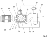
- the Figure 5 illustrates a preferred embodiment of a compressor 64, in particular a rotary compressor, with such a gas inlet valve 1.
- the compressor 64 has a drive motor 65, which is connected by means of a coupling device 66 to compressor screws 67 of the Compressor block 5 is operatively connected.
- the coupling device 66 is designed as a gear or as a force converter.
- the compressor block 5 has two compressor screws 67, which are rotatably mounted in the compressor block 5 by means of bearing devices 68, 69.
- the compressor block 5 preferably has a housing 70 which accommodates the compressor screws 67 and has two housing covers 71, 72 arranged at the ends.
- An oil injection device 73 fluidically connects the oil separator tank to the compressor block 5.
- the compressor screws 67 are lubricated by means of the oil injection device 73.
- the compressor block 5 is fluidically connected to the oil separator tank by means of a gas supply line 74.
- a mixture of compressed gas and oil is preferably supplied to the oil separator tank from the compressor block 5 by means of the gas supply line 74.
- the oil separator tank is also fluidically connected to the second cylinder chamber 52 of the gas inlet valve 1 by means of the working pressure supply line 53.
- the second cylinder chamber 52 can be switchably pressurized with the gas pressure, in particular the working pressure, prevailing in the oil separator tank via the valve 61.
- the oil separator tank 54 can be connected to a compressed air network by means of a connecting flange 75.
- the operation of the compressor 64 is explained below.
- the valve 61 which is preferably designed as a solenoid valve, is open when de-energized.
- the second cylinder chamber 52 is vented and connected to the environment 1 via the working pressure supply line 53.
- the gas inlet valve 1 is closed due to the spring force F F of the spring device 36.
- a start command is first given by a control of the compressor 64.
- the valve 61 initially remains without power.
- the drive motor 65 preferably starts in a star connection.
- the drive motor 65 drives the compressor screws 67 via the coupling device 66. Since the valve body 57 is pressed against its valve seat 56 due to the spring force F F of the spring device 36, a negative pressure is generated in the gas outlet section 4 of the gas inlet valve 1. This negative pressure also acts in the first cylinder chamber 49 due to the fluidic operative connection of the first cylinder chamber 49 with the gas outlet section 4, which is realized by means of the fluid line 39 provided in the piston rod 38.
- the valve body 57 Due to the force ratios between the effective surface of the first piston section 43, on which the force F O acts, the effective surface of the valve body 57, on which the force F U acts, and the spring device 36, which generates the force F F , the valve body 57 remains in contact with the valve seat 56 and the valve device 6 thus remains closed.
- the bridging device 16 is opened at a predetermined gas pressure. A small amount of gas can thus pass through the bridging device 16 past the closed valve device 6 from the gas inlet section 3 into the gas outlet section 4.
- the gas flowing through the bridging device 16 is compressed and fed to the oil separator tank in a mixture with Oil is supplied. This creates a slight overpressure of approximately 1 bar in the oil separator tank. This drives the oil circuit with the oil injection device 73 to lubricate the compressor screws 67.
- the drive motor 65 is switched from star to delta connection. The predetermined period of time depends on the compressor type.
- the control system issues a load command, the valve 61 is energized and opens the working pressure supply line 53 from the oil separator tank to the second cylinder chamber 52.
- the gas pressure of the oil separator tank is now present in the second cylinder chamber 52 and acts against the spring force F F of the spring device 36.
- the opening of the valve device 6, i.e. the lifting of the valve body 57 from its valve seat 56, takes place, for example, immediately, completely or successively.
- both the negative pressure in the gas outlet section 4 and in the first cylinder chamber 49 are reduced to almost zero.
- the gas inlet valve 1 is completely open and the compressor 64 is running at full load.
- the spring force F F of the spring device 36 is sufficient for the valve device 6 to close.
- the compressor 64 is controlled by a proportional controller in the range of approximately 10 to 100% of its delivery quantity.
- the proportional controller is preferably designed as a so-called "negative controller”. This means that as the inlet pressure at the proportional controller increases, its outlet pressure decreases and vice versa.
- the gas inlet valve 1 can be opened continuously by changing, in particular increasing, inlet pressure. Depending on the compressed air requirement, a constant system outlet pressure is thus established at the connection flange 75 of the compressor 64.
- the gas inlet valve 1 described here has a number of advantages. Because the piston device 42 has the first piston section 43 and the second piston section 44 which differs from the first piston section 43, the effective area of the second piston section 44 being significantly smaller than the effective area of the first piston section 43, the second piston section 44 has the advantages of smaller frictional forces, smaller stick-slip effects and a reduced seal diameter.
- the second cylinder chamber 52 of the gas inlet valve 1 described here is also significantly smaller compared to the prior art. Since this second cylinder chamber 52 has to be relieved/vented during switching operations, a smaller volume is advantageous. A small volume of the second cylinder chamber 52 means that the duration of the venting process can be kept short or smaller line cross-sections can be selected for the same venting duration.
- the control pressure of the oil separator tank supports the closing movement of the valve body, in particular when starting the compressor and when switching from full load to idle.
- the gas inlet valve according to the prior art is in the open position due to the gravity of the valve body.
- the gas inlet valve is open. It can only be closed by applying the control pressure.
- a leak or a defect in one of the control lines or a defect in one of the valves can lead to the gas inlet valve no longer closing according to the prior art and the compressor can therefore no longer switch to idle.
- One possible consequence is a pressure increase above the compressor nominal pressure.
- the gas inlet valve 1 described here is closed without pressure due to the spring force F F of the spring device 36.
- the gas pressure of the oil separator tank 54 supports the opening of the valve device 6, i.e. the actuation of the gas inlet valve 1 when switching the compressor 64 from the idle operating state to the full load operating state.
- control of the gas inlet valve 1 described here is comparatively simple compared to the prior art.
- the gas inlet valve 1 can be controlled via the valve 61, which is preferably designed as a 3/2-way valve.
- the following components are not required for controlling the gas inlet valve 1 described here: relief valve, nozzle and/or check valve.
- a single control line in the form of the working pressure supply line 53 is sufficient for controlling the gas inlet valve 1.
Description
Die vorliegende Erfindung bezieht sich auf ein Gaseinlassventil für einen Kompressor, insbesondere für einen Rotationsverdichter, auf einen Kompressor, insbesondere einen Rotationsverdichter, mit einem derartigen Gaseinlassventil sowie auf ein Verfahren zum Betreiben eines Kompressors, insbesondere eines Rotationsverdichters, mit einem derartigen Gaseinlassventil.The present invention relates to a gas inlet valve for a compressor, in particular for a rotary compressor, to a compressor, in particular a rotary compressor, with such a gas inlet valve and to a method for operating a compressor, in particular a rotary compressor, with such a gas inlet valve.
Obwohl die vorliegende Erfindung auf beliebige Kompressoren anwendbar ist, werden die vorliegende Erfindung sowie die ihr zugrunde liegende Problematik in Bezug auf einen Rotationsverdichter näher erläutert.Although the present invention is applicable to any compressor, the present invention and the problem underlying it are explained in more detail with reference to a rotary compressor.
Ein Kompressor wird zumeist direkt gekuppelt oder über ein Getriebe durch einen Kraftwandler angetrieben und verdichtet ein Medium, insbesondere ein Gas, bevorzugt Luft, sobald der Kompressor in Bewegung gesetzt wird. Für die Einrichtung eines Druckluftnetzes beinhaltet diese Funktion jedoch einige Nachteile. In einem modernen Industriebetrieb wird Druckluft für unterschiedlichste Anwendungen genutzt. Je nach Anzahl der am Druckluftnetz angeschlossenen Verbraucher steigt oder sinkt der Druckluftbedarf. Um das geforderte Druckniveau zu halten, wäre der Kompressor deswegen im ständigen Wechsel zwischen Volllast und Stillstand. Eine solche Regelung würde zulasten der Lebensdauer aller angetrieben und antreibenden Bauteile gehen. Hinzu kommt die erhöhte Leistungsaufnahme in der Startphase, welche sich nicht minder auf die Betriebskosten auswirkt. Um dem entgegen zu wirken, kommen in Kompressoren unterschiedlichste Regelungsarten zum Einsatz. Ihre Aufgabe ist die Minimierung des Energieverbrauches und des Verschleißes sowie die Maximierung der Verfügbarkeit. Eine Regeleinheit in einem sogenannten Schraubenkompressor kann ein sogenanntes Gaseinlassventil sein. Dieses ist dem Verdichterblock des Kompressors vorgeschaltet. Das Gaseinlassventil soll eine Rückschlagfunktion, bei der ein Rückströmen von Gas und/oder Fluid aus dem Kompressor in die Umgebung des Kompressors verhindert wird, eine Leerlaufregelung sowie eine Volllastregelung und/oder Proportionalregelung ermöglichen.A compressor is usually directly coupled or driven by a force converter via a gear and compresses a medium, in particular a gas, preferably air, as soon as the compressor is set in motion. However, this function has some disadvantages for the installation of a compressed air network. In a modern industrial plant, compressed air is used for a wide variety of applications. Depending on the number of consumers connected to the compressed air network, the compressed air requirement increases or decreases. In order to maintain the required pressure level, the compressor would therefore be constantly alternating between full load and standstill. Such a regulation would be at the expense of the service life of all driven and driving components. In addition, there is the increased power consumption in the start-up phase, which also has an impact on the operating costs. To counteract this, a wide variety of control types are used in compressors. Their task is to minimize energy consumption and wear and tear and to maximize availability. A control unit in a so-called screw compressor can be a so-called gas inlet valve. This is connected upstream of the compressor block. The gas inlet valve should enable a check function, which prevents gas and/or fluid from flowing back from the compressor into the compressor's surroundings, idle control, full load control and/or proportional control.
Im Falle der Leerlaufregelung des Kompressors darf das Gaseinlassventil lediglich eine bestimmte Menge Luft bzw. Prozessgas in den Verdichter lassen. Diese Maßnahme ist wie folgt zu erklären: Der Anlauf des Verdichters ist aufgrund der Massenträgheit der bewegten Bauteile mit einem erhöhten Energiebedarf gemessen am Volllastbetrieb zu erklären. Um diese Lastspitzen zu minimieren, hilft es, die Arbeit, die beim Verdichten des Mediums verrichtet wird, zu minimieren indem man den Zuluftstrom auf eine minimale Menge reduziert. Hierzu weist das Gaseinlassventil einen federvorgespannten Ventilkörper auf. Dieser wird zum Umschalten von dem Leerlaufbetrieb in den Volllastbetrieb mittels eines druckbeaufschlagten Kolbens entgegen der Federkraft einer den Ventilkörper gegen seinen Ventilsitz pressenden Feder von dem Ventilsitz abgehoben. Ein derartiges Gaseinlassventil mit einem federvorgespannten Ventilkörper ist beispielsweise in der DE 602 10 088 T2 oder in der
Um dies zu vermeiden, schlägt beispielsweise die
Die
Die
Die
Die
Die
Die
Die
Es liegt nun der vorliegenden Erfindung die Aufgabe zugrunde, die obengenannten Nachteile zu beseitigen und ein gegenüber dem Stand der Technik verbessertes Gaseinlassventil zur Verfügung zu stellen.The object of the present invention is to eliminate the above-mentioned disadvantages and to provide a gas inlet valve which is improved compared to the prior art.
Diese Aufgabe wird erfindungsgemäß durch ein Gaseinlassventil mit den Merkmalen des Patentanspruchs 1, durch einen Kompressor mit den Merkmalen des Patentanspruchs 12 und/oder durch ein Verfahren mit den Merkmalen des Patentanspruchs 13 gelöst.This object is achieved according to the invention by a gas inlet valve having the features of
Demgemäß ist ein Gaseinlassventil für einen Kompressor, insbesondere für einen Rotationsverdichter, vorgesehen, mit: einem Gehäuse, welches zum Ansaugen eines Gases einen Gaseinlassabschnitt und zum Leiten des angesaugten Gases zu einem Kompressorblock des Kompressors einen mit dem Gaseinlassab-schnitt bedarfsgemäß fluidisch wirkverbindbaren Gasauslassabschnitt aufweist; einer zwischen dem Gaseinlassabschnitt und dem Gasauslassabschnitt angeordneten Ventileinrichtung mit einem Ventilkörper und mit einem Ventilsitz, wobei der Ventilkörper in einem geschlossenen Betriebszustand der Ventileinrichtung an dem Ventilsitz dichtend anliegt, und wobei der Ventilkörper in einem geöffneten Betriebszustand der Ventileinrichtung von dem Ventilsitz abgehoben ist; einer Kolbeneinrichtung, welche einen ersten Kolbenabschnitt und einen sich von dem ersten Kolbenabschnitt unterscheidenden zweiten Kolbenabschnitt aufweist, wobei der erste Kolbenabschnitt in einem ersten Zylinderabschnitt des Gehäuses und der zweite Kolbenabschnitt in einem sich von dem ersten Zylinderabschnitt unterscheidenden zweiten Zylinderabschnitt des Gehäuses verschieblich geführt ist, wobei der erste Zylinderabschnitt einen Durchmesser DZ1 aufweist, der zweite Zylinderabschnitt einen Durchmesser DZ2 aufweist, der erste Kolbenabschnitt einen Durchmesser DK1 aufweist, welcher auf den Durchmesser DZ1 des ersten Zylinderabschnitts abgestimmt ist, der zweite Kolbenabschnitt einen Durchmesser DK2 aufweist, welcher auf den Durchmesser DZ2 des zweiten Zylinderabschnitts abgestimmt ist, und der Durchmesser DK1 des ersten Kolbenabschnitts größer ist als der Durchmesser DK2 des zweiten Kolbenabschnitts; wobei eine druckbeaufschlagbare Wirkfläche des ersten Kolbenabschnitts mindestens ein 2-faches einer druckbeaufschlagbaren Wirkfläche des zweiten Kolbenabschnittes beträgt; und einer in dem Gehäuse verschieblich gelagerten Kolbenstange welche den Ventilkörper der Ventileinrichtung mit der Kolbeneinrichtung mechanisch koppelt, wobei eine Fluidleitung eine erste Zylinderkammer des ersten Zylinderabschnittes mit dem Gasauslassabschnitt fluidisch wirkverbindet, wobei zum Abheben des Ventilkörpers von dem Ventilsitz eine zweite Zylinderkammer des zweiten Zylinderabschnittes mit einem Steuerdruck beaufschlagbar ist.Accordingly, a gas inlet valve is provided for a compressor, in particular for a rotary compressor, comprising: a housing which has a gas inlet section for sucking in a gas and a gas outlet section for guiding the sucked-in gas to a compressor block of the compressor, which can be fluidically connected to the gas inlet section as required; a valve device arranged between the gas inlet section and the gas outlet section with a valve body and with a valve seat, wherein the valve body is in a closed Operating state of the valve device rests sealingly on the valve seat, and wherein the valve body is lifted off the valve seat in an open operating state of the valve device; a piston device which has a first piston section and a second piston section which differs from the first piston section, wherein the first piston section is displaceably guided in a first cylinder section of the housing and the second piston section is displaceably guided in a second cylinder section of the housing which differs from the first cylinder section, wherein the first cylinder section has a diameter DZ1, the second cylinder section has a diameter DZ2, the first piston section has a diameter DK1 which is matched to the diameter DZ1 of the first cylinder section, the second piston section has a diameter DK2 which is matched to the diameter DZ2 of the second cylinder section, and the diameter DK1 of the first piston section is larger than the diameter DK2 of the second piston section; wherein a pressurizable effective area of the first piston section is at least twice a pressurizable effective area of the second piston section; and a piston rod which is slidably mounted in the housing and which mechanically couples the valve body of the valve device to the piston device, wherein a fluid line fluidically connects a first cylinder chamber of the first cylinder section to the gas outlet section, wherein a second cylinder chamber of the second cylinder section can be subjected to a control pressure in order to lift the valve body off the valve seat.
Ferner ist ein Kompressor, insbesondere ein Rotationsverdichter, mit einem derartigen Gaseinlassventil vorgesehen.Furthermore, a compressor, in particular a rotary compressor, with such a gas inlet valve is provided.
Noch ferner ist ein Verfahren zum Betreiben eines Kompressors, insbesondere eines Rotationsverdichters, mit einem erfindungsgemäßen Gaseinlassventil vorgesehen, mit folgenden Verfahrensschritten: Starten eines Antriebsmotors des Kompressors und Erzeugen eines Unterdrucks in dem Gasauslassabschnitt des Gaseinlassventils, wobei die Ventileinrichtung geschlossen ist; druckgesteuertes Öffnen der Überbrückungseinrichtung mittels des in dem Gasauslassabschnitt herrschenden Unterdrucks zum Leiten des angesaugten Gases über die Überbrückungseinrichtung von dem Gaseinlassabschnitt zu dem Gasauslassabschnitt; Verdichten des angesaugten Gases im Kompressorblock; Freischalten einer Arbeitsdruckzufuhrleitung zwischen einem Druckraum des Kompressors und einer zweiten Zylinderkammer des Gaseinlassventils; und Öffnen der Ventileinrichtung mittels der druckbeaufschlagten zweiten Zylinderkammer.A method for operating a compressor, in particular a rotary compressor, with a gas inlet valve according to the invention is also provided, comprising the following method steps: starting a drive motor of the compressor and generating a negative pressure in the gas outlet section of the gas inlet valve, the valve device being closed; pressure-controlled opening of the bridging device by means of the negative pressure prevailing in the gas outlet section for guiding the sucked-in gas via the bridging device from the gas inlet section to the gas outlet section; compressing the sucked-in gas in the compressor block; releasing a working pressure supply line between a pressure chamber of the compressor and a second cylinder chamber of the gas inlet valve; and opening the valve device by means of the pressurized second cylinder chamber.
Die der vorliegenden Erfindung zugrunde liegende Idee besteht darin, die Kolbeneinrichtung mit einem ersten Kolbenabschnitt und mit einem sich von dem ersten Kolbenabschnitt unterscheidenden zweiten Kolbenabschnitt auszugestalten. Dabei wird die erste Zylinderkammer über die Fluidleitung stets mit dem im Gasauslassabschnitt anliegenden Gasdruck beaufschlagt. Dadurch, dass der Ventilkörper über die Kolbenstange mit der Kolbeneinrichtung gekoppelt ist, wird der Ventilkörper in dem Leerlauf-Betriebszustand, indem in dem Gasauslassabschnitt ein Unterdruck herrscht, gegen seinen Ventilsitz gepresst. Eine kräftig dimensionierte Ventilfeder zur Verwirklichung des Leerlauf-Betriebszustandes ist somit verzichtbar. Ferner ist zum Öffnen der Ventileinrichtung lediglich die zweite Zylinderkammer mit einem Arbeitsdruck zu beaufschlagen. Ein komplexes und fein abgestimmtes Pneumatiksystem ist daher für eine zuverlässige Funktion des Gaseinlassventils verzichtbar.The idea underlying the present invention is to design the piston device with a first piston section and with a second piston section that differs from the first piston section. The first cylinder chamber is always subjected to the gas pressure present in the gas outlet section via the fluid line. Because the valve body is coupled to the piston device via the piston rod, the valve body is pressed against its valve seat in the idle operating state in which a negative pressure prevails in the gas outlet section. A powerfully dimensioned valve spring for implementing the idle operating state is therefore Furthermore, only the second cylinder chamber needs to be subjected to working pressure to open the valve device. A complex and finely tuned pneumatic system is therefore not necessary for the gas inlet valve to function reliably.
Vorteilhafte Ausgestaltungen und Weiterbildungen der Erfindung ergeben sich aus den weiteren Unteransprüchen sowie aus der Beschreibung in Zusammenschau mit den Figuren der Zeichnung.Advantageous embodiments and further developments of the invention emerge from the further subclaims and from the description in conjunction with the figures of the drawing.
Gemäß einer bevorzugten Ausgestaltung des Gaseinlassventils weist die Kolbenstange die Fluidleitung auf, wobei die Fluidleitung insbesondere als in der Kolbenstange verlaufender Fluidkanal ausgebildet ist. Vorzugsweise ist die Fluidleitung als zentrisch in der Kolbenstange verlaufende Durchgangsbohrung ausgebildet. Alternativ ist die Fluidleitung als in dem Gehäuse, insbesondere in einer Wandung des Gehäuses, verlaufender Fluidkanal ausgebildet. Durch das Vorsehen der Fluidleitung in der Kolbenstange ergibt sich ein besonders kurzer Strömungsweg mit geringem Strömungswiderstand. Durch das Vorsehen der Fluidleitung in dem Gehäuse ergibt sich eine besonders kostengünstige Herstellbarkeit der Kolbenstange.According to a preferred embodiment of the gas inlet valve, the piston rod has the fluid line, wherein the fluid line is designed in particular as a fluid channel running in the piston rod. The fluid line is preferably designed as a through-hole running centrally in the piston rod. Alternatively, the fluid line is designed as a fluid channel running in the housing, in particular in a wall of the housing. The provision of the fluid line in the piston rod results in a particularly short flow path with low flow resistance. The provision of the fluid line in the housing results in the piston rod being particularly cost-effective to manufacture.
Gemäß einer bevorzugten Ausgestaltung des Gaseinlassventils weist dieses eine Federeinrichtung auf, welche die Kolbeneinrichtung in Richtung eines Gehäusedeckels des Gehäuses federvorspannt. Insbesondere ist die Federeinrichtung zwischen der Kolbeneinrichtung und einer Gegenfläche des Gehäuses (Ventildom) angeordnet, wobei die Federeinrichtung den Ventilkörper über die mechanische Kopplung der Kolbeneinrichtung und des Ventilkörpers mittels der Kolbenstange gegen ihren Ventilsitz federvorspannt. Hierdurch ist in einem Stillstand des Kompressors gewährleistet, dass die Ventileinrichtung vollständig geschlossen ist. Hierdurch ist es möglich, die beweglichen Komponenten des Gaseinlassventils vertikal zu positionieren, wodurch ein verringerter Verschleiß der Lagerstellen erzielt wird. Vorzugsweise ist die Federeinrichtung dazu ausgelegt, zumindest ein Eigengewicht der Kolbeneinrichtung und der Kolbenstange zu tragen. Insbesondere kann die Federeinrichtung dazu ausgelegt sein, zusätzlich ein Eigengewicht des Ventilkörpers und/oder einer Feder der Ventileinrichtung zu tragen. Im Ergebnis kann eine Federeinrichtung mit einer geringen Federsteifigkeit gewählt und mit einer geringen Federvorspannung montiert werden. Hierdurch wird die Montage der Federeinrichtung vereinfacht.According to a preferred embodiment of the gas inlet valve, the latter has a spring device which pre-tensions the piston device in the direction of a housing cover of the housing. In particular, the spring device is arranged between the piston device and a counter surface of the housing (valve dome), wherein the spring device presses the valve body via the mechanical Coupling of the piston device and the valve body by means of the piston rod spring-loaded against its valve seat. This ensures that the valve device is completely closed when the compressor is at a standstill. This makes it possible to position the movable components of the gas inlet valve vertically, thereby reducing wear on the bearing points. Preferably, the spring device is designed to bear at least a dead weight of the piston device and the piston rod. In particular, the spring device can be designed to additionally bear a dead weight of the valve body and/or a spring of the valve device. As a result, a spring device with a low spring stiffness can be selected and mounted with a low spring preload. This simplifies the assembly of the spring device.
Gemäß einer bevorzugten Ausführungsform des Gaseinlassventils weist dieses eine Überbrückungseinrichtung auf, welche bedarfsgemäß, insbesondere in einem Leerlauf-Betriebszustand des Gaseinlassventils, unter Überbrückung der geschlossenen Ventileinrichtung den Gaseinlassabschnitt mit dem Gasauslassabschnitt fluidisch wirkverbindet, wobei die Überbrückungseinrichtung vorzugsweise dazu ausgelegt ist nach dem Wirkprinzip eines Rückschlagventils zu wirken. Über die Überbrückungseinrichtung wird im Leerlauf-Betriebszustand eine erforderliche (geringe) Leerlauf-Luftmenge angesaugt. Dies ermöglicht mit einer einfachen technischen Maßnahme die Zufuhr eines reduzierten Zuluftstromes bei einem Leerlauf des Kompressors. Hierdurch wird der Aufbau des Gaseinlassventils vereinfacht.According to a preferred embodiment of the gas inlet valve, it has a bridging device which, as required, in particular in an idle operating state of the gas inlet valve, fluidically connects the gas inlet section to the gas outlet section by bridging the closed valve device, wherein the bridging device is preferably designed to work according to the principle of a check valve. In the idle operating state, a required (small) idle air quantity is sucked in via the bridging device. This enables the supply of a reduced supply air flow when the compressor is idling with a simple technical measure. This simplifies the structure of the gas inlet valve.
Gemäß einer weiteren bevorzugten Ausführungsform ist eine Wirkfläche des ersten Kolbenabschnittes größer als eine Wirkfläche des zweiten Kolbenabschnittes ausgebildet. Vorzugsweise ist die Wirkfläche des ersten Kolbenabschnittes um mindestens einen Faktor 15 größer als die Wirkfläche des zweiten Kolbenabschnittes ausgebildet. Insbesondere ist die Wirkfläche des ersten Kolbenabschnittes um einen Faktor 30 größer als die Wirkfläche des zweiten Kolbenabschnittes ausgebildet. Insbesondere entspricht die Wirkfläche des ersten Kolbenabschnittes einem 0,7 bis 1,5-fachen, insbesondere einem 1 bis 1,1-fachen, einer Wirkfläche des Ventilkörpers. Vorzugsweise entspricht die Wirkfläche des ersten Kolbenabschnittes einem 1,05-fachen der Wirkfläche des Ventilkörpers. Durch die Abstimmung der Wirkflächen aufeinander ist vorteilhaft die Federeinrichtung möglichst klein dimensionierbar, wodurch der Montageaufwand zur Montage des Gaseinlassventils reduziert wird.According to a further preferred embodiment, an effective area of the first piston section is larger than an effective area of the second piston section. The effective area of the first piston section is preferably at least 15 times larger than the effective area of the second piston section. In particular, the effective area of the first piston section is 30 times larger than the effective area of the second piston section. In particular, the effective area of the first piston section corresponds to 0.7 to 1.5 times, in particular 1 to 1.1 times, an effective area of the valve body. The effective area of the first piston section preferably corresponds to 1.05 times the effective area of the valve body. By matching the effective areas to one another, the spring device can advantageously be dimensioned as small as possible, which reduces the assembly effort for mounting the gas inlet valve.
Gemäß einer weiteren bevorzugten Ausgestaltung des Gaseinlassventils sind eine Wirkfläche des ersten Kolbenabschnittes und eine Wirkfläche des Ventilkörpers derart dimensioniert, dass die Ventileinrichtung bei entlüfteter zweiter Zylinderkammer unabhängig von einem Betriebszustand des Kompressors infolge von auf den ersten Kolbenabschnitt und den Ventilkörper wirkenden Kräften und infolge einer auf den Ventilkörper wirkenden Federkraft der Federeinrichtung in ihrem geschlossenen Betriebszustand verbleibt. Der Kompressor kann sich beispielsweise in einem Last-, Leerlauf- oder Stillstand-Betriebszustand befinden. Insbesondere kann die Ventileinrichtung lediglich mittels einem Anlegen eines Steuerdruckes an die zweite Zylinderkammer geöffnet werden. Hierdurch befindet sich die Ventileinrichtung in einem entlüfteten Zustand der zweiten Zylinderkammer stets in ihrem geschlossenen Betriebszustand.According to a further preferred embodiment of the gas inlet valve, an effective surface of the first piston section and an effective surface of the valve body are dimensioned such that the valve device, when the second cylinder chamber is vented, remains in its closed operating state regardless of the operating state of the compressor as a result of forces acting on the first piston section and the valve body and as a result of a spring force of the spring device acting on the valve body. The compressor can, for example, be in a load, idle or standstill operating state. In particular, the valve device can be opened only by applying a control pressure to the second cylinder chamber. As a result, the Valve device in a vented state of the second cylinder chamber always in its closed operating state.
Gemäß einer weiteren bevorzugten Ausgestaltung des Gaseinlassventils ist der Ventilkörper verschieblich auf der Kolbenstange gelagert. Im Falle einer plötzlichen Unterbrechung des Verdichtungsvorganges durch den Kompressor, beispielsweise in einem Not-Aus-Betriebszustand desselben, baut sich zeitverzögert ein Druck unterhalb des Ventilkörpers auf (Rückströmung). Dadurch, dass der Ventilkörper verschieblich auf der Kolbenstange gelagert ist, wird dieser aufgrund des herrschenden Druckes in dem Gasauslassabschnitt über seinen gesamten Hubweg in Bruchteilen einer Sekunde in Richtung des Ventilsitzes angehoben und gegen den Ventilsitz der Ventileinrichtung gepresst. Hierdurch wird eine Rückschlagfunktion verwirklicht, die zuverlässig verhindert, dass Gas und/oder Öl von dem Gasauslassabschnitt zurück in den Gaseinlassabschnitt strömen kann.According to a further preferred embodiment of the gas inlet valve, the valve body is slidably mounted on the piston rod. In the event of a sudden interruption of the compression process by the compressor, for example in an emergency stop mode, a pressure builds up below the valve body with a time delay (backflow). Because the valve body is slidably mounted on the piston rod, it is raised in the direction of the valve seat over its entire stroke in fractions of a second due to the prevailing pressure in the gas outlet section and pressed against the valve seat of the valve device. This creates a check function that reliably prevents gas and/or oil from flowing back from the gas outlet section into the gas inlet section.
Gemäß einer bevorzugten Ausführungsform des Gaseinlassventils weist die Ventileinrichtung eine Feder auf, welche zwischen einem Begrenzungselement der Kolbenstange und dem Ventilkörper angeordnet ist. Insbesondere ist die Feder dazu ausgelegt, ein Eigengewicht des Ventilkörpers zu tragen. Im geschilderten Fall eines Blockstillstandes, d.h. der plötzlichen Unterbrechung des Verdichtungsvorganges, reißt die Strömung vom Ansaugfilter des Kompressors durch das Gaseinlassventil zum Kompressorblock ab. Bevor das rückströmende verdichtete Gas den Ventilkörper erreicht, hat die Feder diesen inzwischen schon beinah bis zum Ventilsitz angehoben. Bei eintretender Rückschlagfunktion ist der Weg des Ventilkörpers zu dem Ventilsitz relativ klein. Die Aufschlagkräfte beim Auftreffen des Ventilkörpers auf den Ventilsitz erweisen sich dadurch dementsprechend gering. Hierdurch wird ein übermäßiger Verschleiß des Ventilkörpers unterbunden, wodurch die Lebensdauer des Gaseinlassventils erhöht wird.According to a preferred embodiment of the gas inlet valve, the valve device has a spring which is arranged between a limiting element of the piston rod and the valve body. In particular, the spring is designed to bear the weight of the valve body. In the described case of a block standstill, ie the sudden interruption of the compression process, the flow from the intake filter of the compressor through the gas inlet valve to the compressor block breaks off. Before the compressed gas flowing back reaches the valve body, the spring has already lifted it almost to the valve seat. When the check function occurs, the path of the valve body to the valve seat is relatively small. The The impact forces when the valve body hits the valve seat are therefore correspondingly low. This prevents excessive wear on the valve body, which increases the service life of the gas inlet valve.
Gemäß einer bevorzugten Ausführungsform des Verfahrens wird die Kolbeneinrichtung bei dem Öffnen der Ventileinrichtung gegen eine Federkraft der Federeinrichtung bewegt.According to a preferred embodiment of the method, the piston device is moved against a spring force of the spring device when the valve device is opened.
Gemäß einer weiteren bevorzugten Ausführungsform des Verfahrens werden eine Wirkfläche des ersten Kolbenabschnittes und eine Wirkfläche des Ventilkörpers derart dimensioniert, dass die Ventileinrichtung bei entlüfteter zweiter Zylinderkammer unabhängig von einem Betriebszustand des Kompressors infolge von auf den ersten Kolbenabschnitt und den Ventilkörper wirkenden Kräften und infolge einer auf den Ventilkörper wirkenden Federkraft der Federeinrichtung in ihrem geschlossenen Betriebszustand verbleibt und dass die Ventileinrichtung lediglich mittels einem Anlegen eines Steuerdruckes an die zweite Zylinderkammer geöffnet wird. Hierdurch wird die Ventileinrichtung in einem entlüfteten Zustand der zweiten Zylinderkammer stets in ihren geschlossenen Betriebszustand verbracht.According to a further preferred embodiment of the method, an effective surface of the first piston section and an effective surface of the valve body are dimensioned such that the valve device remains in its closed operating state when the second cylinder chamber is vented, regardless of an operating state of the compressor, as a result of forces acting on the first piston section and the valve body and as a result of a spring force of the spring device acting on the valve body, and that the valve device is only opened by applying a control pressure to the second cylinder chamber. As a result, the valve device is always brought into its closed operating state when the second cylinder chamber is vented.
Die Erfindung wird im Folgenden anhand von Ausführungsbeispielen unter Bezugnahme auf die beiliegenden Figuren der Zeichnung näher erläutert.The invention is explained in more detail below using embodiments with reference to the accompanying figures of the drawing.
Von den Figuren zeigen:
Figur 1- eine Querschnittsansicht einer bevorzugten Ausführungsform eines Gaseinlassventils in einem Leerlauf-Betriebszustand;
Figur 2- eine Querschnittsansicht einer bevorzugten Ausführungsform einer Kolbeneinrichtung des Gaseinlassventils gemäß
Figur 1 ; Figur 3- eine Querschnittsansicht des Gaseinlassventils gemäß
Figur 1 in einem Lastlauf-Betriebszustand; Figur 4- eine Querschnittsansicht des Gaseinlassventils gemäß
Figur 1 in einer Rückschlagstellung; und Figur 5- eine Querschnittsansicht einer bevorzugten Ausführungsform eines Kompressors mit einem Gaseinlassventil gemäß
Figur 1
- Figure 1
- a cross-sectional view of a preferred embodiment of a gas inlet valve in an idle operating state;
- Figure 2
- a cross-sectional view of a preferred embodiment of a piston device of the gas inlet valve according to
Figure 1 ; - Figure 3
- a cross-sectional view of the gas inlet valve according to
Figure 1 in a load running operating condition; - Figure 4
- a cross-sectional view of the gas inlet valve according to
Figure 1 in a setback position; and - Figure 5
- a cross-sectional view of a preferred embodiment of a compressor with a gas inlet valve according to
Figure 1 .
In den Figuren der Zeichnung bezeichnen dieselben Bezugszeichen gleiche oder funktionsgleiche Komponenten, soweit nichts Gegenteiliges angegeben ist.In the figures of the drawing, the same reference symbols designate identical or functionally identical components, unless otherwise stated.
Die
Das Gaseinlassventil 1 weist ein Gehäuse 2 mit einem Gaseinlassabschnitt 3 und mit einem Gasauslassabschnitt 4 auf. Der Gaseinlassabschnitt 3 ist zum Ansaugen eines Gases, beispielsweise Umgebungsluft ausgebildet. Das Gas kann unkomprimiert oder bereits vorverdichtet sein. Der Gasauslassabschnitt 4 ist zum Weiterleiten des mittels des Gaseinlassabschnitt 3 angesaugten Gases zu einem Kompressorblock 5 des Kompressors ausgebildet. Der Gaseinlassabschnitt 3 und der Gasauslassabschnitt 4 können mittels einer zwischen dem Gaseinlassabschnitt 3 und dem Gasauslassabschnitt 4 angeordneten Ventileinrichtung 6 bedarfsgemäß voneinander fluidisch getrennt oder miteinander fluidisch verbunden werden.The
Das Gehäuse 2 weist vorzugsweise einen ersten hohlzylinderförmigen Gehäuseabschnitt 7 auf. Die Ventileinrichtung 6 ist vorzugsweise an einem ersten Endabschnitt des ersten Gehäuseabschnittes 7 angeordnet. Der erste Gehäuseabschnitt 7 weist einen Blockanschlussflansch 8 mit einer im Wesentlichen ringförmigen Anschraubfläche 9 auf. Die Anschraubfläche 9 liegt vorzugsweise flächig auf dem Kompressorblock 5 auf. Mittels Verbindungselementen ist der Blockanschlussflansch 8 mit dem Kompressorblock 5 kraft- und/oder formschlüssig wirkverbunden. Zwischen der Anschraubfläche 9 und dem Kompressorblock 5 ist vorzugsweise eine Dichteinrichtung, beispielsweise ein O-Ring angeordnet. Die Verbindungselemente sind beispielsweise als Schrauben ausgebildet. Die Anschraubfläche 9 bildet beispielsweise eine x/y-Ebene des ersten Gehäuseabschnittes 7 bzw. des Gehäuses 2, zu welcher senkrecht eine z-Achse oder Hochrichtung des Gehäuses 2 positioniert ist. Eine Mittelachse 10 des ersten Gehäuseabschnittes 7 bzw. des Gehäuses 2 verläuft bevorzugt in z-Richtung. Die Mittelachse 10 kann alternativ in einem Winkel von etwa 45° bis 90° zu der Anschraubfläche 9 angeordnet sein. Andere Einbaulagen des Verdichterblocks, bzw. der Anschraubfläche sind ebenfalls denkbar. Die Anschraubfläche 9 kann an beliebiger Position des ersten Gehäuseabschnittes 7 und/oder in einem beliebigen Winkel zur Mittelachse 10 des ersten Gehäuseabschnittes 7 angeordnet seinThe
Der erste Gehäuseabschnitt 7 weist ferner ein optionales, integral mit dem ersten Gehäuseabschnitt 7 ausgebildetes, hohlzylinderförmiges Gussauge 11 auf, welches vorzugsweise in einem unteren, d.h. dem Gasauslassabschnitt 4 zugeordneten Bereich des ersten Zylinderabschnittes 7 angeordnet ist. Das Gussauge 11 kann alternativ an einer beliebigen Position an dem Gehäuse 2 angeordnet sein. Eine Mittelachse 12 des Gussauges 11 ist vorzugsweise im Wesentlichen senkrecht zu der Mittelachse 10 des Gehäuses 2 angeordnet. Das Gussauge 11 ist vorzugsweise mit einer entlang der Mittelachse 12 verlaufenden zentrischen Stufenbohrung 13 versehen, welche den ersten Zylinderabschnitt 7 durchbricht und den Gaseinlassabschnitt 3 mit der Umgebung 14 des Einlassventils 1 verbindet. Zum gasdichten Abschließen der Stufenbohrung 13 zu der Umgebung 14 hin ist eine Verschlussschraube 15 einer im Folgenden noch zu erläuternden Überbrückungseinrichtung 16 vorgesehen. Die Stufenbohrung 13 weist dabei vorzugsweise in dem Gussauge 11 verlaufend einen größeren Bohrungsdurchmesser auf als in dem ersten Gehäuseabschnitt 7. Außen an dem ersten Gehäuseabschnitt 7, d.h. zu dem Gussauge 11 hin ist die Stufenbohrung 13 vorzugsweise umlaufend mit einem Ventilsitz 17 versehen. Die Stufenbohrung 13 ist mittels einer weiteren, im Wesentlichen in z-Richtung verlaufenden Öffnung, insbesondere einer Bohrung 18, mit dem Gasauslassabschnitt 4 fluidisch wirkverbunden.The
Die Überbrückungseinrichtung 16 weist neben der Bohrung 18, der Stufenbohrung 13 und der Verschlussschraube 15 vorzugsweise einen im Wesentlichen zylindrischen Ventilkolben 19, welcher verschieblich in der Stufenbohrung 13 angeordnet ist, und eine Feder 20, insbesondere eine Druckfeder 20, auf. Der Ventilkolben 19 ist vorzugsweise mittels der zwischen demselben und der Verschlussschraube 15 angeordneten Druckfeder 20 in Richtung des ersten Gehäuseabschnittes 7 federvorgespannt. Dabei liegt in einem geschlossenen Betriebszustand der Überbrückungseinrichtung 16 ein Dichtabschnitt 21 des Ventilkolbens 19 dichtend an dem Ventilsitz 17 der Stufenbohrung 13 an und unterbindet einen Gasstrom von dem Gaseinlassabschnitt 3 zu dem Gasauslassabschnitt 4 über die Überbrückungseinrichtung 16. Die Druckfeder 20 ist vorzugsweise zumindest abschnittsweise in einer zentrischen Ausnehmung des Ventilkolbens 19 angeordnet. Eine Federsteifigkeit der Druckfeder 20 ist vorzugsweise derart ausgelegt, dass der Dichtabschnitt 21 bei dem Wirken eines vorbestimmten Gasdruckes gegen die Federkraft der Druckfeder 20 von dem Ventilsitz 17 der Stufenbohrung 13 abgehoben wird und so ein Gasfluss von dem Gaseinlassabschnitt 3 zu dem Gasauslassabschnitt 4 über die Überbrückungseinrichtung 16 möglich ist. Der vorbestimmte Gasdruck wird durch einen Überdruck im Gaseinlassabschnitt 3 gegenüber dem Gasauslassabschnitt 4 gebildet. Wirkt ein Gasdruck, welcher kleiner ist als der vorbestimmte Gasdruck so drückt die Druckfeder 20 den Dichtabschnitt 21 des Ventilkolbens 19 gegen den Ventilsitz 17. Beispielsweise befindet sich die Überbrückungseinrichtung 16 in dem geschlossenen Betriebszustand wenn ein Überdruck im Gasauslassabschnitt 4 gegenüber dem Gaseinlassabschnitt 3 herrscht oder im Gasauslassabschnitt 4 und im Gaseinlassabschnitt 3 ein gleicher Gasdruck herrscht.In addition to the
An einem dem ersten Endabschnitt abgewandten zweiten Endabschnitt des ersten Gehäuseabschnittes 7 ist ein erster Zylinderabschnitt 22 vorgesehen. Der erste Zylinderabschnitt 22 ist vorzugsweise als bearbeitete Oberfläche in dem hohlzylinderförmigen ersten Gehäuseabschnitt 7 vorgesehen. Vorzugsweise weist der erste Zylinderabschnitt 22 einen Durchmesser DZ1 und eine Länge l1 auf. In einer bevorzugten Ausführungsform des Gaseinlassventils 1 begrenzt ein bevorzugt umlaufender Absatz 23 den ersten Zylinderabschnitt 22 insbesondere nach unten hin, d.h. in Richtung der Ventileinrichtung 6. Nach oben hin ist der erste Zylinderabschnitt 22 durch einen den ersten Gehäuseabschnitt 7 abschließenden Gehäusedeckel 24 des Gehäuses 2 begrenzt. Der Gehäusedeckel 24 ist vorzugsweise scheibenförmig ausgebildet mit einer mittigen in etwa zylinderförmigen Auswölbung 25, deren Mittelachse vorzugsweise der Mittelachse 10 des ersten Gehäuseabschnittes 7 entspricht. Alternativ kann die Auswölbung 25 exzentrisch zu der Mittelachse 10 angeordnet sein. Der Gehäusedeckel 24 liegt vorzugsweise ringförmig auf einem Anschlussflansch 26 des ersten Gehäuseabschnittes 7 auf und ist mit diesem vorzugsweise kraft- und/oder formschlüssig mittels Verbindungselementen, insbesondere Schrauben, wirkverbunden. Zum Zentrieren des Gehäusedeckels 24 an dem Anschlussflansch 26 kann dieser vorzugsweise einen umlaufenden Zentrierbund aufweisen. Zwischen dem Gehäusedeckel 24 und dem Anschlussflansch 26 ist vorzugsweise eine Dichteinrichtung, beispielsweise ein O-Ring, vorgesehen.A
Der Gehäusedeckel 24 weist vorzugsweise eine koaxial zu der Mittelachse 10 angeordnete, sich in die Auswölbung 25 erstreckende Zylinderbohrung auf, welche insbesondere als zweiter Zylinderabschnitt 27 des Gaseinlassventils 1 ausgebildet ist. Der zweite Zylinderabschnitt 27 kann mittels einer Buchse, insbesondere einer Gleitbuchse, ausgebildet sein. Der zweite Zylinderabschnitt 27 dringt bevorzugt von der Seite des ersten Gehäuseabschnittes 7 aus mit einer Tiefe l2 in den Gehäusedeckel 24 ein. Der zweite Zylinderabschnitt 27 des Gaseinlassventils 1 weist einen Durchmesser DZ2 auf. In Bezug auf die Zylinderbohrung mittig ist eine Arbeitsdruckzuführbohrung 28 vorgesehen, welche vorzugsweise den von der Zylinderbohrung nicht durchbrochenen Anteil der Auswölbung 25 durchbricht.The
Ein zweiter, im Wesentlichen hohlzylindrischer Gehäuseabschnitt 29 des Gehäuses 2 ist vorzugsweise integral mit dem ersten Gehäuseabschnitt 7 ausgebildet und durchdringt diesen bevorzugt zumindest abschnittsweise. Eine Mittelachse 30 des zweiten Gehäuseabschnittes 29 ist vorzugsweise in einem Winkel α zu der Mittelachse 10 positioniert. Der Winkel α weist beispielsweise einen Wert von in etwa 90°, insbesondere von in etwa 60°, auf. Der zweite Gehäuseabschnitt 29 ist bevorzugt derart ausgebildet, dass ein erster, aus dem ersten Gehäuseabschnitt 7 herausragender Endabschnitt desselben als Flanschabschnitt 31 zum Anschließen einer Gaszufuhrleitung an das Gaseinlassventil 1 ausgebildet ist. Die Gaszufuhrleitung kann beispielsweise mittels einer Klemmschelle an dem Flanschabschnitt 31 montiert sein. Ein zweiter Endabschnitt des zweiten Gehäuseabschnittes 29 geht vorzugsweise in den ersten Endabschnitt des ersten Gehäuseabschnittes 7 über. Der zweite Gehäuseabschnitt 29 ist vorzugsweise zumindest abschnittsweise derart als Ansaugumlenkung ausgebildet, dass das in dem Gehäuse 2 von dem Gaseinlassabschnitt 3 zugeführte Gas bogenförmig und somit strömungsoptimiert zu dem Gasauslassabschnitt 4 geführt wird. Ein oberer Wandabschnitt 32 des zweiten Gehäuseabschnittes 29 trennt den Gaseinlassabschnitt 3 von einem Innenraum 33 des ersten Gehäuseabschnittes 7 ab.A second, essentially hollow-
Im Wesentlichen zentral im Gehäuse 2 ist ein, insbesondere zylinderförmiger, Ventildom 34 mit einer in Bezug auf den ersten Gehäuseabschnitt 7 mittigen, in Richtung der Mittelachse 10 verlaufenden Durchgangsbohrung 35 vorgesehen. Der Ventildom 34 ist vorzugsweise integral mit dem oberen Wandabschnitt 32 ausgebildet. In die Durchgangsbohrung 35 kann eine als Gleitlager wirkende Buchse eingepresst sein. Der Ventildom 34 dient insbesondere als Anlagefläche für eine Federeinrichtung 36 bzw. Feder 36, insbesondere Druckfeder 36. Vorzugsweise im Strömungsschatten des Ventildoms 34 ist ein Durchbruch 37 vorgesehen, welcher den Innenraum 33 mit dem Gaseinlassabschnitt 3 fluidisch verbindet. Alternativ oder zusätzlich kann der Innenraum 33 mittels eines Durchbruches direkt mit der Umgebung 14 fluidisch wirkverbunden sein. Hierdurch herrscht in dem Innenraum 33 und in dem Gaseinlassabschnitt 3 stets im Wesentlichen derselbe Gasdruck. Unter im Wesentlichen derselbe Gasdruck ist zu verstehen, dass geringfügige Druckunterschiede zwischen dem Innenraum 33 und dem Gaseinlassabschnitt 3 bestehen können. Das Gehäuse 2, d.h. die Gehäuseabschnitte 7, 29 und der Gehäusedeckel 24 sind vorzugsweise als Gussbauteile mit spanend bearbeiteten Funktionsflächen ausgebildet. Die Gehäuseabschnitte 7, 29 sind vorzugsweise einstückig ausgeführt.A
In dem Gehäuse 2, insbesondere in dem Ventildom 34, ist eine Kolbenstange 38 in z-Richtung, d.h. entlang der Mittelachse 10 verschieblich gelagert. Die Kolbenstange 38 ist vorzugsweise als Hohlzylinder mit einer die Kolbenstange 38 insbesondere auf ihrer gesamten Länge durchdringenden zentralen Fluidleitung 39 ausgeführt. Die Fluidleitung 39 ist vorzugsweise als die Kolbenstange 38 auf ihrer gesamten Länge durchdingender Fluidkanal, insbesondere als Durchgangsbohrung ausgebildet. Dem Gasauslassabschnitt 4 ist ein erster Endabschnitt 40 der Kolbenstange 38 zugeordnet. Ein zweiter Endabschnitt 41 der Kolbenstange 38 ist dem Gasauslassabschnitt 4 abgewandt. Die Fluidleitung 39 ist im Bereich des ersten Endabschnittes 40 fluidisch mit dem Gasauslassabschnitt 4 wirkverbunden. Die Fluidleitung 39 kann alternativ als ein in dem Gehäuse 2, insbesondere in einer Wandung des Gehäuses 2, verlaufender Fluidkanal ausgebildet sein.In the
Das Gaseinlassventil 1 weist vorzugsweise eine in
Vom Gasauslassabschnitt 4 weg in Richtung des Gehäusedeckels 24 ist der Weg des ersten Kolbenabschnittes 43 dadurch begrenzt, dass die Kolbeneinrichtung 42 mittels der mit dieser wirkverbundenen Kolbenstange 38 über deren ersten Endabschnitt 40 mit einem Ventilkörper 57 der Ventileinrichtung 6 gekoppelt ist. Die Federeinrichtung 36 drückt die Kolbeneinrichtung 42 in Richtung des Gehäusedeckels 24. Hierdurch wird der Ventilkörper 57 gegen einen Ventilsitz 56 federvorgespannt. Aufgrund der mechanischen Kopplung des Ventilkörpers 57 mit der Kolbeneinrichtung 42 kann durch eine entsprechende Abstimmung der Länge der Kolbenstange 42 erreicht werden, dass der erste Kolbenabschnitt 43 stets zumindest einen minimalen Abstand von dem Gehäusedeckel 24 aufweist. Bevorzugt berührt der erste Kolbenabschnitt 43 den Gehäusedeckel 24 nie. Umfänglich zu dem ersten Zylinderabschnitt 22 hin kann der erste Kolbenabschnitt 43 mit einer an einer Mantelfläche 45 desselben umlaufend vorgesehenen ersten Labyrinthdichtung, insbesondere einer Durchblicklabyrinthdichtung, versehen sein. Zum Gehäusedeckel 24 hin kann der erste Kolbenabschnitt 43 zusätzlich oder optional mittels einer umlaufenden zweiten Labyrinthdichtung abgedichtet sein. Die zweite Labyrinthdichtung kann als sogenannte Volllabyrinthdichtung ausgebildet sein, wobei vorzugsweise in eine dem Gehäusedeckel 24 zugewandte Stirnfläche 46 des ersten Kolbenabschnittes 43 sowie in den Gehäusedeckel 24 ineinandergreifende Labyrinthkammern eingearbeitet sind. Der erste Kolbenabschnitt 43 kann alternativ oder zusätzlich mit einem O-Ring, Kolbenring, Nutring oder dergleichen gegen den ersten Zylinderabschnitt 22 abgedichtet sein. Bei entsprechender Ausgestaltung der Passung zwischen dem ersten Kolbenabschnitt 43 und dem ersten Zylinderabschnitt 22 kann eine Dichteinrichtung verzichtbar sein. Der erste Kolbenabschnitt 43 weist einen sich in Richtung des Ventildoms 34 ersteckenden zylinderförmigen Anschlussabschnitt 47 mit einer mittigen Bohrung 48 auf. Die Bohrung 48 kann alternativ exzentrisch angeordnet sein. Die Bohrung 48 kann vorzugsweise mit einem Innengewinde versehen sein, welches insbesondere komplementär zu einem Außengewinde des zweiten Endabschnittes 41 der Kolbenstange 38 ausgebildet ist. Die Kolbenstange 38 ist mittels dieser Gewindeverbindung mit der Kolbeneinrichtung 43 fest verbunden. Alternativ kann die Kolbenstange 38 integral mit der Kolbeneinrichtung 42 ausgebildet sein. Wesentlich bei der Verbindung der Kolbenstange 38 und der Kolbeneinrichtung 42 ist, dass die Fluidleitung 39 mit der Bohrung 48 fluidisch wirkverbunden ist. Die Bohrung 48 kann integraler Bestandteil der Fluidleitung 39 sein.The path of the
Zwischen dem ersten Kolbenabschnitt 43 und dem Ventildom 34 ist insbesondere die Feder 36, die vorzugsweise als Druckfeder 36 ausgebildet ist, angeordnet. Die Feder 36 drückt die Kolbeneinrichtung 42 beispielsweise mit einer vorbestimmten Federkraft in Richtung des Gehäusedeckels 24. Insbesondere spannt die Federeinrichtung 36 den Ventilkörper 57 der Dichteinrichtung 6 über die mechanische Kopplung der Kolbeneinrichtung 42 und des Ventilkörpers 57 mittels der Kolbenstange 38 gegen ihren Ventilsitz 56 vor. Der erste Kolbenabschnitt 43 berührt den Gehäusedeckel 24 bevorzugt nicht. Der erste Kolbenabschnitt 43 weist vorzugsweise einen Durchmesser DK1 auf, welcher insbesondere derart auf den Durchmesser DZ1 abgestimmt ist, dass der erste Kolbenabschnitt 43 vorzugsweise mit geringer Reibung, geringem Gasverlust und möglichst geringem Spiel in dem ersten Zylinderabschnitt 22 gleiten kann. Der erste Kolbenabschnitt 43 bildet mit dem ersten Zylinderabschnitt 22 vorzugsweise eine erste Zylinderkammer 49 (
Der zweite Kolbenabschnitt 44 ist vorzugsweise als koaxial zu dem ersten Kolbenabschnitt 43 ausgebildeter Zylinder ausgeführt. Der zweite Kolbenabschnitt 44 ist ein sogenannter Arbeitskolben des Gaseinlassventils 1. Der zweite Kolbenabschnitt 44 ist insbesondere auf der dem Anschlussabschnitt 47 abgewandten Stirnfläche 46 des ersten Kolbenabschnittes 43 angeordnet. Vorzugsweise sind die Kolbenabschnitte 43, 44 einstückig ausgebildet. Der zweite Kolbenabschnitt 44 ist vorzugsweise in dem zweiten Zylinderabschnitt 27 in z-Richtung verschieblich geführt. Vorzugsweise sind der erste Kolbenabschnitt 43 und der zweite Kolbenabschnitt 44 in z-Richtung lediglich gemeinsam hin und her verschiebbar. Der zweite Kolbenabschnitt 44 weist vorzugsweise einen auf den Durchmesser DZ2 des zweiten Zylinderabschnittes 27 angepassten Durchmesser DK2 auf. Gegen den zweiten Zylinderabschnitt 27 ist der zweite Kolbenabschnitt 44 umfänglich vorzugsweise mittels eines zumindest abschnittsweise in einer umlaufenden Ringnut 50 aufgenommenen Dichtrings 51 abgedichtet. Alternativ kann an Stelle des Dichtrings 51 ein Nutring, ein Kolbenring oder dergleichen eingesetzt werden. Der zweite Kolbenabschnitt 44 kann alternativ entsprechend dem ersten Kolbenabschnitt 43 mit beliebigen technischen Maßnahmen gegenüber dem zweiten Zylinderabschnitt 27 abgedichtet sein. Der zweite Kolbenabschnitt 44 und der zweite Zylinderabschnitt 27 bilden eine zweite Zylinderkammer 52 (
Der Innenraum 33 kann optional mit dem Ölabscheidebehälter fluidisch wirkverbunden sein. Vorzugsweise wird ein im Ölabscheidebehälter herrschender Gasdruck bedarfsgemäß in den Innenraum 33 abgeblasen. Der Durchmesser DK1 des ersten Kolbenabschnittes 43 ist größer als der Durchmesser DK2 des zweiten Kolbenabschnittes 44.The interior 33 can optionally be fluidically connected to the oil separator tank. Preferably, a gas pressure prevailing in the oil separator tank is blown off into the interior 33 as required. The diameter D K1 of the
Insbesondere ist eine druckbeaufschlagbare Wirkfläche des ersten Kolbenabschnittes 43 größer als eine druckbeaufschlagbare Wirkfläche des zweiten Kolbenabschnittes 44. Die Wirkfläche des ersten Kolbenabschnittes 43 beträgt mindestens ein 2-faches der Wirkfläche des zweiten Kolbenabschnittes 44. Insbesondere beträgt die Wirkfläche des ersten Kolbenabschnittes 43 in etwa ein 6-faches der Wirkfläche des zweiten Kolbenabschnittes 44.In particular, a pressurizable effective area of the
Die Bohrung 48 der Kolbeneinrichtung 42 durchdringt den ersten Kolbenabschnitt 43 bevorzugt vollständig und verläuft zumindest abschnittsweise in den zweiten Kolbenabschnitt 44 hinein. Vorzugsweise senkrecht zu der Mittelachse 10 und in z-Richtung über der Stirnfläche 46 sind den zweiten Kolbenabschnitt 44 durchdringende Querbohrungen 55, insbesondere zwei einander in einem Winkel von in etwa 90° schneidende Querbohrungen 55 vorgesehen, welche die Bohrung 48 mit der ersten Zylinderkammer 49 fluidisch wirkverbinden. Alternativ kann lediglich eine Querbohrung 55 oder eine beliebige Anzahl, wie beispielsweise drei oder vier Querbohrungen 55 vorgesehen sein. Dadurch, dass die Kolbenstange 38 die Fluidleitung 39 aufweist ist die erste Zylinderkammer 49 über die Querbohrungen 55, die Bohrung 48 und die Fluidleitung 39 stets fluidisch mit dem Gasauslassabschnitt 4 wirkverbunden, d.h. in der ersten Zylinderkammer 49 herrscht stets in etwa der gleiche Gasdruck wie in dem Gasauslassabschnitt 4.The
Die Ventileinrichtung 6 ist zwischen dem Gaseinlassabschnitt 3 und dem Gasauslassabschnitt 4 angeordnet. Die Ventileinrichtung 6 weist einen Ventilsitz 56 mit einer vorzugsweise konischen, insbesondere in Richtung des Gaseinlassabschnittes 3 geneigten, Dichtfläche auf. Der Ventilsitz 56 ist vorzugsweise integral mit dem Gehäuse 2 ausgebildet. In einem geschlossenen Betriebszustand der Ventileinrichtung 6 liegt eine Dichtfläche eines Ventilkörpers 57 vorzugsweise linienförmig an dem Ventilsitz 56 an. Diese Linie ist die Dichtkante der Ventileinrichtung 6 und trennt in dem geschlossenen Betriebszustand derselben den Gaseinlassabschnitt 3 fluidisch von dem darunterliegenden Gasauslassabschnitt 4 ab. Der Ventilkörper 57 liegt vorzugsweise von der Seite des Auslassabschnittes 4 an dem Ventilsitz 56 an. Die Dichteinrichtung 6 weist vorzugsweise einen Dichtdurchmesser DD auf, welcher insbesondere der Dichtkante entspricht. Der Durchmesser DK1 des ersten Kolbenabschnittes 43 ist vorzugsweise größer als der Dichtdurchmesser DD. Insbesondere ist eine druckbeaufschlagbare Wirkfläche des ersten Kolbenabschnittes 43 größer als eine druckbeaufschlagbare Wirkfläche des Ventilkörpers 57. Vorzugsweise beträgt die Wirkfläche des ersten Kolbenabschnittes 43 ein 0,7 bis 1,5-faches der Wirkfläche des Ventilkörpers 57. Insbesondere kann die Wirkfläche des ersten Kolbenabschnittes ein 1,05-faches der Wirkfläche des Ventilkörpers 57 betragen.The
Vorzugsweise ist der Ventilkörper 57 teller- oder scheibenförmig ausgebildet. Um einen harmonischen Strömungsverlauf um den Ventilkörper 57 herum zu erhalten kann der Ventilkörper 57 alternativ in etwa eine Glockenform aufweisen, welche an einem unteren, dem Gasauslassabschnitt 4 zugewandten Ende in eine Kegelform übergeht. Ein Kegelwinkel der Kegelform entspricht dabei bevorzugt einem Neigungswinkel der konischen Dichtfläche des Ventilsitzes 56.The
Der Ventilkörper 57 weist vorzugsweise eine mittige Bohrung 58 auf, in welcher eine längliche hohlzylindrische Buchse, insbesondere eine Lagerbuchse, eingepresst sein kann. Der Ventilkörper 57 ist vorzugsweise mittels einer Spielpassung gleitend auf dem ersten Endabschnitt 40 der Kolbenstange 38 gelagert. Die mögliche Beweglichkeit des Ventilkörpers 57 in Richtung des Gehäusedeckels 24 hin ist durch den Ventilsitz 56 nach oben hin begrenzt. Ein Abgleiten des Ventilkörpers 57 auf der Kolbenstange 38 nach unten in Richtung des Auslassabschnittes 4 unterbindet ein an dem ersten Endabschnitt 40 vorgesehenes Begrenzungselement 59. Das Begrenzungselement 59 kann beispielsweise als umlaufender Absatz an dem ersten Endabschnitt 40 oder als mit dem ersten Endabschnitt 40 verschraubte Gewindemutter ausgebildet sein. Zwischen dem Begrenzungselement 59 und dem Ventilkörper 57 ist eine Feder 60 angeordnet. Die Feder 60 ist vorzugsweise als Druckfeder 60 ausgebildet. Mittels der Kolbenstange 38 ist der Ventilkörper 57 der Ventileinrichtung 6 mechanisch mit der Kolbeneinrichtung 42 gekoppelt. Vorzugsweise sind die Kolbeneinrichtung 42, die Kolbenstange 38, die Federeinrichtung 36 und die Ventileinrichtung 6 in einer vertikalen Richtung, d.h. in z-Richtung des Gaseinlassventils 1 angeordnet.The
In einem in den Figuren nicht illustrierten Stillstand des Kompressors herrscht sowohl in dem Gaseinlassabschnitt 3 als auch in dem Gasauslassabschnitt 4 im Wesentlichen der gleiche Gasdruck, beispielsweise der Umgebungsdruck. Die Feder 36 ist vorzugsweise derart ausgelegt, dass zumindest das Eigengewicht der Kolbenstange 38, der Kolbeneinrichtung 42, des Ventilkörpers 57, der Feder 60, usw. sowie eine in Richtung des Gehäusedeckels 24 wirkende Federkraft FF der Feder 60 ausgeglichen wird. In einer alternativen Ausführungsform des Gaseinlassventils 1 kann die Feder 36 derart ausgelegt sein, dass diese lediglich das Eigengewicht der Kolbeneinrichtung 42 und der Kolbenstange 38 trägt. Das heißt, in dem Stillstand des Kompressors ist das Gaseinlassventil 1 drucklos, die Ventileinrichtung 6 und die Überbrückungseinrichtung 16 sind geschlossen. Vorzugsweise herrscht in den Zylinderkammern 49, 52 Umgebungsdruck. Ferner ist die Feder 60 in diesem Betriebszustand vorzugsweise derart zusammengedrückt, dass der Ventilkörper 57 auf dem Begrenzungselement 59 aufliegt. Die erforderliche Kraft zum Zusammendrücken der Feder 60 stellt die Feder 36 bereit.When the compressor is at a standstill (not illustrated in the figures), the gas pressure in both the
Die Funktionsweise des Einlassventils 1 im Betrieb des Kompressors wird im Folgenden anhand der
Die
Dadurch, dass der Kompressor bereits im Leerlauf Verdichtungsarbeit leistet wird im Gasauslassabschnitt 4 ein Unterdruck erzeugt. Aufgrund der Druckdifferenz zwischen dem Gaseinlassabschnitt 3 und dem Gasauslassabschnitt 4 wirkt auf den Ventilkörper 57 eine in Richtung des Gasauslassabschnittes 4 entgegen der Federkraft FF der Feder 36 wirkende Kraft FU.Because the compressor already performs compression work at idle, a negative pressure is generated in the
Der Gasdruck des Gasauslassabschnittes 4 herrscht aufgrund der fluidischen Wirkverbindung desselben mit der ersten Zylinderkammer 49 im Wesentlichen auch in der ersten Zylinderkammer 49. Die fluidische Wirkverbindung zwischen dem Gasauslassabschnitt 4 und der ersten Zylinderkammer 49 ist durch die Fluidleitung 39, die Bohrung 48 und die Querbohrungen 55 verwirklicht. Hierdurch bildet sich ein Differenzdruck zwischen der ersten Zylinderkammer 49 und dem Innenraum 33 des Gehäuses 2, welcher in einer nach oben, in Richtung des Gehäusedeckels 24 wirkenden Kraft FO resultiert. Die Kraft FO weist vorzugsweise die gleiche Wirkungsrichtung wie die Federkraft FF auf. Der Durchmesser DK1 des ersten Kolbenabschnittes 43 und der Dichtdurchmesser DD bzw. die Wirkflächen des ersten Kolbenabschnittes 43 und des Ventilkörpers 57 sind vorzugsweise derart aufeinander abgestimmt, dass eine aus den Kräften FU, FO und FF resultierende Kraft FR in dem Leerlauf-Betriebszustand des Gaseinlassventils 1 den ersten Kolbenabschnitt 43 in Richtung des Gehäusedeckels 24 drückt. Ein minimaler Abstand zwischen dem ersten Kolbenabschnitt 43 und dem Gehäusedeckel 24 bleibt auch bestehen, wenn der erste Kolbenabschnitt 43 maximal in Richtung des Gehäusedeckels 24 verfahren ist. Die resultierende Kraft FR ist vorzugsweise zumindest so groß, dass die Ventileinrichtung 6 im Leerlauf geschlossen bleibt. Ein Gasstrom von dem Gaseinlassabschnitt 3 über die Ventileinrichtung 6 zu dem Gasauslassabschnitt 4 wird unterbunden. Hierbei ist die Größe der Wirkfläche des ersten Kolbenabschnittes 43 in einem gewissen Rahmen variierbar, insbesondere durch den Durchmesser DK1 des ersten Kolbenabschnittes 43. Eine Verringerung der Wirkfläche des ersten Kolbenabschnittes 43 kann durch eine Vergrößerung der Vorspannung der Feder 36 ausgeglichen werden. Insbesondere sind die Wirkfläche des ersten Kolbenabschnittes 43 und die Wirkfläche des Ventilkörpers 57 derart dimensioniert und/oder aufeinander abgestimmt, dass die auf den ersten Kolbenabschnitt 43 wirkende Kraft FO und die Federkraft FF der Federeinrichtung 36 derart entgegen der auf den Ventilkörper 57 wirkenden Kraft FU wirken, dass die Ventileinrichtung 6 bei entlüfteter zweiter Zylinderkammer 52 in ihrem geschlossenen Betriebszustand verbleibt. Die Ventileinrichtung 6 kann daher lediglich mittels einem Anlegen eines Steuerdruckes an die zweite Zylinderkammer 52 geöffnet werden. Insbesondere kommt der Steuerdruck zum Ansteuern des Gaseinlassventils 1, d.h. zum Öffnen der Ventileinrichtung 6 von einer Druckseite des Kompressors, d.h. von dem Druckraum 54.Due to the fluidic connection of the
Durch den herrschenden Differenzdruck zwischen dem Gaseinlassabschnitt 3 und dem Gasauslassabschnitt 4 wird der Ventilkolben 19 der Überbrückungseinrichtung 16 gegen die Federvorspannung der Feder 20 in Richtung der Verschlussschraube 15 gedrückt. Hierdurch wird mittels der Stufenbohrung 13 und der Bohrung 18 eine fluidische Verbindung zwischen dem Gaseinlassabschnitt 3 und dem Gasauslassabschnitt 4 erzeugt, wodurch Gas von dem Gaseinlassabschnitt 3 um die geschlossene Ventileinrichtung 6 herum zu dem Gasauslassabschnitt 4 strömen kann. Es kann vorzugsweise lediglich eine definierte Menge Gas in den Kompressorblock 5 strömen. Die Feder 20 ist vorzugsweise derart ausgebildet bzw. vorgespannt, dass der Ventilkolben 19 bei einem vorbestimmten Leerlaufdifferenzdruck gegen die Federkraft der Feder 20 bewegt wird. Vorzugsweise ist die Stufenbohrung 13, insbesondere ein Querschnitt der Stufenbohrung 13, derart ausgestaltet, dass eine definierte Menge Gas in den Kompressorblock 5 strömen kann wenn der Ventilkolben 19 in Richtung der Verschlussschraube 15 bewegt wird. Das in den Kompressorblock 5 strömende Gas wird verdichtet und kontinuierlich dem Ölabscheidebehälter des Kompressors zugeführt, der dadurch mit einem Gasdruck beaufschlagt wird. In dem Leerlaufbetriebszustand wird der Ölabscheidebehälter gegebenenfalls mittels eines Entlüftungsventils in die Umgebung 14 oder besonders bevorzugt in den Innenraum 33 hinein entlüftet, um ein ungewolltes Ansteigen des Gasdrucks in dem Ölabscheidebehälter zu verhindern. In dem Innenraum 33 kann ein Schalldämpfer vorgesehen sein, welcher beim Entlüften des Gasdrucks des Ölabscheidebehälters in den Innenraum 33 die entstehenden Geräusche dämpft. Die Feder 60 ist in dem Leerlaufbetriebszustand bevorzugt durch die Federkraft FF und die Kraft FO vorgespannt, insbesondere derart, dass der Ventilkörper 57 auf dem Begrenzungselement 59 aufliegt.Due to the prevailing differential pressure between the
Ein Betriebszustand des Gaseinlassventils 1 unter Lastlauf bzw. Volllast ist in
In einer bevorzugten Weiterbildung des Gaseinlassventils 1 ist das Ventil 61 als Proportionalventil ausgebildet, welches den in der zweiten Zylinderkammer 52 anliegenden Arbeitsdruck für die Bewegung der Kolbeneinrichtung 42 variabel regelt. Somit kann ein Öffnungsspalt, den der Ventilkörper 57 beim Abheben von dem Ventilsitz 56 mit dem Ventilsitz 56 bildet, beliebig verändert werden. Dadurch kann die Menge, des in den Kompressorblock 5 einströmenden Gases bzw. die Liefermenge des Kompressors, geregelt werden. Hierdurch wird ein Teillastbetrieb des Gaseinlassventils 1 ermöglicht.In a preferred development of the
Die
Durch die Rückschlagfunktion wird verhindert, dass Gas durch die Ventileinrichtung 6 in den Gaseinlassabschnitt 3 gelangt. Ferner wird verhindert, dass größere Mengen drucktragenden Gases von dem Ölabscheidebehälter in den Kompressorblock 5 strömen kann und die Verdichterschrauben entgegen ihrer vorgesehenen Drehrichtung rotiert. Hierdurch könnte in unerwünschter Weise ein Öl-Gas-Gemisch in den Gaseinlassabschnitt 3 gefördert werden. Der Ventilkolben 19 für die Leerlaufsteuerung wird aufgrund der gleichen Druckverhältnisse sowie der Federkraft der Feder 20 gegen den Ventilsitz 17 gepresst und verhindert so zuverlässig ein Entweichen drucktragenden Gases durch die Überbrückungseinrichtung 16.The check function prevents gas from entering the
In einer alternativen aber ebenso bevorzugten Ausführungsform des Gaseinlassventils 1 ist die Überbrückungseinrichtung 16, mittels in der Kolbenstange 38 vorgesehener Querbohrungen verwirklicht. Bei dieser Ausführungsform der Überbrückungseinrichtung 16 sind in die Kolbenstange 38 Querbohrungen, beispielsweise zwei Querbohrungen, eingebracht, welche sich insbesondere in einem Winkel von 90° kreuzen und die Kolbenstange 38 senkrecht zu der Mittelachse 10 vollständig durchdringen. Die Querbohrungen schneiden insbesondere die Fluidleitung 39 der Kolbenstange 38. Die Querbohrungen sind insbesondere derart in die Kolbenstange 38 eingebracht, dass diese in dem geschlossenen Betriebszustand der Ventileinrichtung 6, d.h. in dem in
Wird der Verdichtungsprozess unerwartet gestoppt kommt es zu der bereits beschriebenen Rückschlagfunktion des Ventilkörpers 57. Hierbei darf sich der im System befindliche Druck nicht schlagartig über das Gaseinlassventil 1 entspannen. Der ansteigende Druck unterhalb des Ventilkörpers 57 sorgt dafür, dass dieser gegen den Ventilsitz 56 gedrückt wird und kein Gas und/oder Fluid über die Ventileinrichtung 6 in den Gaseinlassabschnitt 3 gelangen kann. Da die Kolbenstange 38 aufgrund des in der zweiten Zylinderkammer 52 anliegenden Arbeitsdruckes noch in ihrer in
In einer weiteren aber ebenso bevorzugten Ausführungsform des Gaseinlassventils 1 ist die Überbrückungseinrichtung 16, derart verwirklicht, dass eine Spaltbreite eines Spaltes zwischen der Mantelfläche 45 des ersten Kolbenabschnittes 43 und dem ersten Zylinderabschnitt 22 so bemessen ist, dass durch den Spalt im Leerlauf-Betriebszustand eine definierte Leerlauf-Gasmenge aus dem Gaseinlassabschnitt 3 um die geschlossene Ventileinrichtung 6 herum in den Gasauslassabschnitt 4 gesaugt werden kann. In dem Lastlauf-Betriebszustand ist der Gasdruck in der ersten Zylinderkammer 49 und im Gaseinlassabschnitt 3 im Wesentlichen gleich, so dass in diesem Betriebszustand keine zusätzliche Luft über den Spalt zwischen der Mantelfläche 45 und dem ersten Zylinderabschnitt 22 angesaugt wird.In a further but equally preferred embodiment of the
In einer weiteren bevorzugten Ausgestaltung des Gaseinlassventils 1 ist die Feder 60 der Ventileinrichtung 6 nicht zwischen dem Begrenzungselement 59 und dem Ventilkörper 57 sondern in einer in dem Gehäuse 2 oder in dem Kompressorblock 5 vorgesehenen Ringnut angeordnet.In a further preferred embodiment of the
Die
Eine Öleinspritzeinrichtung 73 verbindet den Ölabscheidebehälter fluidisch mit dem Kompressorblock 5. Mittels der Öleinspritzeinrichtung 73 erfolgt eine Schmierung der Kompressorschrauben 67. Mittels einer Gaszufuhrleitung 74 ist der Kompressorblock 5 fluidisch mit dem Ölabscheidebehälter wirkverbunden. Mittels der Gaszufuhrleitung 74 wird dem Ölabscheidebehälter von dem Kompressorblock 5 bevorzugt ein Gemisch aus verdichtetem Gas und Öl zugeführt. Der Ölabscheidebehälter ist ferner mittels der Arbeitsdruckzufuhrleitung 53 mit der zweiten Zylinderkammer 52 des Gaseinlassventils 1 fluidisch wirkverbunden. Über das Ventil 61 kann die zweite Zylinderkammer 52 schaltbar mit dem im Ölabscheidebehälter herrschenden Gasdruck, insbesondere Arbeitsdruck, beaufschlagt werden. Mittels eines Anschlussflansches 75 kann der Ölabscheidebehälter 54 mit einem Druckluftnetz verbunden werden.An
Die Funktionsweise des Kompressors 64 wird im Folgenden erläutert. In einem Stillstand des Kompressors 64 herrscht kein Druck im Kompressorsystem. Das Ventil 61, welches vorzugsweise als Magnetventil ausgebildet ist, ist stromlos offen. Die zweite Zylinderkammer 52 ist entlüftet und über die Arbeitsdruckzufuhrleitung 53 mit der Umgebung 1 verbunden. Das Gaseinlassventil 1 ist aufgrund der Federkraft FF der Federeinrichtung 36 geschlossen.The operation of the
Zum Verbringen des Kompressors 64 aus dem Stillstand-Betriebszustand in einen Leerlauf-Betriebszustand erfolgt zunächst ein Startbefehl durch eine Steuerung des Kompressors 64. Das Ventil 61 bleibt zunächst stromlos. Der Antriebsmotor 65 läuft bevorzugt in Sternschaltung an. Der Antriebsmotor 65 treibt über die Koppeleinrichtung 66 die Kompressorschrauben 67 an. Da der Ventilkörper 57 aufgrund der Federkraft FF der Federeinrichtung 36 gegen seinen Ventilsitz 56 gepresst wird, wird im Gasauslassabschnitt 4 des Gaseinlassventils 1 ein Unterdruck erzeugt. Dieser Unterdruck wirkt aufgrund der fluidischen Wirkverbindung der ersten Zylinderkammer 49 mit dem Gasauslassabschnitt 4, welche mittels der in der Kolbenstange 38 vorgesehenen Fluidleitung 39 verwirklicht wird, auch in der ersten Zylinderkammer 49. Durch die Kräfteverhältnisse zwischen der Wirkfläche des ersten Kolbenabschnittes 43, an der die Kraft FO wirkt, der Wirkfläche des Ventilkörpers 57, an dem die Kraft FU wirkt, und der Federeinrichtung 36, welche die Kraft FF erzeugt, bleibt der Ventilkörper 57 in Anlage an dem Ventilsitz 56 und die Ventileinrichtung 6 bleibt somit geschlossen.To move the
Dadurch, dass zwischen dem Gaseinlassabschnitt 3 und dem Gasauslassabschnitt 4 eine Druckdifferenz herrscht, wird die Überbrückungseinrichtung 16 bei einem vorbestimmten Gasdruck geöffnet. Eine geringe Menge Gas kann so über die Überbrückungseinrichtung 16 an der geschlossenen Ventileinrichtung 6 vorbei von dem Gaseinlassabschnitt 3 in den Gasauslassabschnitt 4 gelangen. Im Kompressorblock 5 wird das über die Überbrückungseinrichtung 16 strömende Gas verdichtet und dem Ölabscheidebehälter in einem Gemisch mit Öl zugeführt. Im Ölabscheidebehälter entsteht dadurch ein geringer Überdruck von in etwa 1 bar. Dadurch wird der Ölkreislauf mit der Öleinspritzeinrichtung 73 zum Schmieren der Kompressorschrauben 67 angetrieben. Nach einer vorbestimmten Zeitspanne, beispielsweise nach einigen Sekunden wird der Antriebsmotor 65 von Stern- auf Dreieckschaltung umgeschaltet. Die vorbestimmte Zeitspanne ist abhängig vom Kompressortyp.Because there is a pressure difference between the
Zum Umschalten von dem Leerlauf-Betriebszustand in einen Volllast-Betriebszustand des Kompressors 64 erteilt die Steuerung einen Lastbefehl, das Ventil 61 wird bestromt und schaltet die Arbeitsdruckzufuhrleitung 53 vom Ölabscheidebehälter zu der zweiten Zylinderkammer 52 frei. Der Gasdruck des Ölabscheidebehälters steht nun in der zweiten Zylinderkammer 52 an und wirkt gegen die Federkraft FF der Federeinrichtung 36. Hierdurch wird die Ventileinrichtung 6 geöffnet. Das Öffnen der Ventileinrichtung 6, d.h. das Abheben des Ventilkörpers 57 von seinem Ventilsitz 56 erfolgt beispielsweise sofort vollständig oder sukzessiv. Durch das vollständige Öffnen der Ventileinrichtung 6 wird sowohl der Unterdruck im Gasauslassabschnitt 4 als auch in der ersten Zylinderkammer 49 auf annähernd null abgebaut. Das Gaseinlassventil 1 ist komplett geöffnet, der Kompressor 64 läuft unter Volllast.To switch from the idle operating state to a full-load operating state of the
Wenn ein oberer Solldruck des Kompressors 64 erreicht ist, wird dieser mittels der Steuerung von dem Volllast-Betriebszustand zurück in den Leerlauf-Betriebszustand geschaltet. Hierdurch wird insbesondere verhindert, dass eine sogenannte maximale Einschalthäufigkeit des Motors (x mal pro Stunde) überschritten wird. Zum Umschalten in den Leerlauf-Betriebszustand wird das Ventil 61 mittels der Steuerung stromlos geschaltet. Über die Arbeitsdruckzufuhrleitung 53 wird die zweite Zylinderkammer 52 mit der Umgebung 14 verbunden, die zweite Zylinderkammer 52 wird entlüftet. Durch die Kräfteverhältnisse zwischen der Wirkfläche des ersten Kolbenabschnittes 43, an dem die Kraft FO wirkt, und der Wirkfläche des Ventilkörpers 57, an der die Kraft FU wirkt und welche bevorzugt ähnlich groß ist wie die Wirkfläche des ersten Kolbenabschnittes 43, genügt die Federkraft FF der Federeinrichtung 36, damit sich die Ventileinrichtung 6 schließt.When an upper target pressure of the
In einem Betriebszustand der Teillastregelung, welche auch als modulierende Regelung oder Proportionalregelung bezeichnet wird, wird der Kompressor 64 über einen Proportionalregler im Bereich von ca. 10 bis 100% seiner Liefermenge geregelt. Der Proportionalregler ist bevorzugt als sogenannter "Negativregler" ausgebildet. Das heißt, bei steigendem Eingangsdruck am Proportionalreger sinkt dessen Ausgangsdruck und umgekehrt. Durch veränderlichen, insbesondere steigenden, Eingangsdruck kann das Gaseinlassventil 1 kontinuierlich geöffnet werden. Je nach Druckluftbedarf stellt sich so ein konstanter Anlagenaustrittsdruck am Anschlussflansch 75 des Kompressors 64 ein.In an operating state of partial load control, which is also referred to as modulating control or proportional control, the
Im Vergleich zu dem in der
Ferner unterstützt beim bekannten Stand der Technik der Steuerdruck des Ölabscheidebehälters die Schließbewegung des Ventilkörpers, insbesondere beim Starten des Kompressors sowie beim Schalten von Volllast in den Leerlauf. Im Kompressor-Stillstand ist das Gaseinlassventil gemäß dem Stand der Technik aufgrund der Schwerkraft des Ventilkörpers in geöffneter Position. Auch bei Volllast des Kompressors liegt kein Steuerdruck am Gaseinlassventil an, d.h. das Gaseinlassventil ist geöffnet. Es kann lediglich durch Anlegen des Steuerdruckes geschlossen werden. Eine Leckage oder ein Defekt an einer der Steuerleitungen oder auch ein Defekt an einem der Ventile kann dazu führen, dass das Gaseinlassventil gemäß dem Stand der Technik nicht mehr schließt, und der Kompressor in der Konsequenz nicht mehr in den Leerlauf schalten kann. Eine mögliche Folge ist ein Druckanstieg über den Kompressor-Nenndruck hinaus. Im Unterschied zum Stand der Technik ist das vorliegend beschriebene Gaseinlassventil 1 aufgrund der Federkraft FF der Federeinrichtung 36 drucklos geschlossen. Der Gasdruck des Ölabscheidebehälters 54 unterstützt die Öffnung der Ventileinrichtung 6, also die Betätigung des Gaseinlassventils 1 beim Schalten des Kompressors 64 vom Leerlauf-Betriebszustand in den Volllast-Betriebszustand.Furthermore, in the known prior art, the control pressure of the oil separator tank supports the closing movement of the valve body, in particular when starting the compressor and when switching from full load to idle. When the compressor is at a standstill, the gas inlet valve according to the prior art is in the open position due to the gravity of the valve body. Even when the compressor is at full load, there is no control pressure on the gas inlet valve, i.e. the gas inlet valve is open. It can only be closed by applying the control pressure. A leak or a defect in one of the control lines or a defect in one of the valves can lead to the gas inlet valve no longer closing according to the prior art and the compressor can therefore no longer switch to idle. One possible consequence is a pressure increase above the compressor nominal pressure. In contrast to the prior art, the
Noch ferner ist die Ansteuerung des vorliegend beschriebenen Gaseinlassventils 1 im Vergleich zum Stand der Technik vergleichsweise einfach. Das Gaseinlassventil 1 lässt eine Ansteuerung über das bevorzugt als 3/2-Wege-Ventil ausgebildete Ventil 61 zu. Insbesondere folgende Komponenten sind für die Ansteuerung des vorliegend beschriebenen Gaseinlassventils 1 nicht erforderlich: Entlastungsventil, Düse und/oder Rückschlagventil. Zudem genügt für die Ansteuerung des Gaseinlassventils 1 eine einzige Steuerleitung in Form der Arbeitsdruckzufuhrleitung 53.Furthermore, the control of the
- 11
- GaseinlassventilGas inlet valve
- 22
- GehäuseHousing
- 33
- GaseinlassabschnittGas inlet section
- 44
- GasauslassabschnittGas outlet section
- 55
- KompressorblockCompressor block
- 66
- VentileinrichtungValve device
- 77
- erster Gehäuseabschnittfirst housing section
- 88th
- BlockanschlussflanschBlock connection flange
- 99
- AnschraubflächeScrewing surface
- 1010
- MittelachseCentral axis
- 1111
- GussaugeCast eye
- 1212
- MittelachseCentral axis
- 1313
- StufenbohrungStepped bore
- 1414
- UmgebungVicinity
- 1515
- VerschlussschraubeScrew
- 1616
- ÜberbrückungseinrichtungBridging device
- 1717
- VentilsitzValve seat
- 1818
- Bohrungdrilling
- 1919
- VentilkolbenValve piston
- 2020
- FederFeather
- 2121
- DichtabschnittSealing section
- 2222
- erster Zylinderabschnittfirst cylinder section
- 2323
- AbsatzParagraph
- 2424
- GehäusedeckelHousing cover
- 2525
- AuswölbungBulge
- 2626
- AnschlussflanschConnection flange
- 2727
- zweiter Zylinderabschnittsecond cylinder section
- 2828
- ArbeitsdruckzufuhrbohrungWorking pressure supply bore
- 2929
- zweiter Gehäuseabschnittsecond housing section
- 3030
- MittelachseCentral axis
- 3131
- FlanschabschnittFlange section
- 3232
- WandabschnittWall section
- 3333
- Innenrauminner space
- 3434
- VentildomValve dome
- 3535
- DurchgangsbohrungThrough hole
- 3636
- FedereinrichtungSpring device
- 3737
- Durchbruchbreakthrough
- 3838
- KolbenstangePiston rod
- 3939
- FluidleitungFluid line
- 4040
- erster Endabschnittfirst final section
- 4141
- zweiter Endabschnittsecond end section
- 4242
- KolbeneinrichtungPiston device
- 4343
- erster Kolbenabschnittfirst piston section
- 4444
- zweiter Kolbenabschnittsecond piston section
- 4545
- MantelflächeShell surface
- 4646
- StirnflächeFrontal area
- 4747
- AnschlussabschnittConnection section
- 4848
- Bohrungdrilling
- 4949
- erste Zylinderkammerfirst cylinder chamber
- 5050
- RingnutRing groove
- 5151
- DichtringSealing ring
- 5252
- zweite Zylinderkammersecond cylinder chamber
- 5353
- ArbeitsdruckzufuhrleitungWorking pressure supply line
- 5454
- DruckraumPrinting room
- 5555
- QuerbohrungCross hole
- 5656
- VentilsitzValve seat
- 5757
- VentilkörperValve body
- 5858
- Bohrungdrilling
- 5959
- BegrenzungselementLimiting element
- 6060
- FederFeather
- 6161
- VentilValve
- 6464
- Kompressorcompressor
- 6565
- AntriebsmotorDrive motor
- 6666
- KoppeleinrichtungCoupling device
- 6767
- KompressorschraubeCompressor screw
- 6868
- LagereinrichtungStorage facility
- 6969
- LagereinrichtungStorage facility
- 7070
- GehäuseHousing
- 7171
- GehäusedeckelHousing cover
- 7272
- GehäusedeckelHousing cover
- 7373
- ÖleinspritzeinrichtungOil injection device
- 7474
- GaszufuhrleitungGas supply line
- 7575
- AnschlussflanschConnection flange
- DDDD
- DichtdurchmesserSealing diameter
- DK1DK1
- Durchmesserdiameter
- DK2DK2
- Durchmesserdiameter
- DZ1DZ1
- Durchmesserdiameter
- DZ2DZ2
- Durchmesserdiameter
- FFFF
- KraftPower
- FOFO
- KraftPower
- FRFR
- KraftPower
- FUFU
- KraftPower
- l1l1
- Längelength
- l2l2
- Längelength
- xx
- x-Richtungx-direction
- yy
- y-Richtungy-direction
- zz
- z-Richtungz-direction
- αα
- Winkelangle
Claims (15)
- Gas inlet valve (1) for a compressor (64), in particular for a rotary compressor, comprising:a housing (2), which has a gas inlet portion (3) for aspirating a gas and a gas outlet portion (4), which can be operatively fluidically connected to a gas inlet portion (3) as required, for passing the aspirated gas to a compressor block (5) of the compressor (64);a valve device (6) arranged between the gas inlet portion (3) and the gas outlet portion (4) and comprising a valve body (57) and a valve seat (56), the valve body (57) being positioned tightly on the valve seat (56) in a closed operating state of the valve device (6), and the valve body (57) being raised from the valve seat (56) in an open operating state of the valve device (6);a piston device (42), which has a first piston portion (43) and a second piston portion (44) differing from the first piston portion (43), the first piston portion (43) being guided displaceably in a first cylinder portion (22) of the housing (2), and the second piston portion (44) being guided displaceably in a second cylinder portion (27) of the housing (2) differing from the first cylinder portion (22), the first cylinder portion (22) having a diameter DZ1, the second cylinder portion (27) having a diameter DZ2, the first piston portion (43) having a diameter DK1 tuned to the diameter DZ1 of the first cylinder portion (22), the second piston portion (44) having a diameter DK2 tuned to the diameter DZ2 of the second cylinder portion (27); and a piston rod (38) which is mounted displaceably in the housing (2) and which mechanically couples the valve body (57) of the valve device (6) to the piston device (42), a fluid line (39) operatively fluidically connecting a first cylinder chamber (49) of the first cylinder portion (22) to the gas outlet portion (4), a control pressure being applicable to a second cylinder chamber (52) of the second cylinder portion (27) so as to raise the valve body (57) from the valve seat (56), characterisedin that the diameter DK1 of the first piston portion (43) is greater than the diameter DK2 of the second piston portion (44), andin that an effective pressurisable area of the first piston portion (43) is at least 2 times an effective pressurisable area of the second piston portion (44).
- Gas inlet valve according to claim 1,
wherein the piston rod (38) includes the fluid line (39), the fluid line (39) being formed in particular as a fluid duct extending in the piston rod (38), or the fluid line (39) being formed as a fluid duct extending in the housing (2), in particular in a wall of the housing (2). - Gas inlet valve according to either claim 1 or 2,
wherein the gas inlet valve (1) has a spring device (36) which spring-loads the piston device (42) towards a housing lid (24) of the housing (2). - Gas inlet valve according to claim 3,
wherein the spring device (36) is arranged between the piston device (42) and the valve dome (34) of the housing, the spring device (36) spring-loading the valve body (57) against its valve seat (56) via the piston rod (38) by way of the mechanical coupling of the piston device (42) and the valve body (57). - Gas inlet valve according to at least one of the preceding claims,
wherein the gas inlet valve (1) has a bridging device (16) which operatively fluidically connects the gas inlet portion (3) to the gas outlet portion (4) as required, in particular in an idle operating state of the gas inlet valve (1), by bridging the closed valve device (6), the bridging device (16) preferably being configured to operate in accordance with the operating principle of a check valve. - Gas inlet valve according to at least one of the preceding claims,
wherein an effective area of the first piston portion (43) is formed greater than an effective area of the second piston portion (44), the effective area of the first piston portion (43) in particular being greater than the effective area of the second piston portion (44) by at least a factor of 15. - Gas inlet valve according to claim 6,
wherein the effective area of the first piston portion (43) corresponds to 0.7 to 1.5 times, in particular 1 to 1.1 times, an effective area of the valve body (57). - Gas inlet valve according to at least one of the preceding claims,
wherein an effective area of the first piston portion (43) and an effective area of the valve body (57) are dimensioned in such a way that the valve device (6) remains in its closed operating state when the second cylinder chamber (52) is ventilated, irrespective of an operating state of the compressor (64), as a result of forces (FO, FU) which act on the first piston portion (43) and the valve body (57) and as a result of a spring force (FF) of the spring device (36) which acts on the valve body (57), and wherein the valve device (6) can only be opened by applying a control pressure to the second cylinder chamber (52). - Gas inlet valve according to any of the preceding claims, wherein the valve body (57) is mounted displaceably on the piston rod (38).
- Gas inlet valve according to at least one of the preceding claims,
wherein the valve device (6) has a spring (60) arranged between a delimiting element (59) of the piston rod (38) and the valve body (57). - Gas inlet valve according to claim 10,
wherein the spring (60) is configured to support an inherent weight of the valve body (57). - Compressor, in particular rotary compressor, comprising a gas inlet valve (1) according to any of the preceding claims.
- Method for operating a compressor (64), in particular a rotary compressor, comprising a gas inlet valve (1), the gas inlet valve having:a housing (2), which has a gas inlet portion (3) for aspirating a gas and a gas outlet portion (4), which can be operatively fluidically connected to a gas inlet portion (3) as required, for passing the aspirated gas to a compressor block (5) of the compressor (64);a valve device (6) arranged between the gas inlet portion (3) and the gas outlet portion (4) and comprising a valve body (57) and a valve seat (56), the valve body (57) being positioned tightly on the valve seat (56) in a closed operating state of the valve device (6), and the valve body (57) being raised from the valve seat (56) in an open operating state of the valve device (6);a piston device (42), which has a first piston portion (43) and a second piston portion (44) differing from the first piston portion (43), the first piston portion (43) being guided displaceably in a first cylinder portion (22) of the housing (2), and the second piston portion (44) being guided displaceably in a second cylinder portion (27) of the housing (2) differing from the first cylinder portion (22), the first cylinder portion (22) having a diameter DZ1, the second cylinder portion (27) having a diameter DZ2, the first piston portion (43) having a diameter DK1 tuned to the diameter DZ1 of the first cylinder portion (22), the second piston portion (44) having a diameter DK2 tuned to the diameter DZ2 of the second cylinder portion (27), and the diameter DK1 of the first piston portion (43) being greater than the diameter DK2 of the second piston portion (44);an effective pressurisable area of the first piston portion (43) being at least 2 times an effective pressurisable area of the second piston portion (44);a piston rod (38) which is mounted displaceably in the housing (2) and which mechanically couples the valve body (57) of the valve device (6) to the piston device (42), a fluid line (39) operatively fluidically connecting a first cylinder chamber (49) of the first cylinder portion (22) to the gas outlet portion (4), a control pressure being applicable to a second cylinder chamber (52) of the second cylinder portion (27) so as to raise the valve body (57) from the valve seat (56); anda bridging device (16) which operatively fluidically connects the gas inlet portion (3) to the gas outlet portion (4) as required by bridging the closed valve device (6);wherein the method has the following method steps:starting a drive motor (65) of the compressor (64) and generating a negative pressure in the gas outlet portion (4) of the gas inlet valve (1), the valve device (6) being closed;opening the bridging device (16) using pressure control by way of the negative pressure prevailing in the gas outlet portion (4), so as to pass the aspirated gas from the gas inlet portion (3) to the gas outlet portion (4) via the bridging device (16);compressing the aspirated gas in the compressor block (5);enabling an operating pressure supply line (53) between a pressure chamber (54) of the compressor (64) and the second cylinder chamber (52) of the gas inlet valve (1); andopening the valve device (6) by means of the pressurised second cylinder chamber (52).
- Method according to claim 13,
wherein the piston device (42) is moved counter to a spring force (FF) of the spring device (36) when the valve device (6) is opened. - Method according to either claim 13 or claim 14,
wherein an effective area of the first piston portion (43) and an effective area of the valve body (57) are dimensioned in such a way that the valve device (6) remains in its closed operating state when the second cylinder chamber (52) is ventilated, irrespective of an operating state of the compressor, as a result of forces (FO, FU) which act on the first piston portion (43) and the valve body (57) and as a result of a spring force (FF) of the spring device (36) which acts on the valve body (57), and wherein the valve device (6) can only be opened by applying a control pressure to the second cylinder chamber (52).
Applications Claiming Priority (1)
| Application Number | Priority Date | Filing Date | Title |
|---|---|---|---|
| DE102011084811A DE102011084811B3 (en) | 2011-10-19 | 2011-10-19 | Gas inlet valve for a compressor, compressor with such a gas inlet valve and method for operating a compressor with such a gas inlet valve |
Publications (3)
| Publication Number | Publication Date |
|---|---|
| EP2584200A2 EP2584200A2 (en) | 2013-04-24 |
| EP2584200A3 EP2584200A3 (en) | 2017-07-12 |
| EP2584200B1 true EP2584200B1 (en) | 2024-04-17 |
Family
ID=47172319
Family Applications (1)
| Application Number | Title | Priority Date | Filing Date |
|---|---|---|---|
| EP12189089.1A Active EP2584200B1 (en) | 2011-10-19 | 2012-10-18 | Gas injection valve for a compressor, compressor with such a gas injection valve and method for operating a compressor with such a gas injection valve |
Country Status (3)
| Country | Link |
|---|---|
| US (1) | US9651048B2 (en) |
| EP (1) | EP2584200B1 (en) |
| DE (1) | DE102011084811B3 (en) |
Families Citing this family (17)
| Publication number | Priority date | Publication date | Assignee | Title |
|---|---|---|---|---|
| DE102011084811B3 (en) * | 2011-10-19 | 2012-12-27 | Kaeser Kompressoren Ag | Gas inlet valve for a compressor, compressor with such a gas inlet valve and method for operating a compressor with such a gas inlet valve |
| DE102013010780A1 (en) * | 2013-06-28 | 2014-12-31 | GEA AWP GmbH | Check valve-filter assembly |
| JP6253278B2 (en) * | 2013-07-03 | 2017-12-27 | 日立ジョンソンコントロールズ空調株式会社 | Refrigeration cycle |
| ITBO20130351A1 (en) * | 2013-07-05 | 2015-01-06 | Gardner Denver S R L | STARTING VALVE OF A FLUID OPERATING MACHINE OPERATING IN A VACUUM SYSTEM |
| DE102014010534A1 (en) * | 2014-07-19 | 2016-01-21 | Gea Refrigeration Germany Gmbh | screw compressors |
| BE1023111B1 (en) * | 2015-01-15 | 2016-11-23 | Atlas Copco Airpower Naamloze Vennootschap | Inlet valve and vacuum pump provided with such an inlet valve. |
| CN107208642B (en) * | 2015-01-15 | 2019-12-31 | 阿特拉斯·科普柯空气动力股份有限公司 | Inlet valve and vacuum pump having such an inlet valve |
| WO2018234910A1 (en) * | 2017-06-21 | 2018-12-27 | Atlas Copco Airpower, Naamloze Vennootschap | Inlet valve for the inlet of a compressor element and compressor and compressor element provided with such an inlet valve |
| JP6862576B2 (en) * | 2017-12-08 | 2021-04-21 | 株式会社日立産機システム | Liquid supply type screw compressor |
| CN108433747A (en) * | 2018-04-11 | 2018-08-24 | 中山大学中山眼科中心 | The harvester of suction type liquid sample |
| CN108757449A (en) * | 2018-07-24 | 2018-11-06 | 佳音船务(天津)有限公司 | A kind of curve rotary piston pump |
| US11123505B2 (en) | 2018-12-05 | 2021-09-21 | Aires Medical LLC | Breathing apparatus with breath detection software |
| US11229763B2 (en) * | 2018-12-05 | 2022-01-25 | Aires Medical LLC | Mechanical ventilator with oxygen concentrator |
| US11400250B2 (en) | 2018-12-05 | 2022-08-02 | Aires Medical LLC | Mechanical ventilator with non-invasive option |
| US11135392B2 (en) | 2018-12-05 | 2021-10-05 | Aires Medical LLC | Mechanical ventilator |
| CN113175431A (en) * | 2021-04-19 | 2021-07-27 | 南通贝科真空机械有限公司 | Screw vacuum pump with adjustable air valve |
| WO2023198315A1 (en) * | 2022-04-15 | 2023-10-19 | Eaton Intelligent Power Limited | Forced air-cooling of air compressor using suction of compressor |
Family Cites Families (10)
| Publication number | Priority date | Publication date | Assignee | Title |
|---|---|---|---|---|
| GB385801A (en) * | 1931-04-18 | 1933-01-05 | Swiss Locomotive & Machine Works | Improvements in and relating to air or gas compressors |
| JPH0255892A (en) | 1988-08-19 | 1990-02-26 | Kobe Steel Ltd | Screw-type vacuum pump |
| AT402542B (en) * | 1992-06-02 | 1997-06-25 | Hoerbiger Ventilwerke Ag | INTAKE CONTROL VALVE |
| JP3745427B2 (en) * | 1995-11-14 | 2006-02-15 | Smc株式会社 | Slow exhaust valve for vacuum pressure control |
| US6431210B1 (en) * | 2001-03-27 | 2002-08-13 | Ingersoll-Rand Company | Inlet unloader valve |
| BE1014301A3 (en) * | 2001-07-17 | 2003-08-05 | Atlas Copco Airpower Nv | Volumetric compressor. |
| BE1015079A4 (en) * | 2002-08-22 | 2004-09-07 | Atlas Copco Airpower Nv | Compressor with pressure relief. |
| DE102008031024A1 (en) * | 2008-06-30 | 2009-12-31 | Wabco Gmbh | Valve |
| US8469333B2 (en) * | 2010-03-13 | 2013-06-25 | Synapse Engineering, Inc. | Counter-biased valve and actuator assembly |
| DE102011084811B3 (en) * | 2011-10-19 | 2012-12-27 | Kaeser Kompressoren Ag | Gas inlet valve for a compressor, compressor with such a gas inlet valve and method for operating a compressor with such a gas inlet valve |
-
2011
- 2011-10-19 DE DE102011084811A patent/DE102011084811B3/en active Active
-
2012
- 2012-10-18 US US13/655,259 patent/US9651048B2/en active Active
- 2012-10-18 EP EP12189089.1A patent/EP2584200B1/en active Active
Also Published As
| Publication number | Publication date |
|---|---|
| EP2584200A2 (en) | 2013-04-24 |
| US20130136638A1 (en) | 2013-05-30 |
| US9651048B2 (en) | 2017-05-16 |
| DE102011084811B3 (en) | 2012-12-27 |
| EP2584200A3 (en) | 2017-07-12 |
Similar Documents
| Publication | Publication Date | Title |
|---|---|---|
| EP2584200B1 (en) | Gas injection valve for a compressor, compressor with such a gas injection valve and method for operating a compressor with such a gas injection valve | |
| EP1941138B1 (en) | Ambient-air pulsed valve for internal combustion engines equipped with a turbocharger | |
| AT402542B (en) | INTAKE CONTROL VALVE | |
| EP2739556B1 (en) | Control device for a hydraulic drive | |
| EP2739886B1 (en) | Valve | |
| EP3063412A1 (en) | Adjustable coolant pump | |
| DE2308265A1 (en) | ROTATION OR ROTARY LISTON COMPRESSOR SYSTEM WITH OIL CIRCUIT AND VALVE ARRANGEMENTS | |
| EP1283971A1 (en) | Regulated pump | |
| DE3803187C2 (en) | Vane compressor with variable delivery rate | |
| EP0084085B1 (en) | Vacuum pump with a suction branch valve, and method for its operation | |
| EP0839283A1 (en) | Oil-sealed vane-type rotary vacuum pump with oil feed | |
| AT502337B1 (en) | DRY RUNNING SCREW COMPRESSOR WITH PNEUMATICALLY CONTROLLED VENTILATION VALVE | |
| DE19621414C2 (en) | Screw compressor with built-in bypass duct | |
| WO2015139821A1 (en) | Gas compressor and method for operating this gas compressor | |
| DE102019203055A1 (en) | Method of operating a scroll compressor, device and air conditioning system | |
| DE4006156C2 (en) | Piston compressors, in particular for the generation of compressed air in motor vehicles | |
| DE102013102661B4 (en) | Position balanced valve spindle | |
| EP4359672A1 (en) | Screw compressor | |
| DE102009060188B4 (en) | Adjustment valve for adjusting the delivery volume of a positive displacement pump with cold start function | |
| AT504911B1 (en) | ROTARY PUMP | |
| EP1659308B1 (en) | Switchable clutch arrangement to couple an auxiliary device | |
| WO2014127905A1 (en) | Piston compressor | |
| DD241454A1 (en) | PRESSURE RELIEF BRAKE VALVE, ESPECIALLY FOR KAELTEEMITTEL LIFTING PISTON COMPRESSORS | |
| EP1725771A1 (en) | Compressor, especially axial piston compressor for a vehicle air conditioning system | |
| DE102006022527A1 (en) | Vacuum pump arrangement for producing a vacuum in a vacuum chamber of a pneumatic servobrake in a vehicle braking device comprises a vacuum pump having a pump housing and a piston of a piston-cylinder unit |
Legal Events
| Date | Code | Title | Description |
|---|---|---|---|
| PUAI | Public reference made under article 153(3) epc to a published international application that has entered the european phase |
Free format text: ORIGINAL CODE: 0009012 |
|
| AK | Designated contracting states |
Kind code of ref document: A2 Designated state(s): AL AT BE BG CH CY CZ DE DK EE ES FI FR GB GR HR HU IE IS IT LI LT LU LV MC MK MT NL NO PL PT RO RS SE SI SK SM TR |
|
| AX | Request for extension of the european patent |
Extension state: BA ME |
|
| RAP1 | Party data changed (applicant data changed or rights of an application transferred) |
Owner name: KAESER KOMPRESSOREN SE |
|
| PUAL | Search report despatched |
Free format text: ORIGINAL CODE: 0009013 |
|
| AK | Designated contracting states |
Kind code of ref document: A3 Designated state(s): AL AT BE BG CH CY CZ DE DK EE ES FI FR GB GR HR HU IE IS IT LI LT LU LV MC MK MT NL NO PL PT RO RS SE SI SK SM TR |
|
| AX | Request for extension of the european patent |
Extension state: BA ME |
|
| RIC1 | Information provided on ipc code assigned before grant |
Ipc: F04C 28/06 20060101ALI20170607BHEP Ipc: F04C 28/24 20060101ALI20170607BHEP Ipc: F04C 28/26 20060101AFI20170607BHEP Ipc: F04C 18/16 20060101ALI20170607BHEP Ipc: F04C 29/12 20060101ALI20170607BHEP |
|
| STAA | Information on the status of an ep patent application or granted ep patent |
Free format text: STATUS: REQUEST FOR EXAMINATION WAS MADE |
|
| 17P | Request for examination filed |
Effective date: 20180112 |
|
| RBV | Designated contracting states (corrected) |
Designated state(s): AL AT BE BG CH CY CZ DE DK EE ES FI FR GB GR HR HU IE IS IT LI LT LU LV MC MK MT NL NO PL PT RO RS SE SI SK SM TR |
|
| STAA | Information on the status of an ep patent application or granted ep patent |
Free format text: STATUS: EXAMINATION IS IN PROGRESS |
|
| 17Q | First examination report despatched |
Effective date: 20200203 |
|
| STAA | Information on the status of an ep patent application or granted ep patent |
Free format text: STATUS: EXAMINATION IS IN PROGRESS |
|
| P01 | Opt-out of the competence of the unified patent court (upc) registered |
Effective date: 20230412 |
|
| GRAP | Despatch of communication of intention to grant a patent |
Free format text: ORIGINAL CODE: EPIDOSNIGR1 |
|
| STAA | Information on the status of an ep patent application or granted ep patent |
Free format text: STATUS: GRANT OF PATENT IS INTENDED |
|
| INTG | Intention to grant announced |
Effective date: 20230719 |
|
| GRAJ | Information related to disapproval of communication of intention to grant by the applicant or resumption of examination proceedings by the epo deleted |
Free format text: ORIGINAL CODE: EPIDOSDIGR1 |
|
| STAA | Information on the status of an ep patent application or granted ep patent |
Free format text: STATUS: EXAMINATION IS IN PROGRESS |
|
| INTC | Intention to grant announced (deleted) | ||
| GRAP | Despatch of communication of intention to grant a patent |
Free format text: ORIGINAL CODE: EPIDOSNIGR1 |
|
| STAA | Information on the status of an ep patent application or granted ep patent |
Free format text: STATUS: GRANT OF PATENT IS INTENDED |
|
| INTG | Intention to grant announced |
Effective date: 20231115 |
|
| GRAS | Grant fee paid |
Free format text: ORIGINAL CODE: EPIDOSNIGR3 |
|
| GRAA | (expected) grant |
Free format text: ORIGINAL CODE: 0009210 |
|
| STAA | Information on the status of an ep patent application or granted ep patent |
Free format text: STATUS: THE PATENT HAS BEEN GRANTED |
|
| AK | Designated contracting states |
Kind code of ref document: B1 Designated state(s): AL AT BE BG CH CY CZ DE DK EE ES FI FR GB GR HR HU IE IS IT LI LT LU LV MC MK MT NL NO PL PT RO RS SE SI SK SM TR |
|
| REG | Reference to a national code |
Ref country code: GB Ref legal event code: FG4D Free format text: NOT ENGLISH |