EP2583748A2 - Mixer für Pulpe- und Faserhaltige Getränke - Google Patents
Mixer für Pulpe- und Faserhaltige Getränke Download PDFInfo
- Publication number
- EP2583748A2 EP2583748A2 EP12185814.6A EP12185814A EP2583748A2 EP 2583748 A2 EP2583748 A2 EP 2583748A2 EP 12185814 A EP12185814 A EP 12185814A EP 2583748 A2 EP2583748 A2 EP 2583748A2
- Authority
- EP
- European Patent Office
- Prior art keywords
- fluid
- pulp
- pump
- fiber
- positive displacement
- Prior art date
- Legal status (The legal status is an assumption and is not a legal conclusion. Google has not performed a legal analysis and makes no representation as to the accuracy of the status listed.)
- Granted
Links
Images

Classifications
-
- A—HUMAN NECESSITIES
- A23—FOODS OR FOODSTUFFS; TREATMENT THEREOF, NOT COVERED BY OTHER CLASSES
- A23L—FOODS, FOODSTUFFS OR NON-ALCOHOLIC BEVERAGES, NOT OTHERWISE PROVIDED FOR; PREPARATION OR TREATMENT THEREOF
- A23L2/00—Non-alcoholic beverages; Dry compositions or concentrates therefor; Preparation or treatment thereof
- A23L2/52—Adding ingredients
- A23L2/54—Mixing with gases
-
- A—HUMAN NECESSITIES
- A23—FOODS OR FOODSTUFFS; TREATMENT THEREOF, NOT COVERED BY OTHER CLASSES
- A23L—FOODS, FOODSTUFFS OR NON-ALCOHOLIC BEVERAGES, NOT OTHERWISE PROVIDED FOR; PREPARATION OR TREATMENT THEREOF
- A23L2/00—Non-alcoholic beverages; Dry compositions or concentrates therefor; Preparation or treatment thereof
- A23L2/70—Clarifying or fining of non-alcoholic beverages; Removing unwanted matter
-
- B—PERFORMING OPERATIONS; TRANSPORTING
- B01—PHYSICAL OR CHEMICAL PROCESSES OR APPARATUS IN GENERAL
- B01F—MIXING, e.g. DISSOLVING, EMULSIFYING OR DISPERSING
- B01F23/00—Mixing according to the phases to be mixed, e.g. dispersing or emulsifying
- B01F23/20—Mixing gases with liquids
- B01F23/23—Mixing gases with liquids by introducing gases into liquid media, e.g. for producing aerated liquids
- B01F23/236—Mixing gases with liquids by introducing gases into liquid media, e.g. for producing aerated liquids specially adapted for aerating or carbonating beverages
- B01F23/2363—Mixing systems, i.e. flow charts or diagrams; Arrangements, e.g. comprising controlling means
-
- B—PERFORMING OPERATIONS; TRANSPORTING
- B01—PHYSICAL OR CHEMICAL PROCESSES OR APPARATUS IN GENERAL
- B01F—MIXING, e.g. DISSOLVING, EMULSIFYING OR DISPERSING
- B01F23/00—Mixing according to the phases to be mixed, e.g. dispersing or emulsifying
- B01F23/40—Mixing liquids with liquids; Emulsifying
- B01F23/49—Mixing systems, i.e. flow charts or diagrams
-
- B—PERFORMING OPERATIONS; TRANSPORTING
- B01—PHYSICAL OR CHEMICAL PROCESSES OR APPARATUS IN GENERAL
- B01F—MIXING, e.g. DISSOLVING, EMULSIFYING OR DISPERSING
- B01F35/00—Accessories for mixers; Auxiliary operations or auxiliary devices; Parts or details of general application
- B01F35/71—Feed mechanisms
- B01F35/712—Feed mechanisms for feeding fluids
-
- B—PERFORMING OPERATIONS; TRANSPORTING
- B01—PHYSICAL OR CHEMICAL PROCESSES OR APPARATUS IN GENERAL
- B01F—MIXING, e.g. DISSOLVING, EMULSIFYING OR DISPERSING
- B01F35/00—Accessories for mixers; Auxiliary operations or auxiliary devices; Parts or details of general application
- B01F35/71—Feed mechanisms
- B01F35/717—Feed mechanisms characterised by the means for feeding the components to the mixer
- B01F35/7176—Feed mechanisms characterised by the means for feeding the components to the mixer using pumps
-
- B—PERFORMING OPERATIONS; TRANSPORTING
- B01—PHYSICAL OR CHEMICAL PROCESSES OR APPARATUS IN GENERAL
- B01F—MIXING, e.g. DISSOLVING, EMULSIFYING OR DISPERSING
- B01F35/00—Accessories for mixers; Auxiliary operations or auxiliary devices; Parts or details of general application
- B01F35/71—Feed mechanisms
- B01F35/717—Feed mechanisms characterised by the means for feeding the components to the mixer
- B01F35/7176—Feed mechanisms characterised by the means for feeding the components to the mixer using pumps
- B01F35/717613—Piston pumps
Definitions
- the present invention relates to an apparatus and a method for mixing a pulp and / or fibrous fluid.
- Beverage mixers are designed in the majority as a 2-component mixer, wherein a previously prepared ready syrup mixed with degassed water and the resulting mixture is additionally cooled if necessary and, for example, with CO 2 , N 2 O, N 2 , O 2 added.
- the finished beverage is fed to a filling machine or heater.
- the described machines are made according to the prior art using centrifugal pumps, regulating and shut-off valves and plate heat exchangers. These components stand in the way of processing beverages with a solids content, as they either do not tolerate the solid components such as pulp pieces (due to small gap widths) or even destroy these solid constituents, in particular fibers.
- the above-mentioned conveying and control elements are always necessary when a delivery task with additional pressure increase is to be solved in hydraulically coupled systems, for example, to bring a gas in the drink.
- Another operator's intention is to minimize the CO 2 consumption of the carbonator as much as possible, especially in discontinuous operation or the processing of containers, which lead to a product decrease, which is below the control range of the mixer.
- This claim regularly collides in the common machines with the property of operating the product container as an empty buffer together with the property of fresh gas addition in the impregnating gas.
- a device for mixing a pulp and / or fibrous fluid which comprises means for shear-free movement of the fluid.
- An impairment of pulp and / or fiber dimensions by itself against each other moving edges of the conventional means for moving the pulp and / or fibrous fluid is avoided in this way.
- the means for shear-free movement of the fluid may comprise a first displacement pump, in particular a first piston or screw pump.
- a first displacement pump in particular a first piston or screw pump.
- centrifugal pumps which have shear points and can sever fibers.
- a positive displacement pump is free of such shear points and can be designed for example as a piston pump or as a screw pump.
- the means for shear-free movement of the fluid may comprise a second positive displacement pump, in particular a second piston or screw pump; wherein the first or the second positive displacement pump as a thrust pump and the second and the first displacement pump is operable as a brake pump, whereby an increase in pressure of the fluid between the two positive displacement pumps can be achieved during operation of the device.
- pulp- or fiber-sparing pressure increase can be achieved (eg for carbonization) to use without centrifugal pumps, which would have to be operated at high speeds in this case, which is damaging to the product, namely the pulp and / or fiber-containing fluid ,
- a development consists in that means for introducing a gas into the fluid present in the operation of the device between the first and the second displacement pump, in particular means for carbonizing the fluid, can be provided.
- a gas such as CO 2 can be introduced into the fluid.
- This means usually includes a dosing. If several gases are to be supplied according to several dosing lines are provided.
- the means for shear-free movement of the fluid may be regular valve-free. By dispensing with control valves further pulp or fiber damaging effects, which are based on small gap widths, can be avoided.
- the device may be designed to mix the pulp and / or fiber-containing fluid at least from water, in particular degassed water, and one or more pulp and / or fiber-containing components.
- the device may further comprise a mixing container for receiving at least a portion of the pulp and / or fibrous fluid, wherein the mixing container has an inlet and a drain through which the operation of the device is a circulation of the fluid, in particular wherein the drain is connected via a return line with a circulation pump to the inlet.
- a circulation container for receiving at least a portion of the pulp and / or fibrous fluid
- the mixing container has an inlet and a drain through which the operation of the device is a circulation of the fluid, in particular wherein the drain is connected via a return line with a circulation pump to the inlet.
- the apparatus may further comprise means for supplying water as an input component of the fluid and means for cooling the water.
- the arrangement of the cooler in the water branch relocates the cooling task to a point where pulp and fibers are absent. This avoids the use of expensive tube apparatus that would be necessary in the prior art mixture area.
- At least one supply container for receiving a pulp and / or fiber-containing input component of the fluid can furthermore be provided, wherein the supply container can be dimensioned such that the complete contents of a dosing line for the pulp and / or fiber-containing input component can be received therein, wherein the metering line is provided between the header tank and an entry point at the return line, and wherein the entry point is preferably an inlet valve.
- the container when starting up and shutting down the equipment, the container, due to its size, for example, can pick up the mixing zones of syrup with water plus a certain amount of pure water. In both cases, in addition to the content of the dosing (syrup) and the contents of the container can be used.
- the device may further comprise a discharge pump, which is arranged at such a height that during operation of the device, other fluid-carrying components of the device can emptying out to the discharge. This ensures that the device can be emptied substantially free of residue.
- the above object is further achieved by a method for mixing a pulp and / or fiber-containing fluid, in particular a pulp and / or fiber-containing beverage, which comprises the step: shear-free movement of the fluid.
- the method according to the invention can be carried out in correspondence with the developments of the device.
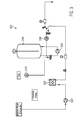
- FIG. 1 shows a first embodiment 100 of the device according to the invention.
- the apparatus 100 for mixing a pulp-containing fluid in this case comprises a line 121 for supplying water. This water is then mixed from a line 111 containing fruit pulp syrup. This syrup is conveyed by means of a positive displacement pump 110, eg in the form of a screw pump. The mixed fruit juice beverage is then continued via the line section 131, for example to a bottling plant.
- FIG. 2 shows a second embodiment 200 of the device according to the invention.
- the display mixer 200 shown therein has, in addition to the in FIG. 1 Components shown a pump 220 for the (preferably degassed) water, wherein the pump 220 is designed here as a centrifugal pump 220. Furthermore, a second positive displacement pump 230 is provided for advancing the mixed fluid. Between the pumps 210 and 230, the fluid is supplied via a line 241 CO 2 , that carried out a carbonization. A pressure is built up between the two pumps 210 and 230 (and also via the pump 220) by driving the first pump 210 on thrust action and the second pump 230 on braking action. In this way, the fluid can absorb the carbon dioxide.
- FIG. 3 shows a third embodiment 300 of the device according to the invention.
- a mixing tank 340 is provided.
- Another pump 350 provides for circulation of the mixed pulp or fibrous fluid, which pump is also referred to as Centrifugal pump can be performed, since it is operated at low speeds, and so a fiber-destructive effect is not or only slightly present.
- a cooling device 360 is provided for cooling the supplied degassed water.
- Various valves not described in detail here represent the connection of individual pipes.
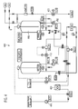
- FIG. 4 shows a fourth embodiment 400 of the device according to the invention. Compared to the embodiment according to FIG. 3 Here are further components provided.
- Centrifugal pumps are used according to the invention only where it applies to only circulate under construction of lowest pressures. As a result, they can run very slowly and therefore do not damage the product.
- the device according to the invention makes it possible to ensure inlet, outlet and circulation with only two openings at the bottom of the container, wherein the circulation is an important functional component and replaces the stirrers otherwise used. This prevents settling of the pulp and enables the stirring function even at such low fill levels that operation of an agitator is not yet permitted.
- the arrangement of the cooler in the water branch relocates the cooling task to a point where pulp and fibers are absent, thereby avoiding the use of expensive tube apparatus which would be necessary in the mixing zone.
- the enlarged syrup supply container can take up the complete contents of the syrup line.
- the attached circulation device also always holds solid components in suspension and homogenizes the contents of the container so that fluctuations in the syrup are brought to a gradient that can be compensated by the metering device.
- the size of the container makes it possible to absorb the mixing zones of syrup with water plus a certain amount of pure water and offers the possibility of greasing the contents of the tank in the direction of the original syrup (starting production) or diluting it down to beverage strength ( end of production).
- the contents of the container are each 100% usable, there are no Ver Dahlsmengen.
- the selection of the measuring instruments for the brix value ensures that even a light syrup or product can be measured so accurately that the obtained measured values allow a control of the mixing ratio.
- the arrangement of the piping and the pumps on the containers is designed so that the discharge pump sits at the lowest point and all other parts of this assembly can run empty. This ensures that the module can be emptied practically free of residue (except for adhesion).
- the arrangement of the dosing for liquid and gaseous components ensures that any of the components involved can be replenished at any time. This decisively increases production reliability.
- the container can be filled with mixture, the remaining small gas space can be purged air-free with minimal use of C02 or another span gas.
- the impregnation can be carried out with gas from the headspace, whereby the breathing of the container and thus a CO 2 loss can be largely reduced in underperformance mode.
- 3. By circulating the product is strongly mixed, control operations are smoothed and in Nachdosiervor réellen the container contents is then homogenized. When the system is at a standstill, the contents of the container can be stirred up at intervals.
- the containers involved can be depressurized, but foreclosure against the ingress of outside air is necessary.
- the circulation pump of the product container can be designed as a centrifugal pump to allow the said effects 1 and 3 from the above list.
- rework ie mixed phases arising during operation, can be easily processed with unknown, even fluctuating properties. It eliminates the need to homogenize the rework on this page.
- the arrangement shown also controls the operation of processing rework of unknown strength with water and / or syrup (or greasy finished product).
Landscapes
- Chemical & Material Sciences (AREA)
- Chemical Kinetics & Catalysis (AREA)
- Health & Medical Sciences (AREA)
- Nutrition Science (AREA)
- Life Sciences & Earth Sciences (AREA)
- Engineering & Computer Science (AREA)
- Food Science & Technology (AREA)
- Polymers & Plastics (AREA)
- Devices For Dispensing Beverages (AREA)
- Paper (AREA)
- Accessories For Mixers (AREA)
Abstract
Description
- Die vorliegende Erfindung betrifft eine Vorrichtung und ein Verfahren zum Mischen eines pulpe- und/oder faserhaltigen Fluids.
- Getränkemixer sind in der Mehrheit als 2-Komponentenmixer ausgeführt, wobei ein zuvor bereiteter Fertigsirup mit entgastem Wasser gemischt und das entstehende Gemisch bei Bedarf zusätzlich gekühlt und beispielsweise mit CO2, N2O, N2, O2 versetzt wird. Das fertige Getränk wird einer Füllmaschine bzw. Erhitzeranlage zugeführt.
- Die beschriebenen Maschinen werden nach dem Stand der Technik unter Verwendung von Kreiselpumpen, Regel- und Absperrventilen sowie Plattenwärmetauschern ausgeführt. Diese Bauteile stehen einer Verarbeitung von Getränken mit Feststoffanteil im Wege, da sie die festen Bestandteile wie beispielsweise Fruchtfleischstücke entweder nicht tolerieren (aufgrund geringer Spaltweiten) oder sogar zerstörend auf diese festen Bestandteile, insbesondere Fasern wirken. Die genannten Förder- und Regelorgane sind immer dann notwendig, wenn in hydraulisch gekoppelten Systemen eine Förderaufgabe mit zusätzlicher Druckerhöhung zu lösen ist, beispielsweise um ein Gas in das Getränk einzubringen.
- Weiterhin ist speziell im Bereich der feststoffhaltigen Produkte zu beobachten, dass tendenziell höherpreisige Produkte mit eher kleineren Chargen produziert werden. Dadurch ergeben sich häufige Produktwechsel mit den entsprechenden Verlusten durch Mischungszonen. Die ausgeführten Behältervolumina reichen in der Regel nicht aus, um z.B. den Inhalt einer kompletten Sirupleitung in einem Zuge vorzuschieben oder auszuschieben. Dies ist jedoch hinsichtlich einer minimal gehaltenen Vermischungszone wünschenswert, es hilft, die Unzulänglichkeiten der bauseitigen Installation auszugleichen, vermeidet Stillstände bei kurzzeitigem Ausfall der Sirupzufuhr und vermeidet eine Verfälschung der Dosierung bei schwankenden Zulaufverhältnissen. Weiterhin bieten die genannten Maschinen keinen Mechanismus, der sicherstellt, dass der Sirup-Inhalt der Sirupzuleitung wirklich zu 100% ausgenutzt werden kann. Hierzu wäre es nötig, die komplette Mischungszone von Wasser auf Sirup und zurück plus eine bestimmte Wassermenge zusätzlich als "Sirup" zu akzeptieren.
- Bei heute gebauten Anlagen wird außerdem immer öfter verlangt, dass die Vermischungsmengen von Produktausschüben nachgelagerter Anlagenteile nicht zu verwerfen sind, sondern dem Produktentstehungszweig an geeigneter Stelle wieder beizugeben sind. Auch diese Arbeitsweise wird von den heute gängigen Mixern nicht beherrscht, ist aber speziell bei feststoffhaltigen Produkten immer erwünscht.
- Ein weiterer Betreiberwunsch geht dahin, den CO2 Verbrauch der Karbonisiereinrichtung möglichst zu minimieren, insbesondere bei diskontinuierlicher Betriebsweise oder der Verarbeitung von Gebinden, welche zu einer Produktabnahme führen, die unterhalb des Regelbereichs des Mixers liegt. Dieser Anspruch kollidiert in den gängigen Maschinen regelmäßig mit der Eigenschaft, den Produktbehälter als Leerpuffer zu betreiben zusammen mit der Eigenschaft der Frischgaszugabe beim Imprägniergas.
- Angesichts dieser Nachteile des Stands der Technik ist es eine Aufgabe der vorliegenden Erfindung, eine Vorrichtung und ein Verfahren zum Mischen eines pulpe- und/oder faserhaltigen Fluids zur Verfügung zu stellen, die produktschonend und effizient sind.
- Die oben genannte Aufgabe wird gelöst durch eine Vorrichtung zum Mischen eines pulpe- und/oder faserhaltigen Fluids, welche Mittel zum scherfreien Bewegen des Fluids umfasst. Eine Beeinträchtigung der Pulpe- und/oder Faserdimensionen durch sich gegeneinander bewegende Kanten der herkömmlichen Mittel zum Bewegen des pulpe- und/oder faserhaltigen Fluids wird auf diese Weise vermieden.
- Gemäß einer Weiterbildung der erfindungsgemäßen Vorrichtung können die Mittel zum scherfreien Bewegen des Fluids eine erste Verdrängerpumpe, insbesondere eine erste Kolben- oder Schraubspindelpumpe umfassen. Somit kann beispielsweise auf üblicherweise eingesetzte Kreiselpumpen verzichtet werden, die Scherstellen aufweisen und Fasern durchtrennen können. Eine Verdrängerpumpe ist dagegen frei von derartigen Scherstellen und kann beispielsweise als Kolbenpumpe oder als Schraubspindelpumpe ausgeführt sein.
- Nach einer anderen Weiterbildung können die Mittel zum scherfreien Bewegen des Fluids eine zweite Verdrängerpumpe, insbesondere eine zweite Kolben- oder Schraubspindelpumpe, umfassen; wobei die erste oder die zweite Verdrängerpumpe als Schubpumpe und die zweite bzw. die erste Verdrängerpumpe als Bremspumpe betreibbar ist, wodurch im Betrieb der Vorrichtung eine Druckerhöhung des Fluids zwischen beiden Verdrängerpumpen erzielbar ist. Somit lässt sich pulpe- bzw. faserschonend ein Druckerhöhung erzielen (z.B. zur Karbonisierung) ohne Kreiselpumpen zu verwenden, die in diesem Fall mit hohen Drehzahlen betrieben werden müssten, was sich schädigend auf das Produkt, nämlich das pulpe- und/oder faserhaltigen Fluid, auswirkt.
- Eine Weiterbildung besteht darin, dass Mittel zum Einbringen eines Gases in das im Betrieb der Vorrichtung zwischen der ersten und der zweiten Verdrängerpumpe befindliche Fluid, insbesondere Mittel zum Karbonisieren des Fluids, vorgesehen sein können. Auf diese Weise kann ein Gas, wie etwa CO2 in das Fluid eingebracht werden. Dieses Mittel umfasst in der Regel eine Dosierleitung. Wenn mehrere Gase zugeführt werden sollen sind entsprechend mehrere Dosierleitungen vorgesehen.
- Erfindungsgemäß können die Mittel zum scherfreien Bewegen des Fluids regelventilfrei sein. Durch den Verzicht auf Regelventile können weitere pulpe- oder faserschädigende Wirkungen, die auf geringen Spaltweiten beruhen, vermieden werden. Gemäß einer anderen Weiterbildung kann die Vorrichtung dazu ausgebildet sein, das pulpe- und/oder faserhaltige Fluid zumindest aus Wasser, insbesondere entgastem Wasser, und ein oder mehreren pulpe- und/oder faserhaltigen Komponenten zu Mischen.
- In einer anderen Weiterbildung kann die Vorrichtung weiterhin einen Mischungsbehälter zum Aufnehmen wenigstens eines Teils des pulpe- und/oder faserhaltigen Fluids umfassen, wobei der Mischungsbehälter einen Zulauf und einen Ablauf aufweist über die im Betrieb der Vorrichtung eine Zirkulation des Fluids erfolgt, insbesondere wobei der Ablauf über eine Rückleitung mit einer Umwälzpumpe mit dem Zulauf verbunden ist. Hierdurch wird ein Absetzen der Pulpe verhindert und die Rührfunktion bereits bei geringen Füllständen ermöglicht. Die angebaute Umwälzeinrichtung hält auch feste Bestandteile immer in der Schwebe und homogenisiert den Inhalt des Behälters.
- Die Vorrichtung kann zudem Mittel zum Zuführen von Wasser als eine Eingangskomponente des Fluids und Mittel zum Kühlen des Wassers aufweisen. Die Anordnung des Kühlers im Wasserzweig verlegt die Kühlungsaufgabe an einen Punkt, wo keine Pulpe und Fasern vorkommen. Dadurch wird die Verwendung von teuren Röhrenapparaten vermieden, die im Gemischbereich nach dem Stand der Technik notwendig wären.
- Gemäß einer Weiterbildung kann weiterhin wenigstens einen Vorlaufbehälter zum Aufnehmen einer pulpe- und/oder faserhaltigen Eingangskomponente des Fluids vorgesehen sein, wobei der Vorlaufbehälter so bemessen sein kann, dass der vollständige Inhalt einer Dosierleitung für die pulpe- und/oder faserhaltige Eingangskomponente darin aufnehmbar ist, wobei die Dosierleitung zwischen dem Vorlaufbehälter und einem Eintrittspunkt an der Rückleitung vorgesehen ist, und wobei der Eintrittspunkt vorzugsweise ein Eintrittsventil ist. Somit kann beim An- und Abfahren der Anlage der Behälter aufgrund seiner Größe beispielsweise die Vermischungszonen von Sirup mit Wasser plus einer bestimmten Menge reinen Wassers aufnehmen. In beiden Fällen ist neben dem Inhalt der Dosierleitung (Sirupleitung) auch der Inhalt des Behälters nutzbar. In einer anderen Weiterbildung kann die Vorrichtung zudem eine Austragspumpe umfassen, die in einer solchen Höhe angeordnet ist, dass im Betrieb der Vorrichtung andere fluidführende Bestandteile der Vorrichtung zur Austragspumpe hin leerlaufen können. Dadurch wird sichergestellt, dass die Vorrichtung im Wesentlichen restfrei geleert werden kann.
- Die oben genannte Aufgabe wird weiterhin gelöst durch ein Verfahren zum Mischen eines pulpe- und/oder faserhaltigen Fluids, insbesondere eines pulpe- und/oder faserhaltigen Getränks, welches den Schritt umfasst: Scherfreies Bewegen des Fluids. Die bereits bei der erfindungsgemäßen Vorrichtung genannten Vorteile gelten hier entsprechend.
- Das erfindungsgemäße Verfahren kann in Entsprechung zu den Weiterbildungen der Vorrichtung ausgeführt werden.
- Weitere Merkmale und beispielhafte Ausführungsformen sowie Vorteile der vorliegenden Erfindung werden nachfolgend anhand der Zeichnungen näher erläutert. Es versteht sich, dass die Ausführungsformen nicht den Bereich der vorliegenden Erfindung erschöpfen. Es versteht sich weiterhin, dass einige oder sämtliche der im Weiteren beschriebenen Merkmale auch auf andere Weise miteinander kombiniert werden können.
-
- Figur 1
- stellt eine erste Ausführungsform der erfindungsgemäßen Vorrichtung dar.
- Figur 2
- stellt eine zweite Ausführungsform der erfindungsgemäßen Vorrichtung dar.
- Figur 3
- stellt eine dritte Ausführungsform der erfindungsgemäßen Vorrichtung dar.
- Figur 4
- stellt eine vierte Ausführungsform der erfindungsgemäßen Vorrichtung dar.
-
Figur 1 zeigt eine erste Ausführungsform 100 der erfindungsgemäßen Vorrichtung. Die Vorrichtung 100 zum Mischen eines pulpe- bzw. faserhaltigen Fluids umfasst in diesem Fall eine Leitung 121 zur Wasserzufuhr. Diesem Wasser wird dann aus einer Leitung 111 Fruchtfleisch enthaltender Sirup beigemischt. Dieser Sirup wird mittels einer Verdrängerpumpe 110, z.B. in Form einer Schraubenspindelpumpe, befördert. Das gemischte Fruchtsaftgetränk wird dann über den Leitungsabschnitt 131 weitergeführt, beispielsweise zu einer Abfüllanlage. -
Figur 2 zeigt eine zweite Ausführungsform 200 der erfindungsgemäßen Vorrichtung. De darin dargestellte Gertränkemixer 200 weist neben den inFigur 1 gezeigten Komponenten eine Pumpe 220 für das (vorzugsweise entgaste) Wasser auf, wobei die Pumpe 220 hier als Kreiselpumpe 220 ausgeführt ist. Weiterhin ist eine zweite Verdrängerpumpe 230 zum Weiterbefördern des gemischten Fluids vorgesehen. Zwischne den Pumpen 210 und 230 wird dem Fluid über eine Leitung 241 CO2 zugeführt, also eine Karbonisierung durchgeführt. Es wird zwischen den beiden Pumpen 210 und 230 (und auch über die Pumpe 220) ein Druck aufgebaut, indem die erste Pumpe 210 auf Schubwirkung und die zweite Pumpe 230 auf Bremswirkung gefahren werden. Auf diese Weise kann das Fluid das Kohlendioxid aufnehmen. -
Figur 3 zeigt eine dritte Ausführungsform 300 der erfindungsgemäßen Vorrichtung. Gegenüber den Ausführungsformen gemäßFiguren 1 und 2 ist hier insbesondere ein Mischungsbehälter 340 vorgesehen. Eine weitere Pumpe 350 sorgt für eine Zirkulation des gemischten pulpe- oder faserhaltigen Fluids, wobei diese Pumpe auch als Kreiselpumpe ausgeführt sein kann, da diese mit niedrigen Drehzahlen betrieben wird, und so eine faserzerstörende Wirkung nicht oder nur unwesentlich vorhanden ist. Desweiteren ist eine Kühlvorrichtung 360 zum Kühlen des zugeführten entgasten Wassers vorgesehen. Verschiedene nicht näher beschriebene Ventile stellen hier die Verbindung von einzelnen Rohrleitungen dar. -
Figur 4 zeigt eine vierte Ausführungsform 400 der erfindungsgemäßen Vorrichtung. Gegenüber der Ausführungsform nachFigur 3 sind hier weitere Komponenten vorgesehen. - BITTE ZU
FIGUR 4 NOCH NÄHERE INFORMATIONEN ZU DEN EINZELNEN KOMPONENTEN (z.B. mit Bezugszeichen und einer Bezugszeichenliste). BESTEN DANK IM VORAUS. André Crusius. - Zusammenfassend ist festzuhalten, dass der Verzicht auf Regelventile zur Produktsteuerung sowie die Verwendung von Verdrängerpumpen an Stellen, wo eine Druckerhöhung nötig ist, eine Beeinträchtigung der Pulpe- und Faserdimensionen vermeidet.
- Kreiselpumpen werden erfindungsgemäß nur da eingesetzt, wo es gilt, unter Aufbau geringster Drücke lediglich umzuwälzen. Dadurch können diese sehr langsam laufen und schädigen das Produkt deshalb nicht.
- Die erfindungsgemäße Vorrichtung macht es möglich, mit nur zwei Öffnungen am Behälterboden Zulauf, Ablauf und Zirkulation zu gewährleisten, wobei die Zirkulation ein wichtiger Funktionsbaustein ist und die sonst verwendeten Rührwerke ersetzt. Hierdurch wird ein Absetzen der Pulpe verhindert und die Rührfunktion bereits bei so geringen Füllständen ermöglicht, dass ein Betrieb eines Rührwerks noch nicht gestattet ist.
- Die Anordnung des Kühlers im Wasserzweig verlegt die Kühlungsaufgabe an einen Punkt, wo keine Pulpe und Fasern vorkommen und vermeidet dadurch die Verwendung von teuren Röhrenapparaten, die im Gemischbereich notwendig wären.
- Die gezeigte Anordnung garantiert, dass keine der Verdrängerpumpen in irgendeiner Betriebsart hydraulisch "auf Block" fahren kann. Es steht immer ein entsprechender Windkessel zur Verfügung. Damit kann auch an solchen Stellen auf produktschädigende Kreiselpumpen verzichtet werden, wo sie ansonsten aufgrund hydraulischer Eigenschaften unverzichtbar wären.
- Der vergrößerte Sirupvorlaufbehälter kann den kompletten Inhalt der Sirupleitung aufnehmen. Die angebaute Umwälzeinrichtung hält auch feste Bestandteile immer in der Schwebe und homogenisiert den Inhalt des Behälters, so dass Schwankungen im Sirup auf einen Gradienten gebracht werden, der von der Dosiereinrichtung ausgeregelt werden kann.
- Beim An- und Abfahren der Anlage kann der Behälter aufgrund seiner Größe die Vermischungszonen von Sirup mit Wasser plus einer bestimmten Menge reinen Wassers aufnehmen und bietet die Möglichkeit, den Inhalt des Tanks in Richtung des Originalsirups anzufetten (Produktionsbeginn) oder auf Getränkestärke herunter zu verdünnen (Produktionsende). In beiden Fällen ist außer dem Inhalt der Sirupleitung auch der Inhalt des Behälters jeweils zu 100% nutzbar, es entstehen keinerlei Verwurfsmengen.
- Die Auswahl der Messgeräte für den Brixwert (Maß für die lösliche Trockensubstanz in der Flüssigkeit) stellt sicher, dass auch ein Light-Sirup bzw. -Produkt so exakt gemessen werden kann, dass mit den gewonnenen Messwerten eine Steuerung des Mischungsverhältnisses möglich ist.
- Die Anordnung der Verrohrung und der Pumpen an den Behältern ist so gestaltet, dass die Austragspumpe am tiefsten Punkt sitzt und alle anderen Teile dieser Baugruppe dahin leerlaufen können. Dadurch wird sichergestellt, dass die Baugruppe praktisch restfrei leergeschöpft werden kann (Haftmengen ausgenommen).
- Durch die Verwendung von Verdrängerpumpen im Sirupauslauf wird auch beim letzten Produktausschub die Vermischungszone minimiert. Wird die Mischung entsprechend gesteuert, so lässt sich sogar in diesem Anlagenteil eine komplette Sirupfreispülung erreichen, indem die Dosage kurz vor Ende des Schöpfvorgangs angefettet wird, um sofort danach mit zusätzlichem Wasser auszugleichen. Dies kann so erfolgen, dass die Sirupleitung bis hinter den Dosierpunkt völlig frei von Sirup wird.
- Durch die Anordnung der Dosierleitungen für flüssige und gasförmige Bestandteile ist sichergestellt, dass jederzeit irgendeine der beteiligten Komponenten nachdosiert werden kann. Dies erhöht die Produktionssicherheit entscheidend.
- Durch den gezeigten Anbau einer Imprägniervorrichtung werden 3 Effekte erzielt. 1. Der Behälter kann mit Gemisch befüllt werden, der verbleibende kleine Gasraum kann mit geringstem Einsatz an C02 oder einem anderen Spanngas luftfrei gespült werden. 2. Die Imprägnierung kann mit Gas aus dem Kopfraum erfolgen, wodurch im Minderleistungsbetrieb das Atmen des Behälters und damit ein C02-Verlust weitgehend reduziert werden kann. 3. Durch die Umwälzung wird das Produkt stark vermischt, Regelvorgänge werden geglättet und bei Nachdosiervorgängen wird der Behälterinhalt anschließend homogenisiert. Bei Anlagenstillstand kann der Inhalt des Behälters intervallweise aufgerührt werden.
- Bei Verarbeitung nur stiller Produkte können die beteiligten Behälter drucklos ausgeführt sein, eine Abschottung gegen das Eindringen von Außenluft ist jedoch notwendig. In diesem Fall kann die Umwälzpumpe des Produktbehälters als Kreiselpumpe ausgeführt sein, um die genannten Effekte 1 und 3 aus der obigen Aufzählung zu ermöglichen.
- Mit der in
Figur 4 gezeigten Anordnung kann Rework, also beim Betrieb anfallende Mischphasen, mit unbekannten, auch schwankenden Eigenschaften problemlos mitverarbeitet werden. Es entfällt auf dieser Seite die Notwendigkeit zur Homogenisierung des Reworkanteils. Die gezeigte Anordnung beherrscht außerdem die Arbeitsweise, Rework unbekannter Stärke mit Wasser und/oder Sirup (bzw. überfettetem Fertigprodukt) zu verarbeiten. - Durch die gezeigte Anordnung ist es schließlich möglich, die Zuleitungen für Sirup und Rework als Zufuhr für die CIP Flüssigkeit zu verwenden bzw. in einem eigenen CIP Kreislauf zu reinigen, wobei die benötigte Medientrennung gewährleistet ist.
- Eine weitere Eigenschaft ist in der Anordnung nicht gezeigt, nämlich das Verfahren, die Produktleitung streckenweise als Doppelrohr auszuführen, wodurch eine weitere Kühlung bzw. Kühlhaltung bei Stillstand gewährleistet werden kann.
Claims (11)
- Vorrichtung zum Mischen eines pulpe- und/oder faserhaltigen Fluids, umfassend:Mittel zum scherfreien Bewegen des Fluids.
- Vorrichtung nach Anspruch 1, wobei die Mittel zum scherfreien Bewegen des Fluids eine erste Verdrängerpumpe, insbesondere eine erste Kolben- oder Schraubspindelpumpe, umfassen.
- Vorrichtung nach Anspruch 2, wobei die Mittel zum scherfreien Bewegen des Fluids eine zweite Verdrängerpumpe, insbesondere eine zweite Kolben- oder Schraubspindelpumpe, umfassen; und wobei die erste oder die zweite Verdrängerpumpe als Schubpumpe und die zweite bzw. die erste Verdrängerpumpe als Bremspumpe betreibbar ist, wodurch im Betrieb der Vorrichtung eine Druckerhöhung des Fluids zwischen beiden Verdrängerpumpen erzielbar ist.
- Vorrichtung nach Anspruch 3, weiterhin umfassend:Mittel zum Einbringen eines Gases in das im Betrieb der Vorrichtung zwischen der ersten und der zweiten Verdrängerpumpe befindliche Fluid, insbesondere Mittel zum Karbonisieren des Fluids.
- Vorrichtung nach einem der Ansprüche 1 bis 4, wobei die Mittel zum scherfreien Bewegen des Fluids regelventilfrei sind.
- Vorrichtung nach einem der Ansprüche 1 bis 5, wobei die Vorrichtung dazu ausgebildet ist, das pulpe- und/oder faserhaltige Fluid zumindest aus Wasser und ein oder mehreren pulpe- und/oder faserhaltigen Komponenten zu Mischen.
- Vorrichtung nach einem der Ansprüche 1 bis 6, weiterhin einen Mischungsbehälter zum Aufnehmen wenigstens eines Teils des pulpe- und/oder faserhaltigen Fluids umfassend, wobei der Mischungsbehälter einen Zulauf und einen Ablauf aufweist über die im Betrieb der Vorrichtung eine Zirkulation des Fluids erfolgt, insbesondere wobei der Ablauf über eine Rückleitung mit einer Umwälzpumpe mit dem Zulauf verbunden ist.
- Vorrichtung nach einem der Ansprüche 1 bis 7, weiterhin Mittel zum Zuführen von Wasser als eine Eingangskomponente des Fluids und Mittel zum Kühlen des zugeführten Wassers umfassend.
- Vorrichtung nach einem der Ansprüche 1 bis 8, weiterhin wenigstens einen Vorlaufbehälter zum Aufnehmen einer pulpe- und/oder faserhaltigen Eingangskomponente des Fluids umfassend, insbesondere wobei in Kombination mit Anspruch 7 der Vorlaufbehälter so bemessen ist, dass der vollständige Inhalt einer Dosierleitung für die pulpe- und/oder faserhaltige Eingangskomponente darin aufnehmbar ist, wobei die Dosierleitung zwischen dem Vorlaufbehälter und einem Eintrittspunkt an der Rückleitung vorgesehen ist, und wobei der Eintrittspunkt vorzugsweise ein Eintrittsventil ist.
- Vorrichtung nach einem der Ansprüche 1 bis 9, weiterhin eine Austragspumpe umfassend, die in einer solchen Höhe angeordnet ist, dass im Betrieb der Vorrichtung andere fluidführende Bestandteile der Vorrichtung zur Austragspumpe hin leerlaufen können.
- Verfahren zum Mischen eines pulpe- und/oder faserhaltigen Fluids, insbesondere eines pulpe- und/oder faserhaltigen Getränks, den Schritt umfassend:Scherfreies Bewegen des Fluids.
Applications Claiming Priority (1)
| Application Number | Priority Date | Filing Date | Title |
|---|---|---|---|
| DE102011084720A DE102011084720A1 (de) | 2011-10-18 | 2011-10-18 | Mixer für Pulpe- und Faserhaltige Getränke |
Publications (3)
| Publication Number | Publication Date |
|---|---|
| EP2583748A2 true EP2583748A2 (de) | 2013-04-24 |
| EP2583748A3 EP2583748A3 (de) | 2013-07-03 |
| EP2583748B1 EP2583748B1 (de) | 2015-07-15 |
Family
ID=46940376
Family Applications (1)
| Application Number | Title | Priority Date | Filing Date |
|---|---|---|---|
| EP12185814.6A Active EP2583748B1 (de) | 2011-10-18 | 2012-09-25 | Verfahren zum Mischen von pulpe- und faserhaltige Getränke |
Country Status (5)
| Country | Link |
|---|---|
| US (1) | US20130094323A1 (de) |
| EP (1) | EP2583748B1 (de) |
| CN (1) | CN103055735B (de) |
| BR (1) | BR102012026624A2 (de) |
| DE (1) | DE102011084720A1 (de) |
Cited By (1)
| Publication number | Priority date | Publication date | Assignee | Title |
|---|---|---|---|---|
| EP4005969A1 (de) | 2020-11-27 | 2022-06-01 | Krones Ag | Vorrichtung und verfahren zum befüllen eines behälters mit einem füllprodukt |
Families Citing this family (1)
| Publication number | Priority date | Publication date | Assignee | Title |
|---|---|---|---|---|
| GB2543307B (en) * | 2015-10-14 | 2020-12-09 | Selentus Science Ltd | Haemostatic device |
Family Cites Families (22)
| Publication number | Priority date | Publication date | Assignee | Title |
|---|---|---|---|---|
| US1781435A (en) * | 1928-07-06 | 1930-11-11 | Joseph B Carper | Process for the production of paints |
| US2565374A (en) * | 1949-11-30 | 1951-08-21 | Standard Oil Dev Co | Compounding of reciprocating pumps |
| NL78571C (de) * | 1953-04-17 | 1900-01-01 | ||
| US3565404A (en) * | 1968-10-15 | 1971-02-23 | Pako Corp | Device for mixing fluids |
| GB2072027B (en) * | 1980-01-30 | 1983-04-07 | Water Res Centre | Transfer of oxygen into wastewater |
| US4882097A (en) | 1988-09-06 | 1989-11-21 | Abc/Sebrn Tech Corp. | Carbonation system |
| US5842600A (en) | 1996-07-11 | 1998-12-01 | Standex International Corporation | Tankless beverage water carbonation process and apparatus |
| CA2295856A1 (en) * | 1997-07-10 | 1999-01-21 | Amcor Packaging (Australia) Pty Ltd | Producing liquid products contained in cans, bottles and other suitable containers |
| DE19741289C1 (de) * | 1997-09-19 | 1999-03-25 | Zentis Gmbh & Co Franz | Verfahren und Vorrichtung zur Herstellung von Fruchtzubereitungen |
| TW410175B (en) | 1998-04-16 | 2000-11-01 | Lee Wang Ken | A liquid spraying system |
| SE518088C2 (sv) * | 2000-10-30 | 2002-08-27 | Tetra Laval Holdings & Finance | Metod och anordning för att blanda två faser av en livsmedelsprodukt |
| ITMI20010688A1 (it) | 2001-03-30 | 2002-09-30 | Kosmologik Ind S R L | Apparato e metodo per il trattamento e la distribuzione di bevande |
| US6981387B1 (en) * | 2002-11-22 | 2006-01-03 | Morgan Louis A | Apparatus for delivering carbonated liquid at a temperature near or below the freezing point of water |
| US20060288874A1 (en) | 2005-06-24 | 2006-12-28 | The Coca-Cola Compay | In-Line, Instantaneous Carbonation System |
| CN101077764A (zh) * | 2006-05-08 | 2007-11-28 | 桂格燕麦公司 | 具有调味剂注入的热灌装饮料生产 |
| US20070281059A1 (en) | 2006-06-02 | 2007-12-06 | Leon Curtis Smith | Carbonated beverage national school lunch meal |
| US20090074919A1 (en) | 2007-09-13 | 2009-03-19 | Leon Curtis Smith | American school lunch meals |
| DE102008027492A1 (de) * | 2008-06-10 | 2009-12-17 | Khs Ag | Pasteurisierungsanlage |
| NO329835B1 (no) * | 2008-06-20 | 2011-01-03 | Cubility As | Blandeapparat og framgangsmate ved bruk av samme |
| CN101813402B (zh) * | 2009-05-31 | 2012-05-23 | 邢玉明 | 一种采用组合泵技术实现跨季节蓄热、蓄冷的热力站 |
| DE102011007787A1 (de) * | 2011-04-20 | 2014-01-16 | Krones Aktiengesellschaft | Vorrichtung und Verfahren zum Behandeln eines flüssigen Lebensmittelproduktes |
| ITMI20110170U1 (it) * | 2011-05-18 | 2012-11-19 | Fluid O Tech Srl | Dispositivo di saturazione dell'acqua potabile con anidride carbonica |
-
2011
- 2011-10-18 DE DE102011084720A patent/DE102011084720A1/de not_active Withdrawn
-
2012
- 2012-09-25 EP EP12185814.6A patent/EP2583748B1/de active Active
- 2012-10-17 BR BR102012026624-5A patent/BR102012026624A2/pt not_active IP Right Cessation
- 2012-10-18 CN CN201210397849.8A patent/CN103055735B/zh not_active Expired - Fee Related
- 2012-10-18 US US13/654,494 patent/US20130094323A1/en not_active Abandoned
Non-Patent Citations (1)
| Title |
|---|
| None |
Cited By (2)
| Publication number | Priority date | Publication date | Assignee | Title |
|---|---|---|---|---|
| EP4005969A1 (de) | 2020-11-27 | 2022-06-01 | Krones Ag | Vorrichtung und verfahren zum befüllen eines behälters mit einem füllprodukt |
| DE102020131579A1 (de) | 2020-11-27 | 2022-06-02 | Krones Aktiengesellschaft | Vorrichtung und Verfahren zum Befüllen eines Behälters mit einem Füllprodukt |
Also Published As
| Publication number | Publication date |
|---|---|
| CN103055735A (zh) | 2013-04-24 |
| CN103055735B (zh) | 2015-05-27 |
| BR102012026624A2 (pt) | 2014-06-03 |
| EP2583748B1 (de) | 2015-07-15 |
| EP2583748A3 (de) | 2013-07-03 |
| US20130094323A1 (en) | 2013-04-18 |
| DE102011084720A1 (de) | 2013-04-18 |
Similar Documents
| Publication | Publication Date | Title |
|---|---|---|
| EP2262582B1 (de) | Rührkesselreaktor sowie verfahren zur durchführung einer polymerisationsreaktion unter verwendung eines solchen rührkesselreaktors | |
| DE2439909C3 (de) | Vorrichtung zum Mischen und Ausschenken eines Getränkes | |
| DE60304002T2 (de) | Automatisiertes System und Verfahren zum Herstellen von hochviskosen Flüssigkeitsrezepturen | |
| WO2005077507A1 (de) | Verfahren und vorrichtung zur begasung von wasser | |
| EP3433204B1 (de) | Behälterfüllanordnung und -verfahren | |
| DE1962343A1 (de) | Verfahren und Vorrichtung zum Herstellen und Ausgeben eines halbgefrorenen kohlensaeurehaltigen Getraenkes | |
| EP1132337A1 (de) | Verfahren und Vorrichtung zum Mischen von Flüssigkeiten | |
| DE10320739B3 (de) | Vorrichtung zum Dispergieren und/oder Homogenisieren | |
| EP2388064B1 (de) | Vorrichtung und Verfahren zum Ausmischen von Getränken | |
| EP2623190A1 (de) | Karbonisiervorrichtung für Wein und weinhaltige Getränke | |
| WO1999048387A1 (de) | Anlage zur kontinuierlichen bereitstellung von mindestens zwei unterschiedlichen flüssigen lebensmittelgemischen | |
| EP3678981B1 (de) | Vorrichtung und verfahren zum befüllen eines behälters mit einem füllprodukt | |
| EP2583748B1 (de) | Verfahren zum Mischen von pulpe- und faserhaltige Getränke | |
| EP0512393A1 (de) | Verfahren und Vorrichtung zum Mischen von Getränkekomponenten | |
| EP3760577B1 (de) | Verfahren und vorrichtung zum befüllen eines behälters mit einem karbonisierten füllprodukt | |
| EP3678983A1 (de) | Vorrichtung zum befüllen eines behälters mit einem füllprodukt | |
| WO2010148521A1 (de) | Anlage und verfahren zur kontinuierlichen herstellung eines flüssigkeitsgemisches | |
| DE3340544A1 (de) | Einrichtung zum kontinuierlichen aufloesen von partikelartigen feststoffen in einer fluessigkeit | |
| EP0760254B1 (de) | Vorrichtung zum Homogenisieren fliessfähiger Stoffe | |
| EP2463739B1 (de) | Mixer für eine Getränkeabfüllanlage | |
| EP2272384A1 (de) | Verfahren und Vorrichtung zur Getränkeherstellung | |
| EP1920822B1 (de) | Vorrichtung und Verfahren zur kontinuierlichen Mischung und Entgasung von festen und/oder flüssigen Substanzen | |
| DE4315234C2 (de) | Verfahren und Vorrichtung zur Herstellung von Flüssigkeitsgemischen aus verschiedenen Einzelkomponenten | |
| DE102013212163B4 (de) | Vorrichtung zur Lagerung von zähflüssigen Medien | |
| EP2536487B1 (de) | Vorrichtung zum batchweisen ausmischen von zusatzkomponenten für mischprodukte |
Legal Events
| Date | Code | Title | Description |
|---|---|---|---|
| PUAI | Public reference made under article 153(3) epc to a published international application that has entered the european phase |
Free format text: ORIGINAL CODE: 0009012 |
|
| AK | Designated contracting states |
Kind code of ref document: A2 Designated state(s): AL AT BE BG CH CY CZ DE DK EE ES FI FR GB GR HR HU IE IS IT LI LT LU LV MC MK MT NL NO PL PT RO RS SE SI SK SM TR |
|
| AX | Request for extension of the european patent |
Extension state: BA ME |
|
| PUAL | Search report despatched |
Free format text: ORIGINAL CODE: 0009013 |
|
| AK | Designated contracting states |
Kind code of ref document: A3 Designated state(s): AL AT BE BG CH CY CZ DE DK EE ES FI FR GB GR HR HU IE IS IT LI LT LU LV MC MK MT NL NO PL PT RO RS SE SI SK SM TR |
|
| AX | Request for extension of the european patent |
Extension state: BA ME |
|
| RIC1 | Information provided on ipc code assigned before grant |
Ipc: B01F 3/04 20060101AFI20130529BHEP Ipc: B01F 3/08 20060101ALI20130529BHEP Ipc: A23L 2/54 20060101ALI20130529BHEP Ipc: B01F 15/02 20060101ALI20130529BHEP Ipc: A23L 2/02 20060101ALI20130529BHEP |
|
| 17P | Request for examination filed |
Effective date: 20131211 |
|
| RBV | Designated contracting states (corrected) |
Designated state(s): AL AT BE BG CH CY CZ DE DK EE ES FI FR GB GR HR HU IE IS IT LI LT LU LV MC MK MT NL NO PL PT RO RS SE SI SK SM TR |
|
| 17Q | First examination report despatched |
Effective date: 20140514 |
|
| GRAP | Despatch of communication of intention to grant a patent |
Free format text: ORIGINAL CODE: EPIDOSNIGR1 |
|
| RIC1 | Information provided on ipc code assigned before grant |
Ipc: B01F 3/08 20060101ALI20150216BHEP Ipc: B01F 3/04 20060101AFI20150216BHEP Ipc: A23L 2/02 20060101ALI20150216BHEP Ipc: A23L 2/54 20060101ALI20150216BHEP Ipc: B01F 15/02 20060101ALI20150216BHEP Ipc: A23L 2/70 20060101ALI20150216BHEP |
|
| INTG | Intention to grant announced |
Effective date: 20150318 |
|
| GRAS | Grant fee paid |
Free format text: ORIGINAL CODE: EPIDOSNIGR3 |
|
| GRAA | (expected) grant |
Free format text: ORIGINAL CODE: 0009210 |
|
| AK | Designated contracting states |
Kind code of ref document: B1 Designated state(s): AL AT BE BG CH CY CZ DE DK EE ES FI FR GB GR HR HU IE IS IT LI LT LU LV MC MK MT NL NO PL PT RO RS SE SI SK SM TR |
|
| REG | Reference to a national code |
Ref country code: CH Ref legal event code: NV Representative=s name: BOVARD AG, CH Ref country code: CH Ref legal event code: EP Ref country code: GB Ref legal event code: FG4D Free format text: NOT ENGLISH |
|
| REG | Reference to a national code |
Ref country code: FR Ref legal event code: PLFP Year of fee payment: 4 |
|
| REG | Reference to a national code |
Ref country code: IE Ref legal event code: FG4D Free format text: LANGUAGE OF EP DOCUMENT: GERMAN |
|
| REG | Reference to a national code |
Ref country code: AT Ref legal event code: REF Ref document number: 736488 Country of ref document: AT Kind code of ref document: T Effective date: 20150815 |
|
| REG | Reference to a national code |
Ref country code: DE Ref legal event code: R096 Ref document number: 502012003788 Country of ref document: DE |
|
| REG | Reference to a national code |
Ref country code: SE Ref legal event code: TRGR |
|
| REG | Reference to a national code |
Ref country code: NL Ref legal event code: MP Effective date: 20150715 |
|
| REG | Reference to a national code |
Ref country code: LT Ref legal event code: MG4D |
|
| PG25 | Lapsed in a contracting state [announced via postgrant information from national office to epo] |
Ref country code: NO Free format text: LAPSE BECAUSE OF FAILURE TO SUBMIT A TRANSLATION OF THE DESCRIPTION OR TO PAY THE FEE WITHIN THE PRESCRIBED TIME-LIMIT Effective date: 20151015 Ref country code: LV Free format text: LAPSE BECAUSE OF FAILURE TO SUBMIT A TRANSLATION OF THE DESCRIPTION OR TO PAY THE FEE WITHIN THE PRESCRIBED TIME-LIMIT Effective date: 20150715 Ref country code: GR Free format text: LAPSE BECAUSE OF FAILURE TO SUBMIT A TRANSLATION OF THE DESCRIPTION OR TO PAY THE FEE WITHIN THE PRESCRIBED TIME-LIMIT Effective date: 20151016 Ref country code: LT Free format text: LAPSE BECAUSE OF FAILURE TO SUBMIT A TRANSLATION OF THE DESCRIPTION OR TO PAY THE FEE WITHIN THE PRESCRIBED TIME-LIMIT Effective date: 20150715 Ref country code: FI Free format text: LAPSE BECAUSE OF FAILURE TO SUBMIT A TRANSLATION OF THE DESCRIPTION OR TO PAY THE FEE WITHIN THE PRESCRIBED TIME-LIMIT Effective date: 20150715 |
|
| PG25 | Lapsed in a contracting state [announced via postgrant information from national office to epo] |
Ref country code: ES Free format text: LAPSE BECAUSE OF FAILURE TO SUBMIT A TRANSLATION OF THE DESCRIPTION OR TO PAY THE FEE WITHIN THE PRESCRIBED TIME-LIMIT Effective date: 20150715 Ref country code: PL Free format text: LAPSE BECAUSE OF FAILURE TO SUBMIT A TRANSLATION OF THE DESCRIPTION OR TO PAY THE FEE WITHIN THE PRESCRIBED TIME-LIMIT Effective date: 20150715 Ref country code: PT Free format text: LAPSE BECAUSE OF FAILURE TO SUBMIT A TRANSLATION OF THE DESCRIPTION OR TO PAY THE FEE WITHIN THE PRESCRIBED TIME-LIMIT Effective date: 20151116 Ref country code: RS Free format text: LAPSE BECAUSE OF FAILURE TO SUBMIT A TRANSLATION OF THE DESCRIPTION OR TO PAY THE FEE WITHIN THE PRESCRIBED TIME-LIMIT Effective date: 20150715 Ref country code: HR Free format text: LAPSE BECAUSE OF FAILURE TO SUBMIT A TRANSLATION OF THE DESCRIPTION OR TO PAY THE FEE WITHIN THE PRESCRIBED TIME-LIMIT Effective date: 20150715 |
|
| REG | Reference to a national code |
Ref country code: DE Ref legal event code: R026 Ref document number: 502012003788 Country of ref document: DE |
|
| PLBI | Opposition filed |
Free format text: ORIGINAL CODE: 0009260 |
|
| PG25 | Lapsed in a contracting state [announced via postgrant information from national office to epo] |
Ref country code: SK Free format text: LAPSE BECAUSE OF FAILURE TO SUBMIT A TRANSLATION OF THE DESCRIPTION OR TO PAY THE FEE WITHIN THE PRESCRIBED TIME-LIMIT Effective date: 20150715 Ref country code: EE Free format text: LAPSE BECAUSE OF FAILURE TO SUBMIT A TRANSLATION OF THE DESCRIPTION OR TO PAY THE FEE WITHIN THE PRESCRIBED TIME-LIMIT Effective date: 20150715 Ref country code: CZ Free format text: LAPSE BECAUSE OF FAILURE TO SUBMIT A TRANSLATION OF THE DESCRIPTION OR TO PAY THE FEE WITHIN THE PRESCRIBED TIME-LIMIT Effective date: 20150715 Ref country code: LU Free format text: LAPSE BECAUSE OF FAILURE TO SUBMIT A TRANSLATION OF THE DESCRIPTION OR TO PAY THE FEE WITHIN THE PRESCRIBED TIME-LIMIT Effective date: 20150925 Ref country code: DK Free format text: LAPSE BECAUSE OF FAILURE TO SUBMIT A TRANSLATION OF THE DESCRIPTION OR TO PAY THE FEE WITHIN THE PRESCRIBED TIME-LIMIT Effective date: 20150715 Ref country code: MC Free format text: LAPSE BECAUSE OF FAILURE TO SUBMIT A TRANSLATION OF THE DESCRIPTION OR TO PAY THE FEE WITHIN THE PRESCRIBED TIME-LIMIT Effective date: 20150715 |
|
| PLAX | Notice of opposition and request to file observation + time limit sent |
Free format text: ORIGINAL CODE: EPIDOSNOBS2 |
|
| 26 | Opposition filed |
Opponent name: TETRA LAVAL HOLDINGS & FINANCE SA Effective date: 20160415 |
|
| PLAF | Information modified related to communication of a notice of opposition and request to file observations + time limit |
Free format text: ORIGINAL CODE: EPIDOSCOBS2 |
|
| PG25 | Lapsed in a contracting state [announced via postgrant information from national office to epo] |
Ref country code: RO Free format text: LAPSE BECAUSE OF FAILURE TO SUBMIT A TRANSLATION OF THE DESCRIPTION OR TO PAY THE FEE WITHIN THE PRESCRIBED TIME-LIMIT Effective date: 20150715 |
|
| REG | Reference to a national code |
Ref country code: IE Ref legal event code: MM4A |
|
| PLBB | Reply of patent proprietor to notice(s) of opposition received |
Free format text: ORIGINAL CODE: EPIDOSNOBS3 |
|
| PG25 | Lapsed in a contracting state [announced via postgrant information from national office to epo] |
Ref country code: IE Free format text: LAPSE BECAUSE OF NON-PAYMENT OF DUE FEES Effective date: 20150925 |
|
| REG | Reference to a national code |
Ref country code: FR Ref legal event code: PLFP Year of fee payment: 5 |
|
| PG25 | Lapsed in a contracting state [announced via postgrant information from national office to epo] |
Ref country code: SI Free format text: LAPSE BECAUSE OF FAILURE TO SUBMIT A TRANSLATION OF THE DESCRIPTION OR TO PAY THE FEE WITHIN THE PRESCRIBED TIME-LIMIT Effective date: 20150715 |
|
| PG25 | Lapsed in a contracting state [announced via postgrant information from national office to epo] |
Ref country code: MT Free format text: LAPSE BECAUSE OF FAILURE TO SUBMIT A TRANSLATION OF THE DESCRIPTION OR TO PAY THE FEE WITHIN THE PRESCRIBED TIME-LIMIT Effective date: 20150715 |
|
| GBPC | Gb: european patent ceased through non-payment of renewal fee |
Effective date: 20160925 |
|
| PG25 | Lapsed in a contracting state [announced via postgrant information from national office to epo] |
Ref country code: BG Free format text: LAPSE BECAUSE OF FAILURE TO SUBMIT A TRANSLATION OF THE DESCRIPTION OR TO PAY THE FEE WITHIN THE PRESCRIBED TIME-LIMIT Effective date: 20150715 Ref country code: HU Free format text: LAPSE BECAUSE OF FAILURE TO SUBMIT A TRANSLATION OF THE DESCRIPTION OR TO PAY THE FEE WITHIN THE PRESCRIBED TIME-LIMIT; INVALID AB INITIO Effective date: 20120925 Ref country code: SM Free format text: LAPSE BECAUSE OF FAILURE TO SUBMIT A TRANSLATION OF THE DESCRIPTION OR TO PAY THE FEE WITHIN THE PRESCRIBED TIME-LIMIT Effective date: 20150715 |
|
| PG25 | Lapsed in a contracting state [announced via postgrant information from national office to epo] |
Ref country code: CY Free format text: LAPSE BECAUSE OF FAILURE TO SUBMIT A TRANSLATION OF THE DESCRIPTION OR TO PAY THE FEE WITHIN THE PRESCRIBED TIME-LIMIT Effective date: 20150715 Ref country code: IS Free format text: LAPSE BECAUSE OF NON-PAYMENT OF DUE FEES Effective date: 20150715 Ref country code: NL Free format text: LAPSE BECAUSE OF FAILURE TO SUBMIT A TRANSLATION OF THE DESCRIPTION OR TO PAY THE FEE WITHIN THE PRESCRIBED TIME-LIMIT Effective date: 20150715 |
|
| PG25 | Lapsed in a contracting state [announced via postgrant information from national office to epo] |
Ref country code: GB Free format text: LAPSE BECAUSE OF NON-PAYMENT OF DUE FEES Effective date: 20160925 Ref country code: BE Free format text: LAPSE BECAUSE OF NON-PAYMENT OF DUE FEES Effective date: 20150930 |
|
| REG | Reference to a national code |
Ref country code: FR Ref legal event code: PLFP Year of fee payment: 6 |
|
| PG25 | Lapsed in a contracting state [announced via postgrant information from national office to epo] |
Ref country code: TR Free format text: LAPSE BECAUSE OF FAILURE TO SUBMIT A TRANSLATION OF THE DESCRIPTION OR TO PAY THE FEE WITHIN THE PRESCRIBED TIME-LIMIT Effective date: 20150715 |
|
| PLCK | Communication despatched that opposition was rejected |
Free format text: ORIGINAL CODE: EPIDOSNREJ1 |
|
| STAA | Information on the status of an ep patent application or granted ep patent |
Free format text: STATUS: THE PATENT HAS BEEN GRANTED |
|
| REG | Reference to a national code |
Ref country code: DE Ref legal event code: R100 Ref document number: 502012003788 Country of ref document: DE |
|
| PLBN | Opposition rejected |
Free format text: ORIGINAL CODE: 0009273 |
|
| STAA | Information on the status of an ep patent application or granted ep patent |
Free format text: STATUS: OPPOSITION REJECTED |
|
| 27O | Opposition rejected |
Effective date: 20171228 |
|
| PG25 | Lapsed in a contracting state [announced via postgrant information from national office to epo] |
Ref country code: MK Free format text: LAPSE BECAUSE OF FAILURE TO SUBMIT A TRANSLATION OF THE DESCRIPTION OR TO PAY THE FEE WITHIN THE PRESCRIBED TIME-LIMIT Effective date: 20150715 |
|
| REG | Reference to a national code |
Ref country code: FR Ref legal event code: PLFP Year of fee payment: 7 |
|
| PG25 | Lapsed in a contracting state [announced via postgrant information from national office to epo] |
Ref country code: AL Free format text: LAPSE BECAUSE OF FAILURE TO SUBMIT A TRANSLATION OF THE DESCRIPTION OR TO PAY THE FEE WITHIN THE PRESCRIBED TIME-LIMIT Effective date: 20150715 |
|
| REG | Reference to a national code |
Ref country code: AT Ref legal event code: MM01 Ref document number: 736488 Country of ref document: AT Kind code of ref document: T Effective date: 20170925 |
|
| PG25 | Lapsed in a contracting state [announced via postgrant information from national office to epo] |
Ref country code: AT Free format text: LAPSE BECAUSE OF NON-PAYMENT OF DUE FEES Effective date: 20170925 |
|
| REG | Reference to a national code |
Ref country code: DE Ref legal event code: R079 Ref document number: 502012003788 Country of ref document: DE Free format text: PREVIOUS MAIN CLASS: B01F0003040000 Ipc: B01F0023200000 |
|
| PGFP | Annual fee paid to national office [announced via postgrant information from national office to epo] |
Ref country code: FR Payment date: 20220808 Year of fee payment: 11 |
|
| PGFP | Annual fee paid to national office [announced via postgrant information from national office to epo] |
Ref country code: CH Payment date: 20221001 Year of fee payment: 11 |
|
| PGFP | Annual fee paid to national office [announced via postgrant information from national office to epo] |
Ref country code: IT Payment date: 20230810 Year of fee payment: 12 |
|
| REG | Reference to a national code |
Ref country code: CH Ref legal event code: PL |
|
| PG25 | Lapsed in a contracting state [announced via postgrant information from national office to epo] |
Ref country code: CH Free format text: LAPSE BECAUSE OF NON-PAYMENT OF DUE FEES Effective date: 20230930 |
|
| PG25 | Lapsed in a contracting state [announced via postgrant information from national office to epo] |
Ref country code: FR Free format text: LAPSE BECAUSE OF NON-PAYMENT OF DUE FEES Effective date: 20230930 Ref country code: CH Free format text: LAPSE BECAUSE OF NON-PAYMENT OF DUE FEES Effective date: 20230930 |
|
| PG25 | Lapsed in a contracting state [announced via postgrant information from national office to epo] |
Ref country code: IT Free format text: LAPSE BECAUSE OF NON-PAYMENT OF DUE FEES Effective date: 20240925 |
|
| PGFP | Annual fee paid to national office [announced via postgrant information from national office to epo] |
Ref country code: DE Payment date: 20250730 Year of fee payment: 14 |
|
| PGFP | Annual fee paid to national office [announced via postgrant information from national office to epo] |
Ref country code: SE Payment date: 20250812 Year of fee payment: 14 |