EP2583656A2 - Gerät zur kontinuierlichen passiven Bewegungstherapie des Kniegelenks - Google Patents
Gerät zur kontinuierlichen passiven Bewegungstherapie des Kniegelenks Download PDFInfo
- Publication number
- EP2583656A2 EP2583656A2 EP12189285.5A EP12189285A EP2583656A2 EP 2583656 A2 EP2583656 A2 EP 2583656A2 EP 12189285 A EP12189285 A EP 12189285A EP 2583656 A2 EP2583656 A2 EP 2583656A2
- Authority
- EP
- European Patent Office
- Prior art keywords
- heel
- coupled
- motor
- case
- foot
- Prior art date
- Legal status (The legal status is an assumption and is not a legal conclusion. Google has not performed a legal analysis and makes no representation as to the accuracy of the status listed.)
- Withdrawn
Links
- 210000000629 knee joint Anatomy 0.000 title description 13
- 210000003127 knee Anatomy 0.000 claims abstract description 16
- 210000002414 leg Anatomy 0.000 claims abstract description 9
- 238000010586 diagram Methods 0.000 description 4
- 210000002683 foot Anatomy 0.000 description 3
- 210000003141 lower extremity Anatomy 0.000 description 3
- 238000000034 method Methods 0.000 description 3
- 230000008878 coupling Effects 0.000 description 2
- 238000010168 coupling process Methods 0.000 description 2
- 238000005859 coupling reaction Methods 0.000 description 2
- 230000000284 resting effect Effects 0.000 description 2
- 101100521345 Mus musculus Prop1 gene Proteins 0.000 description 1
- 206010062575 Muscle contracture Diseases 0.000 description 1
- 108700017836 Prophet of Pit-1 Proteins 0.000 description 1
- 238000005452 bending Methods 0.000 description 1
- 230000005540 biological transmission Effects 0.000 description 1
- 238000006243 chemical reaction Methods 0.000 description 1
- 208000006111 contracture Diseases 0.000 description 1
- 125000004122 cyclic group Chemical group 0.000 description 1
- 230000006378 damage Effects 0.000 description 1
- 230000001575 pathological effect Effects 0.000 description 1
- 230000001020 rhythmical effect Effects 0.000 description 1
- 238000001356 surgical procedure Methods 0.000 description 1
- 210000000457 tarsus Anatomy 0.000 description 1
Images


Classifications
-
- A—HUMAN NECESSITIES
- A61—MEDICAL OR VETERINARY SCIENCE; HYGIENE
- A61H—PHYSICAL THERAPY APPARATUS, e.g. DEVICES FOR LOCATING OR STIMULATING REFLEX POINTS IN THE BODY; ARTIFICIAL RESPIRATION; MASSAGE; BATHING DEVICES FOR SPECIAL THERAPEUTIC OR HYGIENIC PURPOSES OR SPECIFIC PARTS OF THE BODY
- A61H1/00—Apparatus for passive exercising; Vibrating apparatus; Chiropractic devices, e.g. body impacting devices, external devices for briefly extending or aligning unbroken bones
- A61H1/02—Stretching or bending or torsioning apparatus for exercising
- A61H1/0237—Stretching or bending or torsioning apparatus for exercising for the lower limbs
- A61H1/024—Knee
-
- A—HUMAN NECESSITIES
- A61—MEDICAL OR VETERINARY SCIENCE; HYGIENE
- A61H—PHYSICAL THERAPY APPARATUS, e.g. DEVICES FOR LOCATING OR STIMULATING REFLEX POINTS IN THE BODY; ARTIFICIAL RESPIRATION; MASSAGE; BATHING DEVICES FOR SPECIAL THERAPEUTIC OR HYGIENIC PURPOSES OR SPECIFIC PARTS OF THE BODY
- A61H1/00—Apparatus for passive exercising; Vibrating apparatus; Chiropractic devices, e.g. body impacting devices, external devices for briefly extending or aligning unbroken bones
- A61H1/02—Stretching or bending or torsioning apparatus for exercising
- A61H1/0237—Stretching or bending or torsioning apparatus for exercising for the lower limbs
- A61H1/0255—Both knee and hip of a patient, e.g. in supine or sitting position, the feet being moved together in a plane substantially parallel to the body-symmetrical plane
- A61H1/0259—Both knee and hip of a patient, e.g. in supine or sitting position, the feet being moved together in a plane substantially parallel to the body-symmetrical plane moved by translation
-
- A—HUMAN NECESSITIES
- A61—MEDICAL OR VETERINARY SCIENCE; HYGIENE
- A61H—PHYSICAL THERAPY APPARATUS, e.g. DEVICES FOR LOCATING OR STIMULATING REFLEX POINTS IN THE BODY; ARTIFICIAL RESPIRATION; MASSAGE; BATHING DEVICES FOR SPECIAL THERAPEUTIC OR HYGIENIC PURPOSES OR SPECIFIC PARTS OF THE BODY
- A61H2201/00—Characteristics of apparatus not provided for in the preceding codes
- A61H2201/14—Special force transmission means, i.e. between the driving means and the interface with the user
- A61H2201/1481—Special movement conversion means
- A61H2201/149—Special movement conversion means rotation-linear or vice versa
-
- A—HUMAN NECESSITIES
- A61—MEDICAL OR VETERINARY SCIENCE; HYGIENE
- A61H—PHYSICAL THERAPY APPARATUS, e.g. DEVICES FOR LOCATING OR STIMULATING REFLEX POINTS IN THE BODY; ARTIFICIAL RESPIRATION; MASSAGE; BATHING DEVICES FOR SPECIAL THERAPEUTIC OR HYGIENIC PURPOSES OR SPECIFIC PARTS OF THE BODY
- A61H2201/00—Characteristics of apparatus not provided for in the preceding codes
- A61H2201/16—Physical interface with patient
- A61H2201/1602—Physical interface with patient kind of interface, e.g. head rest, knee support or lumbar support
- A61H2201/164—Feet or leg, e.g. pedal
- A61H2201/1642—Holding means therefor
Definitions
- the present invention relates to a motion device that operates with a heel assist for exercising the knee joint by the passive extension of the knee, preferably for rehabilitation purposes.
- the solution comprises a framework, an adjustable seat, exercise pedals and reciprocating shuttles which are mounted on supporting tracks and can be used to perform various exercises.
- the patent specification US 7,695,416 also features a device and method for knee joint rehabilitation.
- the device generally includes a frame, a lever member pivotally coupled to the frame at a first location, and an actuator pivotally coupled to the frame at a second location.
- the frame supports the patient in a manner that allows motion of the patient's knee joint, and the lever member bears against a portion of the patient's body below the knee joint.
- the actuator is also pivotally coupled to the lever member.
- the recognition of the present invention lies in that the full extension of the knee joint is performed with the use of a relatively simple device which supports the lower limb at the heel, and it is the heel part that is rhythmically vibrated in a vertical direction, with said rhythmic vibration being transmitted to the knee.
- the device is used to create a cyclic motion, the frequency and amplitude of which are adjustable, not only supporting the heel, but also enabling to heel to be placed in any chosen angle in a way that the motion thus created is perpendicular to the transverse axis of the knee. Therefore in the present solution the exercising of the knee is performed by holding the tarsus and thus moving the knee, without supporting the knee or the lower leg.
- the invention relates to a knee rehabilitation device, comprising a foot assist that can be attached to the leg, and a motion device which moves the assist in a given direction.
- the essence of the invention lies in that the leg is supported in a heel case placed on the heel, where the case is coupled to an appropriate frame, and the device contains an actuator that moves the leg set in the heel case in a vertical direction with given amplitude, and the actuator is joined to the axis of a motor, which is coupled to a controlling unit.
- One of the preferred embodiments of the actuator coupled to the heel case further comprises a swivel arm coupled to the heel case, and a roller is coupled to said arm.
- the roller is placed on the lateral surface of a control cone, in a way that the roller can be moved with an amplitude-adjusting threaded arm.
- the control cone is placed on an eccentric axle in a way that it can revolve.
- the axle is equipped with bearings in two bases coupled to the device, where the threaded arm is routed in one of the bases, while the control cone is supported with a support bearing and a spring on the other base.
- a rope is attached to the heel case, which is preferably attached to a pivot placed on a disk preferably through a worm drive, where the disc is coupled to a motor through a power unit, and for the adjustment of the amplitude the pivot is designed in a way so that it can be adjusted radially along the disc.
- the angle of the foot and the length of the heel case are preferably adjustable at the junction of the heel case and the rope.
- the control unit attached to the motor preferably contains a manual actuating unit, an emergency switch and an automatic actuating unit, all of which are connected to the motor through a mode switch.
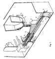
- the perspective view in Figure 1 is the section of a preferred embodiment of the invention.
- the device comprises a heel case 1, which is substantially made up of a basically U-shaped component and a sole prop which closes up the U-shaped component on one side.
- the sole prop 1 is coupled at a first location to a swivel arm 2 through a hole 3 to a component supporting and fixing the arm not included in the view and through a bar 4 coupled at a second location to a roller 5.
- the roller 5 of said heel case 1 thus equipped with a swivel arm 2 and a roller 5 is supported by the lateral surface of a control cone 6, said control cone 6 has an axle 7 placed parallel to the control cone, and the two ends of said axle 7 are equipped with bearings, resting on two bases 10 and 11.
- the two bases 10 and 11, as well as the component holding and the fixing the arm are attached to the enclosure of the device.
- a component adjusting the amplitude which is substantially a threaded bar 9, attached to the top of one of the bases 11.
- One end of the threaded bar 9 rests on the base of the control cone 6, while the other end, protruding from the enclosure of the device, enables the adjustment of the amplitude of the motion by moving the control cone 6 along the axle 7, and thus the heel case 1 gets into contact with the roller 5 located on the bar 4 of the heel case 1 on the sections with varying diameters of the control cone 6.
- the control cone 6 is supported by an appropriate bearing 12, which is supported by the second base 10 coupled to the enclosure of the device with a spring 13.
- the axle 7 of the control cone 6 is coupled to a motor 15 that ensures its rotation, and the axle 7 is equipped with a latching component 8.
- the motor 15 may be operated both in manual and automatic mode, and it is also equipped with an emergency switch 22.
- the block diagram of the control device coupled to the motor 15 is shown in Figure 4 , where the actuating component of the emergency switch 22, such as the push button, is accessible to the patient at all times, therefore the patient is able to switch off the device at any time.
- the actuating component of the emergency switch 22 such as the push button
- Figure 2 shows the elements of Figure 1 in a lateral section, illustrating how the control cone 6 can be moved back and forth along the axle 7 with the help of the amplitude adjusting threaded bar 9, and the amplitude of the vertical vibration of the heel case 1 in which the patient's heel rests can be set in the same way.
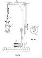
- Figures 3.a and 3.b show a further preferred embodiment of the invention in lateral view, where the lateral motion of the heel case 1 is due to a worm drive.
- the drive is developed in a way that the heel case 1 is coupled to a pivot 20 located on a disc 19 with a rope 18 routed over pulleys 17 through a heel case adjusting component 21, where said pivot 20 can be adjusted radially on the dial 19, and the dial 19 is coupled to the motor 15 with an appropriate transmission such as belt-transmission, and the motor 15 is connected to the control device 16.
- the amplitude of the motion of the heel depends on the radial position of the pivot 20 located on the disc 19, and the speed of the motion depends on the rotation speed of the motor 15.
- the frame 27, comprising the pulley 17 and the rope 18, the dial 19 and the whole motor structure, is a structure providing a base that is strong enough and relatively wide.
- the rehabilitation of the knee joint is achieved in a way that only the patient's heel is fixed, and the motion and extension of the knee joint is achieved through the vertical motion, i.e. vibration of the heel.
- FIG. 4 is the block diagram of the control device 16 of the motor 15.
- the control device 16 contains a manual actuating unit 23, an automatic actuating unit 24, a mode switch 25 and an emergency switch 22. If appropriate, a further sensor could be connected with series circuit to either the emergency switch 22 or the automatic actuating unit 24.
- the rotation speed of the motor 15 can be adjusted with an independently known rotation speed control governor, and the amplitude of the motion can be set manually while staying within the limits of vibration frequency and amplitude range.
- the output of the manual actuating unit 23 is connected to the mode switch 25, a further input of which is connected to the output of the automatic actuating unit 24, while a further entry of the mode switch is routed to the output of the emergency switch 22.
- the block diagram shows that the emergency switch 22 can be operated and switched into both modes, and it can switch off the device.
- the operation of the automatic actuating unit 24 can be achieved with computer or microcomputer control, in which case the required operations are performed by the operating software.
- the frequency can be pre-set according to a pre-set function or programme, or can be even adjusted during treatment.
- the amplitude can also be adjusted, but only manually.
- the connection between the device and the control device can be established with the help of Bluetooth, for example.
- the motor 15 can be operated essentially in three modes. One of them is operation mode is operation of the emergency switch 22, which is accessible to the patient at all times, with the help of which the patient can switch off the motor 15 at any time.
- the second mode is the manual mode, wherein the system can be operated manually in a way that it is turned on manually and the rotational speed is set manually.
- the third mode is the automatic mode.
- the vibration frequency can be set preferably up to 2 1/s in a stepwise or continuous mode, while the upper limit of the vibration amplitude is preferably 30 mm.
- the patient When the device is in operation, the patient lies on a bed, and places the heel in the heel case 1, where the heel is firmly fixed by a hook-and-loop fastener.
Landscapes
- Health & Medical Sciences (AREA)
- Epidemiology (AREA)
- Pain & Pain Management (AREA)
- Physical Education & Sports Medicine (AREA)
- Rehabilitation Therapy (AREA)
- Life Sciences & Earth Sciences (AREA)
- Animal Behavior & Ethology (AREA)
- General Health & Medical Sciences (AREA)
- Public Health (AREA)
- Veterinary Medicine (AREA)
- Rehabilitation Tools (AREA)
Applications Claiming Priority (1)
| Application Number | Priority Date | Filing Date | Title |
|---|---|---|---|
| HU1100585A HUP1100585A2 (en) | 2011-10-20 | 2011-10-20 | Exercise apparatus for rehabiliting knees by passive stretching |
Publications (2)
| Publication Number | Publication Date |
|---|---|
| EP2583656A2 true EP2583656A2 (de) | 2013-04-24 |
| EP2583656A3 EP2583656A3 (de) | 2013-05-29 |
Family
ID=89990482
Family Applications (1)
| Application Number | Title | Priority Date | Filing Date |
|---|---|---|---|
| EP12189285.5A Withdrawn EP2583656A3 (de) | 2011-10-20 | 2012-10-19 | Gerät zur kontinuierlichen passiven Bewegungstherapie des Kniegelenks |
Country Status (2)
| Country | Link |
|---|---|
| EP (1) | EP2583656A3 (de) |
| HU (1) | HUP1100585A2 (de) |
Cited By (3)
| Publication number | Priority date | Publication date | Assignee | Title |
|---|---|---|---|---|
| CN108433937A (zh) * | 2018-03-22 | 2018-08-24 | 中国人民解放军总医院 | 膝关节伸直辅助锻炼器 |
| CN109875848A (zh) * | 2019-04-03 | 2019-06-14 | 曲阜师范大学 | 一种卧式下肢康复机器人训练机构及系统 |
| CN111419642A (zh) * | 2020-04-29 | 2020-07-17 | 广州一康医疗设备实业有限公司 | 一种下肢康复训练用设备 |
Citations (3)
| Publication number | Priority date | Publication date | Assignee | Title |
|---|---|---|---|---|
| JPH08196585A (ja) | 1995-01-25 | 1996-08-06 | Yaskawa Electric Corp | 膝関節用連続他動運動装置 |
| US6010434A (en) | 1999-03-08 | 2000-01-04 | Hodges; Samuel G. | Knee rehabilitation exercise apparatus |
| US7695416B2 (en) | 2007-10-05 | 2010-04-13 | Jay John Weiner | Device and method for knee joint rehabilitation |
Family Cites Families (5)
| Publication number | Priority date | Publication date | Assignee | Title |
|---|---|---|---|---|
| FR1292358A (fr) * | 1961-03-23 | 1962-05-04 | Appareil pour le traitement thérapeutique des membres inférieurs et du bassin | |
| DE1566521B2 (de) * | 1967-04-29 | 1977-03-31 | Weiers, Hans, Dr.med., 7841 Steinenstadt | Vibrationsmassagegeraet |
| US5254060A (en) * | 1992-06-01 | 1993-10-19 | Bohanan Larry H | Motorized exerciser for human limbs |
| CN101854901B (zh) * | 2007-11-16 | 2013-03-20 | Mls兰尼有限公司 | 用于锻炼和/或分析使用者的运动系统的设备 |
| DE102008024918B4 (de) * | 2008-05-23 | 2013-09-05 | Claus Niemann-Bartels | Schlingentisch |
-
2011
- 2011-10-20 HU HU1100585A patent/HUP1100585A2/hu unknown
-
2012
- 2012-10-19 EP EP12189285.5A patent/EP2583656A3/de not_active Withdrawn
Patent Citations (3)
| Publication number | Priority date | Publication date | Assignee | Title |
|---|---|---|---|---|
| JPH08196585A (ja) | 1995-01-25 | 1996-08-06 | Yaskawa Electric Corp | 膝関節用連続他動運動装置 |
| US6010434A (en) | 1999-03-08 | 2000-01-04 | Hodges; Samuel G. | Knee rehabilitation exercise apparatus |
| US7695416B2 (en) | 2007-10-05 | 2010-04-13 | Jay John Weiner | Device and method for knee joint rehabilitation |
Cited By (5)
| Publication number | Priority date | Publication date | Assignee | Title |
|---|---|---|---|---|
| CN108433937A (zh) * | 2018-03-22 | 2018-08-24 | 中国人民解放军总医院 | 膝关节伸直辅助锻炼器 |
| CN108433937B (zh) * | 2018-03-22 | 2023-11-24 | 中国人民解放军总医院 | 膝关节伸直辅助锻炼器 |
| CN109875848A (zh) * | 2019-04-03 | 2019-06-14 | 曲阜师范大学 | 一种卧式下肢康复机器人训练机构及系统 |
| CN109875848B (zh) * | 2019-04-03 | 2020-12-29 | 曲阜师范大学 | 一种卧式下肢康复机器人训练机构及系统 |
| CN111419642A (zh) * | 2020-04-29 | 2020-07-17 | 广州一康医疗设备实业有限公司 | 一种下肢康复训练用设备 |
Also Published As
| Publication number | Publication date |
|---|---|
| EP2583656A3 (de) | 2013-05-29 |
| HUP1100585A2 (en) | 2013-05-28 |
Similar Documents
| Publication | Publication Date | Title |
|---|---|---|
| US6267735B1 (en) | Continuous passive motion device having a comfort zone feature | |
| KR101261650B1 (ko) | 운동 장치 | |
| KR101689079B1 (ko) | 손목 관절 재활훈련용 로봇 | |
| US6217532B1 (en) | Continuous passive motion device having a progressive range of motion | |
| US6221032B1 (en) | Continuous passive motion device having a rehabilitation enhancing mode of operation | |
| KR101492347B1 (ko) | 발목 관절 재활 운동 장치 | |
| US10780009B2 (en) | Apparatus for locomotion therapy | |
| CN209155002U (zh) | 锻炼设备 | |
| US11877972B2 (en) | Programmable multi-therapy inversion table | |
| JPWO2009084574A1 (ja) | 他動運動機器 | |
| EP2583656A2 (de) | Gerät zur kontinuierlichen passiven Bewegungstherapie des Kniegelenks | |
| KR101723893B1 (ko) | 손가락 운동장치 | |
| US6221033B1 (en) | Continuous passive motion device that accelerates through the non-working range of motion | |
| CN106473901A (zh) | 运动损伤康复辅助设备及控制方法 | |
| JP4548577B2 (ja) | 他動運動装置 | |
| JP2020110377A (ja) | 運動器具 | |
| CN210020208U (zh) | 踝泵运动仪及复健辅助设备 | |
| KR102157321B1 (ko) | 재활 운동이 가능한 휠체어용 발받침 | |
| JP5986239B2 (ja) | 膝関節刺激装置 | |
| JP2015134126A (ja) | マッサージ機 | |
| KR102774855B1 (ko) | 재활 운동 장치 | |
| KR20170079824A (ko) | 근육 강화용 수동 및 능동 구동장치 | |
| KR200323318Y1 (ko) | 다리 유산소 운동 기구 | |
| KR20140095198A (ko) | 손가락 재활기 | |
| CN210205738U (zh) | 康复用椭圆机及其步长调节机构 |
Legal Events
| Date | Code | Title | Description |
|---|---|---|---|
| PUAI | Public reference made under article 153(3) epc to a published international application that has entered the european phase |
Free format text: ORIGINAL CODE: 0009012 |
|
| AK | Designated contracting states |
Kind code of ref document: A2 Designated state(s): AL AT BE BG CH CY CZ DE DK EE ES FI FR GB GR HR HU IE IS IT LI LT LU LV MC MK MT NL NO PL PT RO RS SE SI SK SM TR |
|
| AX | Request for extension of the european patent |
Extension state: BA ME |
|
| PUAL | Search report despatched |
Free format text: ORIGINAL CODE: 0009013 |
|
| AK | Designated contracting states |
Kind code of ref document: A3 Designated state(s): AL AT BE BG CH CY CZ DE DK EE ES FI FR GB GR HR HU IE IS IT LI LT LU LV MC MK MT NL NO PL PT RO RS SE SI SK SM TR |
|
| AX | Request for extension of the european patent |
Extension state: BA ME |
|
| RIC1 | Information provided on ipc code assigned before grant |
Ipc: A61H 1/02 20060101AFI20130419BHEP |
|
| STAA | Information on the status of an ep patent application or granted ep patent |
Free format text: STATUS: THE APPLICATION IS DEEMED TO BE WITHDRAWN |
|
| 18D | Application deemed to be withdrawn |
Effective date: 20131130 |