EP2583594A1 - Appareil de cuisson avec un récipient de cuisson basculant autour d'un axe de basculement - Google Patents
Appareil de cuisson avec un récipient de cuisson basculant autour d'un axe de basculement Download PDFInfo
- Publication number
- EP2583594A1 EP2583594A1 EP12189083.4A EP12189083A EP2583594A1 EP 2583594 A1 EP2583594 A1 EP 2583594A1 EP 12189083 A EP12189083 A EP 12189083A EP 2583594 A1 EP2583594 A1 EP 2583594A1
- Authority
- EP
- European Patent Office
- Prior art keywords
- cooking
- spout
- upper edge
- wall
- front wall
- Prior art date
- Legal status (The legal status is an assumption and is not a legal conclusion. Google has not performed a legal analysis and makes no representation as to the accuracy of the status listed.)
- Granted
Links
Images


Classifications
-
- A—HUMAN NECESSITIES
- A47—FURNITURE; DOMESTIC ARTICLES OR APPLIANCES; COFFEE MILLS; SPICE MILLS; SUCTION CLEANERS IN GENERAL
- A47J—KITCHEN EQUIPMENT; COFFEE MILLS; SPICE MILLS; APPARATUS FOR MAKING BEVERAGES
- A47J27/00—Cooking-vessels
- A47J27/14—Cooking-vessels for use in hotels, restaurants, or canteens
-
- A—HUMAN NECESSITIES
- A47—FURNITURE; DOMESTIC ARTICLES OR APPLIANCES; COFFEE MILLS; SPICE MILLS; SUCTION CLEANERS IN GENERAL
- A47J—KITCHEN EQUIPMENT; COFFEE MILLS; SPICE MILLS; APPARATUS FOR MAKING BEVERAGES
- A47J37/00—Baking; Roasting; Grilling; Frying
- A47J37/12—Deep fat fryers, e.g. for frying fish or chips
- A47J37/1276—Constructional details
- A47J37/129—Frying vessels
Definitions
- the present invention relates to a cooking appliance for the treatment of food, with a cooking container, according to the preamble of claim 1.
- Garages for the treatment of food are known in many forms. They generally have a crucible-shaped cooking chamber which can be closed with a lid. To empty the cooking chamber of the cooking chamber enclosing cooking container is tilted, for example in the form of tilting frying pans.
- Such devices are used in particular for the preparation of food in the form of liquid, creamy or pourable foods, such as soups, sauces, scrambled eggs, goulash, desserts, rice or peas.
- This food is first prepared in the oven and there in particular heated.
- the cooking chamber is usually closed with a lid, which lies in particular sealing and pressure-resistant on the peripheral upper edge of the wall of the cooking container during the preparation process.
- the wall of the cooking chamber, so the cooking container itself is usually designed double-walled. This double-walledness improves the thermal insulation from the environment and also makes it possible to arrange certain aggregates, such as a heater, drains, etc. within the double wall.
- tiltable cooking vessels characterized in that the entire cooking container is tilted with the cooking chamber and its contents about a tilt axis, so that the prepared particular liquid food is poured over an edge of the wall, usually in one there possibly smaller receptacle.
- a spout is provided.
- a food cooking appliance comprising a cooking container having a front wall, a rear wall, two side walls and a bottom which together form a cooking space.
- a lid is provided which is capable of pressure-tightly close the cooking chamber, wherein the cooking container is tiltable about a tilt axis for emptying the cooking chamber.
- an upper edge of one of the walls is provided, in which a spout is formed, wherein the spout has a groove narrowing towards the upper edge, which has a slope towards the associated wall in the direction from the bottom to the edge.
- the concept according to DE 35 25 845 C2 uses for the arrangement of the channel, the double-walledness of the container and existing due to the double-walled width and the front wall by this front wall is slimmed to the upper edge in the region of the channel and thus forms the channel.
- the channel and the spout can be formed without interrupting the peripheral contact surface of the cooking container and lid, which would prevent a sealing effect.
- the present invention is therefore an object of the invention to provide a cooking appliance for the treatment of food, in which a useful Ausg screen is realized and at the same time a reliable seal is achieved with the lid closed.
- this object is achieved, in particular, in that at least one guide element, which projects beyond the associated wall, is arranged on the edge on both sides of the spout.
- the outflowing andmonschenden cooking product is directed according to the invention selectively in a desired flow direction.
- the design of the vanes remotely pronounced of "ears" on the two sides of the spout, allow for guiding and bundling the flow of food to be cooked, past and beyond the top of the associated wall of the cooking pan. A lateral spilling is thus avoided and the outflowing food can be poured out specifically and safely into the receptacle.
- the combination of the individual features results in a synergy effect.
- the medium to be poured is channeled in such a way that a beam-like behavior results.
- the food thus does not flow evenly over the entire available limit line of the cooking container, but jet-shaped between the guide elements in the desired direction. As a result, a targeted pouring the food into receptacles with relatively small openings is possible.
- a suitable dimensioning of the guide elements left and right of the spout allows a very accurate vorausberechenbaren cooking product over the entire tilt angle, each with a defined minimum height of Gargutstromes. This ensures safe pouring.
- a defined minimum height has the advantage that a clean and predictable separation of the material flowing over the edge of the wall can be ensured by this wall. Namely, if the flowing amount per unit time is too low, it tends to not flow directly on the wall over the edge, but to remain down through the adhesion forces on the wall and to form noses. Drop formation will also take place to a greater extent undesirable if the volume flow is too low. Thus, advantageously, these effects of the feature combination according to the invention can be avoided.
- the resulting cooking chamber is also easy to clean, since the area of the top edge has no additional inner edges, unlike the tried and tested Druckgarpfannen the applicant. Since there are only relatively thin sections in the area of the guide elements left and right next to the spout, namely in the form of the guide elements, preferably designed as baffles, the obstruction and the risk of burns of the user is significantly reduced because no unexpected hot surfaces exist more.
- the cooking chamber can be manufactured in one piece with a clearly defined upper edge.
- the production cost is further characterized in that only the guide elements or baffles must be added during the cooking process.
- the side surfaces of the spout form an angle of 130 ° to 140 °, preferably of 136 °, with the flat surface of the gutter of the spout.
- the resulting guide surfaces of the guide elements cause the guide elements themselves are not necessarily perpendicular to the top of the wall.
- the guide plates can therefore also be arranged at an angle to the wall plane.
- Such a design of the guide surfaces of the guide elements in a plane with the side surfaces of the gutter of the spout is of course additionally low in terms of production and also facilitates the cleaning of the entire area again.
- the guide elements are preferably baffles, which project in the particularly preferred embodiments triangular over the peripheral edge of the upper edges of the various walls (rear wall, side wall, front wall) upwards or projecting.
- the triangular surfaces are formed by the upper edge of the wall, the steeply rising side edge adjacent to the gutter of the spout and finally by the relatively gently sloping downwardly sloping upper boundary edge of the guide surface.
- the depth of the gutter of the spout is at least 50 mm at the edge.
- the inclination of the flat surface of the spout relative to the wall of the cooking container is between 10 ° and 15 °, preferably between 12 ° and 13 °.
- the upper edge is about 30% of the depth or "thickness" or thickness of the upper edge of the front wall outside the spout. This area is beyond the guide elements and therefore is available for the seal. He can therefore take over the task of sealing during the cooking process.
- corresponding recesses or recesses can be provided there in one embodiment, or a generally inverted tub-shaped lid is used. Other shapes of the lid are possible. It is important that remains during the cooking process by a sufficient support surface on the remaining upper edge of the front wall and circumferentially on the other wall elements.
- the guide elements can be produced without an additional pressing tool, which has the advantage that can be produced during the manufacturing process cooking tray, so in particular crucible, in different heights and sizes without corresponding costly conversion.
- the tilting process can be limited to a very short period of time and a large amount of food to be cooked very clean and targeted during this period.
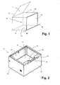
- FIG. 1 schematically is a perspective view of a basic shape of a tilting mirror or a tilting frying pan or other cooking appliance with a pivotable cooking chamber shown.
- the cooking container 10 has the shape of a pan, a crucible or a pan and has a bottom 11, a rear wall 12, two side walls 13 and 14 and a front wall 15. Upwards, the cooking container 10 is open and the side walls 13, 14, the front wall 15 and the rear wall 12 enclose a cooking chamber 16th
- the rear wall 12, the two side walls 13 and 14 and the front wall 15 are each double walls. Aggregates, thermal insulation and the like may be arranged between the inner wall facing the cooking chamber 16 and the outer wall facing the outer space.
- the cooking chamber 16 does not necessarily have cube or cuboid as in the FIG. 1 but can also be designed quite differently. It is also conceivable a step-shaped design of the walls, rounding or a dome shape of the bottom 11 are also conceivable.
- a cover 17 is provided, which is connected via a hinge axis 18 pivotally connected to the upper edge 30 of the rear wall 12.
- the lid 17 can cover the open top of the cooking container 10 during the cooking process and thus make the cooking chamber 16 to a fully enclosed interior, in which also an overpressure can be produced, if this is desired for the preparation of the food in the cooking chamber 16.
- the lid 17 rests on the upper edge of the rear wall 12, the two side walls 13 and 14 and the front wall 15 and is pressure-tightly sealed by suitable elements, not shown.
- the cooking container 10 can be tilted together with the food in it, preferably about an axis 20. Since the lid 17 as in the illustrated rough sketch about a hinge axis 18 is pivotable on the rear wall 12, the tilting axis 20 is expediently provided parallel to this hinge axis 18, in the region of the front wall 15, for example, and preferably in the region of the lower edge of the front wall 15, where it meets the floor 11.
- the upper edge 30 of the front wall 15 is the lowest level region of the peripheral edge of the cooking container 10, so that there (and only there) the contents of the cooking chamber 16 comes out.
- the entire contents of the cooking chamber 16 can be continuously poured out over this upper edge 30 of the front wall 15.
- this basic representation already shows an occurring problem: the pouring process would take place over the complete upper edge 30 and thus would not be able to take place into smaller containers which are located in front of the front wall 15. Moreover, even in the corner regions of the front wall 15 and the side walls 13 and 14, a subset of the outflowing food or cooking product would flow laterally beyond these edge regions of the upper edges of the side walls 13 and 14. It should be remembered that the amount of food leaking out has a finite height and is not zero. The outflowing stream may even have a height of 1 or more centimeters depending on the tilting speed.
- the wall of the cooking vessel 10, ie rear wall 12, side walls 13 and 14 and front wall 15, have a finite thickness, since they are double-walled.
- the upper edge or the peripheral edge, on which the cover 17, not shown, also rests circumferentially has a finite width and is formed mainly flat and at the same height.
- the pouring process during the tilting of the cooking vessel 10 would in turn take place via the front wall 15, in the FIG. 2 So right to the front.
- the upper edge 30 is formed in the central region of the front wall 15 clearly narrower or thinner than in the areas of the front wall 15 which are closer to the corners to the side walls 13 and 14.
- two guide elements 32 and 33 project upwards. These guide elements 32 and 33 are arranged to the left and right of the central region with the narrower upper edge 30. This central region is a spout 31, which is therefore bounded by the two guide elements 32 and 33 on the left and right.
- the guide elements 32 and 33 are inclined to the upper edge 30, in such a way that they exactly one boundary of the upper edge 30 to the narrowed central region of Upper edge 30 form in the region of the spout 31.
- the spout 31 thus runs obliquely in the pouring direction.
- the distance between the two guide elements 32 and 33 between the points at which they lie closest is at least 50 mm. Since here the spout 31 is limited in its width, he should not only have a certain minimum depth, but also a corresponding width to achieve a realistic and useful in practice volume flow. Of course, this width is also decisive for the selection of possibly small containers to be provided in front of the spout 31 for receiving the outflowing food.
- the guide elements have a height of less than 30 mm in the illustrated embodiment. This has the advantage that they can still be accommodated within the lid (not shown) 17 during the cooking process, but already have a height that already has a relevant positive effect on the volume flow.
- FIG. 3 is an enlarged view of a portion of the FIG. 2 given in a similar perspective view.
- FIG. 4 Now you can see the presentation from the FIG. 3 from a different point of view, namely from the cooking chamber 16 in the direction of the front wall 15. So you look from the inside of the cooking chamber 16 out or in other words from a position in front of the rear wall 12 on the spout 31, which is formed within the front wall 15. It can be seen that the spout 31 forms a groove 36 which has a flat surface. This groove 36 begins approximately at the transitional crease line between the bottom 11 and the front wall 15 and has an angle with the front wall 15, which is in the range between 10 ° and 15 °, preferably between 12 ° and 13 °. This means that from bottom to top, the flat surface of the channel 36 increases the cooking chamber diameter continuously, but very slowly.
- the drain 31 with its groove 36 is connected by two side surfaces 34 and 35 left and right with the unmodified areas of the wall of the front wall 15. These side surfaces are also inclined and in such a way that the width of the channel 36 of the drain 31 is reduced from bottom to top.
- side surfaces 34 and 35 protrude upward above the upper edge 30 of the front wall 15.
- the side surfaces 34 and 35 go here in guide surfaces, which are formed by the guide elements 32 and 33. In the illustrated preferred embodiment of the invention, therefore, the side surfaces 34 and 35 of the spout 31 and the respective associated guide surface of the guide elements 32 and 33 in a plane.
- the upper boundary lines of the guide elements 32 and 33 thus also form the upper limits of these side surfaces 34 and 35 or guide surfaces.
- FIG. 5 a Gar constitutioner 10 again shown with not shown cover 17.
- Gargut is indicated that should extend to a dashed level 51.
- the tilting axis 20 is perpendicular to the drawing sheet and the cooking tray 10 is tilted clockwise about the tilt axis 20 to the right. Accordingly, the level 51 of the example, liquid or creamy food remains horizontal.
- the difference h V is therefore the height of the food that leaves the cooking tray 10 as current during the tilting process at this moment and flows outward.
- the difference h V is at the same time the height difference between the highest point adjacent to the cooking space 16 or the line of the upper edge 30 on the one hand and the line of the upper edge 30 of the front wall 15 adjacent to the gutter of the spout 31, seen in FIG respectively current tilting state of the cooking vessel 10th
- the difference h V thus changes during the tilting process; it increases continuously during the pouring process.
- This also has the advantage that with decreasing Gargutinhalt in the cooking chamber 16, the possibility to drain the residual content is improved, so that in particular the food stream just before the final emptying not as usual in the art usually only cumbersome, as due to the low remained residual amount little "reprint" occurs.
- the function of the preferably triangular guide elements 32 and 33 is now clear. These ensure exactly the transition region between the undisturbed front wall 15 with the upper edge 30 in full width and the gutter of the spout 31 that in this area denser than in the undisturbed area of the Front wall 15 to the outer line of the upper edge 30 reaching parts of the food, however, there is no way outside of the intended spout 31 approximately laterally to reach the upper edge 30 and thus leave the front wall 15 in its unintended and unwanted area.
- the volume flow of the poured food is channeled and focused by the guide elements 32 and 33 in a stable and clean and accurate target beam.
- the formulation for the guide elements could also be chosen approximately as follows:
- the upper edge of the guide elements 32 and 33 forms extensions of the food product level at the beginning of the pouring process, with still the maximum volume of product to be cooked. Now begins the pouring process, so the spout and the guide elements 32 and 33 form a free space below the level height 51 of the food of at least the desired volume flow height in the center of the spout 31. This desired volume flow height is of the order of at least 10 mm.
- the guide elements prevent lateral flow of the cooking product flow.
- the distance between the side walls of the spout 31 and also the distance between the two baffles of the baffles 32 and 33 decreases whose width during the pouring operation is smaller than the width of the spout 31.
Landscapes
- Engineering & Computer Science (AREA)
- Food Science & Technology (AREA)
- Cookers (AREA)
Applications Claiming Priority (1)
| Application Number | Priority Date | Filing Date | Title |
|---|---|---|---|
| DE102011116273A DE102011116273B4 (de) | 2011-10-19 | 2011-10-19 | Gargerät mit einem um eine Kippachse kippbaren Garbehälter |
Publications (2)
| Publication Number | Publication Date |
|---|---|
| EP2583594A1 true EP2583594A1 (fr) | 2013-04-24 |
| EP2583594B1 EP2583594B1 (fr) | 2014-04-09 |
Family
ID=47115438
Family Applications (1)
| Application Number | Title | Priority Date | Filing Date |
|---|---|---|---|
| EP20120189083 Not-in-force EP2583594B1 (fr) | 2011-10-19 | 2012-10-18 | Appareil de cuisson avec un récipient de cuisson basculant autour d'un axe de basculement |
Country Status (2)
| Country | Link |
|---|---|
| EP (1) | EP2583594B1 (fr) |
| DE (1) | DE102011116273B4 (fr) |
Families Citing this family (2)
| Publication number | Priority date | Publication date | Assignee | Title |
|---|---|---|---|---|
| DE102019124153A1 (de) * | 2019-09-09 | 2021-03-11 | Rational Wittenheim Sas | Gargerätetiegel |
| EP3854273B1 (fr) | 2020-01-22 | 2023-07-05 | MKN Maschinenfabrik Kurt Neubauer GmbH & Co. KG | Appareil de cuisson pour cuisines d'établissements de restauration |
Citations (6)
| Publication number | Priority date | Publication date | Assignee | Title |
|---|---|---|---|---|
| DE6914432U (de) * | 1969-04-09 | 1969-10-02 | Senkingwerk | Kippbratpfanne, auf saeule und konsole gelagert |
| US3797377A (en) * | 1972-05-18 | 1974-03-19 | South Bend Range Corp | Tiltable cooking pan |
| US3964378A (en) * | 1974-03-22 | 1976-06-22 | The Frymaster Corporation | Tilting frypan with drain system |
| DE3525845A1 (de) | 1984-10-19 | 1986-04-24 | Robert Mauch Elro-Werke AG, Bremgarten | Kippbares gefaess mit einer wanne |
| EP1488721A1 (fr) * | 2003-06-18 | 2004-12-22 | Frima S.A. | Récipient en forme de cuve pour une friteuse et friteuse |
| JP2007285546A (ja) * | 2006-04-13 | 2007-11-01 | Nichiwa Denki Kk | 加熱調理機 |
Family Cites Families (1)
| Publication number | Priority date | Publication date | Assignee | Title |
|---|---|---|---|---|
| FR2070617A5 (fr) * | 1969-12-11 | 1971-09-10 | Gentilini Et Berthon |
-
2011
- 2011-10-19 DE DE102011116273A patent/DE102011116273B4/de not_active Expired - Fee Related
-
2012
- 2012-10-18 EP EP20120189083 patent/EP2583594B1/fr not_active Not-in-force
Patent Citations (6)
| Publication number | Priority date | Publication date | Assignee | Title |
|---|---|---|---|---|
| DE6914432U (de) * | 1969-04-09 | 1969-10-02 | Senkingwerk | Kippbratpfanne, auf saeule und konsole gelagert |
| US3797377A (en) * | 1972-05-18 | 1974-03-19 | South Bend Range Corp | Tiltable cooking pan |
| US3964378A (en) * | 1974-03-22 | 1976-06-22 | The Frymaster Corporation | Tilting frypan with drain system |
| DE3525845A1 (de) | 1984-10-19 | 1986-04-24 | Robert Mauch Elro-Werke AG, Bremgarten | Kippbares gefaess mit einer wanne |
| EP1488721A1 (fr) * | 2003-06-18 | 2004-12-22 | Frima S.A. | Récipient en forme de cuve pour une friteuse et friteuse |
| JP2007285546A (ja) * | 2006-04-13 | 2007-11-01 | Nichiwa Denki Kk | 加熱調理機 |
Also Published As
| Publication number | Publication date |
|---|---|
| EP2583594B1 (fr) | 2014-04-09 |
| DE102011116273A1 (de) | 2013-04-25 |
| DE102011116273B4 (de) | 2013-12-12 |
Similar Documents
| Publication | Publication Date | Title |
|---|---|---|
| EP2393401B1 (fr) | Fermeture pour un récipient à boisson | |
| EP0227977B1 (fr) | Machine à café | |
| EP2341803B1 (fr) | Préparateur de boisson pourvu d'une partie rapportée installée dans un récipient | |
| DE1127811T1 (de) | Behälter mit vermindertem Geräusch des Deckels während dessen Schliessbewegung | |
| EP1688076A1 (fr) | Récipient de cuisson | |
| DE3720149A1 (de) | Kaffeemaschine | |
| WO1990009133A1 (fr) | Recipient de cuisson | |
| EP2583594B1 (fr) | Appareil de cuisson avec un récipient de cuisson basculant autour d'un axe de basculement | |
| EP0220688B1 (fr) | Machine à café ou à thé | |
| DE7915161U1 (de) | Kaffee- und/oder Espressomaschine | |
| DE102011002821A1 (de) | Siebeinsatz | |
| EP0916900B1 (fr) | Moule de boulangerie | |
| EP3195767B1 (fr) | Automate de préparation de boissons comprenant une grille pour les tasses | |
| DE202004009759U1 (de) | Kaffeebereiter | |
| DE102006049893B3 (de) | Abstellvorrichtung an Getränkemaschinen | |
| DE19907072B4 (de) | Friteuse | |
| EP3854273B1 (fr) | Appareil de cuisson pour cuisines d'établissements de restauration | |
| DE102010046783B4 (de) | Gefäßdeckel für ein optimiertes Entleeren eines Gefäßes, insbesondere Kochtopfdeckel für einen Kochtopf | |
| DE202004006760U1 (de) | Behältnis zur Aufnahme eines oder mehrerer portionierter Lebensmittel | |
| EP0306679A2 (fr) | Récipient, en particulier récipient isolant | |
| DE4413282A1 (de) | Vorrichtung für einen Wasserkocher mit einer elektrischen Heizeinrichtung | |
| DE102012222029A1 (de) | Flüssigkeitsbehälter | |
| DE102012000901B4 (de) | Kochbehälter mit entfernbarem Sieb | |
| EP0053234A1 (fr) | Couvercle isolant pour un pot à café à isolation thermique | |
| EP3446602B1 (fr) | Réservoir d'eau résiduelle pour un dispositif de préparation de boissons ainsi que dispositif de préparation de boissons |
Legal Events
| Date | Code | Title | Description |
|---|---|---|---|
| PUAI | Public reference made under article 153(3) epc to a published international application that has entered the european phase |
Free format text: ORIGINAL CODE: 0009012 |
|
| AK | Designated contracting states |
Kind code of ref document: A1 Designated state(s): AL AT BE BG CH CY CZ DE DK EE ES FI FR GB GR HR HU IE IS IT LI LT LU LV MC MK MT NL NO PL PT RO RS SE SI SK SM TR |
|
| AX | Request for extension of the european patent |
Extension state: BA ME |
|
| RAP1 | Party data changed (applicant data changed or rights of an application transferred) |
Owner name: MKN MASCHINENFABRIK KURT NEUBAUER GMBH & CO. KG |
|
| 17P | Request for examination filed |
Effective date: 20131021 |
|
| RBV | Designated contracting states (corrected) |
Designated state(s): AL AT BE BG CH CY CZ DE DK EE ES FI FR GB GR HR HU IE IS IT LI LT LU LV MC MK MT NL NO PL PT RO RS SE SI SK SM TR |
|
| 17Q | First examination report despatched |
Effective date: 20131118 |
|
| GRAP | Despatch of communication of intention to grant a patent |
Free format text: ORIGINAL CODE: EPIDOSNIGR1 |
|
| INTG | Intention to grant announced |
Effective date: 20131220 |
|
| GRAS | Grant fee paid |
Free format text: ORIGINAL CODE: EPIDOSNIGR3 |
|
| GRAA | (expected) grant |
Free format text: ORIGINAL CODE: 0009210 |
|
| AK | Designated contracting states |
Kind code of ref document: B1 Designated state(s): AL AT BE BG CH CY CZ DE DK EE ES FI FR GB GR HR HU IE IS IT LI LT LU LV MC MK MT NL NO PL PT RO RS SE SI SK SM TR |
|
| REG | Reference to a national code |
Ref country code: GB Ref legal event code: FG4D Free format text: NOT ENGLISH |
|
| REG | Reference to a national code |
Ref country code: CH Ref legal event code: EP Ref country code: AT Ref legal event code: REF Ref document number: 660844 Country of ref document: AT Kind code of ref document: T Effective date: 20140415 |
|
| REG | Reference to a national code |
Ref country code: IE Ref legal event code: FG4D Free format text: LANGUAGE OF EP DOCUMENT: GERMAN |
|
| REG | Reference to a national code |
Ref country code: DE Ref legal event code: R096 Ref document number: 502012000573 Country of ref document: DE Effective date: 20140522 |
|
| REG | Reference to a national code |
Ref country code: NL Ref legal event code: VDEP Effective date: 20140409 |
|
| REG | Reference to a national code |
Ref country code: LT Ref legal event code: MG4D |
|
| PG25 | Lapsed in a contracting state [announced via postgrant information from national office to epo] |
Ref country code: LT Free format text: LAPSE BECAUSE OF FAILURE TO SUBMIT A TRANSLATION OF THE DESCRIPTION OR TO PAY THE FEE WITHIN THE PRESCRIBED TIME-LIMIT Effective date: 20140409 Ref country code: BG Free format text: LAPSE BECAUSE OF FAILURE TO SUBMIT A TRANSLATION OF THE DESCRIPTION OR TO PAY THE FEE WITHIN THE PRESCRIBED TIME-LIMIT Effective date: 20140709 Ref country code: NL Free format text: LAPSE BECAUSE OF FAILURE TO SUBMIT A TRANSLATION OF THE DESCRIPTION OR TO PAY THE FEE WITHIN THE PRESCRIBED TIME-LIMIT Effective date: 20140409 Ref country code: IS Free format text: LAPSE BECAUSE OF FAILURE TO SUBMIT A TRANSLATION OF THE DESCRIPTION OR TO PAY THE FEE WITHIN THE PRESCRIBED TIME-LIMIT Effective date: 20140809 Ref country code: NO Free format text: LAPSE BECAUSE OF FAILURE TO SUBMIT A TRANSLATION OF THE DESCRIPTION OR TO PAY THE FEE WITHIN THE PRESCRIBED TIME-LIMIT Effective date: 20140709 Ref country code: FI Free format text: LAPSE BECAUSE OF FAILURE TO SUBMIT A TRANSLATION OF THE DESCRIPTION OR TO PAY THE FEE WITHIN THE PRESCRIBED TIME-LIMIT Effective date: 20140409 Ref country code: GR Free format text: LAPSE BECAUSE OF FAILURE TO SUBMIT A TRANSLATION OF THE DESCRIPTION OR TO PAY THE FEE WITHIN THE PRESCRIBED TIME-LIMIT Effective date: 20140710 |
|
| PG25 | Lapsed in a contracting state [announced via postgrant information from national office to epo] |
Ref country code: PL Free format text: LAPSE BECAUSE OF FAILURE TO SUBMIT A TRANSLATION OF THE DESCRIPTION OR TO PAY THE FEE WITHIN THE PRESCRIBED TIME-LIMIT Effective date: 20140409 Ref country code: RS Free format text: LAPSE BECAUSE OF FAILURE TO SUBMIT A TRANSLATION OF THE DESCRIPTION OR TO PAY THE FEE WITHIN THE PRESCRIBED TIME-LIMIT Effective date: 20140409 Ref country code: LV Free format text: LAPSE BECAUSE OF FAILURE TO SUBMIT A TRANSLATION OF THE DESCRIPTION OR TO PAY THE FEE WITHIN THE PRESCRIBED TIME-LIMIT Effective date: 20140409 Ref country code: SE Free format text: LAPSE BECAUSE OF FAILURE TO SUBMIT A TRANSLATION OF THE DESCRIPTION OR TO PAY THE FEE WITHIN THE PRESCRIBED TIME-LIMIT Effective date: 20140409 Ref country code: ES Free format text: LAPSE BECAUSE OF FAILURE TO SUBMIT A TRANSLATION OF THE DESCRIPTION OR TO PAY THE FEE WITHIN THE PRESCRIBED TIME-LIMIT Effective date: 20140409 Ref country code: HR Free format text: LAPSE BECAUSE OF FAILURE TO SUBMIT A TRANSLATION OF THE DESCRIPTION OR TO PAY THE FEE WITHIN THE PRESCRIBED TIME-LIMIT Effective date: 20140409 |
|
| PG25 | Lapsed in a contracting state [announced via postgrant information from national office to epo] |
Ref country code: PT Free format text: LAPSE BECAUSE OF FAILURE TO SUBMIT A TRANSLATION OF THE DESCRIPTION OR TO PAY THE FEE WITHIN THE PRESCRIBED TIME-LIMIT Effective date: 20140811 |
|
| REG | Reference to a national code |
Ref country code: DE Ref legal event code: R097 Ref document number: 502012000573 Country of ref document: DE |
|
| PG25 | Lapsed in a contracting state [announced via postgrant information from national office to epo] |
Ref country code: EE Free format text: LAPSE BECAUSE OF FAILURE TO SUBMIT A TRANSLATION OF THE DESCRIPTION OR TO PAY THE FEE WITHIN THE PRESCRIBED TIME-LIMIT Effective date: 20140409 Ref country code: RO Free format text: LAPSE BECAUSE OF FAILURE TO SUBMIT A TRANSLATION OF THE DESCRIPTION OR TO PAY THE FEE WITHIN THE PRESCRIBED TIME-LIMIT Effective date: 20140409 Ref country code: SK Free format text: LAPSE BECAUSE OF FAILURE TO SUBMIT A TRANSLATION OF THE DESCRIPTION OR TO PAY THE FEE WITHIN THE PRESCRIBED TIME-LIMIT Effective date: 20140409 Ref country code: DK Free format text: LAPSE BECAUSE OF FAILURE TO SUBMIT A TRANSLATION OF THE DESCRIPTION OR TO PAY THE FEE WITHIN THE PRESCRIBED TIME-LIMIT Effective date: 20140409 |
|
| PLBE | No opposition filed within time limit |
Free format text: ORIGINAL CODE: 0009261 |
|
| STAA | Information on the status of an ep patent application or granted ep patent |
Free format text: STATUS: NO OPPOSITION FILED WITHIN TIME LIMIT |
|
| 26N | No opposition filed |
Effective date: 20150112 |
|
| REG | Reference to a national code |
Ref country code: DE Ref legal event code: R097 Ref document number: 502012000573 Country of ref document: DE Effective date: 20150112 |
|
| PG25 | Lapsed in a contracting state [announced via postgrant information from national office to epo] |
Ref country code: MC Free format text: LAPSE BECAUSE OF FAILURE TO SUBMIT A TRANSLATION OF THE DESCRIPTION OR TO PAY THE FEE WITHIN THE PRESCRIBED TIME-LIMIT Effective date: 20140409 Ref country code: LU Free format text: LAPSE BECAUSE OF FAILURE TO SUBMIT A TRANSLATION OF THE DESCRIPTION OR TO PAY THE FEE WITHIN THE PRESCRIBED TIME-LIMIT Effective date: 20141018 |
|
| PG25 | Lapsed in a contracting state [announced via postgrant information from national office to epo] |
Ref country code: BE Free format text: LAPSE BECAUSE OF NON-PAYMENT OF DUE FEES Effective date: 20141031 |
|
| REG | Reference to a national code |
Ref country code: IE Ref legal event code: MM4A |
|
| PG25 | Lapsed in a contracting state [announced via postgrant information from national office to epo] |
Ref country code: SI Free format text: LAPSE BECAUSE OF FAILURE TO SUBMIT A TRANSLATION OF THE DESCRIPTION OR TO PAY THE FEE WITHIN THE PRESCRIBED TIME-LIMIT Effective date: 20140409 |
|
| REG | Reference to a national code |
Ref country code: FR Ref legal event code: PLFP Year of fee payment: 4 |
|
| PG25 | Lapsed in a contracting state [announced via postgrant information from national office to epo] |
Ref country code: IE Free format text: LAPSE BECAUSE OF NON-PAYMENT OF DUE FEES Effective date: 20141018 |
|
| PG25 | Lapsed in a contracting state [announced via postgrant information from national office to epo] |
Ref country code: CY Free format text: LAPSE BECAUSE OF FAILURE TO SUBMIT A TRANSLATION OF THE DESCRIPTION OR TO PAY THE FEE WITHIN THE PRESCRIBED TIME-LIMIT Effective date: 20140409 |
|
| PG25 | Lapsed in a contracting state [announced via postgrant information from national office to epo] |
Ref country code: MT Free format text: LAPSE BECAUSE OF FAILURE TO SUBMIT A TRANSLATION OF THE DESCRIPTION OR TO PAY THE FEE WITHIN THE PRESCRIBED TIME-LIMIT Effective date: 20140409 Ref country code: TR Free format text: LAPSE BECAUSE OF FAILURE TO SUBMIT A TRANSLATION OF THE DESCRIPTION OR TO PAY THE FEE WITHIN THE PRESCRIBED TIME-LIMIT Effective date: 20140409 Ref country code: HU Free format text: LAPSE BECAUSE OF FAILURE TO SUBMIT A TRANSLATION OF THE DESCRIPTION OR TO PAY THE FEE WITHIN THE PRESCRIBED TIME-LIMIT; INVALID AB INITIO Effective date: 20121018 |
|
| REG | Reference to a national code |
Ref country code: FR Ref legal event code: PLFP Year of fee payment: 5 |
|
| PG25 | Lapsed in a contracting state [announced via postgrant information from national office to epo] |
Ref country code: SM Free format text: LAPSE BECAUSE OF FAILURE TO SUBMIT A TRANSLATION OF THE DESCRIPTION OR TO PAY THE FEE WITHIN THE PRESCRIBED TIME-LIMIT Effective date: 20140409 |
|
| GBPC | Gb: european patent ceased through non-payment of renewal fee |
Effective date: 20161018 |
|
| PG25 | Lapsed in a contracting state [announced via postgrant information from national office to epo] |
Ref country code: GB Free format text: LAPSE BECAUSE OF NON-PAYMENT OF DUE FEES Effective date: 20161018 |
|
| REG | Reference to a national code |
Ref country code: FR Ref legal event code: PLFP Year of fee payment: 6 |
|
| PG25 | Lapsed in a contracting state [announced via postgrant information from national office to epo] |
Ref country code: MK Free format text: LAPSE BECAUSE OF FAILURE TO SUBMIT A TRANSLATION OF THE DESCRIPTION OR TO PAY THE FEE WITHIN THE PRESCRIBED TIME-LIMIT Effective date: 20140409 |
|
| REG | Reference to a national code |
Ref country code: FR Ref legal event code: PLFP Year of fee payment: 7 |
|
| PG25 | Lapsed in a contracting state [announced via postgrant information from national office to epo] |
Ref country code: AL Free format text: LAPSE BECAUSE OF FAILURE TO SUBMIT A TRANSLATION OF THE DESCRIPTION OR TO PAY THE FEE WITHIN THE PRESCRIBED TIME-LIMIT Effective date: 20140409 |
|
| REG | Reference to a national code |
Ref country code: AT Ref legal event code: MM01 Ref document number: 660844 Country of ref document: AT Kind code of ref document: T Effective date: 20171018 |
|
| PG25 | Lapsed in a contracting state [announced via postgrant information from national office to epo] |
Ref country code: AT Free format text: LAPSE BECAUSE OF NON-PAYMENT OF DUE FEES Effective date: 20171018 |
|
| PGFP | Annual fee paid to national office [announced via postgrant information from national office to epo] |
Ref country code: CZ Payment date: 20190926 Year of fee payment: 8 |
|
| PGFP | Annual fee paid to national office [announced via postgrant information from national office to epo] |
Ref country code: FR Payment date: 20191026 Year of fee payment: 8 Ref country code: IT Payment date: 20191031 Year of fee payment: 8 |
|
| PGFP | Annual fee paid to national office [announced via postgrant information from national office to epo] |
Ref country code: CH Payment date: 20191025 Year of fee payment: 8 |
|
| PGFP | Annual fee paid to national office [announced via postgrant information from national office to epo] |
Ref country code: DE Payment date: 20201028 Year of fee payment: 9 |
|
| REG | Reference to a national code |
Ref country code: CH Ref legal event code: PL |
|
| PG25 | Lapsed in a contracting state [announced via postgrant information from national office to epo] |
Ref country code: CZ Free format text: LAPSE BECAUSE OF NON-PAYMENT OF DUE FEES Effective date: 20201018 Ref country code: FR Free format text: LAPSE BECAUSE OF NON-PAYMENT OF DUE FEES Effective date: 20201031 |
|
| PG25 | Lapsed in a contracting state [announced via postgrant information from national office to epo] |
Ref country code: CH Free format text: LAPSE BECAUSE OF NON-PAYMENT OF DUE FEES Effective date: 20201031 Ref country code: LI Free format text: LAPSE BECAUSE OF NON-PAYMENT OF DUE FEES Effective date: 20201031 |
|
| PG25 | Lapsed in a contracting state [announced via postgrant information from national office to epo] |
Ref country code: IT Free format text: LAPSE BECAUSE OF NON-PAYMENT OF DUE FEES Effective date: 20201018 |
|
| REG | Reference to a national code |
Ref country code: DE Ref legal event code: R119 Ref document number: 502012000573 Country of ref document: DE |
|
| PG25 | Lapsed in a contracting state [announced via postgrant information from national office to epo] |
Ref country code: DE Free format text: LAPSE BECAUSE OF NON-PAYMENT OF DUE FEES Effective date: 20220503 |