EP2583380B1 - Verfahren und vorrichtung zum anlassen eines elektromotors - Google Patents
Verfahren und vorrichtung zum anlassen eines elektromotors Download PDFInfo
- Publication number
- EP2583380B1 EP2583380B1 EP11722104.4A EP11722104A EP2583380B1 EP 2583380 B1 EP2583380 B1 EP 2583380B1 EP 11722104 A EP11722104 A EP 11722104A EP 2583380 B1 EP2583380 B1 EP 2583380B1
- Authority
- EP
- European Patent Office
- Prior art keywords
- rotor
- torque
- electric motor
- rotation
- starting
- Prior art date
- Legal status (The legal status is an assumption and is not a legal conclusion. Google has not performed a legal analysis and makes no representation as to the accuracy of the status listed.)
- Active
Links
- 238000000034 method Methods 0.000 title claims description 42
- 238000004804 winding Methods 0.000 claims description 51
- 230000006835 compression Effects 0.000 claims description 18
- 238000007906 compression Methods 0.000 claims description 18
- 230000005284 excitation Effects 0.000 claims description 5
- 238000004519 manufacturing process Methods 0.000 claims 1
- 238000010586 diagram Methods 0.000 description 7
- 230000001360 synchronised effect Effects 0.000 description 7
- 230000003044 adaptive effect Effects 0.000 description 5
- 238000005057 refrigeration Methods 0.000 description 5
- 239000002826 coolant Substances 0.000 description 4
- 230000008859 change Effects 0.000 description 3
- 238000005259 measurement Methods 0.000 description 3
- 230000007935 neutral effect Effects 0.000 description 3
- 230000005347 demagnetization Effects 0.000 description 2
- 230000001419 dependent effect Effects 0.000 description 2
- 230000033001 locomotion Effects 0.000 description 2
- OKTJSMMVPCPJKN-UHFFFAOYSA-N Carbon Chemical compound [C] OKTJSMMVPCPJKN-UHFFFAOYSA-N 0.000 description 1
- 230000004913 activation Effects 0.000 description 1
- 238000004378 air conditioning Methods 0.000 description 1
- 238000000137 annealing Methods 0.000 description 1
- 230000006399 behavior Effects 0.000 description 1
- 235000013361 beverage Nutrition 0.000 description 1
- 238000001816 cooling Methods 0.000 description 1
- 230000003111 delayed effect Effects 0.000 description 1
- 238000001514 detection method Methods 0.000 description 1
- 230000006870 function Effects 0.000 description 1
- 239000000203 mixture Substances 0.000 description 1
- 238000010606 normalization Methods 0.000 description 1
- 230000010355 oscillation Effects 0.000 description 1
- 230000008569 process Effects 0.000 description 1
- 230000000630 rising effect Effects 0.000 description 1
- 230000003068 static effect Effects 0.000 description 1
- 238000005496 tempering Methods 0.000 description 1
- 230000001960 triggered effect Effects 0.000 description 1
- 239000013598 vector Substances 0.000 description 1
Images


Classifications
-
- H—ELECTRICITY
- H02—GENERATION; CONVERSION OR DISTRIBUTION OF ELECTRIC POWER
- H02P—CONTROL OR REGULATION OF ELECTRIC MOTORS, ELECTRIC GENERATORS OR DYNAMO-ELECTRIC CONVERTERS; CONTROLLING TRANSFORMERS, REACTORS OR CHOKE COILS
- H02P6/00—Arrangements for controlling synchronous motors or other dynamo-electric motors using electronic commutation dependent on the rotor position; Electronic commutators therefor
- H02P6/20—Arrangements for starting
- H02P6/21—Open loop start
-
- H—ELECTRICITY
- H02—GENERATION; CONVERSION OR DISTRIBUTION OF ELECTRIC POWER
- H02P—CONTROL OR REGULATION OF ELECTRIC MOTORS, ELECTRIC GENERATORS OR DYNAMO-ELECTRIC CONVERTERS; CONTROLLING TRANSFORMERS, REACTORS OR CHOKE COILS
- H02P1/00—Arrangements for starting electric motors or dynamo-electric converters
- H02P1/16—Arrangements for starting electric motors or dynamo-electric converters for starting dynamo-electric motors or dynamo-electric converters
- H02P1/26—Arrangements for starting electric motors or dynamo-electric converters for starting dynamo-electric motors or dynamo-electric converters for starting an individual polyphase induction motor
- H02P1/40—Arrangements for starting electric motors or dynamo-electric converters for starting dynamo-electric motors or dynamo-electric converters for starting an individual polyphase induction motor in either direction of rotation
Definitions
- the present invention relates to a method and a device for starting an electric motor.
- Brushless DC motors also referred to as BLDC motors ("brush-less direct current motor”) are used, for example, as a compressor drive in refrigerators.
- Such electric motors have winding strands and a rotor comprising a permanent magnet. If the winding strands are traversed by current, they generate a magnetic field which exerts a torque on the permanent magnet and thus sets the rotor in motion. By alternately driving the various winding strands in the motor, a rotating magnetic field is generated, which thus drives the rotor.
- Some drives such as Compressor drives in refrigerators have an uneven load profile, which means that the load they drive varies over a full revolution of the engine, with the maximum torque to be applied by the engine being many times the average torque.
- One way to position the rotor is to act on the winding strands of the motor by driving with a specific switch position with a defined, constant current, ie by setting a specific electrical position.
- the defined current leads to a specific magnetic field, at which the rotor aligns with its permanent magnet.
- it is problematic here that with this procedure the exact mechanical position is not known for motors with more than one pair of poles.
- a certain electrical position in a 6-pole motor as it is often used for refrigerator compressors, correspond to three different mechanical positions, which are each offset by a rotation angle of 120 ° to each other. Depending on the starting position, the rotor takes the same Starting position closest mechanical position.
- the publication DE 698 03 885 T2 discloses a control apparatus for electric motors in which a control unit gives the switching means a switching frequency and a switching duration which are set such that the voltage value actually applied to the windings is the one independent of the switching state of the rotational speed and the switching means Corresponds to torque required by the electric motor.
- the publication DE 40 09 258 C2 discloses a method and an electronic control circuit for starting a brushless DC motor.
- the publication DE 600 25 909 T2 discloses a starting system for an electric motor that may be mounted inside the housing of a hermetic refrigeration compressor.
- the publication DE 102 15428 A1 discloses a method for determining the rotor position of a synchronous motor. Initially, the "rotor of the synchronous motor by means of a brake" is blocked or held by high static friction. Then, when the brake is engaged, a plurality of current vectors with different angular positions are applied to the synchronous motor. The deflection of the rotor is due to the elasticity of the wave back, at which the rotor and the brake attack or the holding force of the brake for very small deflections can be regarded as a spring force.
- the publication US 4,565,957 discloses a method and system for starting a commutated SCR inverter.
- the rotor is rotated by generating magnetic fields in a first position, then rotated to a second position, wherein the rotor is stopped completely in each of these positions.
- the engine can according to the US 4,565,957 power a large capacity compressor for an industrial air conditioning system.
- the rotor can first be moved to a defined position in order to start up there with an optimum starting profile.
- the electric motor may in particular be a brushless DC motor having winding strands, wherein the rotor is driven by exciting currents applied to the winding strands.
- the rotor can be driven with a pulse width modulated signal, in particular with a pulse width modulated current signal.
- the duty cycle and / or the clock of the pulse width modulated signal can be selected such that the maximum value of the first torque is not greater than the maximum counter torque.
- the electric motor Before reaching the first and / or the second standstill position, the electric motor can be operated in step mode. Thus, the electric motor can be moved in a controlled manner in the first and / or the second standstill position.
- the second standstill position may be in an angular range of 0 ° to 90 °, preferably 30 ° to 60 °, more preferably 35 ° to 45 ° behind the position corresponding to the maximum counter torque.
- a long starting angle can be ensured until the occurrence of the maximum counter torque.
- an increasing second torque can be generated.
- the torque can successively be raised to a sufficiently high torque to overcome the maximum counter torque.
- the second torque can increase gradually in a linear manner.
- the slope of the second torque increases with time.
- the course of the generated torque can be adapted to the course of the load profile or the counter torque.
- the torque can follow a starting ramp, is switched at the end in the auto-commutation, with the end of the launch ramp, the counter torque may be less than half, preferably less than one third of the maximum reaction torque. Thus, can be switched early in the auto-commutation before the maximum counter torque.
- the electric motor can first be operated in the current mode, and be switched to a certain speed in the voltage mode. If the motor is operated in current mode during the starting phase, then an ideal adjustment of the torque during the starting phase can be ensured. After running up, so for example when reaching a certain speed, the motor can then be switched to the voltage mode to use the property of the synchronous motor, laterschteuern the torque fluctuations in the operation of the load angle.
- the rotor Before driving the rotor with the first torque, the rotor can be held in a rest position for a certain period of time. Such a time-out makes it possible to wait for a normalization of the pressure conditions in a compressor.
- the electric motor can be used for example as a drive for a compressor, in particular in a refrigeration device, wherein the maximum counter torque corresponds to the counter torque in the compression point.
- a refrigeration appliance is understood in particular to be a household refrigeration appliance, that is to say a refrigeration appliance used for household purposes or possibly even in the gastronomy sector, and in particular for storing food and / or beverages in household quantities at specific temperatures, such as, for example, a refrigerator, a freezer , a fridge freezer, a freezer or a wine storage cabinet.
- the electric motor is driven by the application of control signals, wherein in a first attempt the control signals are determined based on parameters for a state with a first maximum counter torque, and in a following on the first attempt to start the second attempt the control signals based on Parameters are determined for a state with a second maximum reaction torque, wherein the second maximum reaction torque is greater than the first maximum torque.
- the first attempt parameters for a pressure-free operation and in the second attempt to start parameters for a start against pressure can be used.
- a device for starting an electric motor is provided, which is set up to carry out one of the methods described above.
- Fig. 1 shows an equivalent circuit diagram of an electric motor 100, which is designed as a brushless DC motors or BLDC motor and can be used for example as a compressor drive in a refrigerator.
- the electric motor 100 has a power supply 110, an inverter bridge 120, three motor windings 130U, 130V, 130W, and a motor controller 160.
- the power supply 110 provides an intermediate circuit voltage between a DC link supply potential and a DC link ground.
- the inverter bridge 120 has six switches T1 to T6, which are arranged in the form of a B6 bridge and supply the windings 130U, 130V and 130W with power. More specifically, two switches T1 and T2, T3 and T4 and T5 and T6 are connected in series between the DC link supply potential and the DC link ground. The nodes between the switches T1 and T2, T3 and T4 and T5 and T6 are connected to one side of the winding strands 130U, 130V and 130W, respectively. On its other side, the winding strands 130U, 130V and 130W are connected to a star point 140. Further, a resistor 150 is provided between the inverter bridge 120 and the power supply 110 on the side of the intermediate circuit ground.
- the switches T1 to T6 may, for example, each comprise a power transistor and a freewheeling diode connected in parallel therewith.
- the switches T1 to T6 are driven by control signals X1 to X6 provided by a motor controller 160.
- the motor controller 160 corresponds to a device for starting an electric motor.
- the winding strands 130 are driven such that a rotating magnetic field is generated in which a rotor comprising a permanent magnet rotates.
- the electric motor 100 is thus a three-stranded permanent magnet synchronous motor, which is fed by means of the B6 inverter bridge 120 with a three-phase voltage.
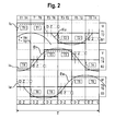
- Fig. 2 is a diagram showing schematically the waveform of motor current and back EMF and the switching states of the switches T1 to T6.
- the bold solid lines represent the switching states of the switches T1 to T6
- the broken lines represent the winding currents Iu, Iv and Iw through the winding strands 130U, 130V and 130W
- the thin solid line represent the back EMFs Eu , Ev, Ew generated in the windings 130U, 130V and 130W.
- the diagram in Fig. 2 shows the course during an electrical period T, which in turn is divided into six subperiods of the period T / 6, each corresponding to a 60 ° section.
- the three winding strands 130U, 130V and 130W are each driven with an offset of 120 °.
- the switches T1 and T4 are turned on and all other switches are turned off or non-turned on, so that the motor current Im flows through the winding line 130U through the neutral point 140 via the winding line 130V to the intermediate circuit ground.
- commutation from winding line 130V to winding line 130W occurs by turning off switch T4 and turning on switch T6.
- the switches T1 and T6 are turned on so that the motor current Im flows through the winding string 130U through the neutral point 140 via the winding string 130W to the intermediate circuit ground.
- a second commutation is made from winding line 130U to winding line 130V by turning off switch T1 and turning on switch T3.
- the switches T3 and T6 are turned on, so that the motor current Im flows through the winding line 130V through the neutral point 140 via the winding line 130W to the intermediate circuit ground. According to this pattern, therefore, two of the winding strands 130 are always live and the third winding strand 130 is de-energized.
- the motor controller 160 adjusts the timings of the commutations so that the movement of the rotor and the phase times of the applied voltages are synchronous and in phase.
- the back EMF of the motor that is, the voltages induced by the magnetic field of the rotor in the winding strands 130 of the stator to the position of the rotor.
- a characteristic variable for this purpose is the zero crossing of the back EMF, which in Fig. 2 each marked with "Z”.
- the commutation can be caused, for example delayed by a predetermined period of time after the detected zero crossing, this period of time can be speed and / or load-dependent.
- the times of commutation are marked with "C”.
- the winding current has a conditional by the inductance of the winding coil inertia.
- the current Iu through the winding string 130U increases over a certain rise time period when the switch T1 is turned on, and when the switch T1 is turned on, the current I out drops to zero over a period corresponding to the demagnetization time of the winding string 130U. Only at time “D” has the winding current decayed to zero.
- the commutation is thus characterized by the three events D, Z and C, ie time D of the demagnetization of the previously current leading strand, time Z of the zero crossing detection and time C of the actively triggered commutation after a predetermined time.
- the regulation of the power supply to the motor windings takes place via a pulse width modulation, PWM.
- PWM pulse width modulation
- the "duty cycle” is used as a measure of the duty cycle of the PWM modulated terminal voltage.
- the duty cycle is the ratio between duty cycle and cycle time and thus has a value between 0% and 100%.
- the PWM for driving the electric motor 100 can be done in the current mode or in the current mode or in the voltage mode.
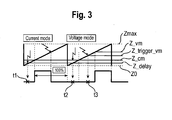
- Fig. 3 shows a diagram illustrating both methods, wherein the current mode in the left half and the voltage mode in the right half of the diagram is shown.
- a counter In the motor controller 160, a counter, not shown, generates reference values or counts which are incremented from an output value Z0 to a maximum value Zmax, such that over time a triangular pattern or trace results.
- the motor current is set by means of a comparator circuit in the two-point method. If the count value of the counter reaches the comparison value Z_cm, the pulse width modulated voltage is switched on. In current mode, the duty cycle results from the timing of the shutdown of the PWM pulse by the drive circuit. More specifically, for example, a current comparator, the desired current and the current actual current can be supplied. If the actual current reaches the setpoint current, the pulse width modulated voltage is switched off.
- a desired voltage is calculated by the motor controller 160 and the duty cycle of the PWM is impressed. This may be done, for example, by the motor controller 160 determining a comparison value Z_vm and comparing it with the current count, with the PWM voltage turning on when the count Z is greater than or equal to Z_vm and less than or equal to Zmax.
- the count values Z_delay and Z_trigger_vm indicate possible times t1, t2 and t3 for a measurement of the back EMF.
- the torque is impressed in the current mode and the speed in the voltage mode.
- the choice of operating mode is made depending on the load behavior and the requirements of the electric motor 100. Depending on whether high speed constancy, low noise, vibration or energy efficiency are desired, the appropriate mode is selected. In this case, the mode can be set when switching on the electric motor 100, or switched depending on the operating conditions. A mixture of operating modes is possible. It is advantageous to operate the motor in current mode during the starting phase in order to ensure an ideal adjustment of the torque during the starting phase. After running up, so for example when reaching a certain speed, the motor can then be switched to the voltage mode to use the property of the synchronous motor, embarkschteuern the torque fluctuations in the operation of the load angle.
- the electric motor 100 can be used for example as a drive of a compressor in a refrigerator.
- a compressor compresses a cooling medium by means of a reciprocating compressor.
- the cooling medium becomes by an inlet valve in one Inserted valve plate in a piston chamber, compressed by a piston driven by the electric motor and driven out of the piston chamber by an outlet valve in the valve plate.
- the piston Once per revolution, the piston thus reaches the top dead center and thus the point of maximum compression, in which the largest counter torque acts against the engine.
- the load profile of the load driven by the motor is thus very dynamic, with the maximum torque being a multiple, for example a fivefold, above the mean torque.
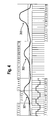
- Fig. 4 shows various compressor load profiles 301, 302 and 303 of such an electric motor 100.
- one revolution of the 6-pole electric motor 100 corresponds to three electric periods T, that is, one electrical period T per pole pair.
- Each of these electrical periods T corresponds to 6 electrical positions or switch positions, as indicated for the load profile 301.
- the characteristic BLDC control signal for a phase winding is indicated.
- the back pressure caused by the cooling medium depends on the operating state of the cooling circuit. Depending on how much of the cooling medium is liquefied and how much is still gaseous, the maximum counter torque is higher or lower.
- the rotor of the BLDC motor 100 can be positioned by a defined switch position.
- each of the six possible electrical positions 1 to 6 are associated with exactly three rotor positions. In which of these three rotor positions the rotor is positioned depends on the position in which the rotor came to a stop after the previous rotation. This position is unknown. If the rotor is now initially positioned in a position that is not sufficiently far from the maximum load, for example, in position 2 of the second electrical period in the load profile 301, then the torque generated by the starting ramp may not be large enough to that on the Motor acting counter-torque to overcome, and the startup fails.
- the rotor is first moved to a well-defined position before the start in the direction of rotation. In other words, the ambiguity of the rotor positions is first resolved.
- the method is based on the idea to first rotate the rotor with a low torque in a first direction of rotation, so that it gets stuck in a first standstill position before the maximum counter torque. Subsequently, the rotor is rotated and positioned by a certain angle of rotation in the opposite direction to a second standstill position. Finally, the motor is started up with a start-up ramp in the first direction of rotation.
- Fig. 5 illustrates the three steps or phases 401, 402 and 403 of this method and schematically shows the excitation currents 410, 420 and 430, which flow through the winding strands 130 in the individual phases.
- a first step 401 the rotor is driven in a first direction, which is identical to the later final direction of rotation of the rotor.
- the winding strands are acted upon by an excitation current, which generates a first torque which is smaller than a counter to the rotation of the rotor, maximum counter torque.
- Under the maximum counter torque is the torque at the time of the largest load during a complete revolution of the engine, ie in the compression point to understand.
- the rotation of the rotor can be done in this phase in step mode.
- each commutation corresponds to a step or an electrical subperiod.
- the individual steps 405 are also referred to as "sticking steps”.
- PWM pulse width modulation
- the generated first torque is not necessarily constant over time. In particular, in step mode, the torque can follow a particular profile. It is only important that the maximum value of the first torque is below the maximum counter torque.
- That the torque generated in each step 405 of this first phase 401 is smaller than the maximum counter torque can be achieved by appropriately setting the duty cycle of the PWM modulation and the duration of the individual steps 405.
- Control parameters that correspond to the maximum counter torque at idle ie at minimum pressure in the piston chamber, may be stored in a memory of the engine controller 160 and used in this first phase 401, whereby a sufficiently low torque can be ensured. Since the rotor can not overcome the maximum counter torque, it will stall in a first stoppage position before the compression point. This first standstill position is a few steps, e.g. two to four steps, before the compression point.
- the number of steps in this phase corresponds to 401 of the number of electrical sub-steps per revolution, since the rotor then remains in the same position regardless of the initial position. However, it is of course harmless to perform a larger number of adhesion steps 405. Furthermore, it is also sufficient to make a smaller number of adhesion steps 405. Assuming that it is at least two steps behind the compression point in its initial position and comes to a stop or hang at least two steps before the compression point, it is sufficient in the present example to perform 14 detention steps 405.
- next phase 402 of the method starting from the first standstill position, the rotor is moved by a certain number of steps in a second direction of rotation opposite to the first direction of rotation.
- the aim of this phase 402 is to bring the rotor in a defined standstill position, which is as far away in the direction of rotation from the compression point, so that in the subsequent phase the longest possible starting ramp can be provided.
- the positioning of the rotor against the later direction of rotation can be carried out again in step mode, it is irrelevant whether the torques generated in this case are greater or smaller than the maximum counter torque.
- the rotor can be rotated 12 steps counter-clockwise to come two steps past the compression point in the second standstill position to stand. It should be noted that in Fig. 5 For the sake of simplicity, only nine steps are shown. It is possible to use this step mode To start a switch position, which are only two or three steps behind the compression point. If necessary, these steps then correspond to the electrical positions which the rotor could not follow due to the high counter torque. The rotor thus remains in these steps in the first standstill position, and is "taken along" only in the subsequent steps.
- the rotor is rotationally started in the first direction of rotation, producing a torque greater than the maximum reaction torque.
- This third phase 403 may in turn be divided into three sections 431, 432 and 433.
- two of the winding strands 130 are supplied with an exciting current, the exciting current rising following a fixed rise ramp. Since the torque is substantially proportional to the current, this also increases accordingly from zero. This ensures that there is no oscillation of the rotor due to a sudden torque.
- Which of the two winding strands are driven depends on the end position of the rotor in phase 402, the winding strands being controlled such that the rotor moves in the opposite direction, ie in the final direction of rotation, in comparison to the phase 402.
- the drive of the winding strands takes place in accordance with a drive profile, which corresponds to a predetermined start ramp.
- the parameters e.g. Target current, times of the commutations and the like are predetermined and can be stored for example in a memory of the engine controller 160.
- the timing of the commutations do not depend on the back EMF, but are determined in advance.
- the commutation then takes place as a function of the determined back EMF, for example in each case a specific period of time after the determined one Zero crossing of the back EMF in the manner described above.
- This operation is also referred to as "auto-commutation" and corresponds to the illustration in FIG Fig. 2 ,
- the number of steps of the ramp in the second section 432 before switching to auto-commutation should be chosen so that the auto-commutation already takes several steps, e.g. three to seven steps, before the compression point is reached. For example, if the end position in the second phase 402 is sixteen steps before the compression point and the counter torque rises sharply after the twelfth step, then a 10-step start ramp is ideal until it switches to auto-commutation.
- the torque generated by the launch ramp in the second section 432 of the third phase 403 increases in a stepwise linear manner, which is to be understood as meaning that the difference between the generated torques or excitation currents of two successive switching states is substantially constant.
- the torque generated is always greater than or equal to the reaction torque acting on the engine, which results from inertial forces, frictional forces and compression forces.
- the torque generated by the launch ramp can also increase non-linearly. In particular, it can be adapted to the expected counter torque, so that the engine starts gently and then the generated torque is increased disproportionately in accordance with the steep increase in the counter torque. This can be done by taking the appropriate, possibly stored, driving parameters such as e.g. of the Dutycycles.
- the torque generated in the third section 433 is greater than the counter torque in the compression point, so that the rotor does not stop this time, but overcomes the compression point and starts up.
- the load profile depends, among other things, on the time for which the compressor was not switched on.
- the engine of the compressor must therefore start when starting against different load profiles, which are not always known. This is taken into account in the adaptive start-up of the motor described below.
- a first start-up is the starting method described above with the described three phases.
- a second type of start-up is a simple BLDC start, as it corresponds, for example, to the above-described third phase 403 without performing the phases 401 and 402.
- a third start-up is the restart after a predetermined timeout, which should ensure that relax the pressure conditions in the piston chamber and the maximum counter torque drops.
- a fourth startup procedure is startup with a changed parameter set.
- start-up mentioned can be combined with each other as required. For example, it is possible first to perform a simple BLDC start-up, and if unsuccessful, to perform the above-described tempering method with the described three phases. That a start attempt was unsuccessful can be determined, for example, by the fact that no zero crossing of the back EMF can be determined, that is, the back EMF has no zero crossing even after a predetermined, relatively long time.
- a somewhat more extensive adaptive procedure is as follows: In a first step, a predefined time-out is awaited. In a second step, a simple BLDC startup takes place with a set of parameters for unpressurised startup, ie a set of parameters based on an expected load profile for low backpressure. If this start-up fails, the entire start-up sequence with phases 401, 402 and 403 is carried out, again with a parameter set for unpressurised startup. If this start also fails, the BLDC startup with changed parameters and then the entire startup sequence with changed parameters will be carried out first. These changed parameters are based on an expected load profile for high back pressure. If these attempts are also unsuccessful, the time-out can again be waited for, and the sequence can be carried out anew, if necessary with parameters changed again or a longer time-out.
- Examples of possible parameters that can be varied between the start-up sequences are: the start position of the rotor at the start of the BLDC start, the duration of the energization in the start position, the duty cycle and the change of the duty cycle during the rotor alignment phase, ie during the section 431, the starting ramp in section 432, in particular the times of the individual commutations during this section, the curve shape of this launch ramp, the number of steps to auto-commutation or to the measurement of the back EMF, the number of detected EMF zero crossings to the change in the auto-commutation, the operating mode and the duty cycle in the ramp or the change of the Dutycycles with the speed, the initial values at the point of the switching for the Demagnetmaschineszeit and the first Kommutêtszeit.
- Further possible parameters are the times until the activation of the speed controller, up to the possible changeover of the operating mode and until the use of speed-dependent factors, as well as all calculation parameters in operation for determining the commutation time.
- the engine can be started reliably even with unknown load conditions.
Landscapes
- Engineering & Computer Science (AREA)
- Power Engineering (AREA)
- Control Of Motors That Do Not Use Commutators (AREA)
- Motor And Converter Starters (AREA)
Priority Applications (1)
| Application Number | Priority Date | Filing Date | Title |
|---|---|---|---|
| PL11722104T PL2583380T3 (pl) | 2010-06-17 | 2011-05-31 | Sposób i urządzenie do uruchamiania silnika elektrycznego |
Applications Claiming Priority (2)
| Application Number | Priority Date | Filing Date | Title |
|---|---|---|---|
| DE102010030239A DE102010030239A1 (de) | 2010-06-17 | 2010-06-17 | Verfahren und Vorrichtung zum Anlassen eines Elektromotors |
| PCT/EP2011/058967 WO2011157553A2 (de) | 2010-06-17 | 2011-05-31 | Verfahren und vorrichtung zum anlassen eines elektromotors |
Publications (2)
| Publication Number | Publication Date |
|---|---|
| EP2583380A2 EP2583380A2 (de) | 2013-04-24 |
| EP2583380B1 true EP2583380B1 (de) | 2014-08-06 |
Family
ID=44119385
Family Applications (1)
| Application Number | Title | Priority Date | Filing Date |
|---|---|---|---|
| EP11722104.4A Active EP2583380B1 (de) | 2010-06-17 | 2011-05-31 | Verfahren und vorrichtung zum anlassen eines elektromotors |
Country Status (8)
| Country | Link |
|---|---|
| US (1) | US8896258B2 (zh) |
| EP (1) | EP2583380B1 (zh) |
| CN (1) | CN102948069B (zh) |
| DE (1) | DE102010030239A1 (zh) |
| ES (1) | ES2493927T3 (zh) |
| PL (1) | PL2583380T3 (zh) |
| RU (1) | RU2532532C2 (zh) |
| WO (1) | WO2011157553A2 (zh) |
Families Citing this family (12)
| Publication number | Priority date | Publication date | Assignee | Title |
|---|---|---|---|---|
| US8712595B2 (en) * | 2011-01-18 | 2014-04-29 | General Electric Company | Dynamic load profiling in a power network |
| JP5216940B1 (ja) | 2011-10-17 | 2013-06-19 | パナソニック株式会社 | モータ駆動システムおよびその制御方法 |
| DE102013018859A1 (de) * | 2013-11-07 | 2015-07-09 | Elmos Semiconductor Aktiengesellschaft | Verfahren zur Synchronisation einer Ansteuerelektronik auf einen sich drehenden Motor bei sinusförmiger Ansteuerung |
| DE102014226285A1 (de) * | 2013-12-20 | 2015-06-25 | Semiconductor Components Industries, Llc | Motorsteuerschaltung und Verfahren |
| DE102014006409A1 (de) | 2014-03-27 | 2015-10-15 | Elmos Semiconductor Aktiengesellschaft | Verfahren zur Synchronisation einer Ansteuerelektronik auf einen sich drehenden Motor bei sinusförmiger Ansteuerung |
| CN104022709B (zh) * | 2014-05-22 | 2018-07-06 | 广东威灵电机制造有限公司 | 一种永磁同步电机中转子初始位置的定位方法及系统 |
| DE102014217006A1 (de) * | 2014-08-26 | 2016-03-03 | BSH Hausgeräte GmbH | Verfahren zum Anhalten eines Verdichters und Verdichter eines Kältegerätes |
| DE102014217005A1 (de) * | 2014-08-26 | 2016-03-03 | BSH Hausgeräte GmbH | Verfahren zum Bremsen eines Verdichters und Verdichter eines Kältegerätes, Klimageräts oder einer Wärmepumpe sowie Kältegerätes, Klimageräts oder Wärmepumpe damit |
| DE102015208259A1 (de) | 2015-05-05 | 2016-11-10 | BSH Hausgeräte GmbH | Haushaltsgerät mit einem elektrischen Antrieb |
| CN109997306B (zh) * | 2016-10-17 | 2022-05-17 | 西门子股份公司 | 用软启动使三相电机对准的方法和三相电机 |
| ES2880621T3 (es) | 2016-12-02 | 2021-11-25 | Evonik Degussa Gmbh | Productos preimpregnados de poliuretano 1K estables al almacenamiento y cuerpos moldeados a partir de la composición de poliuretano producidos a partir de estos |
| RU2654631C1 (ru) * | 2017-04-17 | 2018-05-21 | федеральное государственное бюджетное образовательное учреждение высшего образования "Уфимский государственный авиационный технический университет" | Способ пуска синхронных двигателей с инкорпорированными магнитами (варианты) |
Family Cites Families (15)
| Publication number | Priority date | Publication date | Assignee | Title |
|---|---|---|---|---|
| US4565957A (en) * | 1983-06-30 | 1986-01-21 | Borg-Warner Corporation | Method and system for starting a motor-commutated SCR inverter |
| SU1317630A1 (ru) | 1985-07-17 | 1987-06-15 | Московский энергетический институт | Вентильный электропривод |
| JP2547061B2 (ja) * | 1988-03-15 | 1996-10-23 | 日本電産株式会社 | 直流ブラシレスモータの起動回転制御方法 |
| BR8901539A (pt) | 1989-03-27 | 1990-10-30 | Brasil Compressores Sa | Processo e circuito eletronico para controle de motor de corrente continua sem escovas |
| US5177416A (en) * | 1990-06-20 | 1993-01-05 | Matsushita Electric Industrial Co., Ltd. | Brushless dc motor |
| DE4122109A1 (de) * | 1991-07-04 | 1993-01-07 | Standard Elektrik Lorenz Ag | Verfahren und schaltungsanordnung zur anlaufsteuerung eines elektronisch kommutierten gleichstrommotors |
| RU2096906C1 (ru) | 1994-02-18 | 1997-11-20 | Научно-производственное предприятие "Тонар" | Система управления двигателем с электронной коммутацией |
| EP1016207B1 (de) * | 1996-01-10 | 2003-05-14 | Papst-Motoren Gmbh & Co. Kg | Verfahren zum starten eines elektronisch kommutierten gleichstrommotors, und motor zur durchführung eines solchen verfahrens |
| BR9706175A (pt) | 1997-12-12 | 1999-09-21 | Brasil Compressores Sa | Sistema para controle de acionamento de motor elétrico. |
| IT1301915B1 (it) | 1998-08-07 | 2000-07-07 | Sicce Spa | Procedimento per l'avviamento e l'alimentazione a regime di un motoresincrono a magneti permanenti particolarmente per l'azionamento di una |
| BR9902182A (pt) | 1999-03-18 | 2000-10-17 | Brasil Compressores Sa | Aperfeiçoamento em sistema de partida de motor elétrico |
| DE10215428A1 (de) | 2002-04-08 | 2003-10-23 | Heidenhain Gmbh Dr Johannes | Verfahren zur Bestimmung der Rotorlage eines Synchronmotors |
| ATE371984T1 (de) * | 2004-05-12 | 2007-09-15 | Ebm Papst St Georgen Gmbh & Co | Elektronisch kommutierter zweipulsiger motor und verfahren zum starten eines solchen motors |
| RU52451U1 (ru) | 2005-03-22 | 2006-03-27 | Общество с ограниченной ответственностью "АСКОМ" | Устройство компрессорной станции с плавным запуском компрессоров |
| US7652441B2 (en) | 2005-07-01 | 2010-01-26 | International Rectifier Corporation | Method and system for starting a sensorless motor |
-
2010
- 2010-06-17 DE DE102010030239A patent/DE102010030239A1/de not_active Withdrawn
-
2011
- 2011-05-31 RU RU2012154346/07A patent/RU2532532C2/ru not_active IP Right Cessation
- 2011-05-31 WO PCT/EP2011/058967 patent/WO2011157553A2/de active Application Filing
- 2011-05-31 PL PL11722104T patent/PL2583380T3/pl unknown
- 2011-05-31 CN CN201180029801.5A patent/CN102948069B/zh active Active
- 2011-05-31 US US13/702,589 patent/US8896258B2/en active Active
- 2011-05-31 ES ES11722104.4T patent/ES2493927T3/es active Active
- 2011-05-31 EP EP11722104.4A patent/EP2583380B1/de active Active
Also Published As
| Publication number | Publication date |
|---|---|
| US20130076279A1 (en) | 2013-03-28 |
| EP2583380A2 (de) | 2013-04-24 |
| WO2011157553A2 (de) | 2011-12-22 |
| WO2011157553A3 (de) | 2012-06-14 |
| RU2532532C2 (ru) | 2014-11-10 |
| DE102010030239A1 (de) | 2011-12-22 |
| CN102948069A (zh) | 2013-02-27 |
| ES2493927T3 (es) | 2014-09-12 |
| RU2012154346A (ru) | 2014-07-27 |
| PL2583380T3 (pl) | 2015-01-30 |
| CN102948069B (zh) | 2015-09-02 |
| US8896258B2 (en) | 2014-11-25 |
Similar Documents
| Publication | Publication Date | Title |
|---|---|---|
| EP2583380B1 (de) | Verfahren und vorrichtung zum anlassen eines elektromotors | |
| EP3186880B1 (de) | Verfahren zum anhalten eines verdichters und verdichter eines kältegerätes | |
| EP3186879B1 (de) | Verfahren zum bremsen eines verdichters und verdichter eines kältegerätes, klimageräts oder einer wärmepumpe sowie kältegerätes, klimageräts oder wärmepumpe damit | |
| DE102006026560B4 (de) | Anlaufverfahren für einen sensor- und bürstenlosen Gleichstrommotor | |
| DE69730505T2 (de) | Betätigungs- und regelverfahren und vorrichtung, insbesondere für synchrone, permanentmagnet-motoren | |
| DE60019850T2 (de) | Regelungsverfahren für einen geschalteten Reluktanzmotor und Reluktanzmotor mit geringem Spitzenstrom | |
| EP2583379B1 (de) | Verfahren und vorrichtung zur anpassung eines drehzahlbereichs eines elektromotors | |
| EP3433926B1 (de) | Verfahren zur rotorpositionserkennung eines bldc motors eines hubkolbenverdichters, verdichtersteuerung zur durchführung des verfahrens und kältegerät mit dieser | |
| EP1443635B1 (de) | Verfahren zum Steuern des Zündwinkels und einphasiger wechselstromversorgter Elektromotor | |
| WO2016023588A1 (de) | Verfahren zum anlassen eines kraftfahrzeug-zusatzaggregats-antiebsmotors und karftfahrzeug-zusatzaggregat-antriebsmotor | |
| WO2002080348A1 (de) | Verfahren zur steuerung eines elektronish kommutierten gleichstrommotors | |
| DE102015211499A1 (de) | Verfahren zum Betreiben eines bürstenlosen Elektromotors | |
| EP2680432A2 (de) | Verfahren zur Ansteuerung eines Schrittmotors | |
| DE102018119729A1 (de) | Verfahren zum Ansteuern eines Elektromotors und Elektromotor | |
| EP3718202B1 (de) | Verfahren zum betreiben einer antriebseinrichtung für ein kraftfahrzeug sowie entsprechende antriebseinrichtung für ein kraftfahrzeug | |
| DE102021214720A1 (de) | Steuereinrichtung zum Steuern eines bürstenlosen Gleichstrommotors unter Verwendung einer Totzeit-Kompensation | |
| EP4037179A1 (de) | Verfahren zum ansteuern eines mindestens zweiphasigen bürstenlosen motors | |
| DE102018119723A1 (de) | Verfahren zum Ansteuern eines Elektromotors und Elektromotor | |
| DE102019101453A1 (de) | Verfahren zur Wirkungsgradoptimierung einer elektrisch kommutierten Maschine | |
| DE102017201272A1 (de) | Bürstenloser Gleichstrommotor und Verfahren zum Betrieb eines bürstenlosen Gleichstrommotors | |
| EP4331104A1 (de) | Verfahren zum anlaufen eines rotors eines klauenpolmotors | |
| WO2018054423A1 (de) | Stelleinheit einer brennkraftmaschine | |
| EP3331157A1 (de) | Verfahren und ansteuereinheit zur ansteuerung eines geschalteten reluktanzmotors | |
| EP3312986A1 (de) | Verkürzung der ausrichtphase bei einem reluktanzmotor | |
| EP1981165A2 (de) | Verfahren zur Steuerung eines Reluktanzmotors |
Legal Events
| Date | Code | Title | Description |
|---|---|---|---|
| PUAI | Public reference made under article 153(3) epc to a published international application that has entered the european phase |
Free format text: ORIGINAL CODE: 0009012 |
|
| 17P | Request for examination filed |
Effective date: 20130117 |
|
| AK | Designated contracting states |
Kind code of ref document: A2 Designated state(s): AL AT BE BG CH CY CZ DE DK EE ES FI FR GB GR HR HU IE IS IT LI LT LU LV MC MK MT NL NO PL PT RO RS SE SI SK SM TR |
|
| DAX | Request for extension of the european patent (deleted) | ||
| RIC1 | Information provided on ipc code assigned before grant |
Ipc: H02P 6/20 20060101AFI20140127BHEP Ipc: H02P 1/40 20060101ALI20140127BHEP |
|
| GRAP | Despatch of communication of intention to grant a patent |
Free format text: ORIGINAL CODE: EPIDOSNIGR1 |
|
| INTG | Intention to grant announced |
Effective date: 20140318 |
|
| GRAS | Grant fee paid |
Free format text: ORIGINAL CODE: EPIDOSNIGR3 |
|
| GRAA | (expected) grant |
Free format text: ORIGINAL CODE: 0009210 |
|
| AK | Designated contracting states |
Kind code of ref document: B1 Designated state(s): AL AT BE BG CH CY CZ DE DK EE ES FI FR GB GR HR HU IE IS IT LI LT LU LV MC MK MT NL NO PL PT RO RS SE SI SK SM TR |
|
| REG | Reference to a national code |
Ref country code: GB Ref legal event code: FG4D Free format text: NOT ENGLISH |
|
| REG | Reference to a national code |
Ref country code: CH Ref legal event code: EP Ref country code: AT Ref legal event code: REF Ref document number: 681427 Country of ref document: AT Kind code of ref document: T Effective date: 20140815 |
|
| REG | Reference to a national code |
Ref country code: IE Ref legal event code: FG4D Free format text: LANGUAGE OF EP DOCUMENT: GERMAN |
|
| REG | Reference to a national code |
Ref country code: ES Ref legal event code: FG2A Ref document number: 2493927 Country of ref document: ES Kind code of ref document: T3 Effective date: 20140912 |
|
| REG | Reference to a national code |
Ref country code: DE Ref legal event code: R096 Ref document number: 502011003965 Country of ref document: DE Effective date: 20140918 |
|
| REG | Reference to a national code |
Ref country code: NL Ref legal event code: VDEP Effective date: 20140806 |
|
| REG | Reference to a national code |
Ref country code: LT Ref legal event code: MG4D |
|
| PG25 | Lapsed in a contracting state [announced via postgrant information from national office to epo] |
Ref country code: SE Free format text: LAPSE BECAUSE OF FAILURE TO SUBMIT A TRANSLATION OF THE DESCRIPTION OR TO PAY THE FEE WITHIN THE PRESCRIBED TIME-LIMIT Effective date: 20140806 Ref country code: NO Free format text: LAPSE BECAUSE OF FAILURE TO SUBMIT A TRANSLATION OF THE DESCRIPTION OR TO PAY THE FEE WITHIN THE PRESCRIBED TIME-LIMIT Effective date: 20141106 Ref country code: BG Free format text: LAPSE BECAUSE OF FAILURE TO SUBMIT A TRANSLATION OF THE DESCRIPTION OR TO PAY THE FEE WITHIN THE PRESCRIBED TIME-LIMIT Effective date: 20141106 Ref country code: LT Free format text: LAPSE BECAUSE OF FAILURE TO SUBMIT A TRANSLATION OF THE DESCRIPTION OR TO PAY THE FEE WITHIN THE PRESCRIBED TIME-LIMIT Effective date: 20140806 Ref country code: GR Free format text: LAPSE BECAUSE OF FAILURE TO SUBMIT A TRANSLATION OF THE DESCRIPTION OR TO PAY THE FEE WITHIN THE PRESCRIBED TIME-LIMIT Effective date: 20141107 Ref country code: PT Free format text: LAPSE BECAUSE OF FAILURE TO SUBMIT A TRANSLATION OF THE DESCRIPTION OR TO PAY THE FEE WITHIN THE PRESCRIBED TIME-LIMIT Effective date: 20141209 Ref country code: FI Free format text: LAPSE BECAUSE OF FAILURE TO SUBMIT A TRANSLATION OF THE DESCRIPTION OR TO PAY THE FEE WITHIN THE PRESCRIBED TIME-LIMIT Effective date: 20140806 |
|
| REG | Reference to a national code |
Ref country code: PL Ref legal event code: T3 |
|
| PG25 | Lapsed in a contracting state [announced via postgrant information from national office to epo] |
Ref country code: LV Free format text: LAPSE BECAUSE OF FAILURE TO SUBMIT A TRANSLATION OF THE DESCRIPTION OR TO PAY THE FEE WITHIN THE PRESCRIBED TIME-LIMIT Effective date: 20140806 Ref country code: HR Free format text: LAPSE BECAUSE OF FAILURE TO SUBMIT A TRANSLATION OF THE DESCRIPTION OR TO PAY THE FEE WITHIN THE PRESCRIBED TIME-LIMIT Effective date: 20140806 Ref country code: CY Free format text: LAPSE BECAUSE OF FAILURE TO SUBMIT A TRANSLATION OF THE DESCRIPTION OR TO PAY THE FEE WITHIN THE PRESCRIBED TIME-LIMIT Effective date: 20140806 Ref country code: NL Free format text: LAPSE BECAUSE OF FAILURE TO SUBMIT A TRANSLATION OF THE DESCRIPTION OR TO PAY THE FEE WITHIN THE PRESCRIBED TIME-LIMIT Effective date: 20140806 Ref country code: IS Free format text: LAPSE BECAUSE OF FAILURE TO SUBMIT A TRANSLATION OF THE DESCRIPTION OR TO PAY THE FEE WITHIN THE PRESCRIBED TIME-LIMIT Effective date: 20141206 Ref country code: RS Free format text: LAPSE BECAUSE OF FAILURE TO SUBMIT A TRANSLATION OF THE DESCRIPTION OR TO PAY THE FEE WITHIN THE PRESCRIBED TIME-LIMIT Effective date: 20140806 |
|
| REG | Reference to a national code |
Ref country code: CH Ref legal event code: PFA Owner name: BSH HAUSGERAETE GMBH, DE Free format text: FORMER OWNER: BSH BOSCH UND SIEMENS HAUSGERAETE GMBH, DE |
|
| RAP2 | Party data changed (patent owner data changed or rights of a patent transferred) |
Owner name: BSH HAUSGERAETE GMBH |
|
| PG25 | Lapsed in a contracting state [announced via postgrant information from national office to epo] |
Ref country code: SK Free format text: LAPSE BECAUSE OF FAILURE TO SUBMIT A TRANSLATION OF THE DESCRIPTION OR TO PAY THE FEE WITHIN THE PRESCRIBED TIME-LIMIT Effective date: 20140806 Ref country code: DK Free format text: LAPSE BECAUSE OF FAILURE TO SUBMIT A TRANSLATION OF THE DESCRIPTION OR TO PAY THE FEE WITHIN THE PRESCRIBED TIME-LIMIT Effective date: 20140806 Ref country code: EE Free format text: LAPSE BECAUSE OF FAILURE TO SUBMIT A TRANSLATION OF THE DESCRIPTION OR TO PAY THE FEE WITHIN THE PRESCRIBED TIME-LIMIT Effective date: 20140806 Ref country code: CZ Free format text: LAPSE BECAUSE OF FAILURE TO SUBMIT A TRANSLATION OF THE DESCRIPTION OR TO PAY THE FEE WITHIN THE PRESCRIBED TIME-LIMIT Effective date: 20140806 Ref country code: RO Free format text: LAPSE BECAUSE OF FAILURE TO SUBMIT A TRANSLATION OF THE DESCRIPTION OR TO PAY THE FEE WITHIN THE PRESCRIBED TIME-LIMIT Effective date: 20140806 |
|
| REG | Reference to a national code |
Ref country code: DE Ref legal event code: R097 Ref document number: 502011003965 Country of ref document: DE |
|
| REG | Reference to a national code |
Ref country code: FR Ref legal event code: PLFP Year of fee payment: 5 |
|
| REG | Reference to a national code |
Ref country code: DE Ref legal event code: R081 Ref document number: 502011003965 Country of ref document: DE Owner name: BSH HAUSGERAETE GMBH, DE Free format text: FORMER OWNER: BSH BOSCH UND SIEMENS HAUSGERAETE GMBH, 81739 MUENCHEN, DE Effective date: 20150413 |
|
| REG | Reference to a national code |
Ref country code: ES Ref legal event code: PC2A Owner name: BSH HAUSGERATE GMBH Effective date: 20150529 |
|
| PLBE | No opposition filed within time limit |
Free format text: ORIGINAL CODE: 0009261 |
|
| STAA | Information on the status of an ep patent application or granted ep patent |
Free format text: STATUS: NO OPPOSITION FILED WITHIN TIME LIMIT |
|
| 26N | No opposition filed |
Effective date: 20150507 |
|
| REG | Reference to a national code |
Ref country code: FR Ref legal event code: CD Owner name: BSH HAUSGERATE GMBH, DE Effective date: 20151022 |
|
| PG25 | Lapsed in a contracting state [announced via postgrant information from national office to epo] |
Ref country code: SI Free format text: LAPSE BECAUSE OF FAILURE TO SUBMIT A TRANSLATION OF THE DESCRIPTION OR TO PAY THE FEE WITHIN THE PRESCRIBED TIME-LIMIT Effective date: 20140806 |
|
| REG | Reference to a national code |
Ref country code: CH Ref legal event code: PL |
|
| PG25 | Lapsed in a contracting state [announced via postgrant information from national office to epo] |
Ref country code: LU Free format text: LAPSE BECAUSE OF FAILURE TO SUBMIT A TRANSLATION OF THE DESCRIPTION OR TO PAY THE FEE WITHIN THE PRESCRIBED TIME-LIMIT Effective date: 20150531 Ref country code: MC Free format text: LAPSE BECAUSE OF FAILURE TO SUBMIT A TRANSLATION OF THE DESCRIPTION OR TO PAY THE FEE WITHIN THE PRESCRIBED TIME-LIMIT Effective date: 20140806 Ref country code: CH Free format text: LAPSE BECAUSE OF NON-PAYMENT OF DUE FEES Effective date: 20150531 Ref country code: LI Free format text: LAPSE BECAUSE OF NON-PAYMENT OF DUE FEES Effective date: 20150531 |
|
| REG | Reference to a national code |
Ref country code: IE Ref legal event code: MM4A |
|
| PG25 | Lapsed in a contracting state [announced via postgrant information from national office to epo] |
Ref country code: IE Free format text: LAPSE BECAUSE OF NON-PAYMENT OF DUE FEES Effective date: 20150531 |
|
| REG | Reference to a national code |
Ref country code: FR Ref legal event code: PLFP Year of fee payment: 6 |
|
| PGFP | Annual fee paid to national office [announced via postgrant information from national office to epo] |
Ref country code: GB Payment date: 20160523 Year of fee payment: 6 Ref country code: ES Payment date: 20160523 Year of fee payment: 6 |
|
| PGFP | Annual fee paid to national office [announced via postgrant information from national office to epo] |
Ref country code: FR Payment date: 20160523 Year of fee payment: 6 |
|
| PG25 | Lapsed in a contracting state [announced via postgrant information from national office to epo] |
Ref country code: MT Free format text: LAPSE BECAUSE OF FAILURE TO SUBMIT A TRANSLATION OF THE DESCRIPTION OR TO PAY THE FEE WITHIN THE PRESCRIBED TIME-LIMIT Effective date: 20140806 |
|
| PG25 | Lapsed in a contracting state [announced via postgrant information from national office to epo] |
Ref country code: HU Free format text: LAPSE BECAUSE OF FAILURE TO SUBMIT A TRANSLATION OF THE DESCRIPTION OR TO PAY THE FEE WITHIN THE PRESCRIBED TIME-LIMIT; INVALID AB INITIO Effective date: 20110531 Ref country code: SM Free format text: LAPSE BECAUSE OF FAILURE TO SUBMIT A TRANSLATION OF THE DESCRIPTION OR TO PAY THE FEE WITHIN THE PRESCRIBED TIME-LIMIT Effective date: 20140806 |
|
| REG | Reference to a national code |
Ref country code: AT Ref legal event code: MM01 Ref document number: 681427 Country of ref document: AT Kind code of ref document: T Effective date: 20160531 |
|
| PG25 | Lapsed in a contracting state [announced via postgrant information from national office to epo] |
Ref country code: BE Free format text: LAPSE BECAUSE OF NON-PAYMENT OF DUE FEES Effective date: 20150531 |
|
| PG25 | Lapsed in a contracting state [announced via postgrant information from national office to epo] |
Ref country code: AT Free format text: LAPSE BECAUSE OF NON-PAYMENT OF DUE FEES Effective date: 20160531 |
|
| PGFP | Annual fee paid to national office [announced via postgrant information from national office to epo] |
Ref country code: IT Payment date: 20170524 Year of fee payment: 7 Ref country code: PL Payment date: 20170522 Year of fee payment: 7 |
|
| PGFP | Annual fee paid to national office [announced via postgrant information from national office to epo] |
Ref country code: TR Payment date: 20170530 Year of fee payment: 7 |
|
| GBPC | Gb: european patent ceased through non-payment of renewal fee |
Effective date: 20170531 |
|
| REG | Reference to a national code |
Ref country code: FR Ref legal event code: ST Effective date: 20180131 |
|
| PG25 | Lapsed in a contracting state [announced via postgrant information from national office to epo] |
Ref country code: GB Free format text: LAPSE BECAUSE OF NON-PAYMENT OF DUE FEES Effective date: 20170531 |
|
| PG25 | Lapsed in a contracting state [announced via postgrant information from national office to epo] |
Ref country code: FR Free format text: LAPSE BECAUSE OF NON-PAYMENT OF DUE FEES Effective date: 20170531 |
|
| REG | Reference to a national code |
Ref country code: ES Ref legal event code: FD2A Effective date: 20180627 |
|
| PG25 | Lapsed in a contracting state [announced via postgrant information from national office to epo] |
Ref country code: MK Free format text: LAPSE BECAUSE OF FAILURE TO SUBMIT A TRANSLATION OF THE DESCRIPTION OR TO PAY THE FEE WITHIN THE PRESCRIBED TIME-LIMIT Effective date: 20140806 |
|
| PG25 | Lapsed in a contracting state [announced via postgrant information from national office to epo] |
Ref country code: ES Free format text: LAPSE BECAUSE OF NON-PAYMENT OF DUE FEES Effective date: 20170601 |
|
| PG25 | Lapsed in a contracting state [announced via postgrant information from national office to epo] |
Ref country code: AL Free format text: LAPSE BECAUSE OF FAILURE TO SUBMIT A TRANSLATION OF THE DESCRIPTION OR TO PAY THE FEE WITHIN THE PRESCRIBED TIME-LIMIT Effective date: 20140806 |
|
| PG25 | Lapsed in a contracting state [announced via postgrant information from national office to epo] |
Ref country code: IT Free format text: LAPSE BECAUSE OF NON-PAYMENT OF DUE FEES Effective date: 20180531 |
|
| PG25 | Lapsed in a contracting state [announced via postgrant information from national office to epo] |
Ref country code: PL Free format text: LAPSE BECAUSE OF NON-PAYMENT OF DUE FEES Effective date: 20180531 |
|
| PG25 | Lapsed in a contracting state [announced via postgrant information from national office to epo] |
Ref country code: TR Free format text: LAPSE BECAUSE OF NON-PAYMENT OF DUE FEES Effective date: 20180531 |
|
| REG | Reference to a national code |
Ref country code: DE Ref legal event code: R084 Ref document number: 502011003965 Country of ref document: DE |
|
| PGFP | Annual fee paid to national office [announced via postgrant information from national office to epo] |
Ref country code: DE Payment date: 20230531 Year of fee payment: 13 |