EP2582544B1 - Stake anchoring arrangement - Google Patents
Stake anchoring arrangement Download PDFInfo
- Publication number
- EP2582544B1 EP2582544B1 EP11796056.7A EP11796056A EP2582544B1 EP 2582544 B1 EP2582544 B1 EP 2582544B1 EP 11796056 A EP11796056 A EP 11796056A EP 2582544 B1 EP2582544 B1 EP 2582544B1
- Authority
- EP
- European Patent Office
- Prior art keywords
- stake
- catch
- wedge member
- wedge
- socket
- Prior art date
- Legal status (The legal status is an assumption and is not a legal conclusion. Google has not performed a legal analysis and makes no representation as to the accuracy of the status listed.)
- Active
Links
Images




Classifications
-
- B—PERFORMING OPERATIONS; TRANSPORTING
- B60—VEHICLES IN GENERAL
- B60P—VEHICLES ADAPTED FOR LOAD TRANSPORTATION OR TO TRANSPORT, TO CARRY, OR TO COMPRISE SPECIAL LOADS OR OBJECTS
- B60P7/00—Securing or covering of load on vehicles
- B60P7/06—Securing of load
- B60P7/08—Securing to the vehicle floor or sides
- B60P7/0892—Securing to the vehicle floor or sides by preventing lateral movement of the load, e.g. using stop blocks
-
- B—PERFORMING OPERATIONS; TRANSPORTING
- B60—VEHICLES IN GENERAL
- B60P—VEHICLES ADAPTED FOR LOAD TRANSPORTATION OR TO TRANSPORT, TO CARRY, OR TO COMPRISE SPECIAL LOADS OR OBJECTS
- B60P7/00—Securing or covering of load on vehicles
- B60P7/06—Securing of load
- B60P7/08—Securing to the vehicle floor or sides
- B60P7/12—Securing to the vehicle floor or sides the load being tree-trunks, beams, drums, tubes, or the like
-
- B—PERFORMING OPERATIONS; TRANSPORTING
- B60—VEHICLES IN GENERAL
- B60P—VEHICLES ADAPTED FOR LOAD TRANSPORTATION OR TO TRANSPORT, TO CARRY, OR TO COMPRISE SPECIAL LOADS OR OBJECTS
- B60P7/00—Securing or covering of load on vehicles
- B60P7/06—Securing of load
- B60P7/135—Securing or supporting by load bracing means
- B60P7/15—Securing or supporting by load bracing means the load bracing means comprising a movable bar
-
- B—PERFORMING OPERATIONS; TRANSPORTING
- B62—LAND VEHICLES FOR TRAVELLING OTHERWISE THAN ON RAILS
- B62D—MOTOR VEHICLES; TRAILERS
- B62D33/00—Superstructures for load-carrying vehicles
- B62D33/02—Platforms; Open load compartments
- B62D33/0207—Connections of movable or detachable racks or stanchions to platforms
- B62D33/0215—Connections of movable or detachable racks or stanchions to platforms for log hauling vehicles
Definitions
- the present invention relates in general to a disengageable anchoring of a load shifting protection in a load carrying structure of a truck, a railway wagon or any other craft.
- the present invention relates to a stake anchoring arrangement for the anchoring of a stake in a load carrying structure, the stake anchoring arrangement comprising an upwardly open socket which is arranged to be connected to the load carrying structure and which comprises a front wall and a back wall opposite the front wall, furthermore the stake anchoring arrangement comprises a wedge assembly that is arranged to act between the front wall of the socket and a stake axially lowerable into the socket.
- An elucidating example which shall not be considered limiting for the present invention, is a truck having a flat loading platform.
- the truck shall at one occasion transport timber, the truck driver placing a row of a number of upright stakes along each of the two longitudinal edges of the loading platform. Thereafter the timber is placed on the loading platform oriented in the longitudinal direction of the truck, the stakes acting as load shifting protection in the transverse direction of the truck.
- the truck driver After the timber has been unloaded from the truck it shall transport big laying cement culverts, the truck driver placing stakes in front of, behind and on each side of the cement culverts, thereby the stakes acts as load shifting protection in the longitudinal direction and the transverse direction of the truck. Thereafter the truck shall transport big upright boards, the truck driver placing two longitudinal rows of stakes in the middle of the loading platform. The boards are placed between the two adjacent rows of stakes, the stakes acting as load shifting protection in the transverse direction of the truck. It is readily realized that the loading platform must have a stake anchoring arrangement that is flexible in such a way that the driver must be able to adapt the appearance/configuration of the loading platform in an easy way out on the roads without the need of work shop tools.
- Flexible, disengageable anchoring of stakes in stake anchoring arrangements can be divided into two main groups, a first group using a locking mechanism arranged in the stake and a second group using a locking mechanism arranged in or at the socket.
- Example of disengageable anchoring in stake anchoring arrangements belonging to the first group are shown in EP0244383 and SE451987 , wherein the locking mechanism is arranged in the stake and after the stake has been lowered into the socket the driver activates the locking mechanism by turning a control by means of a large special wrench. The locking mechanism then engages the socket and prevents the stake from jumping out of the socket.
- a disadvantage is that each separate stake must comprise a locking mechanism making each stake expensive and complicated to manufacture, at the same time as each stake becomes unnecessarily heavy and cumbersome for the driver to handle.
- such solutions are also suffer from the problem that the stakes rattle and shake in the sockets, especially when without load when the truck is driven unloaded, which is irritating for the driver and damageable for the stake as well as for the socket.
- Example of disengageable anchoring of stake anchoring arrangements belonging to the second group are shown in SE451009 and WO93/24344 , in which the stakes in the lower end thereof comprises threaded holes.
- a bolt is arranged in a through hole in the bottom of the socket and screwed into the threaded hole of the stake from below, the bolt pulling the stake downwards towards the bottom of the socket.
- these solutions suffer from the problem that the stakes when without load rattle and shake in the sockets, which also may result in the bolt coming loose.
- a primary object of the invention is to provide an improved stake anchoring arrangement of the initially defined type, which admits automatic, disengageable anchoring of the stake in the socket during lowering of the stake therein, which in other words have in view that no tools are needed in order to anchor the stake in the socket.
- the initially defined stake anchoring arrangement which is characterized in that the front wall incline in the direction of the back wall, and in that the wedge assembly comprises a catch, a spring member and a wedge member, the catch being turnably arranged about a pivot from a primed position to an activated position under the action of the axially lowerable stake, thereto the catch is arranged when in the primed position to maintain the wedge member in a lower position and when in the activated position set the wedge member in a disengaged condition, the wedge member when in the disengaged condition being axially displaceable from the lower position to an upper position under the action of the spring member in order to wedge said axially lowerable stake between the wedge member and the back wall of the socket.
- the present invention is based on the insight that by using the stake to activate the locking mechanism, which in its turn locks the stake the more the stake rattle and shake, an easy handling of the stakes is obtained without the need of special tools or procedures.
- the catch comprises a shoulder arranged to be activated by the axially lowerable stake and means for engagement with the wedge member.
- the wedge member comprises a first surface arranged to abut the front wall of the socket, a second surface arranged to abut the axially lowerable stake and means for engagement with the catch. Which entail that the stake upon lowering thereof will activate the wedge assembly, whereupon the wedge member will lock the stake in the socket.
- the wedge assembly is arranged to take a primed condition, in which the wedge member is in the lower position, the catch is in the primed position, and in which the wedge member engagement means of the catch is in engagement with the catch engagement means of the wedge member and the spring member is in a biased position acting to displace the wedge member from the lower position to the upper position, and take an activated condition, in which the shoulder of the catch is activated by the axially lowerable stake whereupon the catch is turned to the activated position, the wedge member engagement means of the catch is disengaged from the catch engagement means of the wedge member and the wedge member is displaced to the upper position under the action of the spring member in order to wedge the axially lowerable stake between the second surface of the wedge member and the back wall of the socket.
- the wedge member engagement means of the catch is constituted by a lower groove
- the catch engagement means of the wedge member is constituted by a pin arranged transverse said grove, which is displaceable in relation to said pin.
- the catch engagement means of the wedge member is arranged to prevent the catch from turning from the activated position to the primed position when the wedge member is displaced from the lower position.
- the catch also comprises means for engagement with the axially lowerable stake, the stake engagement means of the catch being arranged to maintain said stake in the lowered position when the catch is in the activated position.
- the wedge assembly also comprises a base plate, the pivot being supported by said base plate, and the spring member is arranged between the base plate and the wedge member.
- the wedge assembly is constituted by a connected unit that can be removed from the socket.
- the present invention relates in general to a disengageable anchoring of a load shifting protection in a load carrying structure of a craft, such as the load carrying frame of a vehicle or the load carrying deck of a ship.
- the load carrying structure can be constituted by for instance a loading platform or a bolster of a bunk (not shown).
- FIG 1 a first embodiment of the inventive stake anchoring arrangement, generally designated 1, for the anchoring of a stake 2 in a load carrying structure (not shown), as well as to figure 2 , in whish is shown a cutaway view from above of the stake anchoring arrangement according to figure 1 .
- the stake 2 is preferable tubular and made out of aluminum, high strength steel or any other suitable material in order to be as light as possible.
- the stake anchoring arrangement 1 comprises an upwardly open socket, generally designated 3, comprising a circumferentially extending wall and a bottom 4, which together defines a seat for the axially lowerable stake 2.
- the circumferentially extending wall of the socket 3 comprises a front wall 5 and a back wall 6 opposite to the front wall, as well as opposite side walls 7 which extends between the front wall 5 and the back wall 6.
- the socket 3 is arranged to be connected, fixedly or releasably, to the load carrying structure in any suitable way.
- the socket 3 is arranged in such a way that its upper surface 8 is arranged on the same level as the load carrying surface of the load carrying structure.
- the bottom 4 of the socket 3 preferably present one or more through holes 9, such that litter, snow, rain and such does not risk to be accumulated in the socket 3, which otherwise would prevent correct lowering of the stake 2 in the socket 3.
- the inclination angle ⁇ shall be bigger than 5 degrees preferably bigger than 10 degrees, at the same time as the inclination angle ⁇ of the front wall 5 shall be less than 30 degrees preferably less than 15 degrees.
- the back wall 6 of the socket 3 shall in its turn be generally parallel to the back wall of the stake 2 and preferably the back wall 6 of the socket 3 correspond to the configuration of the stake 2 in the area of the lower end thereof, and is in the shown embodiment concavely arch shaped seen in the horizontal plane. It shall be pointed out that when the stake 2 is lowered into the socket 3 and its front wall is loaded in the direction from the front wall 5 of the socket 3 towards the back wall 6 it is important that the back wall of the stake 2 abut, direct or indirect, the back wall 6 of the socket 3 in the area of the upper end thereof. In the shown embodiment the back wall 6 has a generally vertical extension.
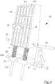
- the stake anchoring arrangement 1 comprises a wedge assembly, generally designated 10, see also figures 3 , 5-6 , which shows a wedge assembly 10 according to the preferred first embodiment of the present invention, and figure 4 , which shows an alternative embodiment of the wedge assembly 10 according to the preferred first embodiment of the present invention.
- the wedge assembly 10 is arranged to act between the front wall 5 of the socket 3 and the front wall of the stake 2 which is axially lowerable into the socket 3.
- the wedge assembly 10 comprises a catch 11, which is turnably arranged about a pivot 12, at least one spring member 13 and a wedge member 14, which is axially displaceable in relation to the socket 3 as will be described in more detail below.
- the wedge member 14 comprises a first surface 15 arranged to abut the front wall 5 of the socket 3 and a second surface 16 arranged to abut the front wall of the socket 2.
- the first surface 15 of the wedge member 14 incline in the same extent as the front wall 5 of the socket 3, and the second surface 16 of the wedge member 14 is generally parallel to the front wall of the stake 2.
- the front wall 16 of the wedge member 14 presents a complementary shape in relation to the front wall of the stake 2 and is in the shown embodiment concavely arc shaped seen in the horizontal plane.
- the wedge assembly 10 also comprises a base plate 17, in which the pivot 12 of the catch 11 is arranged.
- the first surface 15 of the wedge member 14 may preferably present at least one recess (15a, for instance in the shape of axially extending and/or transversally extending groves, see figure 4 .
- the object of said recess 15a is to decrease the abutment surface between the wedge member 14 and the front wall 5 of the socket 3, and preferably also to scrape off possible litter from the front wall 5 of the socket 3 and accumulate in the groove 15a in order to avoid that the function of the wedge member 14 is affected. It shall be pointed out that in the embodiment in which the wedge member 14 comprises such grooves 15a, they shall preferably end at a distance from the upper edge of the first surface 15 of the wedge member 14, such that litter shall not find its way down between the wedge member 14 and the socket 3.
- the catch 11 comprises means for engagement with the wedge member 14, which wedge engagement means in the shown embodiment is constituted by a lower groove 18a arranged in the catch 11.
- the lower groove 18a is preferably arc shaped.
- the wedge member 14 comprises in its turn means for engagement with the catch 11, which catch engagement means in the shown embodiment is constituted by at least one transverse rod 19, which extends transverse a recess 20 in the wedge member 14 and at the same time is in engagement with the lower groove 18a of the catch 11 that is movably housed in the recess 20.
- the lower groove 18a is arranged through the catch 11 and the transverse rod 19 extends through the lower groove 18a and the recess, the transverse rod 19 being connected to the wedge member 14 on each side of the recess 20.
- the wedge member 14 in the shown embodiment comprises at least one snap member 21, which in the shown embodiment is constituted by a cartridge shaped holder having a spring biased ball and which is arranged to cooperate with the lower groove 18a of the catch 11 and thus constitutes yet another catch engagement means.
- the spring member 13 is arranged to displace the wedge member 14 in the axial direction upwards in relation to the socket 3.
- the spring member 13 is constituted by a helical spring arranged in a bore 22 in the wedge member 14, which bore 22 preferably is arranged in parallel with the first surface 15 of the wedge member 14.
- the bore 22 shall preferably have a significant length such that the effective force of the spring member 13 shall not change in considerable extent concurrently with the axial displacement of the wedge member 14 and the pressed spring member 13 is elongated.
- the base plate 17 preferably comprises a seat 23 for the spring member 13 in order to prevent displacement in the radial direction of the lower end of the spring member 13.
- the wedge assembly 10 comprises a guide rod 13a for the respective spring member 13, which guide rod 13a is arranged in the spring member 13 and prevents the spring member 13 from bulging in the transverse direction and thereby a correct function of the wedge assembly 10 is secured.
- the guide rod 13a is preferably connected to the base plate 17, for instance by means of stop screws 13b, which entail that the guide rod 13a also constitute a guide for the axial movement of the wedge member 14. It shall be pointed out that the guide rod 13a also may be connected to the wedge member 14, or be loosely arranged in the spring member 13.
- the wedge assembly 10 is arranged to take a primed condition, awaiting a stake 2 being lowered into and anchored in the socket 3, and an activated condition when the stake 2 is anchored in the socket 3.
- the wedge assembly 10 is in the primed condition at the same time as a stake 2 is lowered into the socket 3.
- the wedge member 14 comprises a threaded hole 24, which mouth in the first surface 15 of the wedge member 14 and in which a screw 25 is screwed into.
- the head of the screw 25 is located at the opposite side of the front wall 5 of the socket 3 in relation to the wedge member 14 and the stem of the screw 25 runs freely through an axially extending groove 26 arranged in the front wall 5 of the socket 3.
- the wedge assembly 10 is prevented from falling against the back wall 6 of the socket 3 when the stake 2 is not in the lowered state, at the same time as the wedge member 14 is allowed to be displaced in the axial direction.
- the groove 26 has a so called keyhole shape in which the groove 26 in its upper end presents a larger diameter than the head of the screw 25, in order to admit that the screw 25 can be screwed into the hole 24 in the wedge member 24 and thereafter the wedge assembly 10 is applied in the socket 3 by running the screw 25 through and engaging the groove 26.
- the wedge member 14 In the primed condition of the wedge assembly 10 the wedge member 14 is located in a lower position by pressing the wedge member 14 down towards the base plate 17 against the action of the spring member 13, which thereby is in a biased position acting to displace the wedge member 14 from the lower position to an upper position in which the stake 2 is secured.
- the catch 11 Upon pressing of the wedge member 14 towards the base plate 17 the catch 11 is in an activated position (see figures 6 and 7 ) and the transverse rod 19 of the wedge member 14 runs in an upper groove 18b of the catch 11, which upper groove 18b is generally straight and arranged generally parallel to the first surface 15 of the wedge member 14.
- the transverse rod 19 reaches the lower end of the upper groove 18b the wedge member 14 has reached its lower position.
- the catch 11 for instance by hand, can be turned to a primed position (see figure 1 ), during which turning the transverse rod 19 runs in the lower arc shaped groove 18a of the catch 11, wherein the arc centre of the groove 18a generally coincide with the pivot 12 of the catch 11. It shall be pointed out that the lower groove 18a of the catch 11 and the upper groove 18b of the catch 11 thus overlap or join each other.
- the catch 11 is arranged to when in the primed position retain the wedge member 14 in the lower position by having the wedge engaging means 18a of the catch 11 in engagement with the catch engaging means 19 of the wedge member 14 when the catch 11 is in the primed position, which prevents the wedge member 14 from being displaced from the lower position to the upper position.
- the arc centre of the lower groove 18a is offset in relation to the pivot 12 such that the wedge member 14, under the action of the spring member 13, is displaced a short distance away from the base plate 17 at the same time as the catch 11 turns from the activated position to the primed position.
- the wedge member 14 also comprises said snap member 21, the snap member 21 shall be located at such a place in the recess 20 of the wedge member 14 that it will engage the lower groove 18a and/or the upper groove 18b of the catch 11 when the catch 11 is turned to the primed position, the snap member 21 retaining the catch 11 in the primed position. It shall be pointed out that the wedge assembly 10 can be brought to the primed condition before as well as after it has been applied to the socket 3. Upon lowering of the stake 2 into the socket 3 the wedge member 14 is located at a distance from the front wall of the stake 2.
- the catch 11 also comprises a shoulder 27 arranged to engage the stake 2 upon lowering of the stake 2 into the socket 3.
- the shoulder 27 is arranged to engage the lower end of the stake 2.
- the stake 2 is lowered and has just come into contact with the shoulder 27 of the catch 11.
- the catch 11 is forced to turn from the primed position to the activated position, see figure 7 , whereupon the wedge member 14 is set in a disengaged condition.
- the lower end of the stake 2 abuts the bottom of the socket 3 when the catch 11 is in the activated position.
- the catch 11 preferably also comprises a means for engagement with the stake 2.
- the stake engagement means of the catch 11 is arranged to prevent the stake from being pulled out of the socket 3 when the wedge member 14 is displaced from the lower position. This may for instance take place if oil, leaf, dirt, etc., has attached to one of more abutment surfaces between the socket 3, the stake 2 and the wedge member 14.
- the stake engaging means of the catch 11 is constituted by a claw 28 arranged above the shoulder 27 of the catch 11.
- the claw 28 of the catch 11 is arranged to engage a recess 29 in the front wall of the stake 2 when the catch 11 is in the activated position, and arranged to be disengaged from said recess 29 when the catch 11 is in the primed position.
- the transverse rod 19 of the wedge member 14 is located in the upper groove 18b of the catch 11, the catch 11 being prevented from turning from the activated position and thereby the claw 28 of the catch 11 retains the stake 2 in the socket 3.
- the claw of the catch also has the function of reprime the wedge assembly 10 upon removal of the stake 2 from the socket 3.
- the catch 11 When the wedge member 14 is pressed down to the lower position by applying a force to the upper surface 30 of the wedge member 14 the catch 11 is allowed to turn from the activated position to the primed position, at the same time as the stake 2 is no longer clamped between the wedge member 14 and the back wall 6 of the socket 3. Upon subsequent removal of the stake 2 the recess 29 of the stake 2 will lift the claw 28 of the catch 11 whereupon the catch 11 will turn from the activated position to the primed position. Thereafter the pressure applied to the upper surface 30 of the wedge member 14 can be removed and the wedge assembly 10 is primed and ready for the next anchoring of a stake 2 in the socket 3. In a not shown alternative and/or supplementary embodiment the catch 11 is turned from the activated position to the primed position by means of a spring in connection with the stake 2 being removed from the socket 3.
- FIG 8 in which is shown a second embodiment of the inventive stake anchoring arrangement 1.
- the stake 2 and the socket 3 are more or less unchanged, and the cooperation between the socket 3, the stake 2 and the wedge member 14 is unchanged, and only differences in relation to the above described first embodiment of the stake anchoring arrangement 1 will be described below.
- the wedge assembly 10 comprises a catch 11, a spring member 13 and a wedge member 14.
- the catch 11 is rotatably arranged about a pivot 12 that in this embodiment is connected to the socket 3, and the spring member 13 acts between the wedge member 14 and the bottom 4 of the socket 3, which entail that the wedge assembly 10 cannot be removed from the socket 3 as a single unit, instead the wedge assembly 10 most be primed when arranged in the socket 3.
- the wedge engaging means of the catch 11 is in this embodiment constituted by a finger 31 that, when the wedge member 14 is in the lower position and the catch is in the primed position, is in engagement with the catch engaging means of the wedge member 14 that in this embodiment is constituted by a protrusion 32.
- the wedge assembly 10 is then in the primed condition (not shown).
- the catch 11 preferably comprises a stake engaging means in the shape of a claw 28 arranged above the shoulder 27 of the catch 11.
- the claw 28 of the catch 11 is arranged to engage a recess 29 in the front wall of the stake 2 when the catch 11 is in the activated position, and arranged to be disengaged from said recess 29 when the catch 11 is in the primed position.
- the protrusion 32 of the wedge member 14 is located aligned with the finger 31 of the catch 11, the catch 11 being prevented from turning from the activated position and thereby the claw 28 of the catch 11 retains the stake 2 in the socket 3.
- the claw 28 of the catch 11 also in this second embodiment has the function of repriming the wedge assembly 10 upon removal of the stake 2 from the socket 3, in the same way as in the first embodiment.
- the advantage of the shown second embodiment of the stake anchoring arrangement 1 is that it comprises fewer parts than the first embodiment.
- the advantage with the first embodiment of the stake anchoring arrangement 1 is that it can be removed from the socket 3 as a single unit and be primed outside the socket 3.
- both embodiments present easy anchoring of a stake 2 in a socket 3.
Landscapes
- Engineering & Computer Science (AREA)
- Transportation (AREA)
- Mechanical Engineering (AREA)
- Chemical & Material Sciences (AREA)
- Combustion & Propulsion (AREA)
- Joining Of Building Structures In Genera (AREA)
- Piles And Underground Anchors (AREA)
- Buckles (AREA)
Description
- The present invention relates in general to a disengageable anchoring of a load shifting protection in a load carrying structure of a truck, a railway wagon or any other craft. In particular the present invention relates to a stake anchoring arrangement for the anchoring of a stake in a load carrying structure, the stake anchoring arrangement comprising an upwardly open socket which is arranged to be connected to the load carrying structure and which comprises a front wall and a back wall opposite the front wall, furthermore the stake anchoring arrangement comprises a wedge assembly that is arranged to act between the front wall of the socket and a stake axially lowerable into the socket. It shall be pointed out that even thus within the technical field recognized term "stake" for sake of simplicity has been used in the claims as well as in the description, it shall be realized that also other types as well as other terms of load shifting protection are included, such as supports, posts, limb anchoring posts, etc.
- During transportation of cargo on any conceivable vehicle/craft, such as trucks, trailers, railway wagons, ships, etc., there is almost always a need to secure the cargo from being shifted in the longitudinal direction and/or the transverse direction of the vehicle. An elucidating example, which shall not be considered limiting for the present invention, is a truck having a flat loading platform. The truck shall at one occasion transport timber, the truck driver placing a row of a number of upright stakes along each of the two longitudinal edges of the loading platform. Thereafter the timber is placed on the loading platform oriented in the longitudinal direction of the truck, the stakes acting as load shifting protection in the transverse direction of the truck. After the timber has been unloaded from the truck it shall transport big laying cement culverts, the truck driver placing stakes in front of, behind and on each side of the cement culverts, thereby the stakes acts as load shifting protection in the longitudinal direction and the transverse direction of the truck. Thereafter the truck shall transport big upright boards, the truck driver placing two longitudinal rows of stakes in the middle of the loading platform. The boards are placed between the two adjacent rows of stakes, the stakes acting as load shifting protection in the transverse direction of the truck. It is readily realized that the loading platform must have a stake anchoring arrangement that is flexible in such a way that the driver must be able to adapt the appearance/configuration of the loading platform in an easy way out on the roads without the need of work shop tools. Theoretically a loading platform having a large number of round sockets in which round stakes easily can be lowered into and removed from be a solution, however, there are both laws stating and demands from the drivers that the stakes shall be secured/locked to the load carrying structure such that the stakes cannot jump out of the sockets during transportation, or rattle or shake when without load.
- Flexible, disengageable anchoring of stakes in stake anchoring arrangements can be divided into two main groups, a first group using a locking mechanism arranged in the stake and a second group using a locking mechanism arranged in or at the socket.
- Example of disengageable anchoring in stake anchoring arrangements belonging to the first group are shown in
EP0244383 andSE451987 - Example of disengageable anchoring of stake anchoring arrangements belonging to the second group are shown in
SE451009 WO93/24344 SE405235 SE463759 - The present invention aims at obviating the above-mentioned disadvantages and failings of previously known stake anchoring arrangements and at providing an improved stake anchoring arrangement. A primary object of the invention is to provide an improved stake anchoring arrangement of the initially defined type, which admits automatic, disengageable anchoring of the stake in the socket during lowering of the stake therein, which in other words have in view that no tools are needed in order to anchor the stake in the socket.
- It is another object of the present invention to provide a stake anchoring arrangement, that does not need any specific procedures in order to anchor the stake in the socket.
- It is another object of the present invention to provide a stake anchoring arrangement that prevents the stake to rattle or shake in the socket.
- It is yet another object of the present invention to provide a stake anchoring arrangement that in connection with removal of the stake is primed to the next lowering/anchoring of a stake.
- According to the invention at least the primary object of the invention is attained by the initially defined stake anchoring arrangement, which is characterized in that the front wall incline in the direction of the back wall, and in that the wedge assembly comprises a catch, a spring member and a wedge member, the catch being turnably arranged about a pivot from a primed position to an activated position under the action of the axially lowerable stake, thereto the catch is arranged when in the primed position to maintain the wedge member in a lower position and when in the activated position set the wedge member in a disengaged condition, the wedge member when in the disengaged condition being axially displaceable from the lower position to an upper position under the action of the spring member in order to wedge said axially lowerable stake between the wedge member and the back wall of the socket.
- Thus the present invention is based on the insight that by using the stake to activate the locking mechanism, which in its turn locks the stake the more the stake rattle and shake, an easy handling of the stakes is obtained without the need of special tools or procedures.
- Preferred embodiments of the present invention are further defined in the independent claims.
- Preferably the catch comprises a shoulder arranged to be activated by the axially lowerable stake and means for engagement with the wedge member. Thereto the wedge member comprises a first surface arranged to abut the front wall of the socket, a second surface arranged to abut the axially lowerable stake and means for engagement with the catch. Which entail that the stake upon lowering thereof will activate the wedge assembly, whereupon the wedge member will lock the stake in the socket.
- According to a preferred embodiment the wedge assembly is arranged to take a primed condition, in which the wedge member is in the lower position, the catch is in the primed position, and in which the wedge member engagement means of the catch is in engagement with the catch engagement means of the wedge member and the spring member is in a biased position acting to displace the wedge member from the lower position to the upper position, and take an activated condition, in which the shoulder of the catch is activated by the axially lowerable stake whereupon the catch is turned to the activated position, the wedge member engagement means of the catch is disengaged from the catch engagement means of the wedge member and the wedge member is displaced to the upper position under the action of the spring member in order to wedge the axially lowerable stake between the second surface of the wedge member and the back wall of the socket.
- In yet another preferred embodiment the wedge member engagement means of the catch is constituted by a lower groove, and the catch engagement means of the wedge member is constituted by a pin arranged transverse said grove, which is displaceable in relation to said pin. This entail that the catch and the wedge member are connected to each other and hangs together as a single unit.
- Preferably the catch engagement means of the wedge member is arranged to prevent the catch from turning from the activated position to the primed position when the wedge member is displaced from the lower position.
- Preferably the catch also comprises means for engagement with the axially lowerable stake, the stake engagement means of the catch being arranged to maintain said stake in the lowered position when the catch is in the activated position. This entail that even thus the wedge member by any reason cannot on its own succeed to retain the stake in the socket the stake is prevented from being pulled out of the socket by means of the catch.
- Preferably the wedge assembly also comprises a base plate, the pivot being supported by said base plate, and the spring member is arranged between the base plate and the wedge member. This entail that the wedge assembly is constituted by a connected unit that can be removed from the socket.
- Further advantages with and features of the invention will be apparent from the other independent claims as well as from the following detailed description of preferred embodiments.
- A more complete understanding of abovementioned and other features and advantages of the present invention will be apparent from the following detailed description of preferred embodiments in conjunction with the enclosed drawings, wherein:
- Fig. 1
- is a cutaway side view of a first embodiment of the present stake anchoring arrangement in the primed condition,
- Fig. 2
- is a cutaway side view from above of the stake anchoring arrangement according to the first embodiment,
- Fig. 3
- is a perspective exploded view of the stake anchoring arrangement according to the first embodiment of the stake anchoring arrangement,
- Fig. 4
- is a perspective exploded view of an alternative embodiment of the stake anchoring arrangement according to the first embodiment of the stake anchoring arrangement,
- Fig. 5
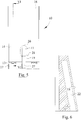
- is a side view of the stake anchoring arrangement according to
figure 3 , - Fig. 6
- is a cutaway side view of the wedge member taken along line VI-VI in
figure 5 , - Fig. 7
- is a cutaway side view of the stake anchoring arrangement shown in
figure 1 in a state between the primed and the activated condition, - Fig. 8
- is a cutaway side view of the stake anchoring arrangement shown in
figure 1 in the activated condition, and - Fig. 9
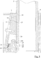
- is a cutaway side view of a second embodiment of the present stake anchoring arrangement in the activated condition.
- The present invention relates in general to a disengageable anchoring of a load shifting protection in a load carrying structure of a craft, such as the load carrying frame of a vehicle or the load carrying deck of a ship. The load carrying structure can be constituted by for instance a loading platform or a bolster of a bunk (not shown).
- Reference is initially made to
figure 1 , in which is shown a first embodiment of the inventive stake anchoring arrangement, generally designated 1, for the anchoring of astake 2 in a load carrying structure (not shown), as well as tofigure 2 , in whish is shown a cutaway view from above of the stake anchoring arrangement according tofigure 1 . Thestake 2 is preferable tubular and made out of aluminum, high strength steel or any other suitable material in order to be as light as possible. Thestake anchoring arrangement 1 comprises an upwardly open socket, generally designated 3, comprising a circumferentially extending wall and abottom 4, which together defines a seat for theaxially lowerable stake 2. When thestake 2 is in the anchored state in thesocket 3 at least a part of the lower end of thestake 2 shall preferably abut and be supported by thebottom 4 of thesocket 3. The circumferentially extending wall of thesocket 3 comprises afront wall 5 and aback wall 6 opposite to the front wall, as well as opposite side walls 7 which extends between thefront wall 5 and theback wall 6. Thesocket 3 is arranged to be connected, fixedly or releasably, to the load carrying structure in any suitable way. Preferably thesocket 3 is arranged in such a way that itsupper surface 8 is arranged on the same level as the load carrying surface of the load carrying structure. Thebottom 4 of thesocket 3 preferably present one or more throughholes 9, such that litter, snow, rain and such does not risk to be accumulated in thesocket 3, which otherwise would prevent correct lowering of thestake 2 in thesocket 3. Thereto at least the upper part of thefront wall 5 of thesocket 3 shall incline in the direction towards theback wall 6, in order to present a wedge surface. The feature that thefront wall 5 shall incline in the direction towards theback wall 6, thus also includes that only the upper part of thefront wall 5 incline in the direction backwards. The inclination angle α shall be bigger than 5 degrees preferably bigger than 10 degrees, at the same time as the inclination angle α of thefront wall 5 shall be less than 30 degrees preferably less than 15 degrees. Theback wall 6 of thesocket 3 shall in its turn be generally parallel to the back wall of thestake 2 and preferably theback wall 6 of thesocket 3 correspond to the configuration of thestake 2 in the area of the lower end thereof, and is in the shown embodiment concavely arch shaped seen in the horizontal plane. It shall be pointed out that when thestake 2 is lowered into thesocket 3 and its front wall is loaded in the direction from thefront wall 5 of thesocket 3 towards theback wall 6 it is important that the back wall of thestake 2 abut, direct or indirect, theback wall 6 of thesocket 3 in the area of the upper end thereof. In the shown embodiment theback wall 6 has a generally vertical extension. - Further, the
stake anchoring arrangement 1 comprises a wedge assembly, generally designated 10, see alsofigures 3 ,5-6 , which shows awedge assembly 10 according to the preferred first embodiment of the present invention, andfigure 4 , which shows an alternative embodiment of thewedge assembly 10 according to the preferred first embodiment of the present invention. Thewedge assembly 10 is arranged to act between thefront wall 5 of thesocket 3 and the front wall of thestake 2 which is axially lowerable into thesocket 3. - According to the invention the
wedge assembly 10 comprises acatch 11, which is turnably arranged about apivot 12, at least onespring member 13 and awedge member 14, which is axially displaceable in relation to thesocket 3 as will be described in more detail below. - The
wedge member 14 comprises afirst surface 15 arranged to abut thefront wall 5 of thesocket 3 and asecond surface 16 arranged to abut the front wall of thesocket 2. Thefirst surface 15 of thewedge member 14 incline in the same extent as thefront wall 5 of thesocket 3, and thesecond surface 16 of thewedge member 14 is generally parallel to the front wall of thestake 2. Furthermore, thefront wall 16 of thewedge member 14 presents a complementary shape in relation to the front wall of thestake 2 and is in the shown embodiment concavely arc shaped seen in the horizontal plane. It shall be pointed out that the shown concavity of theback wall 6 of thesocket 3 and thesecond surface 16 of thewedge member 14 acts centering and aligns thestake 2, which does not necessarily need to be arranged to abut the side walls 7 of thesocket 3. In the shown first embodiment thewedge assembly 10 also comprises abase plate 17, in which thepivot 12 of thecatch 11 is arranged. Thefirst surface 15 of thewedge member 14 may preferably present at least one recess (15a, for instance in the shape of axially extending and/or transversally extending groves, seefigure 4 . The object of saidrecess 15a is to decrease the abutment surface between thewedge member 14 and thefront wall 5 of thesocket 3, and preferably also to scrape off possible litter from thefront wall 5 of thesocket 3 and accumulate in thegroove 15a in order to avoid that the function of thewedge member 14 is affected. It shall be pointed out that in the embodiment in which thewedge member 14 comprisessuch grooves 15a, they shall preferably end at a distance from the upper edge of thefirst surface 15 of thewedge member 14, such that litter shall not find its way down between thewedge member 14 and thesocket 3. - The
catch 11 comprises means for engagement with thewedge member 14, which wedge engagement means in the shown embodiment is constituted by alower groove 18a arranged in thecatch 11. Thelower groove 18a is preferably arc shaped. Thewedge member 14 comprises in its turn means for engagement with thecatch 11, which catch engagement means in the shown embodiment is constituted by at least onetransverse rod 19, which extends transverse arecess 20 in thewedge member 14 and at the same time is in engagement with thelower groove 18a of thecatch 11 that is movably housed in therecess 20. Preferably thelower groove 18a is arranged through thecatch 11 and thetransverse rod 19 extends through thelower groove 18a and the recess, thetransverse rod 19 being connected to thewedge member 14 on each side of therecess 20. Furthermore, thewedge member 14 in the shown embodiment comprises at least onesnap member 21, which in the shown embodiment is constituted by a cartridge shaped holder having a spring biased ball and which is arranged to cooperate with thelower groove 18a of thecatch 11 and thus constitutes yet another catch engagement means. - The
spring member 13 is arranged to displace thewedge member 14 in the axial direction upwards in relation to thesocket 3. In the shown embodiment thespring member 13 is constituted by a helical spring arranged in abore 22 in thewedge member 14, which bore 22 preferably is arranged in parallel with thefirst surface 15 of thewedge member 14. Thebore 22 shall preferably have a significant length such that the effective force of thespring member 13 shall not change in considerable extent concurrently with the axial displacement of thewedge member 14 and the pressedspring member 13 is elongated. Furthermore, thebase plate 17 preferably comprises aseat 23 for thespring member 13 in order to prevent displacement in the radial direction of the lower end of thespring member 13. Thereto it is preferred that thewedge assembly 10 comprises aguide rod 13a for therespective spring member 13, which guiderod 13a is arranged in thespring member 13 and prevents thespring member 13 from bulging in the transverse direction and thereby a correct function of thewedge assembly 10 is secured. Theguide rod 13a is preferably connected to thebase plate 17, for instance by means of stop screws 13b, which entail that theguide rod 13a also constitute a guide for the axial movement of thewedge member 14. It shall be pointed out that theguide rod 13a also may be connected to thewedge member 14, or be loosely arranged in thespring member 13. - The
wedge assembly 10 is arranged to take a primed condition, awaiting astake 2 being lowered into and anchored in thesocket 3, and an activated condition when thestake 2 is anchored in thesocket 3. Reference is now made especially tofigures 1 ,6 and7 . - In
figure 1 thewedge assembly 10 is in the primed condition at the same time as astake 2 is lowered into thesocket 3. In order to prevent that thewedge assembly 10 from running the risk of falling and preventing correct lowering of thestake 2, thewedge member 14 comprises a threadedhole 24, which mouth in thefirst surface 15 of thewedge member 14 and in which ascrew 25 is screwed into. The head of thescrew 25 is located at the opposite side of thefront wall 5 of thesocket 3 in relation to thewedge member 14 and the stem of thescrew 25 runs freely through anaxially extending groove 26 arranged in thefront wall 5 of thesocket 3. Thus, thewedge assembly 10 is prevented from falling against theback wall 6 of thesocket 3 when thestake 2 is not in the lowered state, at the same time as thewedge member 14 is allowed to be displaced in the axial direction. Preferably thegroove 26 has a so called keyhole shape in which thegroove 26 in its upper end presents a larger diameter than the head of thescrew 25, in order to admit that thescrew 25 can be screwed into thehole 24 in thewedge member 24 and thereafter thewedge assembly 10 is applied in thesocket 3 by running thescrew 25 through and engaging thegroove 26. This entail also that one and thesame wedge assembly 10 may be used inseveral sockets 3, dependent on which socket of several sockets shall be used at the moment. - In the primed condition of the
wedge assembly 10 thewedge member 14 is located in a lower position by pressing thewedge member 14 down towards thebase plate 17 against the action of thespring member 13, which thereby is in a biased position acting to displace thewedge member 14 from the lower position to an upper position in which thestake 2 is secured. Upon pressing of thewedge member 14 towards thebase plate 17 thecatch 11 is in an activated position (seefigures 6 and7 ) and thetransverse rod 19 of thewedge member 14 runs in anupper groove 18b of thecatch 11, whichupper groove 18b is generally straight and arranged generally parallel to thefirst surface 15 of thewedge member 14. When thetransverse rod 19 reaches the lower end of theupper groove 18b thewedge member 14 has reached its lower position. Thereafter thecatch 11, for instance by hand, can be turned to a primed position (seefigure 1 ), during which turning thetransverse rod 19 runs in the lower arc shapedgroove 18a of thecatch 11, wherein the arc centre of thegroove 18a generally coincide with thepivot 12 of thecatch 11. It shall be pointed out that thelower groove 18a of thecatch 11 and theupper groove 18b of thecatch 11 thus overlap or join each other. Thus thecatch 11 is arranged to when in the primed position retain thewedge member 14 in the lower position by having the wedge engaging means 18a of thecatch 11 in engagement with thecatch engaging means 19 of thewedge member 14 when thecatch 11 is in the primed position, which prevents thewedge member 14 from being displaced from the lower position to the upper position. In an alternative not shown embodiment the arc centre of thelower groove 18a is offset in relation to thepivot 12 such that thewedge member 14, under the action of thespring member 13, is displaced a short distance away from thebase plate 17 at the same time as thecatch 11 turns from the activated position to the primed position. In the embodiment thewedge member 14 also comprises saidsnap member 21, thesnap member 21 shall be located at such a place in therecess 20 of thewedge member 14 that it will engage thelower groove 18a and/or theupper groove 18b of thecatch 11 when thecatch 11 is turned to the primed position, thesnap member 21 retaining thecatch 11 in the primed position. It shall be pointed out that thewedge assembly 10 can be brought to the primed condition before as well as after it has been applied to thesocket 3. Upon lowering of thestake 2 into thesocket 3 thewedge member 14 is located at a distance from the front wall of thestake 2. - The
catch 11 also comprises ashoulder 27 arranged to engage thestake 2 upon lowering of thestake 2 into thesocket 3. Preferably theshoulder 27 is arranged to engage the lower end of thestake 2. Infigure 1 thestake 2 is lowered and has just come into contact with theshoulder 27 of thecatch 11. Upon further lowering of thestake 2, by means if its inherent weight, thecatch 11 is forced to turn from the primed position to the activated position, seefigure 7 , whereupon thewedge member 14 is set in a disengaged condition. Preferably the lower end of thestake 2 abuts the bottom of thesocket 3 when thecatch 11 is in the activated position. Infigure 7 the wedge engaging means 18 of thecatch 11 has disengaged thecatch engaging means 19 of thewedge member 14 during the turn of thecatch 11 to the activated position. In the disengaged condition thewedge member 14 is axially displaceable from the lower position to the upper position. It shall be pointed out that thewedge member 14 cannot retain in the lower position when thecatch 11 is in the activated position, as is shown infigure 7 , insteadfigure 7 is only a snapshot of the lapse. - In
figure 8 thewedge member 14 has been displaced to the upper position under the action of thespring member 13. In the upper position thefirst surface 15 of thewedge member 14 abuts thefront wall 5 of thesocket 3 at the same time assecond surface 16 of thewedge member 14 abuts the front wall of thestake 2, in order to anchor/clamp theaxially lowerable stake 2 between thesecond surface 16 of thewedge member 14 and theback wall 6 of thesocket 3. It shall be pointed out that if thestake 2 moves thewedge member 14 will be displaced more and more upwards and thereby clamp thestake 2 harder towards thesocket 3. - In the shown first embodiment of the
stake anchoring arrangement 1 thecatch 11 preferably also comprises a means for engagement with thestake 2. The stake engagement means of thecatch 11 is arranged to prevent the stake from being pulled out of thesocket 3 when thewedge member 14 is displaced from the lower position. This may for instance take place if oil, leaf, dirt, etc., has attached to one of more abutment surfaces between thesocket 3, thestake 2 and thewedge member 14. In the shown first embodiment of thestake anchoring arrangement 1 the stake engaging means of thecatch 11 is constituted by aclaw 28 arranged above theshoulder 27 of thecatch 11. Theclaw 28 of thecatch 11 is arranged to engage arecess 29 in the front wall of thestake 2 when thecatch 11 is in the activated position, and arranged to be disengaged from saidrecess 29 when thecatch 11 is in the primed position. Thereto it shall be pointed out that when thewedge member 14 is displaced from the lower position thetransverse rod 19 of thewedge member 14 is located in theupper groove 18b of thecatch 11, thecatch 11 being prevented from turning from the activated position and thereby theclaw 28 of thecatch 11 retains thestake 2 in thesocket 3. Furthermore the claw of the catch also has the function of reprime thewedge assembly 10 upon removal of thestake 2 from thesocket 3. When thewedge member 14 is pressed down to the lower position by applying a force to theupper surface 30 of thewedge member 14 thecatch 11 is allowed to turn from the activated position to the primed position, at the same time as thestake 2 is no longer clamped between thewedge member 14 and theback wall 6 of thesocket 3. Upon subsequent removal of thestake 2 therecess 29 of thestake 2 will lift theclaw 28 of thecatch 11 whereupon thecatch 11 will turn from the activated position to the primed position. Thereafter the pressure applied to theupper surface 30 of thewedge member 14 can be removed and thewedge assembly 10 is primed and ready for the next anchoring of astake 2 in thesocket 3. In a not shown alternative and/or supplementary embodiment thecatch 11 is turned from the activated position to the primed position by means of a spring in connection with thestake 2 being removed from thesocket 3. - Reference is now made to
figure 8 , in which is shown a second embodiment of the inventivestake anchoring arrangement 1. Thestake 2 and thesocket 3 are more or less unchanged, and the cooperation between thesocket 3, thestake 2 and thewedge member 14 is unchanged, and only differences in relation to the above described first embodiment of thestake anchoring arrangement 1 will be described below. - The
wedge assembly 10 comprises acatch 11, aspring member 13 and awedge member 14. Thecatch 11 is rotatably arranged about apivot 12 that in this embodiment is connected to thesocket 3, and thespring member 13 acts between thewedge member 14 and thebottom 4 of thesocket 3, which entail that thewedge assembly 10 cannot be removed from thesocket 3 as a single unit, instead thewedge assembly 10 most be primed when arranged in thesocket 3. - The wedge engaging means of the
catch 11 is in this embodiment constituted by afinger 31 that, when thewedge member 14 is in the lower position and the catch is in the primed position, is in engagement with the catch engaging means of thewedge member 14 that in this embodiment is constituted by aprotrusion 32. Thewedge assembly 10 is then in the primed condition (not shown). - Upon lowering of the
stake 2 it will engage theshoulder 27 of thecatch 11, whereupon thecatch 11 turns from the primed position to the activated position. At the same time the wedge engaging means 31 of thecatch 11 disengage thecatch engaging means 32 of thewedge member 14, whereupon thewedge member 14 is set in a disengaged condition, whereupon thewedge member 14 under the action of thespring member 13 is displaced axially from the lower position to the upper position. - Also in the shown second embodiment of the
stake anchoring arrangement 1 thecatch 11 preferably comprises a stake engaging means in the shape of aclaw 28 arranged above theshoulder 27 of thecatch 11. Theclaw 28 of thecatch 11 is arranged to engage arecess 29 in the front wall of thestake 2 when thecatch 11 is in the activated position, and arranged to be disengaged from saidrecess 29 when thecatch 11 is in the primed position. Thereto it shall be pointed out that when thecatch 11 is in the activated position and thewedge member 14 is displaced from the lower position, theprotrusion 32 of thewedge member 14 is located aligned with thefinger 31 of thecatch 11, thecatch 11 being prevented from turning from the activated position and thereby theclaw 28 of thecatch 11 retains thestake 2 in thesocket 3. Thereto theclaw 28 of thecatch 11 also in this second embodiment has the function of repriming thewedge assembly 10 upon removal of thestake 2 from thesocket 3, in the same way as in the first embodiment. - The advantage of the shown second embodiment of the
stake anchoring arrangement 1 is that it comprises fewer parts than the first embodiment. The advantage with the first embodiment of thestake anchoring arrangement 1 is that it can be removed from thesocket 3 as a single unit and be primed outside thesocket 3. However, both embodiments present easy anchoring of astake 2 in asocket 3. - The invention is not limited only to the embodiments described above and shown in the drawings, which primarily have an illustrative and exemplifying purpose. This patent application is intended to cover all adjustments and variants of the preferred embodiments described herein, thus the present invention is defined by the wording of the appended claims. Thus, the equipment may be modified in all kinds of ways within the scope of the appended claims.
- It shall also be pointed out that all information about/concerning terms such as upper, lower, etc., shall be interpreted/read having the equipment oriented according to the figures, having the drawings oriented such that the references can be properly read. Thus, such terms only indicates mutual relations in the shown embodiments, which relations may be changed if the inventive equipment is provided with another structure/design.
- It shall also be pointed out that even thus it is not explicitly stated that features from a specific embodiment may be combined with features from another embodiment, the combination shall be considered obvious, if the combination is possible.
Claims (11)
- Stake anchoring arrangement for the anchoring of a stake (2) in a load carrying structure, comprising an upwardly open socket (3) which is arranged to be connected to the load carrying structure and which comprises a front wall (5) and a back wall (6) opposite the front wall (5), and a wedge assembly (10) that is arranged to act between the front wall (5) of the socket (3) and a stake (2) axially lowerable into the socket (3), characterized in that the front wall (5) inclines in the direction of the back wall (6), and in that the wedge assembly (10) comprises a catch (11), a spring member (13) and a wedge member (14), the catch (11) being turnably arranged about a pivot (12) from a primed position to an activated position under the action of the axially lowerable stake (2), thereto the catch (11) is arranged when in the primed position to maintain the wedge member (14) in a lower position and when in the activated position set the wedge member (14) in a disengaged condition, the wedge member (14) when in the disengaged condition being axially displaceable from the lower position to an upper position under the action of the spring member (13) in order to wedge said axially lowerable stake (2) between the wedge member (14) and the back wall (6) of the socket (3).
- Stake anchoring arrangement according to claim 1, characterized in that the catch (11) comprises a shoulder (27) arranged to be activated by the axially lowerable stake (2) and means (18a, 31) for engagement with the wedge member (14).
- Stake anchoring arrangement according to claim 2, characterized in that the wedge member (14) comprises a first surface (15) arranged to abut the front wall (5) of the socket (3), a second surface (16) arranged to abut the axially lowerable stake (2) and means (19, 32) for engagement with the catch (11).
- Stake anchoring arrangement according to claim 3, characterized in that the wedge assembly (10) is arranged to take a primed condition, in which the wedge member (14) is in the lower position, the catch (11) is in the primed position, and in which the wedge member engagement means (18a, 31) of the catch (11) is in engagement with the catch engagement means (19, 32) of the wedge member (14) and the spring member (13) is in a biased position acting to displace the wedge member (14) from the lower position to the upper position.
- Stake anchoring arrangement according to claim 3 or 4, characterized in that the wedge assembly (10) is arranged to take an activated condition, in which the shoulder (27) of the catch (11) is activated by the axially lowerable stake (2) whereupon the catch (11) is turned to the activated position, the wedge member engagement means (18a, 31) of the catch (11) is disengaged from the catch engagement means (19, 32) of the wedge member (14) and the wedge member (14) is displaced to the upper position under the action of the spring member (13) in order to wedge the axially lowerable stake (2) between the second surface (16) of the wedge member (14) and the back wall (6) of the socket (3).
- Stake anchoring arrangement according to any of claims 3-5, characterized in that the wedge member engagement means of the catch (11) is constituted by a lower groove (18a), and the catch engagement means of the wedge member (14) is constituted by a pin (19) arranged transverse said grove (18a), which is displaceable in relation to said pin (19).
- Stake anchoring arrangement according to any of claims 3-5, characterized in that the catch engagement means (19, 32) of the wedge member (14) is arranged to prevent the catch (11) from turning from the activated position to the primed position when the wedge member (14) is displaced from the lower position.
- Stake anchoring arrangement according any preceding claim, characterized in that the catch (11) also comprises means (28) for engagement with the axially lowerable stake (2), the stake engagement means (28) of the catch (11) being arranged to maintain said stake (2) in the lowered position when the catch (11) is in the activated position.
- Stake anchoring arrangement according any preceding claim, characterized in that the catch (11) also comprises a return means for returning the catch (11) from the activated position to the primed position when the wedge member (14) is in the lower position.
- Stake anchoring arrangement according any preceding claim, characterized in that the wedge assembly (10) also comprises a base plate (17), the pivot (12) being supported by said base plate (17).
- Stake anchoring arrangement according to claim 10, characterized in that the spring member (13) is arranged between the base plate (17) and the wedge member (14).
Applications Claiming Priority (2)
| Application Number | Priority Date | Filing Date | Title |
|---|---|---|---|
| SE1050633A SE1050633A1 (en) | 2010-06-18 | 2010-06-18 | Stake Anchoring Arrangements |
| PCT/SE2011/050738 WO2011159239A1 (en) | 2010-06-18 | 2011-06-15 | Stake anchoring arrangement |
Publications (3)
| Publication Number | Publication Date |
|---|---|
| EP2582544A1 EP2582544A1 (en) | 2013-04-24 |
| EP2582544A4 EP2582544A4 (en) | 2014-03-26 |
| EP2582544B1 true EP2582544B1 (en) | 2016-12-14 |
Family
ID=43939661
Family Applications (1)
| Application Number | Title | Priority Date | Filing Date |
|---|---|---|---|
| EP11796056.7A Active EP2582544B1 (en) | 2010-06-18 | 2011-06-15 | Stake anchoring arrangement |
Country Status (3)
| Country | Link |
|---|---|
| EP (1) | EP2582544B1 (en) |
| SE (1) | SE1050633A1 (en) |
| WO (1) | WO2011159239A1 (en) |
Cited By (1)
| Publication number | Priority date | Publication date | Assignee | Title |
|---|---|---|---|---|
| DE202018104000U1 (en) | 2018-07-11 | 2018-08-13 | Hülsmann Blechtechnologie GmbH & Co KG | Load-securing device |
Families Citing this family (2)
| Publication number | Priority date | Publication date | Assignee | Title |
|---|---|---|---|---|
| SE539166C2 (en) | 2015-08-10 | 2017-05-02 | Timbtech Ab | An arrangement for rigidly connecting a lower end of a vertical stake to a horizontal cross-beam |
| SE546376C2 (en) | 2021-04-23 | 2024-10-22 | Timbtech Int Ab | Stake arrangement for connecting a lower end of a vertical stake to a horizontal crossbeam, and method for producing a stake arrangement |
Family Cites Families (7)
| Publication number | Priority date | Publication date | Assignee | Title |
|---|---|---|---|---|
| SE306242B (en) * | 1964-06-16 | 1968-11-18 | P Andersson | |
| SE314696B (en) * | 1964-10-21 | 1969-09-15 | E Rickardsson | |
| SE451987B (en) * | 1978-09-21 | 1987-11-09 | Exte Fab | DEVICE FOR LOADING A LOADER LARGEABLE LOCATED POST |
| SE432396B (en) * | 1980-06-02 | 1984-04-02 | Exte Fab | Arrangement related to the anchoring of a post to a beam incorporated into the load-carrying cross member of a load-carrying vehicle |
| SE442848C (en) * | 1982-06-15 | 1986-06-02 | Laxo Mekan Ab | QUICK FIX FOR STOTTA |
| SE463759B (en) * | 1989-05-24 | 1991-01-21 | Exte Fab | DEVICE FOR UNLOCKABLE ANCHORING A POST BY A BANCH IN A VEHICLE'S TRUCK |
| SE470284B (en) * | 1992-05-22 | 1994-01-10 | Boerje Baumgarten | Load Bank Construction |
-
2010
- 2010-06-18 SE SE1050633A patent/SE1050633A1/en unknown
-
2011
- 2011-06-15 WO PCT/SE2011/050738 patent/WO2011159239A1/en not_active Ceased
- 2011-06-15 EP EP11796056.7A patent/EP2582544B1/en active Active
Non-Patent Citations (1)
| Title |
|---|
| None * |
Cited By (1)
| Publication number | Priority date | Publication date | Assignee | Title |
|---|---|---|---|---|
| DE202018104000U1 (en) | 2018-07-11 | 2018-08-13 | Hülsmann Blechtechnologie GmbH & Co KG | Load-securing device |
Also Published As
| Publication number | Publication date |
|---|---|
| SE534147C2 (en) | 2011-05-10 |
| SE1050633A1 (en) | 2011-05-10 |
| EP2582544A4 (en) | 2014-03-26 |
| WO2011159239A1 (en) | 2011-12-22 |
| EP2582544A1 (en) | 2013-04-24 |
Similar Documents
| Publication | Publication Date | Title |
|---|---|---|
| DE69022213T2 (en) | Wheel brake block for motor vehicle containers. | |
| DE68902720T2 (en) | LIFTING AND TRANSPORTING DEVICE. | |
| US10308163B2 (en) | Chain binder and method of operation | |
| DE69431516T2 (en) | VEHICLE WITH A U-SHAPED FRAME | |
| US8388287B2 (en) | Single point release mechanism for adjustable decking | |
| CA2987736A1 (en) | Rolling tarp enclosure system | |
| US9387789B2 (en) | Apparatus, system and method for dovetail locking mechanisms | |
| US11241922B2 (en) | Apparatus that facilitates moving a trailer | |
| EP2582544A1 (en) | Stake anchoring arrangement | |
| EP3130529B1 (en) | An arrangement for rigidly connecting a lower end of a vertical stake to a horizontal cross-beam | |
| US5421612A (en) | Trailer and tongue structure | |
| US20070224010A1 (en) | Locking device for securing loads | |
| US7534083B2 (en) | Trailer operable in lowered and raised transport positions | |
| CA2639371C (en) | Trailer for hauling tyres | |
| US20250222999A1 (en) | Pinless tilt deck trailer locking mechanism | |
| EP2703216B1 (en) | Commercial vehicle superstructure with load securing for double decker operation | |
| EP1733955B1 (en) | Device for securing of loads | |
| DE202009004719U1 (en) | Wheel chock for a motor vehicle | |
| CN119630558A (en) | Device for loading freight containers | |
| DE102009004090A1 (en) | Runge arrangement | |
| EP2548765A1 (en) | Securing device for securing exchangeable load containers on a skip lorry and skip lorry with such a securing device for holding exchangeable load containers | |
| DE19706493A1 (en) | Goods vehicle with additional upper load platforms | |
| CA2951809A1 (en) | Folding post for a vehicular load platform including biased positions | |
| CH695454A5 (en) | Device for storage, lifting or lowering of sea container has supports with loading hook, which laterally pass through lower container corner and lug, whereby device can take up container load and can deposit on footrest | |
| DE10113162C2 (en) | Transport platform with variable geometry for motorized two-wheelers, which is moved and locked in the actual means of transport via a tube system |
Legal Events
| Date | Code | Title | Description |
|---|---|---|---|
| PUAI | Public reference made under article 153(3) epc to a published international application that has entered the european phase |
Free format text: ORIGINAL CODE: 0009012 |
|
| 17P | Request for examination filed |
Effective date: 20121218 |
|
| AK | Designated contracting states |
Kind code of ref document: A1 Designated state(s): AL AT BE BG CH CY CZ DE DK EE ES FI FR GB GR HR HU IE IS IT LI LT LU LV MC MK MT NL NO PL PT RO RS SE SI SK SM TR |
|
| DAX | Request for extension of the european patent (deleted) | ||
| A4 | Supplementary search report drawn up and despatched |
Effective date: 20140226 |
|
| RIC1 | Information provided on ipc code assigned before grant |
Ipc: B60P 7/12 20060101AFI20140220BHEP Ipc: B62D 33/02 20060101ALI20140220BHEP |
|
| GRAP | Despatch of communication of intention to grant a patent |
Free format text: ORIGINAL CODE: EPIDOSNIGR1 |
|
| INTG | Intention to grant announced |
Effective date: 20160729 |
|
| GRAS | Grant fee paid |
Free format text: ORIGINAL CODE: EPIDOSNIGR3 |
|
| STAA | Information on the status of an ep patent application or granted ep patent |
Free format text: STATUS: GRANT OF PATENT IS INTENDED |
|
| GRAA | (expected) grant |
Free format text: ORIGINAL CODE: 0009210 |
|
| STAA | Information on the status of an ep patent application or granted ep patent |
Free format text: STATUS: THE PATENT HAS BEEN GRANTED |
|
| AK | Designated contracting states |
Kind code of ref document: B1 Designated state(s): AL AT BE BG CH CY CZ DE DK EE ES FI FR GB GR HR HU IE IS IT LI LT LU LV MC MK MT NL NO PL PT RO RS SE SI SK SM TR |
|
| REG | Reference to a national code |
Ref country code: GB Ref legal event code: FG4D |
|
| REG | Reference to a national code |
Ref country code: CH Ref legal event code: EP |
|
| REG | Reference to a national code |
Ref country code: IE Ref legal event code: FG4D |
|
| REG | Reference to a national code |
Ref country code: AT Ref legal event code: REF Ref document number: 853251 Country of ref document: AT Kind code of ref document: T Effective date: 20170115 |
|
| REG | Reference to a national code |
Ref country code: DE Ref legal event code: R096 Ref document number: 602011033454 Country of ref document: DE |
|
| PG25 | Lapsed in a contracting state [announced via postgrant information from national office to epo] |
Ref country code: LV Free format text: LAPSE BECAUSE OF FAILURE TO SUBMIT A TRANSLATION OF THE DESCRIPTION OR TO PAY THE FEE WITHIN THE PRESCRIBED TIME-LIMIT Effective date: 20161214 |
|
| REG | Reference to a national code |
Ref country code: LT Ref legal event code: MG4D |
|
| REG | Reference to a national code |
Ref country code: NL Ref legal event code: MP Effective date: 20161214 |
|
| PG25 | Lapsed in a contracting state [announced via postgrant information from national office to epo] |
Ref country code: SE Free format text: LAPSE BECAUSE OF FAILURE TO SUBMIT A TRANSLATION OF THE DESCRIPTION OR TO PAY THE FEE WITHIN THE PRESCRIBED TIME-LIMIT Effective date: 20161214 Ref country code: LT Free format text: LAPSE BECAUSE OF FAILURE TO SUBMIT A TRANSLATION OF THE DESCRIPTION OR TO PAY THE FEE WITHIN THE PRESCRIBED TIME-LIMIT Effective date: 20161214 Ref country code: GR Free format text: LAPSE BECAUSE OF FAILURE TO SUBMIT A TRANSLATION OF THE DESCRIPTION OR TO PAY THE FEE WITHIN THE PRESCRIBED TIME-LIMIT Effective date: 20170315 Ref country code: NO Free format text: LAPSE BECAUSE OF FAILURE TO SUBMIT A TRANSLATION OF THE DESCRIPTION OR TO PAY THE FEE WITHIN THE PRESCRIBED TIME-LIMIT Effective date: 20170314 |
|
| REG | Reference to a national code |
Ref country code: AT Ref legal event code: MK05 Ref document number: 853251 Country of ref document: AT Kind code of ref document: T Effective date: 20161214 |
|
| PG25 | Lapsed in a contracting state [announced via postgrant information from national office to epo] |
Ref country code: FI Free format text: LAPSE BECAUSE OF FAILURE TO SUBMIT A TRANSLATION OF THE DESCRIPTION OR TO PAY THE FEE WITHIN THE PRESCRIBED TIME-LIMIT Effective date: 20161214 Ref country code: RS Free format text: LAPSE BECAUSE OF FAILURE TO SUBMIT A TRANSLATION OF THE DESCRIPTION OR TO PAY THE FEE WITHIN THE PRESCRIBED TIME-LIMIT Effective date: 20161214 Ref country code: HR Free format text: LAPSE BECAUSE OF FAILURE TO SUBMIT A TRANSLATION OF THE DESCRIPTION OR TO PAY THE FEE WITHIN THE PRESCRIBED TIME-LIMIT Effective date: 20161214 |
|
| PG25 | Lapsed in a contracting state [announced via postgrant information from national office to epo] |
Ref country code: NL Free format text: LAPSE BECAUSE OF FAILURE TO SUBMIT A TRANSLATION OF THE DESCRIPTION OR TO PAY THE FEE WITHIN THE PRESCRIBED TIME-LIMIT Effective date: 20161214 |
|
| PG25 | Lapsed in a contracting state [announced via postgrant information from national office to epo] |
Ref country code: IS Free format text: LAPSE BECAUSE OF FAILURE TO SUBMIT A TRANSLATION OF THE DESCRIPTION OR TO PAY THE FEE WITHIN THE PRESCRIBED TIME-LIMIT Effective date: 20170414 Ref country code: EE Free format text: LAPSE BECAUSE OF FAILURE TO SUBMIT A TRANSLATION OF THE DESCRIPTION OR TO PAY THE FEE WITHIN THE PRESCRIBED TIME-LIMIT Effective date: 20161214 Ref country code: CZ Free format text: LAPSE BECAUSE OF FAILURE TO SUBMIT A TRANSLATION OF THE DESCRIPTION OR TO PAY THE FEE WITHIN THE PRESCRIBED TIME-LIMIT Effective date: 20161214 Ref country code: SK Free format text: LAPSE BECAUSE OF FAILURE TO SUBMIT A TRANSLATION OF THE DESCRIPTION OR TO PAY THE FEE WITHIN THE PRESCRIBED TIME-LIMIT Effective date: 20161214 Ref country code: RO Free format text: LAPSE BECAUSE OF FAILURE TO SUBMIT A TRANSLATION OF THE DESCRIPTION OR TO PAY THE FEE WITHIN THE PRESCRIBED TIME-LIMIT Effective date: 20161214 |
|
| PG25 | Lapsed in a contracting state [announced via postgrant information from national office to epo] |
Ref country code: BG Free format text: LAPSE BECAUSE OF FAILURE TO SUBMIT A TRANSLATION OF THE DESCRIPTION OR TO PAY THE FEE WITHIN THE PRESCRIBED TIME-LIMIT Effective date: 20170314 Ref country code: IT Free format text: LAPSE BECAUSE OF FAILURE TO SUBMIT A TRANSLATION OF THE DESCRIPTION OR TO PAY THE FEE WITHIN THE PRESCRIBED TIME-LIMIT Effective date: 20161214 Ref country code: BE Free format text: LAPSE BECAUSE OF FAILURE TO SUBMIT A TRANSLATION OF THE DESCRIPTION OR TO PAY THE FEE WITHIN THE PRESCRIBED TIME-LIMIT Effective date: 20161214 Ref country code: PT Free format text: LAPSE BECAUSE OF FAILURE TO SUBMIT A TRANSLATION OF THE DESCRIPTION OR TO PAY THE FEE WITHIN THE PRESCRIBED TIME-LIMIT Effective date: 20170414 Ref country code: PL Free format text: LAPSE BECAUSE OF FAILURE TO SUBMIT A TRANSLATION OF THE DESCRIPTION OR TO PAY THE FEE WITHIN THE PRESCRIBED TIME-LIMIT Effective date: 20161214 Ref country code: AT Free format text: LAPSE BECAUSE OF FAILURE TO SUBMIT A TRANSLATION OF THE DESCRIPTION OR TO PAY THE FEE WITHIN THE PRESCRIBED TIME-LIMIT Effective date: 20161214 Ref country code: SM Free format text: LAPSE BECAUSE OF FAILURE TO SUBMIT A TRANSLATION OF THE DESCRIPTION OR TO PAY THE FEE WITHIN THE PRESCRIBED TIME-LIMIT Effective date: 20161214 Ref country code: ES Free format text: LAPSE BECAUSE OF FAILURE TO SUBMIT A TRANSLATION OF THE DESCRIPTION OR TO PAY THE FEE WITHIN THE PRESCRIBED TIME-LIMIT Effective date: 20161214 |
|
| REG | Reference to a national code |
Ref country code: DE Ref legal event code: R097 Ref document number: 602011033454 Country of ref document: DE |
|
| PLBE | No opposition filed within time limit |
Free format text: ORIGINAL CODE: 0009261 |
|
| STAA | Information on the status of an ep patent application or granted ep patent |
Free format text: STATUS: NO OPPOSITION FILED WITHIN TIME LIMIT |
|
| 26N | No opposition filed |
Effective date: 20170915 |
|
| PG25 | Lapsed in a contracting state [announced via postgrant information from national office to epo] |
Ref country code: DK Free format text: LAPSE BECAUSE OF FAILURE TO SUBMIT A TRANSLATION OF THE DESCRIPTION OR TO PAY THE FEE WITHIN THE PRESCRIBED TIME-LIMIT Effective date: 20161214 |
|
| PG25 | Lapsed in a contracting state [announced via postgrant information from national office to epo] |
Ref country code: MC Free format text: LAPSE BECAUSE OF FAILURE TO SUBMIT A TRANSLATION OF THE DESCRIPTION OR TO PAY THE FEE WITHIN THE PRESCRIBED TIME-LIMIT Effective date: 20161214 |
|
| REG | Reference to a national code |
Ref country code: CH Ref legal event code: PL |
|
| GBPC | Gb: european patent ceased through non-payment of renewal fee |
Effective date: 20170615 |
|
| PG25 | Lapsed in a contracting state [announced via postgrant information from national office to epo] |
Ref country code: SI Free format text: LAPSE BECAUSE OF FAILURE TO SUBMIT A TRANSLATION OF THE DESCRIPTION OR TO PAY THE FEE WITHIN THE PRESCRIBED TIME-LIMIT Effective date: 20161214 |
|
| REG | Reference to a national code |
Ref country code: IE Ref legal event code: MM4A |
|
| REG | Reference to a national code |
Ref country code: FR Ref legal event code: ST Effective date: 20180228 |
|
| PG25 | Lapsed in a contracting state [announced via postgrant information from national office to epo] |
Ref country code: LU Free format text: LAPSE BECAUSE OF NON-PAYMENT OF DUE FEES Effective date: 20170615 Ref country code: CH Free format text: LAPSE BECAUSE OF NON-PAYMENT OF DUE FEES Effective date: 20170630 Ref country code: LI Free format text: LAPSE BECAUSE OF NON-PAYMENT OF DUE FEES Effective date: 20170630 Ref country code: GB Free format text: LAPSE BECAUSE OF NON-PAYMENT OF DUE FEES Effective date: 20170615 Ref country code: IE Free format text: LAPSE BECAUSE OF NON-PAYMENT OF DUE FEES Effective date: 20170615 |
|
| PG25 | Lapsed in a contracting state [announced via postgrant information from national office to epo] |
Ref country code: FR Free format text: LAPSE BECAUSE OF NON-PAYMENT OF DUE FEES Effective date: 20170630 |
|
| PG25 | Lapsed in a contracting state [announced via postgrant information from national office to epo] |
Ref country code: MT Free format text: LAPSE BECAUSE OF NON-PAYMENT OF DUE FEES Effective date: 20170615 |
|
| PG25 | Lapsed in a contracting state [announced via postgrant information from national office to epo] |
Ref country code: HU Free format text: LAPSE BECAUSE OF FAILURE TO SUBMIT A TRANSLATION OF THE DESCRIPTION OR TO PAY THE FEE WITHIN THE PRESCRIBED TIME-LIMIT; INVALID AB INITIO Effective date: 20110615 |
|
| PG25 | Lapsed in a contracting state [announced via postgrant information from national office to epo] |
Ref country code: CY Free format text: LAPSE BECAUSE OF NON-PAYMENT OF DUE FEES Effective date: 20161214 |
|
| PG25 | Lapsed in a contracting state [announced via postgrant information from national office to epo] |
Ref country code: MK Free format text: LAPSE BECAUSE OF FAILURE TO SUBMIT A TRANSLATION OF THE DESCRIPTION OR TO PAY THE FEE WITHIN THE PRESCRIBED TIME-LIMIT Effective date: 20161214 |
|
| PG25 | Lapsed in a contracting state [announced via postgrant information from national office to epo] |
Ref country code: TR Free format text: LAPSE BECAUSE OF FAILURE TO SUBMIT A TRANSLATION OF THE DESCRIPTION OR TO PAY THE FEE WITHIN THE PRESCRIBED TIME-LIMIT Effective date: 20161214 |
|
| PG25 | Lapsed in a contracting state [announced via postgrant information from national office to epo] |
Ref country code: AL Free format text: LAPSE BECAUSE OF FAILURE TO SUBMIT A TRANSLATION OF THE DESCRIPTION OR TO PAY THE FEE WITHIN THE PRESCRIBED TIME-LIMIT Effective date: 20161214 |
|
| PGFP | Annual fee paid to national office [announced via postgrant information from national office to epo] |
Ref country code: DE Payment date: 20250618 Year of fee payment: 15 |