EP2582482B1 - Tragbares mit einem motor führendes system und verfahren zur begrenzung der schweissleistung - Google Patents
Tragbares mit einem motor führendes system und verfahren zur begrenzung der schweissleistung Download PDFInfo
- Publication number
- EP2582482B1 EP2582482B1 EP11726637.9A EP11726637A EP2582482B1 EP 2582482 B1 EP2582482 B1 EP 2582482B1 EP 11726637 A EP11726637 A EP 11726637A EP 2582482 B1 EP2582482 B1 EP 2582482B1
- Authority
- EP
- European Patent Office
- Prior art keywords
- power
- output power
- engine
- generator
- limiting device
- Prior art date
- Legal status (The legal status is an assumption and is not a legal conclusion. Google has not performed a legal analysis and makes no representation as to the accuracy of the status listed.)
- Not-in-force
Links
- 238000003466 welding Methods 0.000 title claims description 54
- 238000000034 method Methods 0.000 title claims description 30
- 238000006243 chemical reaction Methods 0.000 claims description 16
- 230000008569 process Effects 0.000 claims description 16
- 238000002485 combustion reaction Methods 0.000 claims description 11
- 238000004891 communication Methods 0.000 claims description 4
- 238000010586 diagram Methods 0.000 description 6
- 230000006870 function Effects 0.000 description 6
- 238000005520 cutting process Methods 0.000 description 4
- 239000000446 fuel Substances 0.000 description 4
- 239000011261 inert gas Substances 0.000 description 4
- 230000002401 inhibitory effect Effects 0.000 description 3
- 239000002828 fuel tank Substances 0.000 description 2
- 239000003502 gasoline Substances 0.000 description 2
- 229910052751 metal Inorganic materials 0.000 description 2
- 239000002184 metal Substances 0.000 description 2
- 238000012986 modification Methods 0.000 description 2
- 230000004048 modification Effects 0.000 description 2
- 230000003287 optical effect Effects 0.000 description 2
- 230000007704 transition Effects 0.000 description 2
- WFKWXMTUELFFGS-UHFFFAOYSA-N tungsten Chemical compound [W] WFKWXMTUELFFGS-UHFFFAOYSA-N 0.000 description 2
- 229910052721 tungsten Inorganic materials 0.000 description 2
- 239000010937 tungsten Substances 0.000 description 2
- 238000005493 welding type Methods 0.000 description 2
- 241000364057 Peoria Species 0.000 description 1
- 230000006978 adaptation Effects 0.000 description 1
- 230000001413 cellular effect Effects 0.000 description 1
- 230000006835 compression Effects 0.000 description 1
- 238000007906 compression Methods 0.000 description 1
- 239000000428 dust Substances 0.000 description 1
- 239000012530 fluid Substances 0.000 description 1
- 230000004044 response Effects 0.000 description 1
- 239000007787 solid Substances 0.000 description 1
Images



Classifications
-
- B—PERFORMING OPERATIONS; TRANSPORTING
- B23—MACHINE TOOLS; METAL-WORKING NOT OTHERWISE PROVIDED FOR
- B23K—SOLDERING OR UNSOLDERING; WELDING; CLADDING OR PLATING BY SOLDERING OR WELDING; CUTTING BY APPLYING HEAT LOCALLY, e.g. FLAME CUTTING; WORKING BY LASER BEAM
- B23K9/00—Arc welding or cutting
- B23K9/095—Monitoring or automatic control of welding parameters
-
- B—PERFORMING OPERATIONS; TRANSPORTING
- B23—MACHINE TOOLS; METAL-WORKING NOT OTHERWISE PROVIDED FOR
- B23K—SOLDERING OR UNSOLDERING; WELDING; CLADDING OR PLATING BY SOLDERING OR WELDING; CUTTING BY APPLYING HEAT LOCALLY, e.g. FLAME CUTTING; WORKING BY LASER BEAM
- B23K9/00—Arc welding or cutting
- B23K9/10—Other electric circuits therefor; Protective circuits; Remote controls
- B23K9/1006—Power supply
- B23K9/1043—Power supply characterised by the electric circuit
- B23K9/1056—Power supply characterised by the electric circuit by using digital means
- B23K9/1062—Power supply characterised by the electric circuit by using digital means with computing means
Definitions
- the invention relates generally to generator systems and, more particularly, to a portable engine-driven generator system according to the preamble of claim 1 (see, for example, US2006/027547 A ), and a method of limiting welding output according to the preamble of claim 13 (see, for example, US2008/281664 A ).
- Portable engine-driven generators are commonly used to provide electrical power in locations where conventional electrical power is not readily available. Both gasoline and diesel engines are used to drive such generators, and the power produced is typically 120 VAC and/or 240 VAC.
- One specific generator application is for welding processes and these units are commonly known as portable engine-driven welders. These units include a control system to regulate the power produced by the generator, thereby making it suitable for an arc welding operation. Typical welding operations for which these units are often intended include stick electrode welding, metal inert gas (MIG) welding, tungsten inert gas (TIG) welding, or plasma torch cutting, although in some cases limited process selection is provided.
- MIG metal inert gas
- TOG tungsten inert gas
- renting establishments may, for example, provide the portable engine-driven welder attached to a trailer for easily transporting the welder, or smaller welders may be placed in a work vehicle.
- the renting establishment may desire to provide the portable engine-driven welder to customers having a variety of needs. For example, customers may desire only certain features incorporated into the portable engine-driven welder.
- an appropriate machine may be selected that accords with the needs of the renter, with rental rates being charged accordingly. However, in many cases, available equipment may simply be larger, of greater power capacity, or more feature-rich than the renter needs.
- United States Patent No. 6486439 describes a method for allowing remote access to a welder to enable automated order and fulfilment of replacement parts.
- United States Patent Publication No. 2006/0169682 describes a method for allowing actions to be initiated in response to a trigger event.
- a portable engine-driven generator system in claim 1, and includes an internal combustion engine and a power generator coupled to the internal combustion engine and configured to be driven by the internal combustion engine.
- the generator system also includes a means adjustable by an operator for controlling output power of the power generator.
- the generator system includes means not adjustable by the operator for selectively limiting output power from the power generator for use in the welding operation.
- a portable generator system in an exemplary embodiment, includes a power generator configured to generate electrical power appropriate for welding or plasma cutting.
- the generator system also includes power conversion circuitry coupled to the power generator and configured to receive power from the power generator and to provide output power.
- the generator system includes at least one operator accessible input for receiving an operator input parameter.
- the generator system also includes an output power limiting device not adjustable by the operator and configured to selectively limit output power from the power conversion circuitry. Output may be limited to particular welding power levels, voltage levels, current levels, time period, but also to make available or not available auxiliary power, power for lighting and/or hand tools, and so forth. Output may also be limited by particular processes, such as welding processes that are available or not available to the operator.
- a method of limiting welding power includes receiving a rental request from a customer for a portable engine-driven generator system and determining portions of the portable engine-driven generator system to limit using parameters from the customer. The method also includes configuring the portable engine-driven generator system to limit the determined portions of the portable engine-driven generator system using an interface not accessible to the customer.
- FIG. 1 illustrates a portable engine-driven generator system 10 which may employ an embodiment of an output power limiting device.
- the portable engine-driven generator system 10 includes an engine-driven generator 12 mounted to a trailer 14.
- the engine-driven generator 12 includes an electrical power generator that is coupled to and driven by an engine.
- the engine and generator are fully enclosed by an enclosure 15 which includes a top panel 16, side panels 18, and a front panel 20.
- the enclosure 15 protects the engine and generator from dust, debris, and rough handling.
- various sized and configurations of welding systems may be utilized, and in practice, when used by a renting establishment, multiple systems may be offered, including trailer-mounted systems, skid-mounted systems, portable systems, and so forth.
- a fuel cap 22 is located on the top panel 16 and provides access to a fuel tank located within the enclosure 15.
- the fuel cap 22 may be removed and fuel may be added to the fuel tank for supplying necessary fuel to run the engine.
- An exhaust pipe 24 extends out of the top panel 16. Exhaust from the engine is directed by the exhaust pipe 24 out of the engine-driven generator 12.
- the top panel 16 also includes a lifting ring 26 which may be used to move the engine-driven generator 12, such as with an overhead crane.
- a control circuitry within the enclosure 15 controls the operation of the engine-driven generator 12 and allows the generator 12 to be used for welding operations.
- the front panel 20 includes various controls (e.g., knobs 28 and 30, dial 32, etc.) and connection terminals (e.g., generator power receptacles 34, work cable terminal 36, MIG welding terminal 38, and TIG welding terminal 40) that allow an operator to interact with the control circuitry.
- the knob 28 may be an engine control switch for starting and stopping the engine and for selecting the engine speed.
- the knob 30 may be a voltage or amperage control used to adjust output voltage or amperage depending on the welding mode.
- the dial 32 may be a process or contactor switch which is used to switch between welding modes. For example, an operator may use dial 32 to switch between stick electrode welding, MIG welding, and TIG welding.
- the generator power receptacles 34 provide various receptacles for using power output from the generator.
- the generator power receptacles may include 120 VAC and 240 VAC receptacles.
- a work cable may be connected to terminal 36 on the left side of the front panel 20, while a welding cable for MIG welding may be connected to terminal 38 on the right side of the front panel 20.
- a welding cable may be connected to terminal 40.
- the welding cable may be connected to terminal 36, while the work cable may be connected to either terminal 38 or 40.
- a limiting or lockout input 42 is also located on the front panel 20. However, in certain embodiments, the input 42 may be positioned anywhere on the enclosure 15.
- the limiting or lockout input 42 may utilize one of many devices which can be used to limit the functionality of the engine-driven generator 12.
- the input 42 may utilize a keyed selector switch, a connector, a keypad, or a receiver.
- a key may be inserted by a vendor into a keyhole and rotated to select the functionality or limitations of the engine-driven generator 12.
- a vendor may connect a separate device or cable to the connector to provide information to the engine-driven generator 12 to limit its functionality.
- an enabling device may be attached to the connector to enable functionality programmed into the enabling device.
- a cable may connect from a computer or other programming device to the connector in order to send instructions to the engine-driven generator 12 control circuitry.
- a keypad is used for the limiting input 42
- a vendor may enter a code to access the device 42, and then input codes to limit or enable functionality.
- the limiting input 42 uses a receiver
- the receiver may receive wireless communication from a computer or other programming device to limit or enable functionality of the engine-driven generator 12.
- any welding setting e.g., type of welding, current level, voltage level, etc.
- auxiliary power output e.g., lighting system, hydraulic system, air compression system, engine speed, time of use, or generator output power
- the output power as well as particular processes may be selected to be available or not available to the user, such as to limit the output to one or more of stick welding processes, tungsten inert gas (TIG) welding processes, metal inert gas (MIG) welding processes, pulsed processes, constant voltage or constant current processes, cutting processes, and so forth.
- TIG tungsten inert gas
- MIG metal inert gas
- various devices in the generator 12 may limit the functionality of the generator 12. For example, control circuitry, switches, or other devices not accessible to an operator may selectively limit functionality of the generator 12. It should also be noted that the limiting input 42 is intended to be accessible only to vendors, not to operators that may rent the generator 12.
- the engine-driven generator 12 is mounted to the trailer 14 to enable the engine-driven generator 12 to be transported.
- the trailer 14 includes a frame 50 to provide structural support for the engine-driven generator 12.
- a hitch 52 is attached to the frame 50 to allow the trailer 14 to be connected to a tow vehicle for transporting the portable engine-driven generator system 10.
- Wheels 54 are also attached to the frame 50 and support the weight of the frame and the engine-driven generator 12.
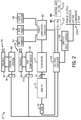
- FIG. 2 is a schematic diagram of an embodiment of a portable engine-driven generator system 70 employing an output power limiting device.
- the system 70 includes an engine 72 coupled to a generator 74 via a shaft 76.
- the engine 72 may be any suitable internal combustion engine (e.g., gasoline engine, diesel engine, etc.) for driving the generator 74.
- the engine 72 may be three-cylinder diesel engine, such as a 21.7 HP engine operating at an idle speed of approximately 1500 RPM and a welding speed of approximately 1850 RPM.
- Such an engine 72 may be manufactured by Caterpillar of Peoria, Illinois.
- the engine 72 may be a four-cylinder diesel engine, such as a 24.4 HP engine operating at an idle speed of approximately 1500 RPM and a welding speed of approximately 1850 RPM.
- a 24.4 HP engine operating at an idle speed of approximately 1500 RPM and a welding speed of approximately 1850 RPM.
- Such an engine 72 may be manufactured by Mitsubishi Engine North America, Inc. of Addison, Illinois. Although the engine 72 is depicted, certain embodiments may not include the engine 72.
- the system 70 may provide power appropriate for welding and/or plasma cutting operations.
- the engine 72 rotates the shaft 76 to drive the generator 74 which provides power output.
- the available output power from the generator 74 varies based on the generator 74 and engine 72 in the system 70.
- the generator 74 may have a rated peak power output of 12,000 watts and a rated continuous power output of 10,000 watts.
- a governor 78 is attached to the engine 72 to control the speed of the engine.
- the generator 74 provides power for welding and other powered equipment that may be coupled to the system 70.
- the generator 74 provides power to a power conversion circuitry 80 that may include circuit elements such as transformers, rectifiers, switches, and so forth. Such circuits are generally known in the art.
- the power conversion circuitry 80 may be configured to convert the generator 74 output power to a weld power 82, an auxiliary power 84, and power for a light system 86.
- the power conversion circuitry 80 may only be adapted to convert generator 74 output power to a weld power 82.
- the weld power 82 includes welding power that may be used for any type of welding operation (e.g., stick, MIG, TIG, etc.). As such, the weld power 82 may provide current output of approximately 20 to 410 amps and voltage output of approximately 14 to 40 VDC for welding.
- the auxiliary power 84 may be used to power electrical equipment separate from the system 70. Therefore, in certain embodiments the generator 74 may provide 120 VAC and/or 240 VAC at approximately 60 Hz.
- the light system power 86 may provide power to a lighting system used in conjunction with a welding operation.
- the system 70 may include a hydraulic system 88 and/or an air compressor 90.
- the hydraulic system 88 is coupled to valving 92 to enable hydraulic fluid to flow to and from other devices 94 to apply a usable force.
- the hydraulic system 88 may be used for a hydraulic lift, hydraulic actuator, hydraulic motor, etc.
- a clutch 96 is coupled to the hydraulic system 88 and may be engaged or disengaged to control the operation of the hydraulic system 88.
- the air compressor 90 is coupled to valving 98 to enable air to flow to and from devices 100 that use the compressed air.
- the air compressor 90 may be used for powering tools, providing compressed air to clean a surface, or to increase the air pressure in a device, such as a wheel.
- a clutch 102 is coupled to the air compressor 90 and may be engaged or disengaged to control the operation of the air compressor 90.
- Each clutch 96 and 102 may be any suitable clutch, such as a wrap spring clutch, belt clutch, or electric clutch.
- the clutches 96 and 102 may be coupled to the shaft 76, such as via a belt or chain, to drive the hydraulic system 88 and the air compressor 90 when the engine 72 rotates. As such, when clutch 96 is engaged, the engine 72 drives the hydraulic system 88 and when clutch 102 is engaged, the engine 72 drives the air compressor 90.
- the system 70 includes control circuitry 104 which may be configured to receive and process a plurality of inputs, such as limiting or lockout inputs 106.
- the control circuitry 104 may use the inputs 106 to determine instructions to send to the governor 78, power conversion circuitry 80, and clutches 96 and 102 to limit and/or inhibit the output or operation of such devices.
- the control circuitry 104 may include volatile or non-volatile memory, such as ROM, RAM, magnetic storage memory, optical storage memory, or a combination thereof.
- control parameters may be stored in the memory along with code configured to provide a specific output during operation (e.g., inhibit or limit use of weld power 82, inhibit or limit use of auxiliary power 84, inhibit use of hydraulic system 88, inhibit use of air compressor 90, etc.).
- the limiting or lockout input 106 receives instructions 108 which may limit or inhibit the use of any power output, process or processes, system, component, or other feature of the system 70.
- the limiting or lockout input 106 may be a keyhole, a connector, or a keypad as previously described in relation to FIG. 1 .
- the system 70 may include a transceiver 110 which may receive limiting instructions wirelessly from a controlling transceiver 112.
- the controlling transceiver 112 may be operated by a vendor to configure the system 70 for use by an operator renting the system 70.
- the operator renting the system 70 may desire and pay for limited functionality, therefore the vendor may limit the functionality of the system 70 to what the operator paid for.
- the transceiver 110 and the controlling transceiver 112 may be configured to communicate via a cellular or internet connection to enable the vendor to configure the system 70 remotely using the controlling transceiver 112.
- an operator may enter a store to rent the system 70.
- a store vendor may provide the operator with a total cost to rent the system 70.
- the operator may only desire some functionality of the system 70 for a reduced cost, therefore, the operator may be given a price list to use various functions or operating times of the system 70.
- the various functions provided to the operator may include: welding power for stick welding, welding power for MIG welding, welding power for TIG welding, welding current limited to 200 amps, welding current limited to 100 amps, auxiliary power, auxiliary power limited to 5000 watts, auxiliary power limited to 2500 watts, lighting system power, hydraulic system, and air compressor, for example.
- the various functions provided to the operator are not limited to the examples provided, but the examples merely represent possible configurations.
- an operator may be charged based on an operating time of various functions or of the complete system 70. Therefore, the system 70 may include limits on the amount of time various portions of the system 70 may be used. As such, a customer may purchase amounts of time they wish to use the system 70 or portions of the system 70. Like other purchases described, the system 70 may be programmed to be time limited using a wireless, wired, or other option.
- the operator may select specific options of the system 70 to be enabled. For example, the operator may select to only enable weld power 82 for stick welding and to enable the hydraulic system 88. After the operator makes a selection of their desired features, the operator pays for those features and the vendor configures the system 70 to enable the selected features using a vendor accessible input. For example, the vendor may send wireless signals using the controlling transceiver 112 with instructions to enable or inhibit system 70 features. In some embodiments, the vendor may insert a key into the limiting input 106 to select desired features. Likewise, a keypad or cable connection may be used to send instructions to the control circuitry 104. The control circuitry 104 receives the limiting, inhibiting, and/or enabling instructions and configures the system 70 using those instructions.
- control circuitry 104 may disable the hydraulic system 88 or the air compressor 90 by sending a control signal to either the clutch 96 or the clutch 102 that causes the clutch to remain disengaged.
- control circuitry 104 may disable or limit the weld power 82, the auxiliary power 84, or the light system 86 by sending a control signal to the power conversion circuitry 80 instructing the power conversion circuitry 80 to disable or limit the power.
- control circuitry 104 may send signals to the governor 78 to limit the engine speed 72. It should be noted that the limiting device or devices in the system 70 are not accessible to the operator (e.g., they are internal to the system 70 and/or protected by security codes, secure communication, or locks).
- FIG. 3 is a schematic diagram of another embodiment of a portable engine-driven generator system 120 employing an output power limiting device.
- switches 122, 124, 126, 128, and 130 may be used to inhibit use of portions of the system 120.
- the switches 122, 124, 126, 128, and 130 are controlled by the control circuitry 104.
- the switches 122, 124, 126, 128, and 130 may be relay, solid state, or another type of switch.
- the switches 122, 124, 126, 128, and 130 may be manual switches that may be actuated by a vendor. In such an embodiment, the switches may be within a locked compartment of the system 120, or the switches may be selected using one or more keys or other devices which an operator is inhibited from accessing.
- the vendor When a vendor inhibits an operator from using certain functionality of the system 120, the vendor sends instructions to the limiting or lockout input 106.
- the control circuitry 104 receives the instructions from the input 106 and limits or inhibits the functionality of the system 120 based on the limiting instructions. Furthermore, enabling instructions may be sent from the input 106 to the control circuitry 104.
- the control circuitry may cause any of the switches 122, 124, 126, 128, and 130 to be in an open or closed position in order to enable or disable portions of the system 120. More specifically, the control circuitry 104 may transition switch 122 to a closed position to enable weld power 82 to flow from the power conversion circuitry 80.
- control circuitry 104 may configure switches 124 and 126 to enable or disable use of auxiliary power 84 and the light system 86, respectively. Furthermore, the control circuitry 104 may transition switch 128 to a closed position to enable the clutch 96 to operate, therefore enabling use of the hydraulic system 88. Similarly, the control circuitry 104 may configure switch 130 to enable or disable use of the air compressor 90. Therefore, system 120 may enable or disable the use of its devices.
- FIG. 4 is a block diagram 140 of the control circuitry 104 of FIG. 2 employing an embodiment of an output power limiting device.
- Processing circuitry 142 of the control circuitry 104 may receive limiting instructions from the limiting or lockout input 106 and/or the transceiver 110.
- the processing circuitry 142 may use the instructions to limit the functionality of the engine-driven generator system 120.
- the processing circuitry 142 may include one or more microprocessors, such as one or more "general-purpose" microprocessors, one or more special-purpose microprocessors and/or ASICS, or some combination thereof.
- the processing circuitry 142 may include one or more reduced instruction set (RISC) processors.
- RISC reduced instruction set
- the control circuitry 104 also includes a memory device 144 and a storage device 146.
- the memory device 144 may include a volatile memory, such as random access memory (RAM), and/or a nonvolatile memory, such as read-only memory (ROM).
- RAM random access memory
- ROM read-only memory
- the memory device 144 may store a variety of information and may be used for various purposes.
- the memory device 144 may store processor-executable instructions (e.g., firmware or software) for the processing circuitry 142 to execute, such as instructions for limiting or inhibiting the functionality of the welding power, the auxiliary power, the lighting system power, the hydraulics system, the air compressor, etc.
- the storage device 146 may include ROM, flash memory, a hard drive, or any other suitable optical, magnetic, or solid-state storage medium, or a combination thereof.
- the storage device 146 may store data (e.g., security codes), instructions (e.g., software or firmware to limit functionality of the system 120), and any other suitable data.
- the processing circuitry 142 is configured to communicate with governor control circuitry 148 to control the operation of the governor 78. For example, the processing circuitry 142 may instruct the governor control circuitry 148 to adjust the limit of the engine 72 speed used by the governor 78. Furthermore, the processing circuitry 142 is configured to communicate with power control circuitry 150 to control the operation of the power conversion circuitry 80. For example, the processing circuitry 142 may instruct the power control circuitry 150 to inhibit the use of auxiliary power 84 produced by the power conversion circuitry 80.
- the processing circuitry 142 is configured to communicate with relay control circuitry 152 which controls the operation of relays 154. For example, the processing circuitry 142 may instruct the relay control circuitry 152 to control the relays 154 to open the switch providing auxiliary power 84.
- the processing circuitry 142 is configured to communicate with clutch control circuitry 156 which controls the operation of clutches 158. For example, the processing circuitry 142 may instruct the clutch control circuitry 156 to inhibit the use of the air compressor 90 by disengaging the clutch 102.
- the control circuitry 104 is configured to receive limiting inputs, process the inputs, and control power outputs based on the limiting inputs. Therefore, the control circuitry 104 functions as a output power limiting device within the engine-driven generator system 70.
- FIG. 5 is a flow chart of an embodiment of a business method 160 for renting out a portable engine-driven generator system.
- a vendor may receive a rental request from a customer for a portable engine-driven generator system.
- the vendor and customer determine which portions of the generator system to enable, limit, or inhibit.
- the vendor may enable or inhibit all portions of the generator system, or individual portions (e.g., weld power, auxiliary power, lighting system power, air compressor, and hydraulic system).
- the vendor configures the generator system with the enabling, limiting, or inhibiting instructions using an interface not accessible to the customer.
- the vendor may use secure wireless communications, a security key, a proprietary programming device or cable, a proprietary software, or other hardware or software to configure the generator system with limiting instructions.
- the generator system may include an internal log that contains a history of what devices and systems a customer has used. Such an internal log may be viewed by the vendor in cases where a vendor suspects a customer has tampered with the generator limiting devices. With such a system, as described, vendors may rent the generator system to customers at a variable cost based on the customer needs. As may be appreciated, fewer or more steps may be included in certain embodiments. In addition, other embodiments may perform the method 160 in a different order than described.
Landscapes
- Engineering & Computer Science (AREA)
- Physics & Mathematics (AREA)
- Plasma & Fusion (AREA)
- Mechanical Engineering (AREA)
- Theoretical Computer Science (AREA)
- Arc Welding Control (AREA)
Claims (15)
- Portables motorangetriebenes Generatorsystem, das Folgendes umfasst:eine Verbrennungskraftmaschine (72);einen Leistungsgenerator (74), der mit der Verbrennungskraftmaschine gekoppelt ist und dazu konfiguriert ist, durch die Verbrennungskraftmaschine angetrieben zu werden; undein durch einen ersten Bediener einstellbares Mittel zum Steuern einer Ausgangsleistung des Leistungsgenerators;dadurch gekennzeichnet, dass das System ferner Folgendes umfasst:ein nicht durch den ersten Bediener einstellbares Mittel (106) zum selektiven Begrenzen einer Ausgangsleistung von dem Leistungsgenerator zur Verwendung in dem Schweißbetrieb; undwobei das nicht durch den ersten Bediener einstellbare Mittel (106) durch einen zweiten Bediener einstellbar ist, um die Ausgangsleistung von dem Leistungsgenerator zu begrenzen.
- System nach Anspruch 1, das Folgendes umfasst:eine Leistungsumwandlungsschaltungsanordnung (80), die mit dem Leistungsgenerator (74) gekoppelt ist und dazu konfiguriert ist, eine Leistung von dem Leistungsgenerator (74) zu empfangen und die Ausgangsleistung bereitzustellen;wobei das durch einen ersten Bediener einstellbare Mittel wenigstens eine bedienerzugängliche Eingabe zum Empfangen eines Bedienereingabeparameters umfasst und wobei das nicht durch den ersten Bediener einstellbare Mittel (106) eine Ausgangsleistungsbegrenzungsvorrichtung umfasst, die dazu konfiguriert ist, eine Ausgangsleistung von der Leistungswandlungsschaltungsanordnung selektiv zu begrenzen.
- System nach Anspruch 2, wobei die Ausgangsleistungsbegrenzungsvorrichtung dazu konfiguriert ist, einen Leistungspegel und/oder einen Strompegel und/oder einen Spannungspegel der Ausgangsleistung zu begrenzen.
- System nach Anspruch 2, wobei die Ausgangsleistungsbegrenzungsvorrichtung dazu konfiguriert ist, eine Verwendung von wenigstens einem von mehreren Schweißprozessen zu begrenzen.
- System nach Anspruch 1, das ein Hydrauliksystem (88) umfasst, das mit der Verbrennungskraftmaschine (72) gekoppelt ist und dazu konfiguriert ist, durch die Verbrennungskraftmaschine (72) angetrieben zu werden, und wobei die Ausgangsleistungsbegrenzungsvorrichtung dazu konfiguriert ist, eine Verwendung des Hydrauliksystems (88) zu begrenzen.
- System nach Anspruch 1, das einen Luftkompressor (90) umfasst, der mit der Verbrennungskraftmaschine (72) gekoppelt ist und dazu konfiguriert ist, durch die Verbrennungskraftmaschine (72) angetrieben zu werden, und wobei die Ausgangsleistungsbegrenzungsvorrichtung dazu konfiguriert ist, eine Verwendung des Luftkompressors (90) zu verhindern.
- System nach Anspruch 2, das einen Lichtsystemausgang (86) umfasst, der mit der Leistungsumwandlungsschaltungsanordnung (80) gekoppelt ist und dazu konfiguriert ist, eine Leistung von der Leistungsumwandlungsschaltungsanordnung (80) zu empfangen, wobei die Ausgangsleistungsbegrenzungsvorrichtung dazu konfiguriert ist, eine Verwendung des Lichtsystemausgangs zu verhindern.
- System nach Anspruch 2, wobei die Ausgangsleistungsbegrenzungsvorrichtung einen physischen Schalter oder einen elektronischen Schalter umfasst.
- System nach Anspruch 2, wobei die Ausgangsleistungsbegrenzungsvorrichtung eine Steuerschaltungsanordnung (104) umfasst, die mit einem Drahtlosempfänger (110) gekoppelt ist, und wobei die Ausgangsleistungsbegrenzungsvorrichtung dazu konfiguriert ist, ein Drahtlossignal zum Steuern der Ausgangsleistungsbegrenzungsvorrichtung zu empfangen.
- System nach Anspruch 2, wobei die Ausgangsleistungsbegrenzungsvorrichtung dazu konfiguriert ist, zu verhindern, dass die Schweißleistung verwendet wird.
- System nach Anspruch 2, wobei die Leistungsumwandlungsschaltungsanordnung (80) dazu konfiguriert ist, eine Hilfsleistung (84) zum Versorgen einer elektrischen Vorrichtung mit Leistung bereitzustellen, und wobei die Ausgangsleistungsbegrenzungsvorrichtung dazu konfiguriert ist, zu verhindern, dass eine Hilfsleistung verwendet wird.
- System nach Anspruch 2, wobei die Ausgangsleistungsbegrenzungsvorrichtung dazu konfiguriert ist, eine Ausgangsleistung unter Verwendung einer vorbestimmten Verwendungszeit zu begrenzen.
- Schweißleistungsversorgungsbegrenzungsverfahren, das Folgendes umfasst:Empfangen einer Mietanfrage von einem Kunden für ein portables motorangetriebenes Generatorsystem;dadurch gekennzeichnet, dass das Verfahren ferner Folgendes umfasst:Bestimmen von zu begrenzenden Teilen des portablen motorangetriebenen Generatorsystems (70) unter Verwendung von Parameter von dem Kunden; undKonfigurieren des portablen motorangetriebenen Generatorsystems (70) dazu, die bestimmten Teile des portablen motorangetriebenen Generatorsystems (70) unter Verwendung einer Schnittstelle (106), die für den Kunden nicht zugänglich ist, zu begrenzen.
- Verfahren nach Anspruch 13, wobei die Teile des portablen motorangetriebenen Generatorsystems (70) eine Schweißleistung und/oder eine Hilfsleistung und/oder ein Lichtsystem und/oder ein Hydrauliksystem und/oder einen Luftkompressor beinhalten.
- Verfahren nach Anspruch 13, wobei die Schnittstelle (106) einen Schlüssel oder eine Drahtloskommunikation umfasst.
Applications Claiming Priority (3)
| Application Number | Priority Date | Filing Date | Title |
|---|---|---|---|
| US35598510P | 2010-06-17 | 2010-06-17 | |
| US13/105,580 US10773327B2 (en) | 2010-06-17 | 2011-05-11 | System and method for limiting welding output and ancillary features |
| PCT/US2011/040401 WO2011163018A1 (en) | 2010-06-17 | 2011-06-14 | Systems and method for limiting welding output and ancillary features |
Publications (2)
| Publication Number | Publication Date |
|---|---|
| EP2582482A1 EP2582482A1 (de) | 2013-04-24 |
| EP2582482B1 true EP2582482B1 (de) | 2017-08-30 |
Family
ID=45327739
Family Applications (1)
| Application Number | Title | Priority Date | Filing Date |
|---|---|---|---|
| EP11726637.9A Not-in-force EP2582482B1 (de) | 2010-06-17 | 2011-06-14 | Tragbares mit einem motor führendes system und verfahren zur begrenzung der schweissleistung |
Country Status (6)
| Country | Link |
|---|---|
| US (2) | US10773327B2 (de) |
| EP (1) | EP2582482B1 (de) |
| BR (1) | BR112012032190A2 (de) |
| CA (1) | CA2802864A1 (de) |
| MX (1) | MX2012014953A (de) |
| WO (1) | WO2011163018A1 (de) |
Families Citing this family (19)
| Publication number | Priority date | Publication date | Assignee | Title |
|---|---|---|---|---|
| CN103747912B (zh) * | 2011-05-26 | 2016-08-17 | 维克托设备公司 | 产生焊接的系统及利用基于计算的焊接输出功率的电压和送丝速度的修正控制焊机的方法 |
| CA2837384A1 (en) | 2011-05-26 | 2012-11-29 | Thermal Dynamics Corporation | Welding process with provision of a pulse period at the start |
| US10144083B2 (en) * | 2013-02-22 | 2018-12-04 | Illinois Tool Works Inc. | Multi-operator engine driven welder system |
| US9770776B2 (en) * | 2013-09-12 | 2017-09-26 | Lincoln Global, Inc. | Alternative power for engine driven welder |
| US10416701B2 (en) | 2015-09-03 | 2019-09-17 | Lincoln Global, Inc. | Systems and methods of controlling a maximum power output level of an engine-driven power source system |
| US10162375B2 (en) | 2015-09-03 | 2018-12-25 | Lincoln Global, Inc. | Power source system with remotely configurable power source |
| US10371039B2 (en) * | 2016-04-29 | 2019-08-06 | Illinois Tool Works Inc. | Power systems and enclosures having improved cooling air flow |
| US10651539B2 (en) * | 2016-05-04 | 2020-05-12 | Briggs & Stratton Corporation | Mounting arrangement for wireless communication board for a portable generator |
| US11149617B2 (en) * | 2016-08-19 | 2021-10-19 | Kohler Co. | System and method for low CO emission engine |
| US10751825B2 (en) * | 2016-10-28 | 2020-08-25 | Illinois Tool Works Inc. | Engine-driven welding-type power supplies with portable welding units |
| US10933484B2 (en) | 2017-08-31 | 2021-03-02 | Illinois Tool Works Inc. | Engine-driven welding-type power supplies configured to simultaneously use external and engine power |
| US11909161B2 (en) * | 2018-03-07 | 2024-02-20 | Relibond Aps | Power cable end treatment device |
| US11338382B2 (en) | 2018-04-04 | 2022-05-24 | Lincoln Global, Inc. | Welding equipment security |
| JP7055710B2 (ja) * | 2018-06-28 | 2022-04-18 | 株式会社やまびこ | エンジン駆動溶接機 |
| US12594618B2 (en) | 2019-09-09 | 2026-04-07 | Illinois Tool Works Inc. | Welding power supplies and user interfaces for welding power supplies |
| EP4008470A1 (de) * | 2020-12-01 | 2022-06-08 | Fronius International GmbH | Verfahren zur limitierung einer schweissleistung eines schweissgeräts |
| WO2023039637A1 (en) * | 2021-09-17 | 2023-03-23 | ASF Technologies (Australia) Pty Ltd | Remote control generator |
| CN115822789A (zh) * | 2021-09-17 | 2023-03-21 | 赛德动力科技(广东)有限公司 | 远程控制发电机 |
| US12018602B2 (en) * | 2022-06-30 | 2024-06-25 | Illinois Tool Works Inc. | Power systems with a rear surface exhaust |
Family Cites Families (63)
| Publication number | Priority date | Publication date | Assignee | Title |
|---|---|---|---|---|
| US4307690A (en) | 1980-06-05 | 1981-12-29 | Rockwell International Corporation | Electronic, variable speed engine governor |
| US4908746A (en) * | 1986-10-15 | 1990-03-13 | United States Data Corporation | Industrial control system |
| US4816647A (en) * | 1987-11-13 | 1989-03-28 | General Electric Company | Power control for appliance having a glass ceramic cooking surface |
| JP2570628B2 (ja) | 1994-09-21 | 1997-01-08 | 日本電気株式会社 | 半導体パッケージおよびその製造方法 |
| US5591362A (en) | 1995-02-03 | 1997-01-07 | The Miller Group, Ltd. | Idle solenoid for engine driven welder |
| US5805442A (en) * | 1996-05-30 | 1998-09-08 | Control Technology Corporation | Distributed interface architecture for programmable industrial control systems |
| US5925268A (en) * | 1996-06-06 | 1999-07-20 | Engauge Inc. | Laser welding apparatus employing a tilting mechanism and seam follower |
| US5808885A (en) * | 1996-12-20 | 1998-09-15 | Square D Company | Weld controller system for coupling to a common database system on a communication network |
| US5968385A (en) * | 1997-05-19 | 1999-10-19 | Illinois Tool Works Inc. | Engine driven inverter welding power supply |
| GB2325533B (en) * | 1997-05-22 | 2001-08-08 | Ceramaspeed Ltd | Method and apparatus for controlling an electric heater |
| US6107601A (en) * | 1997-10-01 | 2000-08-22 | Matsushita Electric Industrial Co., Ltd. | Apparatus and method for controlling an arc welding robot |
| US6040555A (en) * | 1998-02-20 | 2000-03-21 | Illinois Tool Works Inc. | Remote control for welders and method therefor |
| US6410066B1 (en) * | 1998-11-06 | 2002-06-25 | Fmc Technologies, Inc. | Controller and method for administering and providing on-line handling of deviations in a continuous oven cooking process |
| US6525301B1 (en) * | 1999-01-13 | 2003-02-25 | General Electric Company | Combination oven with manual entry of control algorithms |
| US6486453B1 (en) * | 1999-09-13 | 2002-11-26 | Maytag Corporation | Menu driven control system for a cooking appliance |
| US6396032B1 (en) * | 2000-02-29 | 2002-05-28 | Athena Controls, Inc. | Oven temperature control circuit |
| US6518995B1 (en) * | 2000-07-10 | 2003-02-11 | Jagannath Rao Ghole | System and process for remote, in situ metal work |
| US6624388B1 (en) * | 2001-01-25 | 2003-09-23 | The Lincoln Electric Company | System and method providing distributed welding architecture |
| US6486439B1 (en) * | 2001-01-25 | 2002-11-26 | Lincoln Global, Inc. | System and method providing automated welding information exchange and replacement part order generation |
| US7245875B2 (en) * | 2001-04-24 | 2007-07-17 | Lincoln Global, Inc. | System and method to facilitate wireless communication in a welding environment |
| US6636776B1 (en) * | 2001-07-09 | 2003-10-21 | Lincoln Global, Inc. | System and method for managing welding procedures and welding resources |
| US6660967B2 (en) * | 2001-08-28 | 2003-12-09 | Senco Products, Inc. | Power box |
| GB2380013A (en) * | 2001-09-21 | 2003-03-26 | Hewlett Packard Co | Automated Rental Procedure |
| US7574172B2 (en) * | 2001-09-25 | 2009-08-11 | Lincoln Global | System and method to facilitate wireless wide area communication in a welding environment |
| AU2003217663A1 (en) * | 2002-02-25 | 2003-09-09 | General Electric Company | Method and system for conditionally triggered system data capture |
| JP3861768B2 (ja) * | 2002-05-27 | 2006-12-20 | コベルコ建機株式会社 | 建設機械の盗難防止装置および建設機械の管理方法 |
| US7003695B2 (en) * | 2002-10-03 | 2006-02-21 | Seiko Epson Corporation | Undo/redo algorithm for a computer program |
| US6841760B2 (en) * | 2003-06-12 | 2005-01-11 | Maytag Corporation | Multiple current supply control system for a cooking appliance |
| US7205503B2 (en) * | 2003-07-24 | 2007-04-17 | Illinois Tool Works Inc. | Remotely controlled welding machine |
| US7745946B2 (en) * | 2004-01-10 | 2010-06-29 | Gary Carter, Sr. | Multifunction integrated portable power and utility apparatus |
| US7642487B2 (en) * | 2004-08-04 | 2010-01-05 | Lincoln Global, Inc. | Integrated engine welder and hydraulic pump |
| US7643890B1 (en) * | 2005-01-13 | 2010-01-05 | Lincoln Global, Inc. | Remote management of portable construction devices |
| DE102005004066A1 (de) * | 2005-01-20 | 2006-07-27 | E.G.O. Elektro-Gerätebau GmbH | Bedienverfahren für ein Elektrogerät und Bedieneinrichtung |
| US7687741B2 (en) * | 2005-02-03 | 2010-03-30 | Lincoln Global, Inc. | Triggering events in a welder with a real-time clock |
| US20070296223A1 (en) * | 2006-06-13 | 2007-12-27 | Saylor Industries, Inc. | Portable Combination Utility and Power Tool Unit |
| US20080078811A1 (en) * | 2006-09-15 | 2008-04-03 | The Lincoln Electric Company | Weld data acquisition |
| US7751926B2 (en) * | 2007-02-23 | 2010-07-06 | Illinois Tool Works, Inc. | Power source selector |
| US8653415B2 (en) * | 2007-04-30 | 2014-02-18 | Illinois Tool Works Inc. | Engine-driven air compressor/generator load priority control system and method |
| US20080281664A1 (en) * | 2007-05-07 | 2008-11-13 | David Matthew Campbell | System and method for managing use and availability of equipment |
| US8822884B2 (en) * | 2007-08-07 | 2014-09-02 | Lincoln Global, Inc. | Welding apparatus providing auxiliary power |
| US8248324B2 (en) | 2007-10-24 | 2012-08-21 | Lincoln Global, Inc. | Display with replica welding helmet viewer |
| US8261717B2 (en) * | 2008-02-04 | 2012-09-11 | Illinois Tool Works Inc. | Service pack power management |
| US8122486B2 (en) * | 2008-04-09 | 2012-02-21 | Embarq Holdings Company Llc | Method and system for secure management of co-located customer premises equipment |
| US8847115B2 (en) * | 2008-06-16 | 2014-09-30 | Illinois Tool Works Inc. | Configurable welding interface for automated welding applications |
| US20100012635A1 (en) * | 2008-07-15 | 2010-01-21 | Illinois Tools Works Inc. | Visually designated user interface for welder |
| US8106530B2 (en) * | 2008-08-28 | 2012-01-31 | Cisco Technology, Inc. | Network-centric scheduled power provisioning method |
| US9796037B2 (en) * | 2009-01-30 | 2017-10-24 | Illinois Tool Works Inc. | Integrated engine-driven generator control system |
| US8115328B2 (en) * | 2009-01-30 | 2012-02-14 | Illinois Tool Works Inc. | Weld setting based engine-driven generator control system and method |
| US8125094B2 (en) * | 2009-01-30 | 2012-02-28 | Illinois Tool Works Inc. | Engine-driven generator speed control system and method |
| US8274013B2 (en) * | 2009-03-09 | 2012-09-25 | Lincoln Global, Inc. | System for tracking and analyzing welding activity |
| US8436489B2 (en) * | 2009-06-29 | 2013-05-07 | Lightsail Energy, Inc. | Compressed air energy storage system utilizing two-phase flow to facilitate heat exchange |
| JP4806059B2 (ja) * | 2009-09-09 | 2011-11-02 | 株式会社東芝 | エネルギー管理システムおよびエネルギー管理方法 |
| US8185088B2 (en) | 2009-10-09 | 2012-05-22 | At&T Mobility Ii Llc | Mobile device leasing with customized operational features |
| US8569655B2 (en) * | 2009-10-13 | 2013-10-29 | Lincoln Global, Inc. | Welding helmet with integral user interface |
| US8569646B2 (en) * | 2009-11-13 | 2013-10-29 | Lincoln Global, Inc. | Systems, methods, and apparatuses for monitoring weld quality |
| US8445816B2 (en) | 2009-11-13 | 2013-05-21 | Lincoln Global, Inc. | Modular process list for welding power supply |
| US9421632B2 (en) * | 2009-12-29 | 2016-08-23 | Lincoln Global, Inc. | Multi-output engine welder supplying full electrical power capacity to a single welding output |
| WO2011091312A1 (en) * | 2010-01-22 | 2011-07-28 | Illinois Tool Works Inc. | Smart grid welding system |
| US8683980B2 (en) * | 2010-01-28 | 2014-04-01 | Cummins Power Generation, Inc. | Genset engine with an electronic fuel injection system integrating electrical sensing and crank position sensing |
| EP2360625A1 (de) * | 2010-02-15 | 2011-08-24 | Thomson Licensing | Rotationsaktivierte elektronische Komponente mit zeitbegrenzter Verwendung |
| US20120022882A1 (en) * | 2010-07-20 | 2012-01-26 | Lincoln Global, Inc. | Licensing features in welding equipment |
| US10820750B2 (en) * | 2014-08-05 | 2020-11-03 | Lynx Grills, Inc. | Computer-controlled grills |
| JP6765849B2 (ja) | 2016-04-28 | 2020-10-07 | キヤノン株式会社 | 振動型アクチュエータ及び電子機器 |
-
2011
- 2011-05-11 US US13/105,580 patent/US10773327B2/en active Active
- 2011-06-14 BR BR112012032190A patent/BR112012032190A2/pt not_active IP Right Cessation
- 2011-06-14 EP EP11726637.9A patent/EP2582482B1/de not_active Not-in-force
- 2011-06-14 WO PCT/US2011/040401 patent/WO2011163018A1/en not_active Ceased
- 2011-06-14 MX MX2012014953A patent/MX2012014953A/es active IP Right Grant
- 2011-06-14 CA CA2802864A patent/CA2802864A1/en not_active Abandoned
-
2017
- 2017-08-09 US US15/673,245 patent/US20170334012A1/en not_active Abandoned
Non-Patent Citations (1)
| Title |
|---|
| None * |
Also Published As
| Publication number | Publication date |
|---|---|
| CA2802864A1 (en) | 2011-12-29 |
| EP2582482A1 (de) | 2013-04-24 |
| US10773327B2 (en) | 2020-09-15 |
| BR112012032190A2 (pt) | 2016-11-22 |
| US20170334012A1 (en) | 2017-11-23 |
| US20110309053A1 (en) | 2011-12-22 |
| MX2012014953A (es) | 2013-06-07 |
| WO2011163018A1 (en) | 2011-12-29 |
Similar Documents
| Publication | Publication Date | Title |
|---|---|---|
| US10773327B2 (en) | System and method for limiting welding output and ancillary features | |
| US9676050B2 (en) | Welding system with lockout mechanism | |
| US9975522B2 (en) | Construction machine | |
| US10465719B2 (en) | Construction machine | |
| US20170058489A1 (en) | Construction Machine | |
| US20090193800A1 (en) | Service pack tandem pump | |
| EP3225345A1 (de) | System und verfahren für ferngesteuerte motorangetriebene schweissstromversorgung | |
| KR102301475B1 (ko) | 건설 기계 | |
| CN106059346A (zh) | 混合焊接电源 | |
| US20190041888A1 (en) | Power source system | |
| EP3421166A1 (de) | Stromquelle | |
| JP6869818B2 (ja) | 作業機 | |
| US5977730A (en) | Method and apparatus for controlling the flow of hydraulic fluid | |
| US10001148B2 (en) | Systems and methods for detecting a type of hydraulic device | |
| JP4722466B2 (ja) | 車両搭載型ハイブリッドクレーン | |
| US10766090B2 (en) | Control panels for power systems | |
| US10416701B2 (en) | Systems and methods of controlling a maximum power output level of an engine-driven power source system | |
| US11075581B2 (en) | Methods and apparatus to use a switched-mode power supply as a source of power in a service pack | |
| WO1998039840A1 (en) | Method and apparatus for controlling a lifting magnet of a materials handling machine | |
| JP5833304B2 (ja) | 車両運搬車 |
Legal Events
| Date | Code | Title | Description |
|---|---|---|---|
| PUAI | Public reference made under article 153(3) epc to a published international application that has entered the european phase |
Free format text: ORIGINAL CODE: 0009012 |
|
| 17P | Request for examination filed |
Effective date: 20130107 |
|
| AK | Designated contracting states |
Kind code of ref document: A1 Designated state(s): AL AT BE BG CH CY CZ DE DK EE ES FI FR GB GR HR HU IE IS IT LI LT LU LV MC MK MT NL NO PL PT RO RS SE SI SK SM TR |
|
| DAX | Request for extension of the european patent (deleted) | ||
| RAP1 | Party data changed (applicant data changed or rights of an application transferred) |
Owner name: ILLINOIS TOOL WORKS INC. |
|
| 17Q | First examination report despatched |
Effective date: 20140407 |
|
| GRAP | Despatch of communication of intention to grant a patent |
Free format text: ORIGINAL CODE: EPIDOSNIGR1 |
|
| INTG | Intention to grant announced |
Effective date: 20161004 |
|
| GRAJ | Information related to disapproval of communication of intention to grant by the applicant or resumption of examination proceedings by the epo deleted |
Free format text: ORIGINAL CODE: EPIDOSDIGR1 |
|
| INTC | Intention to grant announced (deleted) | ||
| GRAP | Despatch of communication of intention to grant a patent |
Free format text: ORIGINAL CODE: EPIDOSNIGR1 |
|
| INTG | Intention to grant announced |
Effective date: 20170320 |
|
| GRAS | Grant fee paid |
Free format text: ORIGINAL CODE: EPIDOSNIGR3 |
|
| GRAA | (expected) grant |
Free format text: ORIGINAL CODE: 0009210 |
|
| AK | Designated contracting states |
Kind code of ref document: B1 Designated state(s): AL AT BE BG CH CY CZ DE DK EE ES FI FR GB GR HR HU IE IS IT LI LT LU LV MC MK MT NL NO PL PT RO RS SE SI SK SM TR |
|
| REG | Reference to a national code |
Ref country code: GB Ref legal event code: FG4D |
|
| REG | Reference to a national code |
Ref country code: CH Ref legal event code: EP |
|
| REG | Reference to a national code |
Ref country code: AT Ref legal event code: REF Ref document number: 923054 Country of ref document: AT Kind code of ref document: T Effective date: 20170915 |
|
| REG | Reference to a national code |
Ref country code: IE Ref legal event code: FG4D |
|
| REG | Reference to a national code |
Ref country code: DE Ref legal event code: R096 Ref document number: 602011041064 Country of ref document: DE |
|
| REG | Reference to a national code |
Ref country code: NL Ref legal event code: MP Effective date: 20170830 |
|
| REG | Reference to a national code |
Ref country code: LT Ref legal event code: MG4D |
|
| REG | Reference to a national code |
Ref country code: AT Ref legal event code: MK05 Ref document number: 923054 Country of ref document: AT Kind code of ref document: T Effective date: 20170830 |
|
| PG25 | Lapsed in a contracting state [announced via postgrant information from national office to epo] |
Ref country code: HR Free format text: LAPSE BECAUSE OF FAILURE TO SUBMIT A TRANSLATION OF THE DESCRIPTION OR TO PAY THE FEE WITHIN THE PRESCRIBED TIME-LIMIT Effective date: 20170830 Ref country code: FI Free format text: LAPSE BECAUSE OF FAILURE TO SUBMIT A TRANSLATION OF THE DESCRIPTION OR TO PAY THE FEE WITHIN THE PRESCRIBED TIME-LIMIT Effective date: 20170830 Ref country code: AT Free format text: LAPSE BECAUSE OF FAILURE TO SUBMIT A TRANSLATION OF THE DESCRIPTION OR TO PAY THE FEE WITHIN THE PRESCRIBED TIME-LIMIT Effective date: 20170830 Ref country code: NO Free format text: LAPSE BECAUSE OF FAILURE TO SUBMIT A TRANSLATION OF THE DESCRIPTION OR TO PAY THE FEE WITHIN THE PRESCRIBED TIME-LIMIT Effective date: 20171130 Ref country code: LT Free format text: LAPSE BECAUSE OF FAILURE TO SUBMIT A TRANSLATION OF THE DESCRIPTION OR TO PAY THE FEE WITHIN THE PRESCRIBED TIME-LIMIT Effective date: 20170830 Ref country code: SE Free format text: LAPSE BECAUSE OF FAILURE TO SUBMIT A TRANSLATION OF THE DESCRIPTION OR TO PAY THE FEE WITHIN THE PRESCRIBED TIME-LIMIT Effective date: 20170830 |
|
| PG25 | Lapsed in a contracting state [announced via postgrant information from national office to epo] |
Ref country code: ES Free format text: LAPSE BECAUSE OF FAILURE TO SUBMIT A TRANSLATION OF THE DESCRIPTION OR TO PAY THE FEE WITHIN THE PRESCRIBED TIME-LIMIT Effective date: 20170830 Ref country code: IS Free format text: LAPSE BECAUSE OF FAILURE TO SUBMIT A TRANSLATION OF THE DESCRIPTION OR TO PAY THE FEE WITHIN THE PRESCRIBED TIME-LIMIT Effective date: 20171230 Ref country code: GR Free format text: LAPSE BECAUSE OF FAILURE TO SUBMIT A TRANSLATION OF THE DESCRIPTION OR TO PAY THE FEE WITHIN THE PRESCRIBED TIME-LIMIT Effective date: 20171201 Ref country code: BG Free format text: LAPSE BECAUSE OF FAILURE TO SUBMIT A TRANSLATION OF THE DESCRIPTION OR TO PAY THE FEE WITHIN THE PRESCRIBED TIME-LIMIT Effective date: 20171130 Ref country code: LV Free format text: LAPSE BECAUSE OF FAILURE TO SUBMIT A TRANSLATION OF THE DESCRIPTION OR TO PAY THE FEE WITHIN THE PRESCRIBED TIME-LIMIT Effective date: 20170830 Ref country code: RS Free format text: LAPSE BECAUSE OF FAILURE TO SUBMIT A TRANSLATION OF THE DESCRIPTION OR TO PAY THE FEE WITHIN THE PRESCRIBED TIME-LIMIT Effective date: 20170830 |
|
| PG25 | Lapsed in a contracting state [announced via postgrant information from national office to epo] |
Ref country code: NL Free format text: LAPSE BECAUSE OF FAILURE TO SUBMIT A TRANSLATION OF THE DESCRIPTION OR TO PAY THE FEE WITHIN THE PRESCRIBED TIME-LIMIT Effective date: 20170830 |
|
| PG25 | Lapsed in a contracting state [announced via postgrant information from national office to epo] |
Ref country code: DK Free format text: LAPSE BECAUSE OF FAILURE TO SUBMIT A TRANSLATION OF THE DESCRIPTION OR TO PAY THE FEE WITHIN THE PRESCRIBED TIME-LIMIT Effective date: 20170830 Ref country code: CZ Free format text: LAPSE BECAUSE OF FAILURE TO SUBMIT A TRANSLATION OF THE DESCRIPTION OR TO PAY THE FEE WITHIN THE PRESCRIBED TIME-LIMIT Effective date: 20170830 Ref country code: RO Free format text: LAPSE BECAUSE OF FAILURE TO SUBMIT A TRANSLATION OF THE DESCRIPTION OR TO PAY THE FEE WITHIN THE PRESCRIBED TIME-LIMIT Effective date: 20170830 Ref country code: PL Free format text: LAPSE BECAUSE OF FAILURE TO SUBMIT A TRANSLATION OF THE DESCRIPTION OR TO PAY THE FEE WITHIN THE PRESCRIBED TIME-LIMIT Effective date: 20170830 |
|
| PG25 | Lapsed in a contracting state [announced via postgrant information from national office to epo] |
Ref country code: SM Free format text: LAPSE BECAUSE OF FAILURE TO SUBMIT A TRANSLATION OF THE DESCRIPTION OR TO PAY THE FEE WITHIN THE PRESCRIBED TIME-LIMIT Effective date: 20170830 Ref country code: EE Free format text: LAPSE BECAUSE OF FAILURE TO SUBMIT A TRANSLATION OF THE DESCRIPTION OR TO PAY THE FEE WITHIN THE PRESCRIBED TIME-LIMIT Effective date: 20170830 Ref country code: IT Free format text: LAPSE BECAUSE OF FAILURE TO SUBMIT A TRANSLATION OF THE DESCRIPTION OR TO PAY THE FEE WITHIN THE PRESCRIBED TIME-LIMIT Effective date: 20170830 Ref country code: SK Free format text: LAPSE BECAUSE OF FAILURE TO SUBMIT A TRANSLATION OF THE DESCRIPTION OR TO PAY THE FEE WITHIN THE PRESCRIBED TIME-LIMIT Effective date: 20170830 |
|
| REG | Reference to a national code |
Ref country code: DE Ref legal event code: R097 Ref document number: 602011041064 Country of ref document: DE |
|
| REG | Reference to a national code |
Ref country code: FR Ref legal event code: PLFP Year of fee payment: 8 |
|
| PLBE | No opposition filed within time limit |
Free format text: ORIGINAL CODE: 0009261 |
|
| STAA | Information on the status of an ep patent application or granted ep patent |
Free format text: STATUS: NO OPPOSITION FILED WITHIN TIME LIMIT |
|
| 26N | No opposition filed |
Effective date: 20180531 |
|
| PG25 | Lapsed in a contracting state [announced via postgrant information from national office to epo] |
Ref country code: SI Free format text: LAPSE BECAUSE OF FAILURE TO SUBMIT A TRANSLATION OF THE DESCRIPTION OR TO PAY THE FEE WITHIN THE PRESCRIBED TIME-LIMIT Effective date: 20170830 |
|
| PGFP | Annual fee paid to national office [announced via postgrant information from national office to epo] |
Ref country code: GB Payment date: 20180627 Year of fee payment: 8 Ref country code: DE Payment date: 20180627 Year of fee payment: 8 |
|
| REG | Reference to a national code |
Ref country code: CH Ref legal event code: PL |
|
| REG | Reference to a national code |
Ref country code: BE Ref legal event code: MM Effective date: 20180630 |
|
| REG | Reference to a national code |
Ref country code: IE Ref legal event code: MM4A |
|
| PG25 | Lapsed in a contracting state [announced via postgrant information from national office to epo] |
Ref country code: MC Free format text: LAPSE BECAUSE OF FAILURE TO SUBMIT A TRANSLATION OF THE DESCRIPTION OR TO PAY THE FEE WITHIN THE PRESCRIBED TIME-LIMIT Effective date: 20170830 Ref country code: LU Free format text: LAPSE BECAUSE OF NON-PAYMENT OF DUE FEES Effective date: 20180614 |
|
| PG25 | Lapsed in a contracting state [announced via postgrant information from national office to epo] |
Ref country code: LI Free format text: LAPSE BECAUSE OF NON-PAYMENT OF DUE FEES Effective date: 20180630 Ref country code: CH Free format text: LAPSE BECAUSE OF NON-PAYMENT OF DUE FEES Effective date: 20180630 Ref country code: IE Free format text: LAPSE BECAUSE OF NON-PAYMENT OF DUE FEES Effective date: 20180614 |
|
| PG25 | Lapsed in a contracting state [announced via postgrant information from national office to epo] |
Ref country code: BE Free format text: LAPSE BECAUSE OF NON-PAYMENT OF DUE FEES Effective date: 20180630 |
|
| REG | Reference to a national code |
Ref country code: DE Ref legal event code: R119 Ref document number: 602011041064 Country of ref document: DE |
|
| PG25 | Lapsed in a contracting state [announced via postgrant information from national office to epo] |
Ref country code: MT Free format text: LAPSE BECAUSE OF NON-PAYMENT OF DUE FEES Effective date: 20180614 |
|
| GBPC | Gb: european patent ceased through non-payment of renewal fee |
Effective date: 20190614 |
|
| PG25 | Lapsed in a contracting state [announced via postgrant information from national office to epo] |
Ref country code: TR Free format text: LAPSE BECAUSE OF FAILURE TO SUBMIT A TRANSLATION OF THE DESCRIPTION OR TO PAY THE FEE WITHIN THE PRESCRIBED TIME-LIMIT Effective date: 20170830 |
|
| PG25 | Lapsed in a contracting state [announced via postgrant information from national office to epo] |
Ref country code: DE Free format text: LAPSE BECAUSE OF NON-PAYMENT OF DUE FEES Effective date: 20200101 Ref country code: GB Free format text: LAPSE BECAUSE OF NON-PAYMENT OF DUE FEES Effective date: 20190614 |
|
| PG25 | Lapsed in a contracting state [announced via postgrant information from national office to epo] |
Ref country code: HU Free format text: LAPSE BECAUSE OF FAILURE TO SUBMIT A TRANSLATION OF THE DESCRIPTION OR TO PAY THE FEE WITHIN THE PRESCRIBED TIME-LIMIT; INVALID AB INITIO Effective date: 20110614 Ref country code: PT Free format text: LAPSE BECAUSE OF FAILURE TO SUBMIT A TRANSLATION OF THE DESCRIPTION OR TO PAY THE FEE WITHIN THE PRESCRIBED TIME-LIMIT Effective date: 20170830 |
|
| PG25 | Lapsed in a contracting state [announced via postgrant information from national office to epo] |
Ref country code: CY Free format text: LAPSE BECAUSE OF FAILURE TO SUBMIT A TRANSLATION OF THE DESCRIPTION OR TO PAY THE FEE WITHIN THE PRESCRIBED TIME-LIMIT Effective date: 20170830 Ref country code: MK Free format text: LAPSE BECAUSE OF NON-PAYMENT OF DUE FEES Effective date: 20170830 |
|
| PG25 | Lapsed in a contracting state [announced via postgrant information from national office to epo] |
Ref country code: AL Free format text: LAPSE BECAUSE OF FAILURE TO SUBMIT A TRANSLATION OF THE DESCRIPTION OR TO PAY THE FEE WITHIN THE PRESCRIBED TIME-LIMIT Effective date: 20170830 |
|
| PGFP | Annual fee paid to national office [announced via postgrant information from national office to epo] |
Ref country code: FR Payment date: 20200625 Year of fee payment: 10 |
|
| PG25 | Lapsed in a contracting state [announced via postgrant information from national office to epo] |
Ref country code: FR Free format text: LAPSE BECAUSE OF NON-PAYMENT OF DUE FEES Effective date: 20210630 |