EP2581698A2 - Spürvorrichtung für Bodenspürungen aus dem Inneren eines Fahrzeugs und Verfahren zum Bodenspüren - Google Patents
Spürvorrichtung für Bodenspürungen aus dem Inneren eines Fahrzeugs und Verfahren zum Bodenspüren Download PDFInfo
- Publication number
- EP2581698A2 EP2581698A2 EP12183350.3A EP12183350A EP2581698A2 EP 2581698 A2 EP2581698 A2 EP 2581698A2 EP 12183350 A EP12183350 A EP 12183350A EP 2581698 A2 EP2581698 A2 EP 2581698A2
- Authority
- EP
- European Patent Office
- Prior art keywords
- sensing head
- height adjustment
- sensing
- vehicle
- alignment
- Prior art date
- Legal status (The legal status is an assumption and is not a legal conclusion. Google has not performed a legal analysis and makes no representation as to the accuracy of the status listed.)
- Granted
Links
Images


Classifications
-
- F—MECHANICAL ENGINEERING; LIGHTING; HEATING; WEAPONS; BLASTING
- F41—WEAPONS
- F41H—ARMOUR; ARMOURED TURRETS; ARMOURED OR ARMED VEHICLES; MEANS OF ATTACK OR DEFENCE, e.g. CAMOUFLAGE, IN GENERAL
- F41H7/00—Armoured or armed vehicles
- F41H7/02—Land vehicles with enclosing armour, e.g. tanks
- F41H7/03—Air-pressurised compartments for crew; Means for preventing admission of noxious substances, e.g. combustion gas from gun barrels, in crew compartments; Sealing arrangements
-
- F—MECHANICAL ENGINEERING; LIGHTING; HEATING; WEAPONS; BLASTING
- F41—WEAPONS
- F41H—ARMOUR; ARMOURED TURRETS; ARMOURED OR ARMED VEHICLES; MEANS OF ATTACK OR DEFENCE, e.g. CAMOUFLAGE, IN GENERAL
- F41H7/00—Armoured or armed vehicles
- F41H7/02—Land vehicles with enclosing armour, e.g. tanks
Definitions
- the invention relates to a tracing device for floor tracing from the interior of a vehicle having a sensing head which can be brought into contact with the ground, which can be aligned by actuating an alignment device in a tracing area above the ground.
- Another object of the invention is a vehicle. Also described is a method of sensing ground from within a vehicle having a sensing device that includes a ground engaging feeler head that is aligned by operating an alignment device in a sensing area above the ground.
- Tracing devices for ground detections are used in particular military vehicles, for example, to detect harmful substances and warfare agents in the ground and thus in the environment of the vehicle can.
- Such vehicles are often designed as detection vehicles or detection armor.
- a well-known tracking vehicle with a tracing device describes the DE 10 2009 015 828 A1 ,
- the sensing device has a sensing head, which is arranged at the free end of a guided through the vehicle floor, pivotable tube. About the sensing head harmful and warfare agents can be evaporated from the ground and / or the ambient air and passed to an analysis device inside the vehicle.
- an alignment device is provided in the manner of a linkage with a handle. The tracker operating the detection device can align the detection head by actuating the handle in a detection area above the ground. Furthermore, by means of the alignment device, the tracker can lower the sensing head under leverage into a sensing position in which the sensing head is in contact with the ground, and then apply a contact pressure to the sensing head in the sensing position.
- the maximum stroke of the sensing head is limited by the alignment device.
- the sensing head can thus be raised from the ground detection position only in a small height above the ground in the rest position.
- the ground clearance of the vehicle may be limited by the sensing device.
- the invention has as its object to enable an improved ground clearance of the vehicle.
- the object is achieved by a arranged between the alignment and the sensing head height adjustment device for adjusting the height of the sensing head above the ground.
- the height adjustment device may be disposed between the alignment device and the sensing head such that it is connected to the alignment device and to the sensing head. By the height adjustment device, an additional stroke of the sensing head can be made possible. Thus, the ground clearance can be increased by the height adjustment.
- the height adjustment device can be used to raise the sensing head from the detection position to the rest position.
- the height adjustment device can be actuated independently of the alignment device.
- the sensing head can be aligned via the alignment device.
- the lowering and / or raising of the probe can be done via the height adjustment device, wherein the alignment can be in any position.
- the height of the sensing head can be adjusted separately by the height adjustment.
- the height adjustment device is manually operable, so that the lowering of the sensing head can be done via the movements of the sensing device serving tracker.
- the sensing device may include an actuating mechanism for actuating the height adjustment device, which is operable by the tracker.
- the height adjustment device can be actuated by a motor.
- a motorized operation of the height adjustment device has the advantage that the force required by the tracker when lowering and / or pressing the sensing head is reduced.
- a linear drive is preferably provided, so that the sensing head is translationally movable.
- the linear drive can be electromechanical, hydraulic or pneumatic.
- the height adjustment device can be operated via a crank. Via a crank, a torque for lowering and / or for pressing the sensing head can be provided.
- the height adjustment device has a threaded spindle.
- a rotational movement such as a crank or a drive, are converted into a translational movement of the sensing head.
- the height adjustment device in particular the threaded spindle, formed lockable.
- a lockable height adjustment device can the sensing head are set at a predetermined height above the ground in an air sensing position in which pollutants and warfare agents can be taken from the air.
- the height adjustment device has a self-locking threaded spindle. By a self-locking threaded spindle, the locking of the sensing head can be made possible without additional locking devices.
- the sensing head in particular by the alignment, about a hinge point is pivotally, wherein the hinge point is lowered by the height adjustment device.
- the pivot point can be lowered in the direction of the vehicle floor. Since the maximum possible pivoting angle of the sensing head increases with the lowering of the pivot point in the direction of the opening in the vehicle floor, when the pivot point is lowered, a larger detection area can be scanned with the sensing head.
- the hinge point is preferably designed as a ball joint, so that the sensing head is pivotable by the alignment device on a spherical surface about the hinge point. With appropriate alignment by the alignment and lowering by the height adjustment device of the sensing head can thus be aligned in a substantially elliptical detection area on the floor below the vehicle.
- the height adjustment device is rigidly connected to the alignment device.
- the height adjustment device can be moved to align the sensing head with the alignment device.
- the height adjustment device is pivotally coupled to the alignment device.
- the alignment device has an adjustment device for adapting the alignment device to the size of the tracker.
- the adaptation device can be adjustable in such a way that detectors of different body size and / or arm length can operate the alignment device.
- the alignment device may include a handle for aligning the sensing head.
- the handle can be rotatably supported by a rotary bearing about an axis of rotation.
- an angular position of the handle on the adjustment device can be adjustable.
- angular positions of 0 °, 20 ° and 40 ° are adjustable.
- the angle which the sections include may be arbitrary.
- Another object of the invention is a vehicle, in particular a tracking vehicle.
- the object is achieved in that a sensing device described above is provided.
- the sensing head By arranged between the alignment and the sensing head height adjustment device, an additional stroke of the sensing head can be made possible.
- the sensing head can be lowered and raised regardless of the respective ground clearance of the vehicle by the height adjustment device.
- the ground clearance of the vehicle can be increased by the height adjustment.
- the detection head can first be aligned with the alignment device above the floor and then lowered by means of the height adjustment device in the direction of the floor.
- an additional stroke of the sensing head can be made possible by the arranged between the alignment and the sensing head height adjustment device and the ground clearance of the vehicle can be improved overall.
- a contact pressure for pressing the sensing head is exerted on the ground by the height adjustment device.
- the sensing head can be brought into contact with the ground via the height adjustment device and then pressed against the ground via the height adjustment device in such a way that the contact pressure required for receiving soil samples is set.
- FIG. 1 and Fig. 2 show a military vehicle 1, which is designed as a tracking vehicle.
- a seat 3 is provided, from which a person referred to below as a tracker 2 can operate a tracing device 9 of the vehicle 1.
- the representation in Fig. 2 shows the interior 7 of the vehicle 1 in a plan view.
- the sensing device 9 is arranged next to the seat 3, as it is known from parking brakes in passenger vehicles.
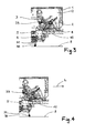
- the detection device 9 has an alignment device 10, which is arranged in the interior 7 of the vehicle and via which a sensing head 30 of the detection device 9 can be aligned above the ground, cf. Fig. 3 and FIG. 4 , Again FIG. 3 and FIG. 4 can also be seen, the sensing head 30 at the lower end of a tube 31 is arranged, which is guided through a shaft 5 in the vehicle floor panel 4.
- the sensing head 30 has an evaporator through which air or soil samples are transferred to a vaporous state.
- the evaporator is designed in the manner of a heating element.
- the tube 31 serves to guide through the sensing head 30 vaporized air and / or soil samples in the interior of the vehicle 1 and supply an analysis device, not shown.
- a tube 31 surrounding the bellows 32 is provided.
- the shaft 5 is sealed for the passage of the tube 31 through the vehicle floor 4 so flexible that alignment and lowering movements of the tube 31 and the sensing head 30 are possible .
- a ball bearing may be provided in the vehicle floor 4 or in the shaft 5.
- a height adjustment device 20 is provided on the sensing device 9, which is arranged between the alignment device 10 and the sensing head 30.
- the stroke of the sensing head 30 can be increased.
- the sensing head 30 can be lowered by the height adjustment device 10 from the rest position to the detection position and raised by the detection position in the rest position. It is therefore not necessary to effect the lowering of the sensing head 30 by the alignment device 10.
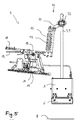
- the Fig. 5 shows the sensing device 9 in a rest position in which the sensing head 30 is located in a protected from environmental influences position within the shaft 5.
- the flaps 6, which close the shaft 5 downwards, closed in the rest position In order to protect the sensing head 30 while driving with the vehicle 1 from undesired contact with protruding from the ground 8 objects, the flaps 6, which close the shaft 5 downwards, closed in the rest position.
- an alignment device 10 is provided on the sensing device 9, which is operable via a handle 11.
- the handle 11 is formed in the manner of a substantially elongated rocker, which can be pivoted about a pivot bearing 13 in a substantially horizontal direction.
- the handle 11 is pivotable together with the pivot bearing 13 via a second pivot bearing 14 in a substantially horizontal plane.
- the axes of rotation of the pivot bearings 13 and 14 are oriented perpendicular to each other.
- the alignment device 10 has a linear guide 15, via which the handle 11 and the pivot bearings 13 and 14 can be moved in the direction of a vehicle longitudinal axis L.
- the height adjustment device 20 the height H of the sensing head 30 is arbitrary, so that any height H between the rest position and a Ground detection position in which the sensing head 30 is in contact with the bottom 8, can be adjusted.
- the height adjustment device 20 is rigidly connected to the alignment device 10 and coupled via a designed as a ball joint 33 pivot point with the tube 31. Due to the connection of the height adjustment device 20 between the alignment device 10 and the tube 31, movements of the alignment device 10 can be transmitted to the tube 31. While the height H of the sensing head is adjusted via the height adjustment device 20, the alignment of the sensing head 30 by the alignment device 10 can thus take place. If the alignment device 10, for example, as in the Fig. 3 shown displaced along the linear guide 15 in the direction of the front end of the vehicle interior 7, the sensing head 30 is aligned in the sensing area above the bottom 8 in an opposite direction. Moves the tracker 2, the alignment device 10 in the direction of its trunk, so alignment of the sensing head 30 in the direction of the front in the direction of travel of the detection area, see. Fig. 4 ,
- a camera not shown in the figures may be arranged, by means of which the alignment, the lowering and the actual sensing via a monitor, also not shown in the interior 7 of the vehicle 1 is observable.
- the height adjustment device 20 a threaded spindle 21, on which a spindle nut 26 is received.
- a bellows 22 is provided, which surrounds the threaded spindle 21, see.
- the spindle nut 26 is connected via a formed in the manner of a link arm 24 with the ball joint 33.
- a linear guide 23 is provided for guiding the connecting member 24 in the direction of the threaded spindle 21, which is aligned parallel to the threaded spindle 21.
- the connecting member 24 has a guide element 27, which is guided on the linear guide 23.
- the connecting member 24 is pivotally connected to the tube 31 via the ball joint 33.
- the position of the spindle nut 26 on the threaded spindle 21 can be easily changed by hand and thus the height H of the sensing head 30 can be adjusted.
- the threaded spindle 21 is self-locking, so that the spindle nut 26 can be stopped in any position on the threaded spindle 21 without changing your position by itself. Due to the self-locking threaded spindle 21, the sensing head 30 can be locked in an air sensing position at any height H above the ground 8.
- a drive for actuating the threaded spindle 21 may be provided on the height adjustment device 20, so that there is a linear drive in the manner of a spindle drive.
- other linear actuators for. B. a hydraulic cylinder, a pneumatic cylinder or an electromechanical linear actuator for adjusting the height H to be arranged on the height adjustment device 20.
- the alignment device in the pivot bearings 13 and 14 and in the linear guide 15 each have a brake which can be actuated via a brake lever 12.
- the brake lever 12 hingedly connected to the handle 11 and biased by a spring 16 against the handle 11.
- the handle 11 also has a handle shell 17, in which the hand of the spur 2 can be received during actuation of the handle 11.
- the angular position of the handle 11 is adjustable.
- the handle 11 has a portion 11.1, which is connected via a hinge 18 pivotally connected to a second portion 11.2.
- By semicircular openings arranged in the overlapping areas of the sections 11.1 and 11.2 more screws 19 for locking the angular position of the sections 11.1 and 11.2 are guided to each other.
- Fig. 7 are three different angular positions of the section 11.1 relative to the section 11.2 adjustable.
- the section 11.1 can be pivoted relative to the section 11.2 by 0 °, 20 ° and 40 °.
- the adjustment of the two sections 11.1 and 11.2 could be designed such that an arbitrary pivot angle is adjustable.
- the sensing device 9 described above may be used in the method for detecting ground from the interior 7 of a vehicle 1. According to the methods, the sensing head 30 of the sensing device 9 is lowered by the height adjustment device 20 in the direction of the bottom 8 and aligned by the alignment device 10 in the detection area. The alignment and lowering can be done manually by the tracker 2.
- an optionally required contact pressure on the sensing head 30 can be exerted via the height adjustment device 20 by the crank 25 being rotated by the feeler 2.
- the contact pressure can be heard via the height adjustment device 10 as long until a trace result is achieved.
- a soil sample is vaporized by the evaporator of the sensing head 30 and sucked through the tube 31 to the analysis device in the interior 7 of the vehicle 1.
- the sensing device 9 may comprise a sensor, not shown, which detects the beginning and end of the sensing process. Beginning and end of the detection process can be reported to the tracker.
- the vehicle may have a control device, by means of which a drive blocking can be made possible, which prevents starting when the detection device is in the ground detection position.
- the sensing head 30 may be connected to the pipe 31 via a hinged joint, so that the sensing head 30 is aligned with unevenness of the soil.
- the articulated joint can be designed spring-loaded.
- the speed when lowering the sensing head 30 and the contact pressure can be adjusted by selecting the translation of the crank 25 to the threaded spindle 21.
- the tracker 2 can lift the sensing head through the height adjustment device 20 and transfer it to the rest position.
- the vehicle 1 and the method enable a larger stroke of the sensing head 30 and thus increased ground clearance.
Landscapes
- Engineering & Computer Science (AREA)
- General Engineering & Computer Science (AREA)
- Vehicle Body Suspensions (AREA)
- Sampling And Sample Adjustment (AREA)
- Investigation Of Foundation Soil And Reinforcement Of Foundation Soil By Compacting Or Drainage (AREA)
- A Measuring Device Byusing Mechanical Method (AREA)
Abstract
Description
- Die Erfindung betrifft eine Spürvorrichtung für Bodenspürungen aus dem Inneren eines Fahrzeugs mit einem mit dem Boden in Kontakt bringbaren Spürkopf, der durch Betätigung einer Ausrichtvorrichtung in einem Spürbereich über dem Boden ausrichtbar ist. Ein weiterer Gegenstand der Erfindung ist ein Fahrzeug. Beschrieben wird ferner ein Verfahren zum Bodenspüren aus dem Inneren eines Fahrzeugs mit einer Spürvorrichtung, die einen mit dem Boden in Kontakt bringbaren Spürkopf aufweist, der durch Betätigung einer Ausrichtvorrichtung in einem Spürbereich über dem Boden ausgerichtet wird.
- Spürvorrichtungen für Bodenspürungen werden bei insbesondere militärischen Fahrzeugen eingesetzt, um beispielsweise Schad- und Kampfstoffe im Erdboden und somit in der Umgebung des Fahrzeugs nachweisen zu können. Derartige Fahrzeuge sind oftmals als Spürfahrzeuge oder Spürpanzer ausgebildet.
- Ein bekanntes Spürfahrzeug mit einer Spürvorrichtung, beschreibt die
DE 10 2009 015 828 A1 . Die Spürvorrichtung weist einen Spürkopf auf, der am freien Ende eines durch den Fahrzeugboden geführten, schwenkbaren Rohres angeordnet ist. Über den Spürkopf können Schad- und Kampfstoffe aus dem Erdboden und/oder der Umgebungsluft verdampft und zu einer Analyseeinrichtung im Inneren des Fahrzeugs geleitet werden. Ferner ist eine Ausrichtvorrichtung nach Art eines Gestänges mit einer Handhabe vorgesehen. Der die Spürvorrichtung bedienende Spürer kann den Spürkopf durch Betätigung der Handhabe in einem Spürbereich über dem Boden ausrichten. Über die Handhabe der Ausrichtvorrichtung kann der Spürer den Spürkopf ferner unter Hebelwirkung in eine Spürstellung absenken, in welcher der Spürkopf in Kontakt mit dem Bodens steht, und anschließend den Spürkopf in der Spürstellung mit einem Anpressdruck beaufschlagen. - Mit dieser Spürvorrichtung können gute Spürergebnisse erzielt werden. Im Hinblick auf das Absenken und Anheben des Spürkopfes hat sich jedoch herausgestellt, dass der maximale Hub des Spürkopfes durch die Ausrichtvorrichtung begrenzt ist. Der Spürkopf kann somit ausgehend von der Bodenspürstellung nur in eine geringe Höhe über dem Boden in die Ruhestellung angehoben werden. Somit kann selbst in der Ruhestellung, in welcher der Spürkopf einen größtmöglichen Abstand zum Boden aufweist, die Bodenfreiheit des Fahrzeugs durch die Spürvorrichtung eingeschränkt sein.
- Die Erfindung stellt sich die Aufgabe , eine verbesserte Bodenfreiheit des Fahrzeugs zu ermöglichen.
- Bei einer Spürvorrichtung der eingangs genannten Art wird die Aufgabe durch eine zwischen der Ausrichtvorrichtung und dem Spürkopf angeordnete Höhenverstellvorrichtung zur Verstellung der Höhe des Spürkopfes über dem Boden gelöst.
- Die Höhenverstellvorrichtung kann derart zwischen der Ausrichtvorrichtung und dem Spürkopf angeordnet sein, dass sie mit der Ausrichtvorrichtung und mit dem Spürkopf verbunden ist. Durch die Höhenverstellvorrichtung kann ein zusätzlicher Hub des Spürkopfes ermöglicht werden. Somit kann die Bodenfreiheit durch die Höhenverstelleinrichtung erhöht werden.
- Durch die Höhenverstellvorrichtung kann der Spürkopf aus der Ruhestellung, in der sich der Spürkopf in einem geschützten Bereich oberhalb des Bodens, z. B. dem Fahrzeuginnenraum oder einem Schacht unterhalb des Fahrzeuginnenraums, befindet, in die Spürstellung abgesenkt werden. Ferner kann die Höhenverstellvorrichtung dazu Verwendung finden, den Spürkopf aus der Spürstellung in die Ruhestellung anzuheben.
- Gemäß einer vorteilhaften Weiterbildung der Erfindung ist die Höhenverstellvorrichtung unabhängig von der Ausrichtvorrichtung betätigbar. Der Spürkopf kann über die Ausrichtvorrichtung ausgerichtet werden. Das Absenken und/oder Anheben der Spürsonde kann über die Höhenverstellvorrichtung erfolgen, wobei sich die Ausrichtvorrichtung in einer beliebigen Stellung befinden kann. Somit kann die Höhe des Spürkopfes durch die Höhenverstellvorrichtung separat eingestellt werden.
- Bevorzugt ist die Höhenverstellvorrichtung manuell betätigbar, so dass das Absenken des Spürkopfes über die Bewegungen des die Spürvorrichtung bedienenden Spürers erfolgen kann. Die Spürvorrichtung kann eine Betätigungsmechanik zur Betätigung der Höhenverstellvorrichtung aufweisen, die durch den Spürer bedienbar ist. Alternativ kann die Höhenverstellvorrichtung motorisch betätigbar sein. Eine motorische Betätigung der Höhenverstellvorrichtung bringt den Vorteil mit sich, dass der Kraftaufwand des Spürers beim Absenken und/oder Anpressen des Spürkopfes verringert wird. In diesem Zusammenhang ist es besonders vorteilhaft, wenn die Höhenverstellvorrichtung sowohl manuell als auch motorisch betätigbar ist, so dass die Höhenverstellvorrichtung wahlweise per Hand oder über einen Antrieb verstellt werden kann.
- Bei einer motorisch betätigten Höhenverstellvorrichtung ist bevorzugt ein Linearantrieb vorgesehen, so dass der Spürkopf translatorisch bewegbar ist. Der Linearantrieb kann elektromechanisch, hydraulisch oder pneumatisch ausgebildet sein.
- In Zusammenhang mit einer manuellen Höhenverstellvorrichtung hat es sich als vorteilhaft erwiesen, wenn die Höhenverstellvorrichtung über eine Kurbel bedienbar ist. Über eine Kurbel kann ein Drehmoment zur Absenkung und/oder zum Anpressen des Spürkopfes bereitgestellt werden.
- Ferner hat es sich als vorteilhaft erwiesen, wenn die Höhenverstellvorrichtung eine Gewindespindel aufweist. Über eine Gewindespindel kann eine Drehbewegung, beispielsweise die einer Kurbel oder eines Antriebs, in eine translatorische Bewegung des Spürkopfes umgewandelt werden.
- Bevorzugt ist die Höhenverstellvorrichtung, insbesondere die Gewindespindel, arretierbar ausgebildet. Durch eine arretierbar Höhenverstellvorrichtung kann der Spürkopf der in einer vorgegebenen Höhe oberhalb des Bodens in einer Luftspürstellung festgelegt werden, in welcher Schad- und Kampfstoffe aus der Luft aufgenommen werden können. Besonders bevorzugt weist die Höhenverstellvorrichtung eine selbsthemmende Gewindespindel auf. Durch eine selbsthemmende Gewindespindel kann die Arretierung des Spürkopfes ohne zusätzliche Arretiervorrichtungen ermöglicht werden.
- Im Hinblick auf das Ausrichten des Spürkopfes hat es sich ferner als vorteilhaft erwiesen, wenn der Spürkopf, insbesondere durch die Ausrichtvorrichtung, um einen Gelenkpunkt schwenkbar ist, wobei der Gelenkpunkt durch die Höhenverstellvorrichtung absenkbar ist. Der Gelenkpunkt kann in Richtung des Fahrzeugsbodens abgesenkt werden. Da sich der maximale mögliche Schwenkwinkel des Spürkopfes mit dem Absenken des Gelenkpunktes in Richtung der Öffnung im Fahrzeugboden vergrößert, kann bei abgesenktem Gelenkpunkt ein größerer Spürbereich mit dem Spürkopf abgetastet werden.
- Der Gelenkpunkt ist bevorzugt als Kugelgelenk ausgebildet, so dass der Spürkopf durch die Ausrichtvorrichtung auf einer Kugeloberfläche um den Gelenkpunkt verschwenkbar ist. Bei entsprechender Ausrichtung durch die Ausrichtvorrichtung und Absenkung durch die Höhenverstellvorrichtung kann der Spürkopf somit in einem im Wesentlichen elliptischen Spürbereich auf dem Boden unterhalb des Fahrzeugs ausgerichtet werden.
- Gemäß einer konstruktiven Ausgestaltung ist die Höhenverstellvorrichtung starr mit der Ausrichtvorrichtung verbunden. Die Höhenverstellvorrichtung kann zum Ausrichten des Spürkopfes mit der Ausrichtvorrichtung mitbewegt werden. Alternativ kann vorgesehen sein, dass die Höhenverstellvorrichtung gelenkig mit der Ausrichtvorrichtung gekoppelt ist.
- Hinsichtlich der Ausrichtvorrichtung hat es sich ferner als vorteilhaft erwiesen, wenn diese wippenförmig ausgebildet ist. Über eine wippenförmige Ausrichtvorrichtung kann das Ausrichten und/oder Absenken des Spürkopfes unter Hebelwirkung erfolgen.
- Im Hinblick auf die Ergonomie der Ausrichtvorrichtung ist es bevorzugt, wenn die Ausrichtvorrichtung eine Anpassungsvorrichtung zur Anpassung der Ausrichtvorrichtung an die Größe des Spürers aufweist. Die Anpassungsvorrichtung kann derart verstellbar sein, dass Spürer unterschiedlicher Körpergröße und/oder Armlänge die Ausrichtvorrichtung bedienen können.
- Die Ausrichtvorrichtung kann eine Handhabe zum Ausrichten des Spürkopfes aufweisen. Die Handhabe kann durch ein Drehlager drehbar um eine Drehachse gelagert sein. Um die Handhabe auf die Körpergröße des Spürers anzupassen, kann eine Winkelstellung der Handhabe über die Anpassungsvorrichtung einstellbar sein. Bevorzugt sind Winkelstellungen von 0°, 20° und 40° einstellbar. Alternativ kann der Winkel, den die Abschnitte einschließen, frei wählbar sein.
- Ein weiterer Gegenstand der Erfindung ist ein Fahrzeug, insbesondere ein Spürfahrzeug. Bei einem derartigen Fahrzeug wird die Aufgabe dadurch gelöst, dass eine vorstehend beschriebene Spürvorrichtung vorgesehen ist.
- Durch die zwischen der Ausrichtvorrichtung und dem Spürkopf angeordnete Höhenverstellvorrichtung kann ein zusätzlicher Hub des Spürkopfes ermöglicht werden. Der Spürkopf kann ungeachtet der jeweiligen Bodenfreiheit des Fahrzeugs durch die Höhenverstellvorrichtung abgesenkt und angehoben werden. Somit kann die Bodenfreiheit des Fahrzeugs durch die Höhenverstelleinrichtung erhöht werden.
- Nachfolgend wird ein Verfahren beschrieben, welches ebenso wie die erfindungsgemäße Spürvorrichtung und das Fahrzeug zur Lösung der genannten Aufgabe geeignet ist. Dabei ist bei einem Verfahren der eingangs genannten Art zur L ö s u n g der Aufgabe vorgesehen, dass der Spürkopf über eine zwischen der Ausrichtvorrichtung und dem Spürkopf angeordnete Höhenverstellvorrichtung abgesenkt wird.
- Der Spürkopf kann zunächst über die Ausrichtvorrichtung über dem Boden ausgerichtet werden und dann mittels der Höhenverstellvorrichtung in Richtung des Bodens abgesenkt werden. Somit kann durch die zwischen der Ausrichtvorrichtung und dem Spürkopf angeordnete Höhenverstellvorrichtung ein zusätzlicher Hub des Spürkopfes ermöglicht werden und die Bodenfreiheit des Fahrzeugs insgesamt verbessert werden.
- Gemäß einer vorteilhaften Weiterbildung des Verfahrens wird durch die Höhenverstellvorrichtung ein Anpressdruck zum Anpressen des Spürkopfes auf den Boden ausgeübt. Der Spürkopf kann über die Höhenverstellvorrichtung in Kontakt mit dem Boden gebracht werden und anschließend über die Höhenverstellvorrichtung derart gegen den Boden gepresst werden, dass der für die Aufnahme von Bodenproben erforderliche Anpressdruck eingestellt wird.
- Bei dem vorstehend beschriebenen Verfahren können ferner auch die im Zusammenhang mit der Spürvorrichtung und dem Fahrzeug beschriebenen vorteilhaften Ausgestaltungen zur Anwendung kommen.
- Weitere Vorteile und Einzelheiten der zuvor beschriebenen Spürvorrichtung, des Fahrzeugs sowie des Verfahrens werden nachfolgend anhand der beigefügten Darstellungen eines Ausführungsbeispiels erläutert. Darin zeigen:
- Fig. 1
- ein Fahrzeug mit einer Spürvorrichtung in der Ruhestellung im Längsquerschnitt;
- Fig. 2
- das Fahrzeug aus der
Fig.1 in einer Draufsicht; - Fig. 3-4
- das Fahrzeug gemäß
Fig.1 , wobei sich der Spürkopf der Spürvorrichtung in zwei unterschiedlichen Spürstellungen befindet; - Fig. 5
- die Spürvorrichtung gemäß
Fig.1 in der Ruhestellung in einer Seitenansicht; - Fig. 6
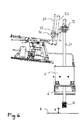
- die Spürvorrichtung gemäß
Fig.1 in der Luftspürstellung in einer Seitenansicht; - Fig. 7
- eine vergrößerte Darstellung der Handhabe zur Veranschaulichung der Veränderlichkeit der Winkelstellung.
- Die Darstellungen in
Fig. 1 und Fig. 2 zeigen ein militärisches Fahrzeug 1, welches als Spürfahrzeug ausgebildet ist. Im ballistisch geschützten Innenraum 7 des Fahrzeugs 1 ist ein Sitz 3 vorgesehen, von welchem aus eine im Folgenden als Spürer 2 bezeichnete Person eine Spürvorrichtung 9 des Fahrzeugs 1 bedienen kann. Die Darstellung inFig. 2 zeigt den Innenraum 7 des Fahrzeugs 1 in einer Draufsicht. Die Spürvorrichtung 9 ist derart neben dem Sitz 3 angeordnet, wie es von Feststellbremsen in Personenkraftfahrzeugen bekannt ist. - Die Spürvorrichtung 9 weist eine Ausrichtvorrichtung 10 auf, welche im Innenraum 7 des Fahrzeugs angeordnet ist und über welche ein Spürkopf 30 der Spürvorrichtung 9 über dem Erdboden ausgerichtet werden kann, vgl.
Fig. 3 und Fig. 4 . Wie derFig. 3 und Fig. 4 ferner zu entnehmen, ist der Spürkopf 30 am unteren Ende eine Rohres 31 angeordnet, welches durch einen Schacht 5 in der Fahrzeugbodenplatte 4 geführt ist. Der Spürkopf 30 weist einen Verdampfer auf, durch welchen Luft- oder Bodenproben in einen dampfförmigen Zustand überführt werden. Der Verdampfer ist nach Art eines Heizelements ausgebildet. - Das Rohr 31 dient dazu, durch den Spürkopf 30 verdampfte Luft- und/oder Bodenproben in das Innere des Fahrzeugs 1 zu leiten und einer nicht dargestellten Analysevorrichtung zuzuführen. Zum Schutz des Rohres 31 ist ein das Rohr 31 umgebender Faltenbalg 32 vorgesehen. Um zu vermeiden, dass durch Schad- oder Kampfstoffe kontaminierte Umgebungsluft in den Fahrzeuginnenraum 7 gelangen kann, ist der Schacht 5 zur Durchführung des Rohres 31 durch den Fahrzeugboden 4 derart flexibel abgedichtet, dass Ausricht- und Absenkbewegungen des Rohres 31 und des Spürkopfes 30 ermöglicht werden. Zur Lagerung des Rohres 31 im Fahrzeugboden 4 kann ein in den Figuren nicht dargestelltes Kugellager im Fahrzeugboden 4 oder in dem Schacht 5 vorgesehen sein.
- Um die Bodenfreiheit des Fahrzeugs 1 zu erhöhen, ist an der Spürvorrichtung 9 eine Höhenverstellvorrichtung 20 vorgesehen, welche zwischen der Ausrichtvorrichtung 10 und dem Spürkopf 30 angeordnet ist. Durch die Höhenverstellvorrichtung 20 kann der Hub des Spürkopfes 30 erhöht werden. Der Spürkopf 30 kann durch die Höhenverstellvorrichtung 10 von der Ruhestellung in die Spürstellung abgesenkt und von der Spürstellung in die Ruhestellung angehoben werden. Es ist daher nicht erforderlich, das Absenken des Spürkopfes 30 durch die Ausrichtvorrichtung 10 zu bewirken.
- Die Funktionsweise der erfindungsgemäßen Spürvorrichtung 9 und des Spürfahrzeugs 1 soll nachfolgend anhand der Detaildarstellungen in der
Fig. 5 undFig. 6 näher erläutert werden. - Die
Fig. 5 zeigt die Spürvorrichtung 9 in einer Ruhestellung, in welcher sich der Spürkopf 30 in einer vor Umwelteinflüssen geschützten Position innerhalb des Schachts 5 befindet. Um den Spürkopf 30 während des Fahrens mit dem Fahrzeug 1 vor ungewünschte Kontakt mit aus dem Boden 8 herausragenden Gegenständen zu schützen, sind die Klappen 6, welche den Schacht 5 nach unten hin abschließen, in der Ruhestellung geschlossen. - Zum Ausrichten des Spürkopfes 30 ist an der Spürvorrichtung 9 eine Ausrichtvorrichtung 10 vorgesehen, welche über eine Handhabe 11 bedienbar ist. Die Handhabe 11 ist nach Art einer im Wesentlichen länglichen Wippe ausgebildet, welche um ein Drehlager 13 in einer im wesentliche horizontalen Richtung verschwenkt werden kann. Die Handhabe 11 ist zusammen mit dem Drehlager 13 über ein zweites Drehlager 14 in einer im Wesentlichen wagerechten Ebene verschwenkbar. Die Drehachsen der Drehlager 13 und 14 sind senkrecht zueinander orientiert. Darüber hinaus weist die Ausrichtvorrichtung 10 eine Linearführung 15 auf, über welche die Handhabe 11 und die Drehlager 13 und 14 in Richtung einer Fahrzeuglängsachse L bewegt werden können.
- Um den Spürkopf 30 der Spürvorrichtung 9 von der in der
Fig. 5 dargestellten Ruhestellung in die in derFig. 6 dargestellte Luftspürstellung zu überführen, in welcher der Spürkopf 30 auf eine Höhe H über dem Erdboden 8 abgesenkt ist, ist an der Spürvorrichtung 9 ferner eine zwischen der Ausrichtvorrichtung 10 und dem Spürkopf 30 angeordnete Höhenverstellvorrichtung 20 vorgesehen. Durch die Höhenverstellvorrichtung 20 ist die Höhe H des Spürkopfes 30 frei wählbar, so dass ein beliebige Höhe H zwischen der Ruhestellung und einer Bodenspürstellung, in welcher der Spürkopf 30 in Kontakt mit dem Boden 8 steht, eingestellt werden kann. - Die Höhenverstellvorrichtung 20 ist starr mit der Ausrichtvorrichtung 10 verbunden und über einen als Kugelgelenk 33 ausgebildeten Gelenkpunkt mit dem Rohr 31 gekoppelt. Aufgrund der Anbindung der Höhenverstellvorrichtung 20 zwischen der Ausrichtvorrichtung 10 und dem Rohr 31, können Bewegungen der Ausrichtvorrichtung 10 auf Rohr 31 übertragen werden. Während die Höhe H des Spürkopfes über die Höhenverstellvorrichtung 20 eingestellt wird, kann somit die Ausrichtung des Spürkopfes 30 durch die Ausrichtvorrichtung 10 erfolgen. Wird die Ausrichtvorrichtung 10 beispielsweise, wie in der
Fig. 3 dargestellt, entlang der Linearführung 15 in Richtung des vorderen Endes des Fahrzeugsinnenraums 7 verschoben, so wird der Spürkopf 30 in dem Spürbereich über dem Boden 8 in eine entgegengesetzte Richtung ausgerichtet. Verschiebt der Spürer 2 die Ausrichtvorrichtung 10 in Richtung seines Rumpfes, so erfolgt eine Ausrichtung des Spürkopfes 30 in Richtung des in Fahrtrichtung vorderen Randes des Spürbereichs, vgl.Fig. 4 . - Unter dem Fahrzeug kann eine in den Figuren nicht dargestellte Kamera angeordnet sein, mittels derer das Ausrichten, das Absenken und das eigentliche Spüren über einen ebenfalls nicht dargestellten Monitor im Inneren 7 des Fahrzeugs 1 beobachtbar ist.
- Wie weiter der Darstellung in der
Fig. 5 zu entnehmen, weist die Höhenverstellvorrichtung 20 eine Gewindespindel 21 auf, auf welcher eine Spindelmutter 26 aufgenommen ist. Zum Schutz der Gewindespindel 21 ist ein Faltenbalg 22 vorgesehen, der die Gewindespindel 21 umgibt, vgl.Fig. 5 . Die Spindelmutter 26 ist über ein nach Art eines Lenkers ausgebildetes Verbindungsglied 24 mit dem Kugelgelenk 33 verbunden. Aus Stabilitätsgründen ist ferner eine Linearführung 23 zur Führung des Verbindungsglieds 24 in Richtung der Gewindespindel 21 vorgesehen, welche parallel zu der Gewindespindel 21 ausgerichtet ist. Das Verbindungsglied 24 weist hierzu ein Führungselement 27 auf, welches auf der Linearführung 23 geführt wird. Das Verbindungsglied 24 ist über das Kugelgelenk 33 schwenkbar mit dem Rohr 31 verbunden. - Die Betätigung der Gewindespindel 21 erfolgt über eine an der wippenförmigen Handhabe 11 der Ausrichtvorrichtung 10 angeordnete Kurbel 25, welche unabhängig von der Ausrichtvorrichtung 10 betätigbar ist. Über die Kurbel 25 kann die Position der Spindelmutter 26 auf der Gewindespindel 21 auf einfache Weise per Hand verändert werden und somit die Höhe H des Spürkopfes 30 eingestellt werden. Darüber hinaus ist die Gewindespindel 21 selbsthemmend ausgebildet, so dass die Spindelmutter 26 in einer beliebigen Position auf der Gewindespindel 21 angehalten werden kann, ohne Ihre Position von selbst zu verändern. Durch die selbsthemmende Gewindespindel 21 kann der Spürkopf 30 in einer Luftspürstellung in einer beliebigen Höhe H über dem Boden 8 arretiert werden.
- Anstelle einer Kurbel 25 kann an der Höhenverstellvorrichtung 20 ein Antrieb zur Betätigung der Gewindespindel 21 vorgesehen werden, so dass sich ein Linearantrieb nach Art eines Spindelantriebs ergibt. Ferner ist es auch denkbar, andere Linearantriebe, z. B. einen Hydraulikzylinder, einen Pneumatikzylinder oder einen elektromechanischen Linearantrieb zur Verstellung der Höhe H an der Höhenverstellvorrichtung 20 anzuordnen.
- Um eine Arretierung der Ausrichtung zu bewirken, weist die Ausrichtvorrichtung in den Drehlagern 13 und 14 sowie in der Linearführung 15 jeweils eine Bremse auf, welche über einen Bremshebel 12 betätigbar sind. Wie die Detaildarstellung der Handhabe 11 in der
Fig. 7 erkennen lässt, ist der Bremshebel 12 gelenkig an der Handhabe 11 angebunden und über eine Feder 16 gegen die Handhabe 11 vorgespannt. - Die Handhabe 11 weist zudem eine Griffschale 17 auf, in welcher die Hand des Spürers 2 beim Betätigen der Handhabe 11 aufgenommen werden kann. Um für Spürer 2 unterschiedlicher Größe optimale Arbeitsbedingungen zum Spüren zu schaffen, ist die Winkelstellung der Handhabe 11 verstellbar ausgebildet. Die Handhabe 11 weist einen Abschnitt 11.1 auf, welcher über eine Gelenk 18 schwenkbeweglich mit einem zweiten Abschnitt 11.2 verbunden ist. Durch halbkreisförmig angeordnete Öffnungen in den sich überlappenden Bereichen der Abschnitte 11.1 und 11.2 sind mehre Schrauben 19 zur Arretierung der Winkelstellung der der Abschnitte 11.1 und 11.2 zueinander geführt. In dem Ausführungsbeispiel gemäß
Fig. 7 sind drei verschiedene Winkelstellungen des Abschnittes 11.1 gegenüber dem Abschnitt 11.2 einstellbar. Der Abschnitt 11.1 kann gegenüber dem Abschnitt 11.2 um 0°, 20° sowie 40° verschwenkt werden. Alternativ könnte die Verstellung der beiden Abschnitte 11.1 und 11.2 derart ausgebildet sein, dass ein beliebiger Schwenkwinkel einstellbar ist. - Die vorstehend beschriebene Spürvorrichtung 9 kann bei dem Verfahren zum Bodenspüren aus dem Inneren 7 eines Fahrzeugs 1 zur Anwendung kommen. Gemäß den Verfahren wird der Spürkopf 30 der Spürvorrichtung 9 durch die Höhenverstellvorrichtung 20 in Richtung des Bodens 8 abgesenkt und durch die Ausrichtvorrichtung 10 in dem Spürbereich ausgerichtet. Das Ausrichten und Absenken kann manuell durch den Spürer 2 erfolgen.
- Sobald der Spürkopf 30 mit dem Erdboden 8 in Verbindung steht, kann über die Höhenverstellvorrichtung 20 ein ggf. erforderlicher Anpressdruck auf den Spürkopf 30 ausgeübt werden, indem die Kurbel 25 durch den Spürer 2 gedreht wird. Der Anpressdruck kann über die Höhenverstellvorrichtung 10 solange erhört werden, bis ein Spürergebnis erzielt wird. Während des Spürvorgangs wird eine Bodenprobe durch den Verdampfer des Spürkopfes 30 verdampft und durch das Rohr 31 zu der Analysevorrichtung im Inneren 7 des Fahrzeugs 1 eingesaugt.
- Optional kann die Spürvorrichtung 9 eine nicht dargestellte Sensorik aufweisen, die den Beginn und das Ende des Spürvorgangs detektiert. Beginn und Ende des Spürvorgangs können dem Spürer gemeldet werden. Zudem kann das Fahrzeug eine Steuervorrichtung aufweisen, über welche eine Fahrverblockung ermöglicht werden kann, die ein Anfahren verhindert, wenn sich die Spürvorrichtung in der Bodenspürstellung befindet.
- In Abwandlung des Ausführungsbeispiels kann der Spürkopf 30 mit dem Rohr 31 über ein Knickgelenk verbunden sein, so dass der Spürkopf 30 auf Unebenheiten des Bodens ausrichtbar ist. Das Knickgelenk kann federbelastet ausgestaltet sein.
- Die Geschwindigkeit beim Absenken des Spürkopfes 30 sowie die Anpresskraft kann über die Wahl der Übersetzung von der Kurbel 25 auf die Gewindespindel 21 eingestellt werden.
- Nachdem die Bodenspürung durchgeführt wurde, kann der Spürer 2 den Spürkopf durch die Höhenverstellvorrichtung 20 anheben und in die Ruhestellung überführen.
- Aufgrund der erfindungsgemäß zwischen der Ausrichtvorrichtung 10 und dem Spürkopf 30 angeordneten Höhenverstellvorrichtung 20 ermöglichen die beschriebene Spürvorrichtung 9, das Fahrzeug 1 und das Verfahren einen größeren Hub des Spürkopfes 30 und somit eine erhöhte Bodenfreiheit.
-
- 1
- Fahrzeug
- 2
- Person
- 3
- Sitz
- 4
- Fahrzeugbodenplatte
- 5
- Schacht
- 6
- Klappe
- 7
- Innenraum
- 8
- Boden
- 9
- Spürvorrichtung
- 10
- Ausrichtvorrichtung
- 11
- Handhabe
- 12
- Bremshebel
- 13
- Drehlager
- 14
- Drehlager
- 15
- Linearführung
- 16
- Feder
- 17
- Griffschale
- 18
- Gelenk
- 19
- Schrauben
- 20
- Höhenverstellvorrichtung
- 21
- Spindel
- 22
- Faltenbalg
- 23
- Führung
- 24
- Verbindungsglied
- 25
- Kurbel
- 26
- Spindelmutter
- 27
- Führungselement
- 30
- Spürkopf
- 31
- Rohr
- 32
- Faltenbalg
- 33
- Kugelgelenk
- H
- Höhe
- L
- Fahrzeuglängsachse
Claims (15)
- Spürvorrichtung für Bodenspürungen aus dem Inneren eines Fahrzeugs (1) mit einem mit dem Boden (8) in Kontakt bringbaren Spürkopf (30), der durch Betätigung einer Ausrichtvorrichtung (10) in einem Spürbereich über dem Boden (8) ausrichtbar ist,
gekennzeichnet durch
eine zwischen der Ausrichtvorrichtung (10) und dem Spürkopf (30) angeordnete Höhenverstellvorrichtung (20) zur Verstellung der Höhe (H) des Spürkopfes (30) über dem Boden (8). - Spürvorrichtung nach Anspruch 1, dadurch gekennzeichnet, dass die Höhenverstellvorrichtung (20) unabhängig von der Ausrichtvorrichtung (10) betätigbar ist.
- Spürvorrichtung nach einem der vorhergehenden Ansprüche, dadurch gekennzeichnet, dass die Höhenverstellvorrichtung (20) manuell und/oder motorisch betätigbar ist.
- Spürvorrichtung nach Anspruch 3, dadurch gekennzeichnet, dass die Höhenverstellvorrichtung (20) einen Linearantrieb aufweist.
- Spürvorrichtung nach einem der vorhergehenden Ansprüche, dadurch gekennzeichnet, dass die Höhenverstellvorrichtung (20) über eine Kurbel (25) bedienbar ist.
- Spürvorrichtung nach einem der vorhergehenden Ansprüche, dadurch gekennzeichnet, dass die Höhenverstellvorrichtung (20) eine Gewindespindel (21) aufweist.
- Spürvorrichtung nach Anspruch 6, dadurch gekennzeichnet, dass die Gewindespindel (21) selbsthemmend ausgebildet ist.
- Spürvorrichtung nach einem der vorhergehenden Ansprüche, dadurch gekennzeichnet, dass der Spürkopf (30) um einen Gelenkpunkt schwenkbar ist, wobei der Gelenkpunkt durch die Höhenverstellvorrichtung (20) absenkbar ist.
- Spürvorrichtung nach Anspruch 8, dadurch gekennzeichnet, dass der Gelenkpunkt als Kugelgelenk (33) ausgebildet ist.
- Spürvorrichtung nach einem der vorhergehenden Ansprüche, dadurch gekennzeichnet, dass die Höhenverstellvorrichtung (20) starr mit der Ausrichtvorrichtung (10) verbunden ist.
- Spürvorrichtung nach einem der vorhergehenden Ansprüche, dadurch gekennzeichnet, dass die Ausrichtvorrichtung (10) wippenförmig ausgebildet ist.
- Fahrzeug, gekennzeichnet durch eine Spürvorrichtung (9) nach einem der vorhergehenden Ansprüche.
- Verfahren zum Bodenspüren aus dem Inneren eines Fahrzeugs (1) mit einer Spürvorrichtung (9), die einen mit dem Boden (8) in Kontakt bringbaren Spürkopf (30) aufweist, der durch Betätigung einer Ausrichtvorrichtung (10) in einem Spürbereich über dem Boden (8) ausgerichtet wird,
dadurch gekennzeichnet,
dass der Spürkopf (30) über eine zwischen der Ausrichtvorrichtung (10) und dem Spürkopf (30) angeordnete Höhenverstellvorrichtung (20) abgesenkt wird. - Verfahren nach Anspruch 13, dadurch gekennzeichnet, dass die Spürvorrichtung nach einem der Ansprüche 1 bis 11 ausgebildet ist.
- Verfahren nach einem der Ansprüche 13 oder 14, dadurch gekennzeichnet, dass durch die Höhenverstellvorrichtung (20) ein Anpressdruck zum Anpressen des Spürkopfes (30) auf den Boden (8) ausgeübt wird.
Applications Claiming Priority (1)
| Application Number | Priority Date | Filing Date | Title |
|---|---|---|---|
| DE102011054436A DE102011054436A1 (de) | 2011-10-12 | 2011-10-12 | Spürvorrichtung für Bodenspürungen aus dem Inneren eines Fahrzeugs und Verfahren zum Bodenspüren |
Publications (4)
| Publication Number | Publication Date |
|---|---|
| EP2581698A2 true EP2581698A2 (de) | 2013-04-17 |
| EP2581698A3 EP2581698A3 (de) | 2015-01-14 |
| EP2581698B1 EP2581698B1 (de) | 2017-01-11 |
| EP2581698B2 EP2581698B2 (de) | 2025-07-09 |
Family
ID=46799156
Family Applications (1)
| Application Number | Title | Priority Date | Filing Date |
|---|---|---|---|
| EP12183350.3A Active EP2581698B2 (de) | 2011-10-12 | 2012-09-06 | Spürvorrichtung für Bodenspürungen aus dem Inneren eines Fahrzeugs und Verfahren zum Bodenspüren |
Country Status (2)
| Country | Link |
|---|---|
| EP (1) | EP2581698B2 (de) |
| DE (1) | DE102011054436A1 (de) |
Cited By (1)
| Publication number | Priority date | Publication date | Assignee | Title |
|---|---|---|---|---|
| CN112881082A (zh) * | 2021-01-18 | 2021-06-01 | 内蒙古京海煤矸石发电有限责任公司 | 基于ai视频技术的工业用微光环境下可视采样检测装置 |
Citations (1)
| Publication number | Priority date | Publication date | Assignee | Title |
|---|---|---|---|---|
| DE102009015828A1 (de) | 2009-04-01 | 2010-10-07 | Krauss-Maffei Wegmann Gmbh & Co. Kg | Spürvorrichtung für Bodenspürungen aus dem Inneren eines Fahrzeugs sowie Fahrzeug mit einer solchen Spürvorrichtung |
Family Cites Families (9)
| Publication number | Priority date | Publication date | Assignee | Title |
|---|---|---|---|---|
| DE3009069C2 (de) | 1980-03-10 | 1982-10-21 | Bundesrepublik Deutschland, Vertreten Durch Den Bundesminister Der Verteidigung, 5300 Bonn | Eingangs-Kopf eines Meß/Nachweissystems für chemische Agentien |
| DE4238399C1 (de) * | 1992-11-13 | 1994-03-24 | Bruker Franzen Analytik Gmbh | Mobiles Massenspektrometer mit einer Probenahmevorrichtung mit drehbarem Spürrad mit Metallfelge |
| US5435399A (en) * | 1994-07-05 | 1995-07-25 | Concord, Inc. | Soil sampler |
| DE19712420C1 (de) * | 1997-03-25 | 1998-09-10 | Stefan Kettner | Vorrichtung zur automatisierten Entnahme von Feststoffproben mit einem Bohrstock |
| DE29910714U1 (de) * | 1999-06-18 | 2000-05-25 | Georg Fritzmeier GmbH & Co., 85655 Großhelfendorf | Bodenprobenentnahmegerät |
| ATE326654T1 (de) | 2003-03-19 | 2006-06-15 | Skf Ab | Sicherheitsmutter und aufnahmeteil für eine sicherheitsmutter für einen linearantrieb |
| DE102009010083A1 (de) | 2009-02-21 | 2010-09-02 | Rheinmetall Landsysteme Gmbh | Fernsteuerbare Spürradabwurf- und -wechselvorrichtung sowie Verwendung an einem Fahrzeug oder Objekt |
| DE102009010082B4 (de) * | 2009-02-21 | 2016-04-21 | Rheinmetall Landsysteme Gmbh | Sondenhalterung für ein Fahrzeug bzw. Objekt |
| DE102009020700A1 (de) * | 2009-05-11 | 2010-11-18 | Rheinmetall Landsysteme Gmbh | Radspürgerät für einen ABC-Einsatz |
-
2011
- 2011-10-12 DE DE102011054436A patent/DE102011054436A1/de active Pending
-
2012
- 2012-09-06 EP EP12183350.3A patent/EP2581698B2/de active Active
Patent Citations (1)
| Publication number | Priority date | Publication date | Assignee | Title |
|---|---|---|---|---|
| DE102009015828A1 (de) | 2009-04-01 | 2010-10-07 | Krauss-Maffei Wegmann Gmbh & Co. Kg | Spürvorrichtung für Bodenspürungen aus dem Inneren eines Fahrzeugs sowie Fahrzeug mit einer solchen Spürvorrichtung |
Cited By (1)
| Publication number | Priority date | Publication date | Assignee | Title |
|---|---|---|---|---|
| CN112881082A (zh) * | 2021-01-18 | 2021-06-01 | 内蒙古京海煤矸石发电有限责任公司 | 基于ai视频技术的工业用微光环境下可视采样检测装置 |
Also Published As
| Publication number | Publication date |
|---|---|
| EP2581698B1 (de) | 2017-01-11 |
| EP2581698A3 (de) | 2015-01-14 |
| DE102011054436A1 (de) | 2013-04-18 |
| EP2581698B2 (de) | 2025-07-09 |
Similar Documents
| Publication | Publication Date | Title |
|---|---|---|
| EP0900313B1 (de) | Vorrichtung zum öffnen und verschliessen einer schiebetür, insbesondere für fahrzeuge | |
| WO2019115065A1 (de) | Türgriffanordnung einer fahrzeugtür | |
| WO1997034793A1 (de) | Seitenwand für den aufbau eines fahrzeuges | |
| DE102008057880A1 (de) | Vorrichtung zur Verstellung einer Klappe für ein Kraftfahrzeug | |
| DE102018214183A1 (de) | Fahrzeug mit entlang verschiedener Verstellbahnen verstellbarer Fahrzeugtür | |
| EP2365171A2 (de) | Lagerung einer Klappe an einem Aufbau eines Kraftwagens sowie Karosserie für einen solchen Kraftwagen | |
| DE102004003956B4 (de) | Heckklappe eines Kraftfahrzeugs | |
| EP0716004A1 (de) | Schwenkschiebetür für Fahrzeuge zur Personenbeförderung | |
| DE102007027859A1 (de) | Abdeckung für eine Gestängeaustrittsöffnung | |
| EP2581698B1 (de) | Spürvorrichtung für Bodenspürungen aus dem Inneren eines Fahrzeugs und Verfahren zum Bodenspüren | |
| DE102011116174B4 (de) | Anordnung zur Befestigung zumindest einer Hecktür an einer Karosserie eines Fahrzeugs sowie Fahrzeug mit einer derartigen Anordnung | |
| EP3512760B1 (de) | Luftwiderstandsreduzierende vorrichtung für ein fahrzeug | |
| DE10025888B4 (de) | Seitentür eines Kraftfahrzeugs | |
| EP2435813B1 (de) | Spürvorrichtung für bodenspürungen aus dem inneren eines fahrzeugs sowie fahrzeug mit einer solchen spürvorrichtung | |
| EP1418116A2 (de) | Verfahren und Vorrichtung zur Schliesskeilsimulation | |
| DE10117769A1 (de) | Vorrichtung zur Unterstützung einer Öffnungsbewegung einer Fahrzeugklappe | |
| DE102019123442A1 (de) | Bedieneinheit mit bedarfsweise motorisch versenkbarem und dabei motorisch abdeckbarem Betätigungsteil | |
| DE102016107292B4 (de) | Strömungsleitelement | |
| DE102005057586B4 (de) | PKW-Tür | |
| DE10131052B4 (de) | Abdeckklappe für ein Fahrzeug | |
| DE10033026B4 (de) | Seitentür eines Kraftfahrzeugs | |
| DE10218885A1 (de) | Hardtop-Fahrzeugdach | |
| DE102018211256B4 (de) | Türantrieb für eine Kraftwagentür sowie Halteanordnung | |
| DE102006043817A1 (de) | Bewegungsmechanismus für eine Stauraumklappe eines Omnibusses | |
| WO2006128440A2 (de) | Tür mit türbremse |
Legal Events
| Date | Code | Title | Description |
|---|---|---|---|
| PUAI | Public reference made under article 153(3) epc to a published international application that has entered the european phase |
Free format text: ORIGINAL CODE: 0009012 |
|
| AK | Designated contracting states |
Kind code of ref document: A2 Designated state(s): AL AT BE BG CH CY CZ DE DK EE ES FI FR GB GR HR HU IE IS IT LI LT LU LV MC MK MT NL NO PL PT RO RS SE SI SK SM TR |
|
| AX | Request for extension of the european patent |
Extension state: BA ME |
|
| PUAL | Search report despatched |
Free format text: ORIGINAL CODE: 0009013 |
|
| AK | Designated contracting states |
Kind code of ref document: A3 Designated state(s): AL AT BE BG CH CY CZ DE DK EE ES FI FR GB GR HR HU IE IS IT LI LT LU LV MC MK MT NL NO PL PT RO RS SE SI SK SM TR |
|
| AX | Request for extension of the european patent |
Extension state: BA ME |
|
| RIC1 | Information provided on ipc code assigned before grant |
Ipc: F41H 7/02 20060101ALN20141209BHEP Ipc: F41H 7/03 20060101AFI20141209BHEP |
|
| 17P | Request for examination filed |
Effective date: 20150624 |
|
| RBV | Designated contracting states (corrected) |
Designated state(s): AL AT BE BG CH CY CZ DE DK EE ES FI FR GB GR HR HU IE IS IT LI LT LU LV MC MK MT NL NO PL PT RO RS SE SI SK SM TR |
|
| RIC1 | Information provided on ipc code assigned before grant |
Ipc: F41H 7/03 20060101AFI20160404BHEP Ipc: F41H 7/02 20060101ALN20160404BHEP |
|
| 17Q | First examination report despatched |
Effective date: 20160428 |
|
| GRAP | Despatch of communication of intention to grant a patent |
Free format text: ORIGINAL CODE: EPIDOSNIGR1 |
|
| RIC1 | Information provided on ipc code assigned before grant |
Ipc: F41H 7/03 20060101AFI20161003BHEP Ipc: F41H 7/02 20060101ALN20161003BHEP |
|
| RIC1 | Information provided on ipc code assigned before grant |
Ipc: F41H 7/02 20060101ALN20161013BHEP Ipc: F41H 7/03 20060101AFI20161013BHEP |
|
| INTG | Intention to grant announced |
Effective date: 20161028 |
|
| RIC1 | Information provided on ipc code assigned before grant |
Ipc: F41H 7/02 20060101ALN20161020BHEP Ipc: F41H 7/03 20060101AFI20161020BHEP |
|
| GRAS | Grant fee paid |
Free format text: ORIGINAL CODE: EPIDOSNIGR3 |
|
| STAA | Information on the status of an ep patent application or granted ep patent |
Free format text: STATUS: GRANT OF PATENT IS INTENDED |
|
| GRAA | (expected) grant |
Free format text: ORIGINAL CODE: 0009210 |
|
| STAA | Information on the status of an ep patent application or granted ep patent |
Free format text: STATUS: THE PATENT HAS BEEN GRANTED |
|
| AK | Designated contracting states |
Kind code of ref document: B1 Designated state(s): AL AT BE BG CH CY CZ DE DK EE ES FI FR GB GR HR HU IE IS IT LI LT LU LV MC MK MT NL NO PL PT RO RS SE SI SK SM TR |
|
| REG | Reference to a national code |
Ref country code: GB Ref legal event code: FG4D Free format text: NOT ENGLISH |
|
| REG | Reference to a national code |
Ref country code: CH Ref legal event code: EP |
|
| REG | Reference to a national code |
Ref country code: AT Ref legal event code: REF Ref document number: 861702 Country of ref document: AT Kind code of ref document: T Effective date: 20170115 |
|
| REG | Reference to a national code |
Ref country code: IE Ref legal event code: FG4D Free format text: LANGUAGE OF EP DOCUMENT: GERMAN |
|
| REG | Reference to a national code |
Ref country code: DE Ref legal event code: R096 Ref document number: 502012009273 Country of ref document: DE |
|
| REG | Reference to a national code |
Ref country code: LT Ref legal event code: MG4D |
|
| REG | Reference to a national code |
Ref country code: NL Ref legal event code: MP Effective date: 20170111 |
|
| PG25 | Lapsed in a contracting state [announced via postgrant information from national office to epo] |
Ref country code: NL Free format text: LAPSE BECAUSE OF FAILURE TO SUBMIT A TRANSLATION OF THE DESCRIPTION OR TO PAY THE FEE WITHIN THE PRESCRIBED TIME-LIMIT Effective date: 20170111 |
|
| PG25 | Lapsed in a contracting state [announced via postgrant information from national office to epo] |
Ref country code: GR Free format text: LAPSE BECAUSE OF FAILURE TO SUBMIT A TRANSLATION OF THE DESCRIPTION OR TO PAY THE FEE WITHIN THE PRESCRIBED TIME-LIMIT Effective date: 20170412 Ref country code: NO Free format text: LAPSE BECAUSE OF FAILURE TO SUBMIT A TRANSLATION OF THE DESCRIPTION OR TO PAY THE FEE WITHIN THE PRESCRIBED TIME-LIMIT Effective date: 20170411 Ref country code: HR Free format text: LAPSE BECAUSE OF FAILURE TO SUBMIT A TRANSLATION OF THE DESCRIPTION OR TO PAY THE FEE WITHIN THE PRESCRIBED TIME-LIMIT Effective date: 20170111 Ref country code: FI Free format text: LAPSE BECAUSE OF FAILURE TO SUBMIT A TRANSLATION OF THE DESCRIPTION OR TO PAY THE FEE WITHIN THE PRESCRIBED TIME-LIMIT Effective date: 20170111 Ref country code: LT Free format text: LAPSE BECAUSE OF FAILURE TO SUBMIT A TRANSLATION OF THE DESCRIPTION OR TO PAY THE FEE WITHIN THE PRESCRIBED TIME-LIMIT Effective date: 20170111 Ref country code: IS Free format text: LAPSE BECAUSE OF FAILURE TO SUBMIT A TRANSLATION OF THE DESCRIPTION OR TO PAY THE FEE WITHIN THE PRESCRIBED TIME-LIMIT Effective date: 20170511 |
|
| PG25 | Lapsed in a contracting state [announced via postgrant information from national office to epo] |
Ref country code: RS Free format text: LAPSE BECAUSE OF FAILURE TO SUBMIT A TRANSLATION OF THE DESCRIPTION OR TO PAY THE FEE WITHIN THE PRESCRIBED TIME-LIMIT Effective date: 20170111 Ref country code: PT Free format text: LAPSE BECAUSE OF FAILURE TO SUBMIT A TRANSLATION OF THE DESCRIPTION OR TO PAY THE FEE WITHIN THE PRESCRIBED TIME-LIMIT Effective date: 20170511 Ref country code: BG Free format text: LAPSE BECAUSE OF FAILURE TO SUBMIT A TRANSLATION OF THE DESCRIPTION OR TO PAY THE FEE WITHIN THE PRESCRIBED TIME-LIMIT Effective date: 20170411 Ref country code: PL Free format text: LAPSE BECAUSE OF FAILURE TO SUBMIT A TRANSLATION OF THE DESCRIPTION OR TO PAY THE FEE WITHIN THE PRESCRIBED TIME-LIMIT Effective date: 20170111 Ref country code: LV Free format text: LAPSE BECAUSE OF FAILURE TO SUBMIT A TRANSLATION OF THE DESCRIPTION OR TO PAY THE FEE WITHIN THE PRESCRIBED TIME-LIMIT Effective date: 20170111 Ref country code: ES Free format text: LAPSE BECAUSE OF FAILURE TO SUBMIT A TRANSLATION OF THE DESCRIPTION OR TO PAY THE FEE WITHIN THE PRESCRIBED TIME-LIMIT Effective date: 20170111 Ref country code: SE Free format text: LAPSE BECAUSE OF FAILURE TO SUBMIT A TRANSLATION OF THE DESCRIPTION OR TO PAY THE FEE WITHIN THE PRESCRIBED TIME-LIMIT Effective date: 20170111 |
|
| REG | Reference to a national code |
Ref country code: FR Ref legal event code: PLFP Year of fee payment: 6 |
|
| REG | Reference to a national code |
Ref country code: DE Ref legal event code: R026 Ref document number: 502012009273 Country of ref document: DE |
|
| PLBI | Opposition filed |
Free format text: ORIGINAL CODE: 0009260 |
|
| PG25 | Lapsed in a contracting state [announced via postgrant information from national office to epo] |
Ref country code: SK Free format text: LAPSE BECAUSE OF FAILURE TO SUBMIT A TRANSLATION OF THE DESCRIPTION OR TO PAY THE FEE WITHIN THE PRESCRIBED TIME-LIMIT Effective date: 20170111 Ref country code: EE Free format text: LAPSE BECAUSE OF FAILURE TO SUBMIT A TRANSLATION OF THE DESCRIPTION OR TO PAY THE FEE WITHIN THE PRESCRIBED TIME-LIMIT Effective date: 20170111 Ref country code: RO Free format text: LAPSE BECAUSE OF FAILURE TO SUBMIT A TRANSLATION OF THE DESCRIPTION OR TO PAY THE FEE WITHIN THE PRESCRIBED TIME-LIMIT Effective date: 20170111 |
|
| PLAX | Notice of opposition and request to file observation + time limit sent |
Free format text: ORIGINAL CODE: EPIDOSNOBS2 |
|
| 26 | Opposition filed |
Opponent name: RHEINMETALL MAN MILITARY VEHICLES GMBH Effective date: 20171011 |
|
| PG25 | Lapsed in a contracting state [announced via postgrant information from national office to epo] |
Ref country code: SM Free format text: LAPSE BECAUSE OF FAILURE TO SUBMIT A TRANSLATION OF THE DESCRIPTION OR TO PAY THE FEE WITHIN THE PRESCRIBED TIME-LIMIT Effective date: 20170111 Ref country code: DK Free format text: LAPSE BECAUSE OF FAILURE TO SUBMIT A TRANSLATION OF THE DESCRIPTION OR TO PAY THE FEE WITHIN THE PRESCRIBED TIME-LIMIT Effective date: 20170111 |
|
| PLBB | Reply of patent proprietor to notice(s) of opposition received |
Free format text: ORIGINAL CODE: EPIDOSNOBS3 |
|
| PG25 | Lapsed in a contracting state [announced via postgrant information from national office to epo] |
Ref country code: SI Free format text: LAPSE BECAUSE OF FAILURE TO SUBMIT A TRANSLATION OF THE DESCRIPTION OR TO PAY THE FEE WITHIN THE PRESCRIBED TIME-LIMIT Effective date: 20170111 |
|
| REG | Reference to a national code |
Ref country code: CH Ref legal event code: PL |
|
| PG25 | Lapsed in a contracting state [announced via postgrant information from national office to epo] |
Ref country code: MC Free format text: LAPSE BECAUSE OF FAILURE TO SUBMIT A TRANSLATION OF THE DESCRIPTION OR TO PAY THE FEE WITHIN THE PRESCRIBED TIME-LIMIT Effective date: 20170111 |
|
| REG | Reference to a national code |
Ref country code: IE Ref legal event code: MM4A |
|
| REG | Reference to a national code |
Ref country code: BE Ref legal event code: MM Effective date: 20170930 |
|
| PG25 | Lapsed in a contracting state [announced via postgrant information from national office to epo] |
Ref country code: LU Free format text: LAPSE BECAUSE OF NON-PAYMENT OF DUE FEES Effective date: 20170906 |
|
| PG25 | Lapsed in a contracting state [announced via postgrant information from national office to epo] |
Ref country code: IE Free format text: LAPSE BECAUSE OF NON-PAYMENT OF DUE FEES Effective date: 20170906 Ref country code: CH Free format text: LAPSE BECAUSE OF NON-PAYMENT OF DUE FEES Effective date: 20170930 Ref country code: LI Free format text: LAPSE BECAUSE OF NON-PAYMENT OF DUE FEES Effective date: 20170930 |
|
| PG25 | Lapsed in a contracting state [announced via postgrant information from national office to epo] |
Ref country code: BE Free format text: LAPSE BECAUSE OF NON-PAYMENT OF DUE FEES Effective date: 20170930 |
|
| REG | Reference to a national code |
Ref country code: FR Ref legal event code: PLFP Year of fee payment: 7 |
|
| PG25 | Lapsed in a contracting state [announced via postgrant information from national office to epo] |
Ref country code: MT Free format text: LAPSE BECAUSE OF FAILURE TO SUBMIT A TRANSLATION OF THE DESCRIPTION OR TO PAY THE FEE WITHIN THE PRESCRIBED TIME-LIMIT Effective date: 20170111 |
|
| REG | Reference to a national code |
Ref country code: AT Ref legal event code: MM01 Ref document number: 861702 Country of ref document: AT Kind code of ref document: T Effective date: 20170906 |
|
| PG25 | Lapsed in a contracting state [announced via postgrant information from national office to epo] |
Ref country code: AT Free format text: LAPSE BECAUSE OF NON-PAYMENT OF DUE FEES Effective date: 20170906 |
|
| RDAF | Communication despatched that patent is revoked |
Free format text: ORIGINAL CODE: EPIDOSNREV1 |
|
| APBM | Appeal reference recorded |
Free format text: ORIGINAL CODE: EPIDOSNREFNO |
|
| APBP | Date of receipt of notice of appeal recorded |
Free format text: ORIGINAL CODE: EPIDOSNNOA2O |
|
| APAH | Appeal reference modified |
Free format text: ORIGINAL CODE: EPIDOSCREFNO |
|
| PG25 | Lapsed in a contracting state [announced via postgrant information from national office to epo] |
Ref country code: HU Free format text: LAPSE BECAUSE OF FAILURE TO SUBMIT A TRANSLATION OF THE DESCRIPTION OR TO PAY THE FEE WITHIN THE PRESCRIBED TIME-LIMIT; INVALID AB INITIO Effective date: 20120906 |
|
| APBQ | Date of receipt of statement of grounds of appeal recorded |
Free format text: ORIGINAL CODE: EPIDOSNNOA3O |
|
| PG25 | Lapsed in a contracting state [announced via postgrant information from national office to epo] |
Ref country code: CY Free format text: LAPSE BECAUSE OF NON-PAYMENT OF DUE FEES Effective date: 20170111 |
|
| PG25 | Lapsed in a contracting state [announced via postgrant information from national office to epo] |
Ref country code: MK Free format text: LAPSE BECAUSE OF FAILURE TO SUBMIT A TRANSLATION OF THE DESCRIPTION OR TO PAY THE FEE WITHIN THE PRESCRIBED TIME-LIMIT Effective date: 20170111 |
|
| PG25 | Lapsed in a contracting state [announced via postgrant information from national office to epo] |
Ref country code: TR Free format text: LAPSE BECAUSE OF FAILURE TO SUBMIT A TRANSLATION OF THE DESCRIPTION OR TO PAY THE FEE WITHIN THE PRESCRIBED TIME-LIMIT Effective date: 20170111 |
|
| PG25 | Lapsed in a contracting state [announced via postgrant information from national office to epo] |
Ref country code: AL Free format text: LAPSE BECAUSE OF FAILURE TO SUBMIT A TRANSLATION OF THE DESCRIPTION OR TO PAY THE FEE WITHIN THE PRESCRIBED TIME-LIMIT Effective date: 20170111 |
|
| APAH | Appeal reference modified |
Free format text: ORIGINAL CODE: EPIDOSCREFNO |
|
| APBU | Appeal procedure closed |
Free format text: ORIGINAL CODE: EPIDOSNNOA9O |
|
| PLAY | Examination report in opposition despatched + time limit |
Free format text: ORIGINAL CODE: EPIDOSNORE2 |
|
| P01 | Opt-out of the competence of the unified patent court (upc) registered |
Effective date: 20230517 |
|
| PLBC | Reply to examination report in opposition received |
Free format text: ORIGINAL CODE: EPIDOSNORE3 |
|
| PLAY | Examination report in opposition despatched + time limit |
Free format text: ORIGINAL CODE: EPIDOSNORE2 |
|
| PLBC | Reply to examination report in opposition received |
Free format text: ORIGINAL CODE: EPIDOSNORE3 |
|
| REG | Reference to a national code |
Ref country code: DE Ref legal event code: R081 Ref document number: 502012009273 Country of ref document: DE Owner name: KNDS DEUTSCHLAND GMBH & CO. KG, DE Free format text: FORMER OWNER: KRAUSS-MAFFEI WEGMANN GMBH & CO. KG, 80997 MUENCHEN, DE |
|
| RAP4 | Party data changed (patent owner data changed or rights of a patent transferred) |
Owner name: KNDS DEUTSCHLAND GMBH & CO. KG |
|
| PUAH | Patent maintained in amended form |
Free format text: ORIGINAL CODE: 0009272 |
|
| STAA | Information on the status of an ep patent application or granted ep patent |
Free format text: STATUS: PATENT MAINTAINED AS AMENDED |
|
| 27A | Patent maintained in amended form |
Effective date: 20250709 |
|
| AK | Designated contracting states |
Kind code of ref document: B2 Designated state(s): AL AT BE BG CH CY CZ DE DK EE ES FI FR GB GR HR HU IE IS IT LI LT LU LV MC MK MT NL NO PL PT RO RS SE SI SK SM TR |
|
| REG | Reference to a national code |
Ref country code: DE Ref legal event code: R102 Ref document number: 502012009273 Country of ref document: DE |
|
| PGFP | Annual fee paid to national office [announced via postgrant information from national office to epo] |
Ref country code: DE Payment date: 20250930 Year of fee payment: 14 |
|
| PGFP | Annual fee paid to national office [announced via postgrant information from national office to epo] |
Ref country code: GB Payment date: 20250923 Year of fee payment: 14 |
|
| PGFP | Annual fee paid to national office [announced via postgrant information from national office to epo] |
Ref country code: FR Payment date: 20250922 Year of fee payment: 14 |
|
| PGFP | Annual fee paid to national office [announced via postgrant information from national office to epo] |
Ref country code: CZ Payment date: 20250827 Year of fee payment: 14 |
|
| PGFP | Annual fee paid to national office [announced via postgrant information from national office to epo] |
Ref country code: IT Payment date: 20250930 Year of fee payment: 14 |