EP2581532A2 - Eckumlenkung für einen Treibstangenbeschlag eines Fensters - Google Patents
Eckumlenkung für einen Treibstangenbeschlag eines Fensters Download PDFInfo
- Publication number
- EP2581532A2 EP2581532A2 EP12187656.9A EP12187656A EP2581532A2 EP 2581532 A2 EP2581532 A2 EP 2581532A2 EP 12187656 A EP12187656 A EP 12187656A EP 2581532 A2 EP2581532 A2 EP 2581532A2
- Authority
- EP
- European Patent Office
- Prior art keywords
- housing
- blocking element
- drive rod
- blocking
- latching
- Prior art date
- Legal status (The legal status is an assumption and is not a legal conclusion. Google has not performed a legal analysis and makes no representation as to the accuracy of the status listed.)
- Granted
Links
Images


Classifications
-
- E—FIXED CONSTRUCTIONS
- E05—LOCKS; KEYS; WINDOW OR DOOR FITTINGS; SAFES
- E05C—BOLTS OR FASTENING DEVICES FOR WINGS, SPECIALLY FOR DOORS OR WINDOWS
- E05C9/00—Arrangements of simultaneously actuated bolts or other securing devices at well-separated positions on the same wing
- E05C9/24—Means for transmitting movements between vertical and horizontal sliding bars, rods or cables for the fastening of wings, e.g. corner guides
-
- E—FIXED CONSTRUCTIONS
- E05—LOCKS; KEYS; WINDOW OR DOOR FITTINGS; SAFES
- E05F—DEVICES FOR MOVING WINGS INTO OPEN OR CLOSED POSITION; CHECKS FOR WINGS; WING FITTINGS NOT OTHERWISE PROVIDED FOR, CONCERNED WITH THE FUNCTIONING OF THE WING
- E05F7/00—Accessories for wings not provided for in other groups of this subclass
- E05F7/08—Means for transmitting movements between vertical and horizontal sliding bars, rods, or cables
Definitions
- the invention relates to a Eckumlenkung for an espagnolette fitting a window, a French window or the like with a flexible, mounted in a two housing leg housing deflecting member, fixed to the ends of the deflector espagnolette sections and with a fixed to the housing, a latch hook-retaining tongue for mounting of the housing in a fitting groove of the window, the French window or the like, wherein on the side facing away from the latching hook side of the latching tongue, a blocking element is arranged, which from a release position in which the latching tongue is freely movable, in a blocking position in which the movement of the latching hook is blocked, is transferable.
- Such Eckumlenkung is for example from the DE 20 15 723 C3 known.
- This corner drive has a pin or a screw as a separately mounted blocking element.
- the pin or screw is mounted on the latching hook side facing away from the latching tongue and prevents the latching tongue is pushed back. Thus, the latching hook is blocked in a position in which the Eckumlenkung is held on the window.
- the disadvantage of this Eckumlenkung is that the separate assembly of pins or screws require a very high construction cost, especially with multiple locking hooks. Often corner deflections are held with eight locking hooks. Therefore, then the assembly of eight pins or screws is required.
- the invention is based on the problem, a corner drive of the type mentioned so on to form that it is very simple and that the locking hooks can be blocked as easily as possible in their movement.
- the respective, the latching hook having housing leg of the housing has a guide for the blocking element, that the guide is arranged parallel to the drive rod section and that the blocking element is displaceably guided in the guide.
- the blocking element is held in the guide and can therefore be mounted with the Eckumlenkung in the fitting in the window. Subsequently, the blocking element is moved, thus blocking the movement of the locking hooks.
- the Eckumlenkung invention is particularly simple.
- the blocking element preferably has insertion bevels.
- the latching hook can be according to another advantageous embodiment of the invention easily block either or release if the blocking element is a separate, independent of the deflecting member movable component.
- the blocking element can be according to another advantageous development easily move between the blocking position and the release position when the housing has an opening for the implementation of a tool in the range of movement of the blocking element.
- Unintentional removal of the blocking element from the blocking position can be reliably avoided according to another advantageous embodiment of the invention, when the blocking element formed as a separate component is held by clamping means or by locking means in the blocking position.
- the clamping means could be for example a press fit.
- the latching means could be formed as resilient, biased by or against the blocking element latching elements.
- the corner drive according to the invention has a particularly small number of components, if at least one of the drive rod sections is designed as a blocking element.
- the latching tongue is blocked in a position of the drive rod section and released in another position. Therefore, in the mounted state of the corner drive, the release position can be set to a locking position of the drive rod fitting.
- the blocking position of the blocking element can be placed on the other positions of the espagnolette fitting, in which the corner drive is accessible from the outside.
- the protruding into the housing end of the drive rod section could control the release or blocking of the latching tongue.
- the release position can be according to another advantageous embodiment of the invention simply put on the intended position of the espagnolette, if the at least a drive rod section has a recess for receiving the latching tongue in the release position.
- the use of tools for moving the blocking element into the blocking position can be easily avoided if the position of the blocking element is controllable from the position of the next drive rod section such that in the end position of the drive rod section, the blocking element is in the blocking position.
- the corner drive according to the invention can be easily inserted into the fitting groove and move the drive rod section in the end position. In this case, the blocking element is moved, so that the corner drive is fixed in the fitting groove. Tool is therefore required only for improbable disassembly of the corner drive.
- the guide is designed in the housing for guiding both components of the blocking element and the drive rod section.
- the housing has a base for covering the fitting groove and protruding into the fitting groove legs and if two locking tongues are formed opposite each other of sections of the legs.
- FIG. 1 shows a window with a pivotable against a frame 1 wings 2 and with a espagnolette fitting 3.
- the espagnolette fitting 3 has a drive rod 4 driven by a drive rod 5 and a corner 6 for deflecting the movement of the drive rod 5.
- About the drive rod 5 are several closures. 7 driven.
- FIG. 2 shows enlarged sectional view along the line II - II through a portion of the wing 2 from FIG. 1 with the Eckumlenkung 6 and a displaceable perpendicular to the plane of the drive rod 5.
- the corner drive 6 is locked in a fitting groove 8 of the wing 2 at two paragraphs 9.
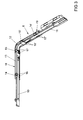
- FIG. 3 shows in perspective the corner drive 6 FIG. 1 ,
- the corner drive 6 has two drive rod sections 10, 11, which are connected to each other via a concealed in a sheet guide 12 deflection. Furthermore, the corner drive 6 has a made of plastic housing 13 with arranged thereon locking tongues 14, 15 with latching hooks 16, 17.
- the latching hooks 16, 17 each serve for latching with the in FIG. 2
- the corner drive 6 has two housing legs 18, 19, wherein arranged thereon latching tongues 14, 14 '15, 15' and latching hooks 16, 16 ', 17, 17' are each constructed the same.
- FIG. 4 shows enlarged one of the housing leg 18 of the corner 6 from FIG. 3 ,
- the latching tongues 14, 15 are arranged transversely to the direction of movement of the drive rod section 10 guided in this housing leg 18.
- the latching hooks 16, 17 can be pivoted into the housing 13, thereby elastically deforming the latching tongues 14, 15.
- the corner drive 6 in the in FIG. 2 shown fitting groove 8 are mounted by simply pushing.
- the latching hooks 16, 17 engage behind the heels 9.
- the Eckumlenkung 6 also has in a common guide 20 with the drive rod portion 10 sliding blocking elements 21, 22.
- One of the blocking elements 22 is arranged freely displaceable in the guide 20 of the housing 13 and can be behind the one locking tongues 15 lead.
- this blocking element 22 is held in the guide 20 in a force-fit manner.
- the other of the blocking elements 21 is fastened to the drive rod section 10.
- the blocking element 21 has for this purpose a recess 23 for receiving the locking tongues 14 during assembly of the corner deflection 6 in the fitting groove 8.
- the recess 23 can be moved out of the pivoting region of the locking tongues 14, so that the locking tongues 14 are blocked.
- the latching hooks 16 can not be pressed into the housing 13.
- the movement of the other blocking element 22 can by means of of the drive rod portion 10 or the housing 13 has a concealed in this view opening for performing a tool.
- the housing 13 is designed in cross-section U-shaped with a base 24 for covering the fitting groove 8 FIG. 2 and in the fitting groove 8 projecting legs 25.
- the locking tongues 14 ', 15 are generated by subdivision of the legs 25.
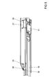
- FIG. 5 shows a further embodiment of the corner drive 6 with a plurality of latching tongues 26, 27 arranged latching hooks 28, 29 for engaging behind the heels 9 of the fitting groove 8 FIG. 1 ,
- the locking tongues 26, 27 are each shown here in the blocking position of blocking elements 30, 31.
- At the free end of the housing 13 of the Eckumlenkung 6 arranged locking tongues 26 are arranged parallel to the direction of movement of the espagnolette fitting 3. Otherwise, this embodiment of the corner drive 6 as the off FIG. 4 built up.
Landscapes
- Engineering & Computer Science (AREA)
- Mechanical Engineering (AREA)
- Power-Operated Mechanisms For Wings (AREA)
- Window Of Vehicle (AREA)
- Joining Of Corner Units Of Frames Or Wings (AREA)
- Casings For Electric Apparatus (AREA)
Abstract
Description
- Die Erfindung betrifft eine Eckumlenkung für einen Treibstangenbeschlag eines Fensters, einer Fenstertür oder dergleichen mit einem biegsamen, in einem zwei Gehäuseschenkel aufweisenden Gehäuse montierten Umlenkglied, mit an den Enden des Umlenkgliedes befestigten Treibstangenabschnitten und mit einer an dem Gehäuse befestigten, einen Rasthaken halternden Rastzunge zur Befestigung des Gehäuses in einer Beschlagnut des Fensters, der Fenstertür oder dergleichen, wobei an der den Rasthaken abgewandten Seite der Rastzunge ein Blockierelement angeordnet ist, welches von einer Freigabestellung, in der die Rastzunge frei beweglich ist, in eine Blockierstellung, in der die Bewegung der Rasthaken blockiert ist, überführbar ist.
- Eine solche Eckumlenkung ist beispielsweise aus der
DE 20 15 723 C3 bekannt. Diese Eckumlenkung weist einen Stift oder eine Schraube als separat zu montierendes Blockierelement auf. Der Stift oder die Schraube wird auf der dem Rasthaken abgewandten Seite der Rastzunge montiert und verhindert, dass die Rastzunge zurückgedrückt wird. Damit ist der Rasthaken in einer Stellung blockiert, in der die Eckumlenkung an dem Fenster gehalten ist. Nachteilig bei dieser Eckumlenkung ist jedoch, dass die separate Montage von Stiften oder Schrauben insbesondere bei mehreren Rasthaken einen sehr hohen baulichen Aufwand erfordern. Häufig sind Eckumlenkungen mit acht Rasthaken gehalten. Daher ist dann auch die Montage von acht Stiften oder Schrauben erforderlich. - Weiterhin ist aus der
DE 199 62 152 A1 eine Eckumlenkung bekannt geworden, bei der Rastelemente von Federelementen in eine Position unter einem Hinterschnitt vorgespannt sind oder verschwenkt werden. Auch diese Gestaltung führt zu einem hohen baulichen Aufwand. - Der Erfindung liegt das Problem zugrunde, eine Eckumlenkung der eingangs genannten Art so weiter zu bilden, dass sie besonders einfach aufgebaut ist und dass die Rasthaken möglichst einfach in ihrer Bewegung blockiert werden können.
- Dieses Problem wird erfindungsgemäß dadurch gelöst, dass der jeweilige, den Rasthaken aufweisende Gehäuseschenkel des Gehäuses eine Führung für das Blockierelement hat, dass die Führung parallel zu dem Treibstangenabschnitt angeordnet ist und dass das Blockierelement verschieblich in der Führung geführt ist.
- Durch diese Gestaltung ist das Blockierelement in der Führung gehalten und kann daher mit der Eckumlenkung in der Beschlagnut im Fenster montiert werden. Anschließend wird das Blockierelement verschoben und blockiert damit die Bewegung der Rasthaken. Hierdurch ist die erfindungsgemäße Eckumlenkung besonders einfach aufgebaut. Zur Vereinfachung des Führens hinter die Rastzunge hat das Blockierelement vorzugsweise Einführschrägen.
- Der Rasthaken lässt sich gemäß einer anderen vorteilhaften Weiterbildung der Erfindung einfach wahlweise blockieren oder freigeben, wenn das Blockierelement ein separates, unabhängig von dem Umlenkglied verschiebbares Bauteil ist.
- Das Blockierelement lässt sich gemäß einer anderen vorteilhaften Weiterbildung einfach zwischen der Blockierstellung und der Freigabestellung verschieben, wenn das Gehäuse im Bewegungsbereich des Blockierelementes eine Öffnung zur Durchführung eines Werkzeuges hat.
- Ein unbeabsichtigtes Entfernen des Blockierelementes aus der Blockierstellung lässt sich gemäß einer anderen vorteilhaften Weiterbildung der Erfindung zuverlässig vermeiden, wenn das als separates Bauteil ausgebildete Blockierelement durch Klemmmittel oder durch Rastmittel in der Blockierstellung gehalten ist. Die Klemmmittel könnten beispielsweise eine Presspassung sein. Die Rastmittel könnten als federnde, von dem oder gegen das Blockierelement vorgespannte Rastelemente ausgebildet sein.
- Die erfindungsgemäße Eckumlenkung weist eine besonders geringe Anzahl an Bauteilen auf, wenn zumindest einer der Treibstangenabschnitte als Blockierelement ausgebildet ist. Durch diese Gestaltung ist die Rastzunge in einer Stellung des Treibstangenabschnitts blockiert und in einer anderen Stellung freigegeben. Daher kann im montierten Zustand der Eckumlenkung die Freigabestellung auf eine Verriegelungsstellung des Treibstangenbeschlages gelegt werden. Die Blockierstellung des Blockierelementes kann auf die anderen Stellungen des Treibstangenbeschlages, in der die Eckumlenkung von außen zugänglich ist, gelegt werden.
- Im einfachsten Fall könnte das in das Gehäuse hineinragende Ende des Treibstangenabschnitts die Freigabe oder Blockierung der Rastzunge steuern. Die Freigabestellung lässt sich jedoch gemäß einer anderen vorteilhaften Weiterbildung der Erfindung einfach auf die vorgesehene Stellung des Treibstangenbeschlages legen, wenn der zumindest eine Treibstangenabschnitt eine Ausnehmung zur Aufnahme der Rastzunge in der Freigabestellung hat.
- Der Einsatz von Werkzeug zur Bewegung des Blockierelementes in die Blockierstellung lässt sich einfach vermeiden, wenn die Position des Blockierelementes von der Stellung des nächsten Treibstangenabschnitts derart steuerbar ist, dass in der Endstellung des Treibstangenabschnitts das Blockierelement in der Blockierstellung liegt. Durch diese Gestaltung lässt sich die erfindungsgemäße Eckumlenkung einfach in die Beschlagnut einsetzen und der Treibstangenabschnitt in die Endstellung bewegen. Dabei wird das Blockierelement verschoben, so dass die Eckumlenkung in der Beschlagnut fixiert ist. Werkzeug ist daher nur für eine unwahrscheinliche Demontage der Eckumlenkung erforderlich.
- Zur weiteren Vereinfachung des konstruktiven Aufbaus der erfindungsgemäßen Eckumlenkung trägt es bei, wenn die Führung im Gehäuse zur Führung beider Bauteile des Blockierelementes und des Treibstangenabschnitts gestaltet ist.
- Zur weiteren Vereinfachung des konstruktiven Aufbaus der erfindungsgemäßen Eckumlenkung trägt es bei, wenn das Gehäuse eine Basis zur Abdeckung der Beschlagnut und in die Beschlagnut hineinragende Schenkel hat und wenn jeweils zwei Rastzungen einander gegenüberstehend von Abschnitten der Schenkel gebildet sind.
- Die Erfindung lässt zahlreiche Ausführungsformen zu. Zur weiteren Verdeutlichung ihres Grundprinzips ist eine davon in der Zeichnung dargestellt und wird nachfolgend beschrieben. Diese zeigt in
- Fig. 1
- ein Fenster mit einem Treibstangenbeschlag,
- Fig. 2
- eine Schnittdarstellung durch einen Teilbereich des Fensters aus
Figur 1 entlang der Linie II - II, - Fig. 3
- perspektivisch eine Eckumlenkung des Treibstangenbeschlages aus
Figur 1 , - Fig. 4
- eine vergrößerte Darstellung eines Gehäuseschenkels der Eckumlenkung aus
Figur 3 , - Fig. 5
- eine weitere Ausführungsform eines Gehäuseschenkels der Eckumlenkung.
-
Figur 1 zeigt ein Fenster mit einem gegen einen Rahmen 1 schwenkbaren Flügel 2 und mit einem Treibstangenbeschlag 3. Der Treibstangenbeschlag 3 hat eine von einer Handhabe 4 antreibbare Treibstange 5 und eine Eckumlenkung 6 zur Umlenkung der Bewegung der Treibstange 5. Über die Treibstange 5 werden mehrere Verschlüsse 7 angesteuert. -
Figur 2 zeigt vergrößert eine Schnittdarstellung entlang der Linie II - II durch einen Teilbereich des Flügels 2 ausFigur 1 mit der Eckumlenkung 6 und einem senkrecht zur Zeichenebene verschiebbaren Teil der Treibstange 5. Die Eckumlenkung 6 ist in einer Beschlagnut 8 des Flügels 2 an zwei Absätzen 9 verrastet. -
Figur 3 zeigt perspektivisch die Eckumlenkung 6 ausFigur 1 . Die Eckumlenkung 6 hat zwei Treibstangenabschnitte 10, 11, welche über ein in einer Bogenführung 12 verdecktes Umlenkglied miteinander verbunden sind. Weiterhin hat die Eckumlenkung 6 ein aus Kunststoff gefertigtes Gehäuse 13 mit daran angeordneten Rastzungen 14, 15 mit Rasthaken 16, 17. Die Rasthaken 16, 17 dienen jeweils zur Verrastung mit den inFigur 2 dargestellten Absätzen 9 der Beschlagnut 8. Die Eckumlenkung 6 hat zwei Gehäuseschenkel 18, 19, wobei darauf angeordnete Rastzungen 14, 14' 15, 15'und Rasthaken 16, 16', 17, 17' jeweils gleich aufgebaut sind. -
Figur 4 zeigt vergrößert einen der Gehäuseschenkel 18 der Eckumlenkung 6 ausFigur 3 . Die Rastzungen 14, 15 sind quer zur Bewegungsrichtung des in diesem Gehäuseschenkel 18 geführten Treibstangenabschnitts 10 angeordnet. In der dargestellten Stellung der Eckumlenkung 6 lassen sich die Rasthaken 16, 17 in das Gehäuse 13 hinein verschwenken und dabei die Rastzungen 14, 15 elastisch verformen. In dieser Stellung kann die Eckumlenkung 6 in die inFigur 2 dargestellte Beschlagnut 8 durch einfaches Hineindrücken montiert werden. Die Rasthaken 16, 17 rasten dabei hinter den Absätzen 9 ein. Die Eckumlenkung 6 hat zudem in einer gemeinsamen Führung 20 mit dem Treibstangenabschnitt 10 verschiebliche Blockierelemente 21, 22. Eines der Blockierelemente 22 ist frei verschieblich in der Führung 20 des Gehäuses 13 angeordnet und lässt sich hinter die einen Rastzungen 15 führen. Um eine selbständige Verschiebung zu vermeiden, ist dieses Blockierelement 22 kraftschlüssig in der Führung 20 gehalten. Das andere der Blockierelemente 21 ist an dem Treibstangenabschnitt 10 befestigt. Das Blockierelement 21 hat hierzu eine Ausnehmung 23 zur Aufnahme der Rastzungen 14 während der Montage der Eckumlenkung 6 in der Beschlagnut 8. Durch Verschiebung des Blockierelementes 21 beispielsweise zusammen mit dem Treibstangenabschnitt 10, lässt sich die Ausnehmung 23 aus dem Schwenkbereich der Rastzungen 14 heraus bewegen, so dass die Rastzungen 14 blockiert sind. In dieser Stellung des Blockierelementes 21 können die Rasthaken 16 nicht in das Gehäuse 13 hineingedrückt werden. Die Bewegung des anderen Blockierelementes 22 kann mittels des Treibstangenabschnitts 10 erfolgen oder das Gehäuse 13 hat eine in dieser Ansicht verdeckte Öffnung zur Durchführung eines Werkzeugs. Das Gehäuse 13 ist im Querschnitt U-förmig gestaltet mit einer Basis 24 zur Abdeckung der Beschlagnut 8 ausFigur 2 und in die Beschlagnut 8 hineinragenden Schenkeln 25. Die Rastzungen 14', 15 sind durch Unterteilung der Schenkel 25 erzeugt. -
Figur 5 zeigt eine weitere Ausführungsform der Eckumlenkung 6 mit mehreren, auf Rastzungen 26, 27 angeordneten Rasthaken 28, 29 zur Hintergreifung der Absätze 9 der Beschlagnut 8 ausFigur 1 . Die Rastzungen 26, 27 sind hier jeweils in der von Blockierelementen 30, 31 blockierten Stellung dargestellt. An dem freien Ende des Gehäuses 13 der Eckumlenkung 6 angeordnete Rastzungen 26 sind parallel zur Bewegungsrichtung des Treibstangenbeschlages 3 angeordnet. Ansonsten ist diese Ausführungsform der Eckumlenkung 6 wie die ausFigur 4 aufgebaut.
Claims (9)
- Eckumlenkung (6) für einen Treibstangenbeschlag (3) eines Fensters, einer Fenstertür oder dergleichen mit einem biegsamen, in einem zwei Gehäuseschenkel (18, 19) aufweisenden Gehäuse (13) montierten Umlenkglied, mit an den Enden des Umlenkgliedes befestigten Treibstangenabschnitten (10, 11) und mit einer an dem Gehäuse (13) befestigten, einen Rasthaken (16, 17, 28, 29) halternden Rastzunge (14, 15, 26, 27) zur Befestigung des Gehäuses (13) in einer Beschlagnut (8) des Fensters, der Fenstertür oder dergleichen, wobei an der den Rasthaken (16, 17, 28, 29) abgewandten Seite der Rastzunge (14, 15, 26, 27) ein Blockierelement (21, 22, 30, 31) angeordnet ist, welches von einer Freigabestellung, in der die Rastzunge (14, 15, 26, 27) frei beweglich ist, in eine Blockierstellung, in der die Bewegung der Rasthaken (16, 17, 28, 29) blockiert ist, überführbar ist, dadurch gekennzeichnet, dass der jeweilige, den Rasthaken (16, 17, 28, 29) aufweisende Gehäuseschenkel (18, 19) des Gehäuses (13) eine Führung (20) für das Blockierelement (21, 22, 30, 31) hat, dass die Führung (20) parallel zu dem Treibstangenabschnitt (10, 11) angeordnet ist und dass das Blockierelement (21, 22, 30, 31) verschieblich in der Führung (20) geführt ist.
- Eckumlenkung nach Anspruch 1, dadurch gekennzeichnet, dass das Blockierelement (21, 22, 30, 31) ein separates, unabhängig von dem Umlenkglied verschiebbares Bauteil ist.
- Eckumlenkung nach Anspruch 1 oder 2, dadurch gekennzeichnet, dass das Gehäuse (13) im Bewegungsbereich des Blockierelementes (21, 22, 30, 31) eine Öffnung zur Durchführung eines Werkzeuges hat.
- Eckumlenkung nach Anspruch 2 oder 3, dadurch gekennzeichnet, dass das als separates Bauteil ausgebildete Blockierelement (21, 22, 30, 31) durch Klemmmittel oder durch Rastmittel in der Blockierstellung gehalten ist.
- Eckumlenkung nach einem der Ansprüche 1 bis 4, dadurch gekennzeichnet, dass zumindest einer der Treibstangenabschnitte (10, 11) als Blockierelement (21, 30) ausgebildet ist.
- Eckumlenkung nach Anspruch 5, dadurch gekennzeichnet, dass der zumindest eine Treibstangenabschnitt (10) eine Ausnehmung (23) zur Aufnahme der Rastzunge (14) in der Freigabestellung hat.
- Eckumlenkung nach einem der Ansprüche 1 bis 6, dadurch gekennzeichnet, dass die Position des Blockierelementes (22, 31) von der Stellung des nächsten Treibstangenabschnitts (10, 11) derart steuerbar ist, dass in der Endstellung des Treibstangenabschnitts (10, 11) das Blockierelement (22, 31) in der Blockierstellung liegt.
- Eckumlenkung nach einem der Ansprüche 1 bis 7, dadurch gekennzeichnet, dass die Führung (20) im Gehäuse (13) zur Führung beider Bauteile des Blockierelementes (21, 22, 30, 31) und des Treibstangenabschnitts (10, 11) gestaltet ist.
- Eckumlenkung nach einem der Ansprüche 1 bis 8, dadurch gekennzeichnet, dass das Gehäuse (13) eine Basis (24) zur Abdeckung der Beschlagnut (8) und in die Beschlagnut (8) hineinragende Schenkel (25) hat und dass jeweils zwei Rastzungen (14, 15, 26, 27) einander gegenüberstehend von Abschnitten der Schenkel (25) gebildet sind.
Applications Claiming Priority (1)
| Application Number | Priority Date | Filing Date | Title |
|---|---|---|---|
| DE102011084470A DE102011084470A1 (de) | 2011-10-13 | 2011-10-13 | Eckumlenkung für einen Treibstangenbeschlag eines Fensters |
Publications (3)
| Publication Number | Publication Date |
|---|---|
| EP2581532A2 true EP2581532A2 (de) | 2013-04-17 |
| EP2581532A3 EP2581532A3 (de) | 2017-07-19 |
| EP2581532B1 EP2581532B1 (de) | 2020-08-12 |
Family
ID=47080262
Family Applications (1)
| Application Number | Title | Priority Date | Filing Date |
|---|---|---|---|
| EP12187656.9A Active EP2581532B1 (de) | 2011-10-13 | 2012-10-08 | Eckumlenkung für einen Treibstangenbeschlag eines Fensters |
Country Status (3)
| Country | Link |
|---|---|
| EP (1) | EP2581532B1 (de) |
| DE (1) | DE102011084470A1 (de) |
| ES (1) | ES2818924T3 (de) |
Citations (2)
| Publication number | Priority date | Publication date | Assignee | Title |
|---|---|---|---|---|
| DE2015723A1 (de) | 1970-04-02 | 1971-11-11 | Fa. Eduard Hueck, 5880 Lüdenscheid | Eckumlenkung, insbesondere von Drehkipp-Flügelbeschlägen für Fenster, Türen o. dgl |
| DE19962152A1 (de) | 1998-12-22 | 2000-07-06 | Esco Metallbaubeschlag Handel Gmbh | Schieberstangenumlenkung |
Family Cites Families (4)
| Publication number | Priority date | Publication date | Assignee | Title |
|---|---|---|---|---|
| DE7144753U (de) * | 1971-11-27 | 1972-02-24 | Siegenia Frank Kg | Eckbeschlag für fenster und türen od dgl, insbesondere eckumlenkung für treibstangenbeschläge |
| DE2411114C3 (de) * | 1974-03-08 | 1986-10-02 | Gretsch-Unitas Gmbh Baubeschlagfabrik, 7257 Ditzingen | Beschlag für einen aus profilierten Rahmenteilen bestehenden Flügel von Fenstern, Türen od. dgl. |
| DE3108212C2 (de) * | 1981-03-05 | 1988-01-21 | Siegenia-Frank Kg, 5900 Siegen | Eckumlenkung von Treibstangenbeschlägen an Fenstern, Türen oder dgl. |
| DE102008041083A1 (de) * | 2008-08-07 | 2010-02-11 | Aug. Winkhaus Gmbh & Co. Kg | Beschlagteil eines Treibstangenbeschlages |
-
2011
- 2011-10-13 DE DE102011084470A patent/DE102011084470A1/de not_active Withdrawn
-
2012
- 2012-10-08 EP EP12187656.9A patent/EP2581532B1/de active Active
- 2012-10-08 ES ES12187656T patent/ES2818924T3/es active Active
Patent Citations (2)
| Publication number | Priority date | Publication date | Assignee | Title |
|---|---|---|---|---|
| DE2015723A1 (de) | 1970-04-02 | 1971-11-11 | Fa. Eduard Hueck, 5880 Lüdenscheid | Eckumlenkung, insbesondere von Drehkipp-Flügelbeschlägen für Fenster, Türen o. dgl |
| DE19962152A1 (de) | 1998-12-22 | 2000-07-06 | Esco Metallbaubeschlag Handel Gmbh | Schieberstangenumlenkung |
Also Published As
| Publication number | Publication date |
|---|---|
| DE102011084470A1 (de) | 2013-04-18 |
| EP2581532B1 (de) | 2020-08-12 |
| ES2818924T3 (es) | 2021-04-14 |
| EP2581532A3 (de) | 2017-07-19 |
Similar Documents
| Publication | Publication Date | Title |
|---|---|---|
| DE102017113063A1 (de) | Tragschienenbefestigung | |
| DE202017106376U1 (de) | Wohnwagenfenster und Öffnungsmechanismus dafür | |
| DE102007023019A1 (de) | Verriegelungsbügel für Steckverbindergehäuse | |
| DE102017206449A1 (de) | Wohnwagenfenster und Öffnungsmechanismus dafür | |
| EP1817983A1 (de) | Vorrichtung zur Beeinflussung der Bewegung von relativ zueinander bewegbaren Möbelteilen und Schubladenführung sowie Verfahren zu deren Herstellung | |
| DE102014112258B4 (de) | Clipsystem | |
| EP1865135B1 (de) | Führungsbeschlag eines Schiebetürbeschlags | |
| DE202014103012U1 (de) | Positioniervorrichtung eines beidseitig ausziehbaren Schubladenschrankes | |
| EP2581532B1 (de) | Eckumlenkung für einen Treibstangenbeschlag eines Fensters | |
| EP2149660B1 (de) | Antriebsgehäuse für einen Treibstangenbeschlag | |
| EP2607583B1 (de) | Beschlagteil für einen treibstangenbeschlag | |
| DE102009009883B4 (de) | Verbindungsanordnung | |
| EP2444574B1 (de) | Halteelement eines beschlagteils eines treibstangenbeschlages | |
| EP0989760B1 (de) | Anschlussleiste für die Telekommunikationstechnik | |
| DE102014117419A1 (de) | Beschlag für Fenster, Türen und dergleichen und Getriebeeinheit für einen solchen Beschlag | |
| EP3246499B1 (de) | Zur montage in einer einen hinterschnitt aufweisenden beschlagnut vorgesehenes beschlagteil | |
| EP4074931A1 (de) | Beschlag mit einem durch längsschieben arretierbaren rasthaken | |
| EP2957693B1 (de) | Halteelement für ein beschlagteil eines treibstangenbeschlages | |
| DE202011103129U1 (de) | Rastvorrichtung zur Befestigung von elektrischen Leitungen | |
| DE102013015728B4 (de) | Montagehilfe zur Vormontage und Ausrichtung einer Türblende an einer Spülmaschinentür | |
| DE102008007135A1 (de) | Befestigungselement | |
| EP2835481B1 (de) | Kulissenanordnung eines Ecklagers | |
| DE102025134901A1 (de) | Leiteranschlussklemme | |
| EP2543803B1 (de) | Treibstange für einen Treibstangenbeschlag | |
| DE102016224882A1 (de) | Verschluss für eine hinterschnittene Beschlagnut eines Treibstangenbeschlages |
Legal Events
| Date | Code | Title | Description |
|---|---|---|---|
| PUAI | Public reference made under article 153(3) epc to a published international application that has entered the european phase |
Free format text: ORIGINAL CODE: 0009012 |
|
| AK | Designated contracting states |
Kind code of ref document: A2 Designated state(s): AL AT BE BG CH CY CZ DE DK EE ES FI FR GB GR HR HU IE IS IT LI LT LU LV MC MK MT NL NO PL PT RO RS SE SI SK SM TR |
|
| AX | Request for extension of the european patent |
Extension state: BA ME |
|
| PUAL | Search report despatched |
Free format text: ORIGINAL CODE: 0009013 |
|
| AK | Designated contracting states |
Kind code of ref document: A3 Designated state(s): AL AT BE BG CH CY CZ DE DK EE ES FI FR GB GR HR HU IE IS IT LI LT LU LV MC MK MT NL NO PL PT RO RS SE SI SK SM TR |
|
| AX | Request for extension of the european patent |
Extension state: BA ME |
|
| RIC1 | Information provided on ipc code assigned before grant |
Ipc: E05F 7/08 20060101ALI20170613BHEP Ipc: E05C 9/24 20060101AFI20170613BHEP |
|
| STAA | Information on the status of an ep patent application or granted ep patent |
Free format text: STATUS: REQUEST FOR EXAMINATION WAS MADE |
|
| 17P | Request for examination filed |
Effective date: 20171218 |
|
| RBV | Designated contracting states (corrected) |
Designated state(s): AL AT BE BG CH CY CZ DE DK EE ES FI FR GB GR HR HU IE IS IT LI LT LU LV MC MK MT NL NO PL PT RO RS SE SI SK SM TR |
|
| STAA | Information on the status of an ep patent application or granted ep patent |
Free format text: STATUS: EXAMINATION IS IN PROGRESS |
|
| 17Q | First examination report despatched |
Effective date: 20191007 |
|
| GRAP | Despatch of communication of intention to grant a patent |
Free format text: ORIGINAL CODE: EPIDOSNIGR1 |
|
| STAA | Information on the status of an ep patent application or granted ep patent |
Free format text: STATUS: GRANT OF PATENT IS INTENDED |
|
| INTG | Intention to grant announced |
Effective date: 20200324 |
|
| GRAS | Grant fee paid |
Free format text: ORIGINAL CODE: EPIDOSNIGR3 |
|
| GRAA | (expected) grant |
Free format text: ORIGINAL CODE: 0009210 |
|
| STAA | Information on the status of an ep patent application or granted ep patent |
Free format text: STATUS: THE PATENT HAS BEEN GRANTED |
|
| AK | Designated contracting states |
Kind code of ref document: B1 Designated state(s): AL AT BE BG CH CY CZ DE DK EE ES FI FR GB GR HR HU IE IS IT LI LT LU LV MC MK MT NL NO PL PT RO RS SE SI SK SM TR |
|
| REG | Reference to a national code |
Ref country code: GB Ref legal event code: FG4D Free format text: NOT ENGLISH |
|
| REG | Reference to a national code |
Ref country code: CH Ref legal event code: EP |
|
| REG | Reference to a national code |
Ref country code: DE Ref legal event code: R096 Ref document number: 502012016282 Country of ref document: DE |
|
| REG | Reference to a national code |
Ref country code: IE Ref legal event code: FG4D Free format text: LANGUAGE OF EP DOCUMENT: GERMAN |
|
| REG | Reference to a national code |
Ref country code: AT Ref legal event code: REF Ref document number: 1301699 Country of ref document: AT Kind code of ref document: T Effective date: 20200915 |
|
| REG | Reference to a national code |
Ref country code: LT Ref legal event code: MG4D |
|
| REG | Reference to a national code |
Ref country code: NL Ref legal event code: MP Effective date: 20200812 |
|
| PG25 | Lapsed in a contracting state [announced via postgrant information from national office to epo] |
Ref country code: SE Free format text: LAPSE BECAUSE OF FAILURE TO SUBMIT A TRANSLATION OF THE DESCRIPTION OR TO PAY THE FEE WITHIN THE PRESCRIBED TIME-LIMIT Effective date: 20200812 Ref country code: BG Free format text: LAPSE BECAUSE OF FAILURE TO SUBMIT A TRANSLATION OF THE DESCRIPTION OR TO PAY THE FEE WITHIN THE PRESCRIBED TIME-LIMIT Effective date: 20201112 Ref country code: HR Free format text: LAPSE BECAUSE OF FAILURE TO SUBMIT A TRANSLATION OF THE DESCRIPTION OR TO PAY THE FEE WITHIN THE PRESCRIBED TIME-LIMIT Effective date: 20200812 Ref country code: LT Free format text: LAPSE BECAUSE OF FAILURE TO SUBMIT A TRANSLATION OF THE DESCRIPTION OR TO PAY THE FEE WITHIN THE PRESCRIBED TIME-LIMIT Effective date: 20200812 Ref country code: FI Free format text: LAPSE BECAUSE OF FAILURE TO SUBMIT A TRANSLATION OF THE DESCRIPTION OR TO PAY THE FEE WITHIN THE PRESCRIBED TIME-LIMIT Effective date: 20200812 Ref country code: GR Free format text: LAPSE BECAUSE OF FAILURE TO SUBMIT A TRANSLATION OF THE DESCRIPTION OR TO PAY THE FEE WITHIN THE PRESCRIBED TIME-LIMIT Effective date: 20201113 Ref country code: NO Free format text: LAPSE BECAUSE OF FAILURE TO SUBMIT A TRANSLATION OF THE DESCRIPTION OR TO PAY THE FEE WITHIN THE PRESCRIBED TIME-LIMIT Effective date: 20201112 |
|
| PG25 | Lapsed in a contracting state [announced via postgrant information from national office to epo] |
Ref country code: PL Free format text: LAPSE BECAUSE OF FAILURE TO SUBMIT A TRANSLATION OF THE DESCRIPTION OR TO PAY THE FEE WITHIN THE PRESCRIBED TIME-LIMIT Effective date: 20200812 Ref country code: RS Free format text: LAPSE BECAUSE OF FAILURE TO SUBMIT A TRANSLATION OF THE DESCRIPTION OR TO PAY THE FEE WITHIN THE PRESCRIBED TIME-LIMIT Effective date: 20200812 Ref country code: NL Free format text: LAPSE BECAUSE OF FAILURE TO SUBMIT A TRANSLATION OF THE DESCRIPTION OR TO PAY THE FEE WITHIN THE PRESCRIBED TIME-LIMIT Effective date: 20200812 Ref country code: LV Free format text: LAPSE BECAUSE OF FAILURE TO SUBMIT A TRANSLATION OF THE DESCRIPTION OR TO PAY THE FEE WITHIN THE PRESCRIBED TIME-LIMIT Effective date: 20200812 Ref country code: IS Free format text: LAPSE BECAUSE OF FAILURE TO SUBMIT A TRANSLATION OF THE DESCRIPTION OR TO PAY THE FEE WITHIN THE PRESCRIBED TIME-LIMIT Effective date: 20201212 |
|
| REG | Reference to a national code |
Ref country code: ES Ref legal event code: FG2A Ref document number: 2818924 Country of ref document: ES Kind code of ref document: T3 Effective date: 20210414 |
|
| PG25 | Lapsed in a contracting state [announced via postgrant information from national office to epo] |
Ref country code: CZ Free format text: LAPSE BECAUSE OF FAILURE TO SUBMIT A TRANSLATION OF THE DESCRIPTION OR TO PAY THE FEE WITHIN THE PRESCRIBED TIME-LIMIT Effective date: 20200812 Ref country code: DK Free format text: LAPSE BECAUSE OF FAILURE TO SUBMIT A TRANSLATION OF THE DESCRIPTION OR TO PAY THE FEE WITHIN THE PRESCRIBED TIME-LIMIT Effective date: 20200812 Ref country code: EE Free format text: LAPSE BECAUSE OF FAILURE TO SUBMIT A TRANSLATION OF THE DESCRIPTION OR TO PAY THE FEE WITHIN THE PRESCRIBED TIME-LIMIT Effective date: 20200812 Ref country code: SM Free format text: LAPSE BECAUSE OF FAILURE TO SUBMIT A TRANSLATION OF THE DESCRIPTION OR TO PAY THE FEE WITHIN THE PRESCRIBED TIME-LIMIT Effective date: 20200812 Ref country code: RO Free format text: LAPSE BECAUSE OF FAILURE TO SUBMIT A TRANSLATION OF THE DESCRIPTION OR TO PAY THE FEE WITHIN THE PRESCRIBED TIME-LIMIT Effective date: 20200812 |
|
| REG | Reference to a national code |
Ref country code: DE Ref legal event code: R097 Ref document number: 502012016282 Country of ref document: DE |
|
| PG25 | Lapsed in a contracting state [announced via postgrant information from national office to epo] |
Ref country code: AL Free format text: LAPSE BECAUSE OF FAILURE TO SUBMIT A TRANSLATION OF THE DESCRIPTION OR TO PAY THE FEE WITHIN THE PRESCRIBED TIME-LIMIT Effective date: 20200812 |
|
| REG | Reference to a national code |
Ref country code: CH Ref legal event code: PL |
|
| PLBE | No opposition filed within time limit |
Free format text: ORIGINAL CODE: 0009261 |
|
| STAA | Information on the status of an ep patent application or granted ep patent |
Free format text: STATUS: NO OPPOSITION FILED WITHIN TIME LIMIT |
|
| PG25 | Lapsed in a contracting state [announced via postgrant information from national office to epo] |
Ref country code: LU Free format text: LAPSE BECAUSE OF NON-PAYMENT OF DUE FEES Effective date: 20201008 Ref country code: MC Free format text: LAPSE BECAUSE OF FAILURE TO SUBMIT A TRANSLATION OF THE DESCRIPTION OR TO PAY THE FEE WITHIN THE PRESCRIBED TIME-LIMIT Effective date: 20200812 Ref country code: SK Free format text: LAPSE BECAUSE OF FAILURE TO SUBMIT A TRANSLATION OF THE DESCRIPTION OR TO PAY THE FEE WITHIN THE PRESCRIBED TIME-LIMIT Effective date: 20200812 |
|
| 26N | No opposition filed |
Effective date: 20210514 |
|
| GBPC | Gb: european patent ceased through non-payment of renewal fee |
Effective date: 20201112 |
|
| PG25 | Lapsed in a contracting state [announced via postgrant information from national office to epo] |
Ref country code: CH Free format text: LAPSE BECAUSE OF NON-PAYMENT OF DUE FEES Effective date: 20201031 Ref country code: SI Free format text: LAPSE BECAUSE OF FAILURE TO SUBMIT A TRANSLATION OF THE DESCRIPTION OR TO PAY THE FEE WITHIN THE PRESCRIBED TIME-LIMIT Effective date: 20200812 Ref country code: LI Free format text: LAPSE BECAUSE OF NON-PAYMENT OF DUE FEES Effective date: 20201031 |
|
| PG25 | Lapsed in a contracting state [announced via postgrant information from national office to epo] |
Ref country code: IE Free format text: LAPSE BECAUSE OF NON-PAYMENT OF DUE FEES Effective date: 20201008 |
|
| PG25 | Lapsed in a contracting state [announced via postgrant information from national office to epo] |
Ref country code: GB Free format text: LAPSE BECAUSE OF NON-PAYMENT OF DUE FEES Effective date: 20201112 |
|
| PGFP | Annual fee paid to national office [announced via postgrant information from national office to epo] |
Ref country code: AT Payment date: 20211019 Year of fee payment: 10 Ref country code: ES Payment date: 20211117 Year of fee payment: 10 |
|
| PGFP | Annual fee paid to national office [announced via postgrant information from national office to epo] |
Ref country code: IT Payment date: 20211029 Year of fee payment: 10 Ref country code: FR Payment date: 20211021 Year of fee payment: 10 Ref country code: BE Payment date: 20211021 Year of fee payment: 10 |
|
| PG25 | Lapsed in a contracting state [announced via postgrant information from national office to epo] |
Ref country code: IS Free format text: LAPSE BECAUSE OF FAILURE TO SUBMIT A TRANSLATION OF THE DESCRIPTION OR TO PAY THE FEE WITHIN THE PRESCRIBED TIME-LIMIT Effective date: 20201212 Ref country code: TR Free format text: LAPSE BECAUSE OF FAILURE TO SUBMIT A TRANSLATION OF THE DESCRIPTION OR TO PAY THE FEE WITHIN THE PRESCRIBED TIME-LIMIT Effective date: 20200812 Ref country code: MT Free format text: LAPSE BECAUSE OF FAILURE TO SUBMIT A TRANSLATION OF THE DESCRIPTION OR TO PAY THE FEE WITHIN THE PRESCRIBED TIME-LIMIT Effective date: 20200812 Ref country code: CY Free format text: LAPSE BECAUSE OF FAILURE TO SUBMIT A TRANSLATION OF THE DESCRIPTION OR TO PAY THE FEE WITHIN THE PRESCRIBED TIME-LIMIT Effective date: 20200812 |
|
| PG25 | Lapsed in a contracting state [announced via postgrant information from national office to epo] |
Ref country code: MK Free format text: LAPSE BECAUSE OF FAILURE TO SUBMIT A TRANSLATION OF THE DESCRIPTION OR TO PAY THE FEE WITHIN THE PRESCRIBED TIME-LIMIT Effective date: 20200812 |
|
| PG25 | Lapsed in a contracting state [announced via postgrant information from national office to epo] |
Ref country code: PT Free format text: LAPSE BECAUSE OF FAILURE TO SUBMIT A TRANSLATION OF THE DESCRIPTION OR TO PAY THE FEE WITHIN THE PRESCRIBED TIME-LIMIT Effective date: 20200812 |
|
| REG | Reference to a national code |
Ref country code: AT Ref legal event code: MM01 Ref document number: 1301699 Country of ref document: AT Kind code of ref document: T Effective date: 20221008 |
|
| P01 | Opt-out of the competence of the unified patent court (upc) registered |
Effective date: 20230515 |
|
| REG | Reference to a national code |
Ref country code: BE Ref legal event code: MM Effective date: 20221031 |
|
| PG25 | Lapsed in a contracting state [announced via postgrant information from national office to epo] |
Ref country code: FR Free format text: LAPSE BECAUSE OF NON-PAYMENT OF DUE FEES Effective date: 20221031 Ref country code: AT Free format text: LAPSE BECAUSE OF NON-PAYMENT OF DUE FEES Effective date: 20221008 |
|
| PG25 | Lapsed in a contracting state [announced via postgrant information from national office to epo] |
Ref country code: BE Free format text: LAPSE BECAUSE OF NON-PAYMENT OF DUE FEES Effective date: 20221031 |
|
| PG25 | Lapsed in a contracting state [announced via postgrant information from national office to epo] |
Ref country code: IT Free format text: LAPSE BECAUSE OF NON-PAYMENT OF DUE FEES Effective date: 20221008 |
|
| REG | Reference to a national code |
Ref country code: ES Ref legal event code: FD2A Effective date: 20231127 |
|
| PG25 | Lapsed in a contracting state [announced via postgrant information from national office to epo] |
Ref country code: ES Free format text: LAPSE BECAUSE OF NON-PAYMENT OF DUE FEES Effective date: 20221009 |
|
| PG25 | Lapsed in a contracting state [announced via postgrant information from national office to epo] |
Ref country code: ES Free format text: LAPSE BECAUSE OF NON-PAYMENT OF DUE FEES Effective date: 20221009 |
|
| REG | Reference to a national code |
Ref country code: DE Ref legal event code: R081 Ref document number: 502012016282 Country of ref document: DE Owner name: AUG. WINKHAUS SE & CO. KG, DE Free format text: FORMER OWNER: AUG. WINKHAUS GMBH & CO. KG, 48291 TELGTE, DE Ref country code: DE Ref legal event code: R081 Ref document number: 502012016282 Country of ref document: DE Owner name: AUG. WINKHAUS SE, DE Free format text: FORMER OWNER: AUG. WINKHAUS GMBH & CO. KG, 48291 TELGTE, DE |
|
| REG | Reference to a national code |
Ref country code: DE Ref legal event code: R081 Ref document number: 502012016282 Country of ref document: DE Owner name: AUG. WINKHAUS SE, DE Free format text: FORMER OWNER: AUG. WINKHAUS SE & CO. KG, 48291 TELGTE, DE |
|
| PGFP | Annual fee paid to national office [announced via postgrant information from national office to epo] |
Ref country code: DE Payment date: 20251020 Year of fee payment: 14 |