EP2579958B1 - Filtereinrichtung, insbesondere flüssigkeitsfilter - Google Patents
Filtereinrichtung, insbesondere flüssigkeitsfilter Download PDFInfo
- Publication number
- EP2579958B1 EP2579958B1 EP11724599.3A EP11724599A EP2579958B1 EP 2579958 B1 EP2579958 B1 EP 2579958B1 EP 11724599 A EP11724599 A EP 11724599A EP 2579958 B1 EP2579958 B1 EP 2579958B1
- Authority
- EP
- European Patent Office
- Prior art keywords
- filter element
- flow
- filter
- outflow opening
- deflecting part
- Prior art date
- Legal status (The legal status is an assumption and is not a legal conclusion. Google has not performed a legal analysis and makes no representation as to the accuracy of the status listed.)
- Active
Links
- 239000007788 liquid Substances 0.000 title claims description 15
- XLYOFNOQVPJJNP-UHFFFAOYSA-N water Substances O XLYOFNOQVPJJNP-UHFFFAOYSA-N 0.000 claims description 25
- 239000012530 fluid Substances 0.000 claims description 14
- 239000002245 particle Substances 0.000 claims description 13
- 238000007599 discharging Methods 0.000 claims description 5
- 238000001914 filtration Methods 0.000 claims description 5
- 238000009434 installation Methods 0.000 claims description 3
- 238000004581 coalescence Methods 0.000 claims 1
- 239000000446 fuel Substances 0.000 description 14
- 238000000926 separation method Methods 0.000 description 14
- 230000002209 hydrophobic effect Effects 0.000 description 6
- 239000000463 material Substances 0.000 description 4
- 238000002485 combustion reaction Methods 0.000 description 3
- 238000004062 sedimentation Methods 0.000 description 3
- 239000004744 fabric Substances 0.000 description 2
- 230000001154 acute effect Effects 0.000 description 1
- 239000003795 chemical substances by application Substances 0.000 description 1
- 239000011248 coating agent Substances 0.000 description 1
- 238000000576 coating method Methods 0.000 description 1
- 230000006735 deficit Effects 0.000 description 1
- 230000001419 dependent effect Effects 0.000 description 1
- 230000008021 deposition Effects 0.000 description 1
- 238000011161 development Methods 0.000 description 1
- 230000018109 developmental process Effects 0.000 description 1
- 239000002283 diesel fuel Substances 0.000 description 1
- 230000005484 gravity Effects 0.000 description 1
- 238000012986 modification Methods 0.000 description 1
- 230000004048 modification Effects 0.000 description 1
- 238000011144 upstream manufacturing Methods 0.000 description 1
Images
Classifications
-
- F—MECHANICAL ENGINEERING; LIGHTING; HEATING; WEAPONS; BLASTING
- F02—COMBUSTION ENGINES; HOT-GAS OR COMBUSTION-PRODUCT ENGINE PLANTS
- F02M—SUPPLYING COMBUSTION ENGINES IN GENERAL WITH COMBUSTIBLE MIXTURES OR CONSTITUENTS THEREOF
- F02M37/00—Apparatus or systems for feeding liquid fuel from storage containers to carburettors or fuel-injection apparatus; Arrangements for purifying liquid fuel specially adapted for, or arranged on, internal-combustion engines
- F02M37/22—Arrangements for purifying liquid fuel specially adapted for, or arranged on, internal-combustion engines, e.g. arrangements in the feeding system
- F02M37/32—Arrangements for purifying liquid fuel specially adapted for, or arranged on, internal-combustion engines, e.g. arrangements in the feeding system characterised by filters or filter arrangements
-
- B—PERFORMING OPERATIONS; TRANSPORTING
- B01—PHYSICAL OR CHEMICAL PROCESSES OR APPARATUS IN GENERAL
- B01D—SEPARATION
- B01D17/00—Separation of liquids, not provided for elsewhere, e.g. by thermal diffusion
- B01D17/02—Separation of non-miscible liquids
- B01D17/04—Breaking emulsions
-
- B—PERFORMING OPERATIONS; TRANSPORTING
- B01—PHYSICAL OR CHEMICAL PROCESSES OR APPARATUS IN GENERAL
- B01D—SEPARATION
- B01D17/00—Separation of liquids, not provided for elsewhere, e.g. by thermal diffusion
- B01D17/08—Thickening liquid suspensions by filtration
- B01D17/10—Thickening liquid suspensions by filtration with stationary filtering elements
-
- B—PERFORMING OPERATIONS; TRANSPORTING
- B01—PHYSICAL OR CHEMICAL PROCESSES OR APPARATUS IN GENERAL
- B01D—SEPARATION
- B01D29/00—Filters with filtering elements stationary during filtration, e.g. pressure or suction filters, not covered by groups B01D24/00 - B01D27/00; Filtering elements therefor
- B01D29/11—Filters with filtering elements stationary during filtration, e.g. pressure or suction filters, not covered by groups B01D24/00 - B01D27/00; Filtering elements therefor with bag, cage, hose, tube, sleeve or like filtering elements
- B01D29/13—Supported filter elements
- B01D29/15—Supported filter elements arranged for inward flow filtration
- B01D29/21—Supported filter elements arranged for inward flow filtration with corrugated, folded or wound sheets
-
- B—PERFORMING OPERATIONS; TRANSPORTING
- B01—PHYSICAL OR CHEMICAL PROCESSES OR APPARATUS IN GENERAL
- B01D—SEPARATION
- B01D29/00—Filters with filtering elements stationary during filtration, e.g. pressure or suction filters, not covered by groups B01D24/00 - B01D27/00; Filtering elements therefor
- B01D29/88—Filters with filtering elements stationary during filtration, e.g. pressure or suction filters, not covered by groups B01D24/00 - B01D27/00; Filtering elements therefor having feed or discharge devices
- B01D29/92—Filters with filtering elements stationary during filtration, e.g. pressure or suction filters, not covered by groups B01D24/00 - B01D27/00; Filtering elements therefor having feed or discharge devices for discharging filtrate
- B01D29/925—Filters with filtering elements stationary during filtration, e.g. pressure or suction filters, not covered by groups B01D24/00 - B01D27/00; Filtering elements therefor having feed or discharge devices for discharging filtrate containing liquid displacement elements or cores
-
- B—PERFORMING OPERATIONS; TRANSPORTING
- B01—PHYSICAL OR CHEMICAL PROCESSES OR APPARATUS IN GENERAL
- B01D—SEPARATION
- B01D35/00—Filtering devices having features not specifically covered by groups B01D24/00 - B01D33/00, or for applications not specifically covered by groups B01D24/00 - B01D33/00; Auxiliary devices for filtration; Filter housing constructions
- B01D35/005—Filters specially adapted for use in internal-combustion engine lubrication or fuel systems
-
- B—PERFORMING OPERATIONS; TRANSPORTING
- B01—PHYSICAL OR CHEMICAL PROCESSES OR APPARATUS IN GENERAL
- B01D—SEPARATION
- B01D36/00—Filter circuits or combinations of filters with other separating devices
- B01D36/001—Filters in combination with devices for the removal of gas, air purge systems
-
- B—PERFORMING OPERATIONS; TRANSPORTING
- B01—PHYSICAL OR CHEMICAL PROCESSES OR APPARATUS IN GENERAL
- B01D—SEPARATION
- B01D36/00—Filter circuits or combinations of filters with other separating devices
- B01D36/003—Filters in combination with devices for the removal of liquids
-
- F—MECHANICAL ENGINEERING; LIGHTING; HEATING; WEAPONS; BLASTING
- F02—COMBUSTION ENGINES; HOT-GAS OR COMBUSTION-PRODUCT ENGINE PLANTS
- F02M—SUPPLYING COMBUSTION ENGINES IN GENERAL WITH COMBUSTIBLE MIXTURES OR CONSTITUENTS THEREOF
- F02M37/00—Apparatus or systems for feeding liquid fuel from storage containers to carburettors or fuel-injection apparatus; Arrangements for purifying liquid fuel specially adapted for, or arranged on, internal-combustion engines
- F02M37/22—Arrangements for purifying liquid fuel specially adapted for, or arranged on, internal-combustion engines, e.g. arrangements in the feeding system
- F02M37/24—Arrangements for purifying liquid fuel specially adapted for, or arranged on, internal-combustion engines, e.g. arrangements in the feeding system characterised by water separating means
-
- B—PERFORMING OPERATIONS; TRANSPORTING
- B01—PHYSICAL OR CHEMICAL PROCESSES OR APPARATUS IN GENERAL
- B01D—SEPARATION
- B01D2201/00—Details relating to filtering apparatus
- B01D2201/04—Supports for the filtering elements
- B01D2201/0415—Details of supporting structures
-
- B—PERFORMING OPERATIONS; TRANSPORTING
- B01—PHYSICAL OR CHEMICAL PROCESSES OR APPARATUS IN GENERAL
- B01D—SEPARATION
- B01D2201/00—Details relating to filtering apparatus
- B01D2201/29—Filter cartridge constructions
- B01D2201/291—End caps
-
- B—PERFORMING OPERATIONS; TRANSPORTING
- B01—PHYSICAL OR CHEMICAL PROCESSES OR APPARATUS IN GENERAL
- B01D—SEPARATION
- B01D2201/00—Details relating to filtering apparatus
- B01D2201/30—Filter housing constructions
- B01D2201/301—Details of removable closures, lids, caps, filter heads
- B01D2201/305—Snap, latch or clip connecting means
-
- B—PERFORMING OPERATIONS; TRANSPORTING
- B01—PHYSICAL OR CHEMICAL PROCESSES OR APPARATUS IN GENERAL
- B01D—SEPARATION
- B01D2201/00—Details relating to filtering apparatus
- B01D2201/31—Other construction details
- B01D2201/316—Standpipes
-
- B—PERFORMING OPERATIONS; TRANSPORTING
- B01—PHYSICAL OR CHEMICAL PROCESSES OR APPARATUS IN GENERAL
- B01D—SEPARATION
- B01D2201/00—Details relating to filtering apparatus
- B01D2201/32—Flow characteristics of the filter
Definitions
- the invention relates to a filter device, in particular a liquid filter, according to the preamble of claim 1.
- 190 A1 is a fuel filter with water-separating agents known.
- the filter is designed in two stages with two nested, cylindrical filter elements, which are flowed through radially by the fuel, wherein the upstream filter element of hydrophilic material and the downstream filter element consists of hydrophobic material. After flowing through the first hydrophilic filter, the purified fuel, including the water components, reaches the outer surface of the second, hydrophobic filter, at which the water is separated off and discharged axially downwards.
- a fuel filter which comprises an annular, to be flowed through radially from outside to inside filter element and also a ring-shaped, received in the filter element screen fabric element.
- the fuel is first passed to the particle filtering radially through the filter element and must first flow past the inflow of Siebgewebeelements at the lower edge of a housing insert, which serves to deflect the fuel.
- a first water separation takes place, followed by a further separation of water on the screen fabric element.
- Fuel filters are out EP 0405447 A2 .
- US 2008/135469 A1 US Pat. No. 6554139 B1 .
- the invention is based on the object to provide a filter device with improved efficiency for the separation of particles or entrained medium.
- the filter device according to the invention preferably relates to liquid filters, in particular fuel filters such as filter devices for diesel fuel or gasoline or possibly also oil filters in internal combustion engines.
- liquid filters for example, water contained in the fuel or oil is filtered out and discharged from the filter device.
- filter devices for the filtration of gaseous fluids into consideration for example, air filters for internal combustion engines, from which also preferably a entrained liquid, usually water, is deposited by means of the filter device.
- the filter device has, in a cylindrical housing, an annular filter element, with one arranged on the radial inner side Scaffold, wherein the filter element is flowed through by a fluid to be cleaned radially from outside to inside, and wherein between the filter element and the scaffold coalescing is arranged, downstream of the filter element, a discharge opening for discharging the purified medium is arranged, which in the vom Filter element enclosed interior is located.
- a flow-deflecting part which is formed separately from the support frame and on which an overflow for the flow of the purified medium from the filter element to the discharge opening is formed, wherein between the deflection and the Outflow opening a separation member for separated particles or droplets, which are still contained in the fluid flow after flowing through the filter element is arranged.
- the deflection part is designed as an annular blockade wall, the flow direction in the direction of a discharge opening for the discharge considered upper edge of the block wall when flowing or flow through the filter element over its axial height an overflow region (5) for the flow of the medium of the Filter element (3) to the discharge opening (6), wherein the upper end edge of the deflecting part is located in the upper half of the filter element, based on the total axial height of the filter element.
- the upper edge of the discharge opening, based on the deflection at the same height or below the overflow area on the deflection part.
- the direction of flow of the cleaned fluid between the clean side of the filter element and the outflow opening is directed in the direction of the weight force vector, relative to the regular installation position in which the filter element is flown over or flowed through its axial height downstream of the discharge opening.
- the overflow region on the deflection part is formed either in the form of a recess in the deflection part or, according to a preferred embodiment, directly on the end side or end edge of the deflection part.
- the deflection part is designed as an annular blockade wall, the upper end edge of which forms the overflow region or delimits it.
- the blockade wall lies in the flow area between the clean side of the filter element and the Outflow opening and forces the flow, which has passed through the filter element, to a deflection in order to achieve the desired flow from the deflection member with the downward component toward the discharge opening.
- This also has the further advantage that the filter element can be flowed over the entire axial height of the fluid to be cleaned, since only in the region of the clean side, the flow deflection takes place at the deflecting part.
- the deflecting member according to the invention is arranged at a distance from the clean side, this embodiment has the advantage that the radial flow through the filter element without impairment remains, so that over the entire axial height and over the entire radial thickness of the filter element a constant, in the radial direction is given from outside to inside extending flow vector. Only after exiting via the clean side of the filter element, the deflection takes place along the wall side of the deflecting part, which faces the clean side of the filter element. With the reaching of the overflow region at the front edge of the deflecting part, a flow direction with a component in the direction of the weight force vector is adjusted due to the pressure conditions.
- the filter device according to the invention relates to annular filter elements, which are flowed through radially from outside to inside.
- a filter element for example, as a flat filter plate.
- the inventive annular Design of the filter element and the deflector is annular, whereas in a non-inventive flat or plate-shaped filter element and the deflection is designed as a flat block wall, which is either directly to the clean side of the filter element or at a distance to this.
- the filter element is held on the support frame, which is located in particular on the clean side of the filter element.
- the support frame forms a cylinder on the inside of the filter element.
- the deflector is designed separately from the scaffold.
- the deflection part is expediently arranged at a distance from the clean side of the filter element.
- a separating component for the particles or droplets to be separated is formed between the deflecting part and the outflow opening.
- the separation member serves to separate the particles or droplets which are still contained in the fluid flow after flowing through the filter element.
- the separating component is designed, for example, as a sieve, in particular made of a hydrophobic material or with a hydrophobic coating, so that the medium to be cleaned can pass through the openings in the sieve and the particles or droplets to be separated hang on the sieve wall and flow out into the collecting space. Downstream of the sieve is the discharge opening, through which flows the purified fluid freed from the particles or droplets to be separated.
- a coalescing medium is arranged between the filter element and the scaffold, which coalesces the water droplets contained in the fuel into larger droplets.
- the collecting space for the particles or droplets to be separated is located below the outflow opening and is provided with a discharge opening for discharging the separated particles or droplets.
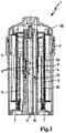
- a fluid filter for an internal combustion engine is shown, in particular a fuel filter.
- the liquid to be filtered enters the liquid filter 1 from below through an inlet channel 10 and flows upwards in the direction of the arrow 16 through the inlet channel 10, which is arranged in a channel component in the center of the liquid filter.
- the liquid filter 1 further comprises in the cylindrical housing 2 on an annular filter element 3, which is flowed through by the liquid radially from outside to inside of the medium to be cleaned.
- the material of the filter element 3 is supported and held by a arranged on the radially inner support frame 4, which preferably consists of plastic.
- the radial inner side of the filter element 3 forms the clean side, the radial outer side of the raw side.
- a coalescing medium 30 is arranged between the filter element 3 and the support frame 4, which coalesces the water droplets contained in the fuel into larger drops.
- recesses are introduced, via which the filter element 3 passing flow can enter into the interior of the support frame 4.
- a deflection member 50 is arranged in the form of an annular block wall within the support frame 4.
- the deflecting part 50 extends at least as far as the upper edge of the discharge opening 6, but preferably beyond, in order to ensure the flow of the fluid pointing downwards in the direction of the bottom.
- the upper end edge of the deflecting 50 is located in the upper Half of the filter element, based on the total axial height of the filter element.
- the upper end edge of the deflecting part 50 in this case forms an overflow region 5, via which the flow emerging from the filter element is guided downwards in the direction of the outflow opening 6.
- a separation screen 9 is arranged for improved water separation in front of the discharge opening 6, which is preferably made hydrophobic and prevents the water droplets from entering the discharge opening. This is facilitated in particular by the fact that the water droplets do not meet perpendicular to the separating screen 9 but due to the flow deflection at an acute angle, whereby the water droplets are not pressed by a frontal flow through the separating screen 9.
- the discharge opening 6 is at a radial distance to the clean side of the filter element 3 and to the inside of the support frame 4 and the deflecting 50. Between outflow 6 and deflecting 50, the separated water can fall down to the discharge opening 7. This space is through a drain hole connected to the tank return and vent channel 12 in the center of the liquid filter.
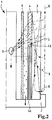
- a filter device 1 with a filter element 3 in a filter housing 2 is shown.
- the filter element 3 is annular,.
- the lower part 4a is executed closed and forms a deflection in the form of a blockade wall.
- the medium flowing through the filter element 3 radially from the outside to the inside can, as shown by the flow arrows 8, flow axially along the wall side of the deflection part 4a facing the filter element 3 up to the overflow area 5 which is located at the upper end edge of the deflection part. Only axially above the upper end edge is an outlet of the flow on the clean side of the filter element possible.
- the front edge with the overflow region 5 is axially at least at the same height, but preferably slightly higher than the discharge opening 6, which is located downstream of the filter element.
- a separation screen 9 which is arranged downstream of the support frame 4 including the deflection 4a and the discharge opening 6, wherein the separating screen 9 is arranged both to the deflection and the outflow each at a distance.
- the separation screen 9 is made hydrophobic, whereby the separation efficiency is improved and the entrained in the flow 8 water particles at the Be separated downstream of the separating screen 9, whereupon the separated water droplets can flow down into the plenum and are discharged from there via the discharge from the filter device.
Landscapes
- Chemical & Material Sciences (AREA)
- Chemical Kinetics & Catalysis (AREA)
- Engineering & Computer Science (AREA)
- Combustion & Propulsion (AREA)
- Physics & Mathematics (AREA)
- Thermal Sciences (AREA)
- Mechanical Engineering (AREA)
- General Engineering & Computer Science (AREA)
- Filtration Of Liquid (AREA)
- Lubrication Details And Ventilation Of Internal Combustion Engines (AREA)
Description
- Die Erfindung bezieht sich auf eine Filtereinrichtung, insbesondere einen Flüssigkeitsfilter, nach dem Oberbegriff des Anspruches 1.
- Aus der
DE 101 23 190 A1 ist ein Kraftstofffilter mit Wasser abscheidenden Mitteln bekannt. Der Filter ist zweistufig mit zwei ineinander gesetzten, zylindrischen Filterelementen ausgeführt, welche radial von dem Kraftstoff durchströmt werden, wobei das stromauf gelegene Filterelement aus hydrophilem Material und das stromab liegende Filterelement aus hydrophobem Material besteht. Nach dem Durchströmen des ersten, hydrophilen Filters gelangt der gereinigte Kraftstoff einschließlich der Wasseranteile an die äußere Mantelfläche des zweiten, hydrophoben Filters, an welchem das Wasser abgeschieden und axial nach unten abgeleitet wird. - Aus der
WO 2008/077954 A2 ist ein Kraftstofffilter bekannt, der ein ringförmiges, radial von außen nach innen zu durchströmendes Filterelement sowie ein ebenfalls ringförmiges, im Filterelement aufgenommenes Siebgewebeelement umfasst. Der Kraftstoff wird zunächst zur Partikelfilterung radial durch das Filterelement geleitet und muss vor der Anströmung des Siebgewebeelements zunächst an der Unterkante eines Gehäuseeinsatzes vorbeiströmen, welcher zur Umlenkung des Kraftstoffes dient. Im Bereich der unteren Stirnkante des Gehäuseeinsatzes erfolgt eine erste Wasserabscheidung, gefolgt von einer weiteren Wasserabscheidung an dem Siebgewebeelement. - Kraftstofffilter sind aus
EP 0405447 A2 ,US 2008/135469 A1 ,US 6554139 B1 ,US 2008/0245719 A undDE 102008038160 A1 bekannt. - Der Erfindung liegt die Aufgabe zu Grunde, eine Filtereinrichtung mit verbessertem Wirkungsgrad zur Abscheidung von Partikeln bzw. mitgeführtem Medium anzugeben.
- Diese Aufgabe wird erfindungsgemäß mit den Merkmalen des Anspruches 1 gelöst. Die Unteransprüche geben zweckmäßige Weiterbildungen an.
- Die erfindungsgemäße Filtereinrichtung bezieht sich vorzugsweise auf Flüssigkeitsfilter, insbesondere Kraftstofffilter wie Filtereinrichtungen für Dieselkraftstoff oder Ottokraftstoff oder ggf. auch Ölfilter in Brennkraftmaschinen. Bei derartigen Flüssigkeitsfiltern wird beispielsweise Wasser, das im Kraftstoff bzw. Öl enthalten ist, ausgefiltert und aus der Filtereinrichtung abgeleitet. Grundsätzlich kommt aber auch eine Anwendung auf Filtereinrichtungen zur Filtration gasförmiger Fluide in Betracht, beispielsweise Luftfilter für Brennkraftmaschinen, aus denen ebenfalls vorzugsweise eine mitgeführte Flüssigkeit, in der Regel Wasser, mittels der Filtereinrichtung abgeschieden wird.
- Die erfindungsgemäße Filtereinrichtung weist in einem zylindrischen Gehäuse ein ringförmiges Filterelement auf, mit einem an der radialen Innenseite angeordneten Stützgerüst, wobei das Filterelement von einem zu reinigenden Fluid radial von außen nach innen durchströmt wird, und wobei zwischen dem Filterelement und dem Stützgerüst ein Coaleszenzmedium angeordnet ist, wobei stromab des Filterelements eine Abströmöffnung zur Ableitung des gereinigten Mediums angeordnet ist, welche sich in dem vom Filterelement umschlossenen Innenraum befindet. Zwischen dem Filterelement und der Abströmöffnung, innerhalb des Stützgerüsts, befindet sich ein vorzugsweise strömungsdichtes Umlenkteil, welches separat von dem Stützgerüst ausgebildet ist und an dem ein Überströmbereich für die Strömung des gereinigten Mediums von dem Filterelement zur Abströmöffnung gebildet ist, wobei zwischen dem Umlenkteil und der Abströmöffnung ein Abscheidebauteil für abzuscheidende Partikel bzw. Tröpfchen, die nach dem Durchströmen des Filterelementes noch in der Fluidströmung enthalten sind, angeordnet ist. Das Umlenkteil ist als ringförmige Blockadewand ausgeführt, wobei die in Strömungsrichtung in Richtung einer Austragsöffnung für die Ableitung gesammelten Wassers betrachtet, obere Stirnkante der Blockadewand bei Anströmung bzw. Durchströmung des Filterelements über seine axiale Höhe einen Überströmbereich (5) für die Strömung des Mediums von dem Filterelement (3) zur Abströmöffnung (6) bildet, wobei sich die obere Stirnkante des Umlenkteils in der oberen Hälfte des Filterelements befindet, bezogen auf die gesamte axiale Höhe des Filterelements. Die Oberkante der Abströmöffnung liegt, bezogen auf das Umlenkteil, auf gleicher Höhe oder unterhalb des Überströmbereichs am Umlenkteil. Die Strömungsrichtung des gereinigten Fluids zwischen der Reinseite des Filterelements und der Abströmöffnung ist, bezogen auf die reguläre Einbaulage, in der das Filterelement über seine axiale Höhe stromab Richtung Austragsöffnung angeströmt bzw. durchströmt wird, in Richtung des Gewichtskraftvektors gerichtet.
- Mit dieser Ausführung ist gewährleistet, dass die Strömung des vorgereinigten Mediums zwischen der Reinseite des Filterelements und der Abströmöffnung bezogen auf die reguläre Einbaulage, in der das Filterelement über seine axiale Höhe angeströmt bzw. durchströmt wird, mit einer nach unten gerichteten Komponente erfolgt, also mit einer Komponente in Richtung des Gewichtskraftvektors. Dies hat den Vorteil, dass die Strömung nicht mehr der Gewichtskraft der abzuscheidenden Tröpfchen entgegengerichtet, sondern gleichgerichtet ist, wodurch der Abscheidegrad erhöht wird. Soll beispielsweise mitgeführtes Wasser aus dem Kraftstoff oder Öl abgeschieden werden, so entstehen auf Grund der erfindungsgemäßen Relativposition von Überströmbereich am Umlenkteil und Abströmöffnung zueinander stromab des Überströmbereichs nach unten gerichtete Strömungskomponenten, welche zu der Abströmöffnung führen, so dass die Sedimentationsrichtung der Wassertropfen und die Hauptströmungsrichtung jeweils zumindest in Schwerkraftrichtung ausgerichtet sind. Die Wassertropfen lagern sich noch vor dem Austritt über die Abströmöffnung in einem Abscheideraum in Gehäuse der Filtereinrichtung ab und können aus diesem ausgetragen werden.
- Bei Ausführungen aus dem Stand der Technik, bei denen die die Wasserpartikel enthaltende Strömung nach oben in Richtung der Abströmöffnung geführt ist, ist dagegen eine Abtrennung der Wassertropfen nicht möglich, wenn die Sedimentationsgeschwindigkeit kleiner als die Strömungsgeschwindigkeit ist; in diesem Fall werden die Wassertropfen in der aufwärtsgerichteten Strömung mittransportiert. Bei der erfindungsgemäßen Ausführung spielt dagegen das Verhältnis der Sedimentationsgeschwindigkeit zur Strömungsgeschwindigkeit für die Abscheidung keine entscheidende Rolle, wodurch der Abscheidegrad erheblich verbessert ist.
- Erreicht für die nach unten gerichtete Strömung durch das Umlenkteil bzw. den Überströmbereich am Umlenkteil, was den Vorteil aufweist, dass am Filterelement selbst keine Modifikationen erforderlich sind. Es können somit Filterelemente ohne Änderungen oder Anpassungen verwendet werden.
- Der Überströmbereich am Umlenkteil ist entweder in Form einer Ausnehmung in dem Umlenkteil, oder, gemäß bevorzugter Ausführung, unmittelbar an der Stirnseite bzw. Stirnkante des Umlenkteils ausgebildet. Erfindungsgemäß ist das Umlenkteil als eine ringförmige Blockadewand ausgeführt, deren obere Stirnkante den Überströmbereich bildet bzw. diesen begrenzt. Die Blockadewand liegt im Strömungsbereich zwischen der Reinseite des Filterelements und der Abströmöffnung und zwingt die Strömung, welche das Filterelement passiert hat, zu einer Umlenkung, um die gewünschte Strömung vom Umlenkteil mit der nach unten gerichteten Komponente hin zur Abströmöffnung zu erreichen. Dies hat außerdem den weiteren Vorteil, dass das Filterelement über seine gesamte axiale Höhe von dem zu reinigenden Fluid angeströmt werden kann, da erst im Bereich der Reinseite die Strömungsumlenkung an dem Umlenkteil erfolgt.
- Das Umlenkteil ist erfindungsgemäß auf Abstand zur Reinseite angeordnet, wobei diese Ausführung den Vorteil aufweist, dass die radiale Durchströmung durch das Filterelement ohne Beeinträchtigung bleibt, so dass über die gesamte axiale Höhe und über die gesamte radiale Dicke des Filterelementes ein gleich bleibender, sich in Radialrichtung von außen nach innen erstreckender Strömungsvektor gegeben ist. Erst nach dem Austritt über die Reinseite des Filterelementes erfolgt die Umlenkung entlang der Wandseite des Umlenkteils, welche der Reinseite des Filterelementes zugewandt ist. Mit dem Erreichen des Überströmbereichs an der Stirnkante des Umlenkteils wird auf Grund der Druckverhältnisse eine Strömungsrichtung mit einer Komponente in Richtung des Gewichtskraftvektors eingestellt.
- Die erfindungsgemäße Filtereinrichtung bezieht sich auf ringförmige Filterelemente, welche radial von außen nach innen durchströmt werden. Grundsätzlich möglich ist aber auch eine nicht erfindungsgemäße Ausführung eines Filterelementes beispielsweise als ebene Filterplatte. In der erfindungsgemäßen ringförmigen Ausführung des Filterelementes ist auch das Umlenkteil ringförmig ausgebildet, wohingegen bei einem nicht erfindungsgemäßen ebenen bzw. plattenförmigen Filterelement auch das Umlenkteil als ebene Blockadewand ausgeführt ist, welche entweder unmittelbar an der Reinseite des Filterelementes oder auf Abstand zu dieser liegt.
- Das Filterelement ist an dem Stützgerüst, gehalten, welches sich insbesondere an der Reinseite des Filterelementes befindet. In der erfindungsgemäßen ringförmigen Ausführung des Filterelementes bildet das Stützgerüst einen Zylinder an der Innenseite des Filterelementes.
- Das Umlenkteil ist separat von dem Stützgerüst ausgeführt. In der separaten Ausführung ist das Umlenkteil zweckmäßigerweise auf Abstand zur Reinseite des Filterelementes angeordnet.
- Erfindungsgemäß ist vorgesehen, dass zwischen dem Umlenkteil und der Abströmöffnung ein Abscheidebauteil für die abzuscheidenden Partikel bzw. Tröpfchen ausgebildet ist. Das Abscheidebauteil dient zur Abscheidung der Partikel bzw. Tröpfchen, die nach dem Durchströmen des Filterelementes noch in der Fluidströmung enthalten sind. Das Abscheidebauteil ist beispielsweise als Sieb ausgeführt, insbesondere aus einem hydrophobem Material oder mit einer hydrophoben Beschichtung, so dass das zu reinigende Medium durch die Öffnungen im Sieb hindurchtreten kann und die abzuscheidenden Partikel bzw. Tröpfchen an der Siebwandung hängenbleiben und in den Sammelraum abströmen. Stromab des Siebs befindet sich die Abströmöffnung, über die das gereinigte und von den abzuscheidenden Partikeln bzw. Tröpfchen befreite Fluid abströmt.
- Erfindungsgemäß ist zwischen dem Filterelement und dem Stützgerüst ein Coaleszenzmedium angeordnet, welches die im Kraftstoff enthaltenen Wassertröpfchen zu größeren Tropfen zusammenführt.
- Der Sammelraum für die abzuscheidenden Partikel bzw. Tröpfchen befindet sich unterhalb der Abströmöffnung und ist mit einer Austragsöffnung zum Ableiten der abgeschiedenen Partikel bzw. Tröpfchen versehen.
- Weitere Vorteile und zweckmäßige Ausführungen sind den weiteren Ansprüchen, der Figurenbeschreibung und den Zeichnungen zu entnehmen. Es zeigen:
-
Fig. 1 eine Ansicht eines Flüssigkeitsfilters im Schnitt, -
Fig. 2 eine schematische Darstellung eines nicht erfindungsgemäßen Flüssigkeitsfilters, ebenfalls im Schnitt. - In den Figuren sind gleiche Bauteile mit gleichen Bezugszeichen versehen.
- In
Fig. 1 ist ein Flüssigkeitsfilter für eine Brennkraftmaschine dargestellt, insbesondere ein Kraftstofffilter. Die zu filternde Flüssigkeit tritt durch einen Einlasskanal 10 von unten in den Flüssigkeitsfilter 1 ein und strömt in Pfeilrichtung 16 durch den Einlasskanal 10, der in einem Kanalbauteil im Zentrum des Flüssigkeitsfilters angeordnet ist nach oben. - Der Flüssigkeitsfilter 1 weist weiter in dem zylindrischen Gehäuse 2 ein ringförmiges Filterelement 3 auf, das von der Flüssigkeit radial von außen nach innen von dem zu reinigenden Medium durchströmt wird. Das Material des Filterelementes 3 ist von einem an der radialen Innenseite angeordneten Stützgerüst 4 getragen und gehalten, welches vorzugsweise aus Kunststoff besteht. Die radiale Innenseite des Filterelementes 3 bildet die Reinseite, die radiale Außenseite die Rohseite. Erfindungsgemäß ist zwischen dem Filterelement 3 und dem Stützgerüst 4 ein Coaleszenzmedium 30 angeordnet, welches die im Kraftstoff enthaltenen Wassertröpfchen zu größeren Tropfen zusammenführt. In das Stützgerüst 4 sind Ausnehmungen eingebracht, über die die das Filterelement 3 passierende Strömung in den Innenraum des Stützgerüsts 4 eintreten kann.
- In dem von dem ringförmigen Filterelement 3 umschlossenen Innenraum befindet sich eine Abströmöffnung 6, über die das über die Reinseite des Filterelementes ausgetretene Fluid aus dem Flüssigkeitsfilter 1 in den Auslasskanal 11 abgeleitet wird. Um eine Strömungsrichtung des gereinigten Fluids von oben nach unten in Richtung des Gewichtskraftvektors sicherzustellen, ist innerhalb des Stützgerüsts 4 ein Umlenkteil 50 in Form einer ringförmigen Blockadewand angeordnet. Das Umlenkteil 50 erstreckt sich für diesen Fall mindestens bis zur Oberkante der Abströmöffnung 6, vorzugsweise jedoch darüber hinaus, um die nach unten in Richtung des Bodens weisende Strömung des Fluids zu gewährleisten. Die obere Stirnkante des Umlenkteils 50 befindet sich in der oberen Hälfte des Filterelementes, bezogen auf die gesamte axiale Höhe des Filterelementes. Die obere Stirnkante des Umlenkteils 50 bildet hierbei einen Überströmbereich 5, über den die aus dem Filterelement austretende Strömung nach unten in Richtung der Abströmöffnung 6 geführt wird.
- Die mitgeführten Wassertröpfchen im Kraftstoff, welche das Filterelement 3 passiert haben, werden noch vor der Ausleitung über die Abströmöffnung 6 innerhalb des Umlenkteils 50 abgeschieden und können in den unteren Bereich der Filtereinrichtung abströmen, in welchem ein Sammelbereich mit einer Austragöffnung 7 für die Ableitung des gesammelten Wassers gebildet ist. Vorzugsweise ist für eine verbesserte Wasserabscheidung vor der Abströmöffnung 6 ein Abscheidesieb 9 angeordnet, welches bevorzugt hydrophob ausgeführt ist und die Wassertröpfchen am Eintreten in die Abströmöffnung hindert. Dies wird insbesondere dadurch erleichtert, dass die Wassertröpfchen nicht senkrecht auf das Abscheidesieb 9 treffen sondern aufgrund der Strömungsumlenkung in einem spitzen Winkel, wodurch die Wassertröpfchen nicht durch eine frontale Anströmung durch das Abscheidesieb 9 gepresst werden.
- Die Abströmöffnung 6 liegt auf radialem Abstand zur Reinseite des Filterelementes 3 bzw. zur Innenseite des Stützgerüstes 4 und des Umlenkteils 50. Zwischen Abströmöffnung 6 und Umlenkteil 50 kann das abgeschiedene Wasser nach unten zur Austragsöffnung 7 absinken. Dieser Zwischenraum ist durch eine Ablaufbohrung mit dem Tankrücklauf- und Entlüftungskanal 12 im Zentrum des Flüssigkeitsfilters verbunden.
- Auch in
Fig. 2 ist eine Filtereinrichtung 1 mit einem Filterelement 3 in einem Filtergehäuse 2 dargestellt. Das Filterelement 3 ist ringförmig ausgebildet,. An der Strömungsinnenseite ist das Filterelement 3 von einem Stützgerüst 4 gehalten, dessen unterer Teil 4a geschlossen ausgeführt ist und ein Umlenkteil in Form einer Blockadewand bildet. Das das Filterelement 3 radial von außen nach innen durchströmende Medium kann, wie mit den Strömungspfeilen 8 dargestellt, an der dem Filterelement 3 zugewandten Wandseite des Umlenkteils 4a axial bis zum Überströmbereich 5 entlang strömen, der sich an der oberen Stirnkante des Umlenkteils befindet. Erst axial oberhalb der oberen Stirnkante ist ein Austritt der Strömung über die Reinseite des Filterelementes möglich. Die Stirnkante mit dem Überströmbereich 5 liegt axial mindestens auf gleicher Höhe, vorzugsweise aber geringfügig höher als die Abströmöffnung 6, welche sich stromab des Filterelementes befindet. - Zur Verbesserung der Abscheidung der mitgeführten Wasserpartikel dient ein Abscheidesieb 9, das stromab des Stützgerüsts 4 einschließlich des Umlenkteils 4a und der Abströmöffnung 6 angeordnet ist, wobei das Abscheidesieb 9 sowohl zum Umlenkteil als auch zur Abströmöffnung jeweils auf Abstand angeordnet ist. Das Abscheidesieb 9 ist hydrophob ausgeführt, wodurch die Abscheidewirkung verbessert wird und die in der Strömung 8 mitgeführten Wasserpartikel an der Abströmseite des Abscheidesiebs 9 abgeschieden werden, woraufhin die abgeschiedenen Wassertröpfchen nach unten in den Sammelraum abströmen können und von dort aus über die Austragöffnungen aus der Filtereinrichtung abgeleitet werden.
Claims (3)
- Filtereinrichtung, insbesondere Flüssigkeitsfilter, mit einem in einem zylindrischen Gehäuse (2) aufgenommenen ringförmigen Filterelement (3) mit einem an der radialen Innenseite angeordneten Stützgerüst (4), wobei das Filterelement (3) an dem Stützgerüst (4) gehalten ist, wobei das Filterelement (3) von einem zu reinigenden Fluid radial von außen nach innen durchströmt wird und wobei zwischen dem Filterelement (3) und dem Stützgerüst (4) ein Coaleszenzmedium (30) angeordnet ist, und mit einer stromab des Filterelements (3) in dem vom Filterelement (3) umschlossenen Innenraum angeordneten Abströmöffnung (6) zur Ableitung des gereinigten Mediums, wobei zwischen dem Filterelement (3) und der Abströmöffnung (6) innerhalb des Stützgerüsts (4) ein Umlenkteil (50) angeordnet ist, welches separat von dem Stützgerüst (4) ausgebildet ist und wobei zwischen dem Umlenkteil (50) und der Abströmöffnung (6) ein Abscheidebauteil (9) für abzuscheidende Partikel bzw. Tröpfchen, die nach dem Durchströmen des Filterelementes (3) noch in der Fluidströmung enthalten sind, angeordnet ist, dadurch gekennzeichnet, dass am Umlenkteil (50), welches als ringförmige Blockadewand ausgeführt ist, wobei die in Strömungsrichtung in Richtung einer Austragsöffnung (7) für die Ableitung gesammelten Wassers betrachtet, obere Stirnkante der Blockadewand bei Anströmung bzw. Durchströmung des Filterelements (3) über seine axiale Höhe einen Überströmbereich (5) für die Strömung des Mediums von dem Filterelement (3) zur Abströmöffnung (6) bildet, wobei sich die obere Stirnkante des Umlenkteils (50) in der oberen Hälfte des Filterelements (3) befindet, bezogen auf die gesamte axiale Höhe des Filterelements (3), wobei die Oberkante der Abströmöffnung (6), bezogen auf das Umlenkteil (50), auf gleicher Höhe oder unterhalb des Überströmbereichs (5) am Umlenkteil (50) liegt, die Strömungsrichtung des gereinigten Fluids zwischen der Reinseite des Filterelements (3) und der Abströmöffnung (6), bezogen auf die reguläre Einbaulage, in der das Filterelement über seine axiale Höhe stromab Richtung Austragsöffnung (7) angeströmt bzw. durchströmt wird, in Richtung des Gewichtskraftvektors gerichtet ist.
- Filtereinrichtung nach Anspruch 1, dadurch gekennzeichnet, dass das Abscheidebauteil (9) als ein Sieb ausgebildet ist.
- Filtereinrichtung nach einem der Ansprüche 1 oder 2, dadurch gekennzeichnet, dass unterhalb der Abströmöffnung (6) eine Austragsöffnung (7) zum Ableiten abgeschiedener Tröpfchen angeordnet ist.
Applications Claiming Priority (2)
| Application Number | Priority Date | Filing Date | Title |
|---|---|---|---|
| DE102010023650A DE102010023650A1 (de) | 2010-06-14 | 2010-06-14 | Filtereinrichtung, insbesondere Flüssigkeitsfilter |
| PCT/EP2011/058785 WO2011157535A1 (de) | 2010-06-14 | 2011-05-30 | Filtereinrichtung, insbesondere flüssigkeitsfilter |
Publications (2)
| Publication Number | Publication Date |
|---|---|
| EP2579958A1 EP2579958A1 (de) | 2013-04-17 |
| EP2579958B1 true EP2579958B1 (de) | 2019-03-06 |
Family
ID=44626905
Family Applications (1)
| Application Number | Title | Priority Date | Filing Date |
|---|---|---|---|
| EP11724599.3A Active EP2579958B1 (de) | 2010-06-14 | 2011-05-30 | Filtereinrichtung, insbesondere flüssigkeitsfilter |
Country Status (5)
| Country | Link |
|---|---|
| US (1) | US9486724B2 (de) |
| EP (1) | EP2579958B1 (de) |
| CN (1) | CN102933276B (de) |
| DE (1) | DE102010023650A1 (de) |
| WO (1) | WO2011157535A1 (de) |
Families Citing this family (9)
| Publication number | Priority date | Publication date | Assignee | Title |
|---|---|---|---|---|
| DE102008038160A1 (de) | 2008-08-18 | 2010-02-25 | Mahle International Gmbh | Filtereinrichtung |
| DE102012013743A1 (de) * | 2012-07-12 | 2014-01-16 | Mann + Hummel Gmbh | Wasserabscheidevorrichtung, Filterelement eines Kraftstoff-Filters und Kraftstofffilter |
| DE102012018662A1 (de) * | 2012-09-21 | 2014-04-17 | Mann+Hummel Gmbh | Hohlzylindrisches Filterelement für einen Flüssigkeitsfilter |
| DE102012024349B4 (de) * | 2012-12-13 | 2015-11-05 | Mann + Hummel Gmbh | Filter zur Filtrierung von Flüssigkeiten und Filterelement eines derartigen Filters |
| DE102013015143B4 (de) * | 2013-09-13 | 2016-05-25 | Mann + Hummel Gmbh | Filter für Fluid, Filterelement und Filtergehäuse eines Filters |
| DE102013016976A1 (de) * | 2013-10-14 | 2015-04-16 | Mann + Hummel Gmbh | Filterelement und Filtersystem für ein Flüssigmedium, insbesondere Dieselkraftstoff |
| WO2015112694A1 (en) * | 2014-01-24 | 2015-07-30 | Cummins Filtration Ip, Inc. | Filter including spring tube bypass assembly |
| DE102014009327A1 (de) * | 2014-06-27 | 2015-12-31 | Mann+Hummel Gmbh | Filtereinrichtung, insbesondere Flüssigkeitsfilter |
| DE102015013351A1 (de) * | 2015-10-15 | 2017-04-20 | Mann + Hummel Gmbh | Koaleszenzelement und Filterelement mit einem Koaleszenzelement |
Citations (2)
| Publication number | Priority date | Publication date | Assignee | Title |
|---|---|---|---|---|
| US20080245719A1 (en) * | 2005-02-22 | 2008-10-09 | Baldwin Filters, Inc. | Filter Element And Filter Assembly Including Locking Mechanism |
| DE102008038160A1 (de) * | 2008-08-18 | 2010-02-25 | Mahle International Gmbh | Filtereinrichtung |
Family Cites Families (12)
| Publication number | Priority date | Publication date | Assignee | Title |
|---|---|---|---|---|
| CA963400A (en) * | 1971-09-29 | 1975-02-25 | Vladimir Rizek | Combination filter and water separator |
| US4384962A (en) * | 1981-03-06 | 1983-05-24 | Stant Inc. | Fuel-water separator |
| US5017285A (en) * | 1989-06-28 | 1991-05-21 | Stanadyne Automotive Corp. | Fuel filter and cartridge assembly |
| DE19538883A1 (de) * | 1995-10-19 | 1997-04-24 | Bosch Gmbh Robert | Filter für Flüssigkeiten, insbesondere Dieselkraftstoff |
| IT1316849B1 (it) * | 2000-03-24 | 2003-05-12 | Sogefi Filtration Spa | Filtro per carburante per motori diesel |
| US6554139B1 (en) * | 2000-06-01 | 2003-04-29 | Parker-Hannifin Corporation | Extension and locking assembly for dripless element, and container therefore |
| DE10123190A1 (de) | 2001-05-12 | 2002-11-14 | Mahle Filtersysteme Gmbh | Kraftstofffilter mit wasserabscheidenden Mitteln |
| US6902669B2 (en) * | 2002-09-13 | 2005-06-07 | Fleetguard, Inc. | Filter cartridge with floating seal |
| DE102006034077A1 (de) * | 2005-08-16 | 2007-02-22 | Robert Bosch Gmbh | Filtereinrichtung mit einer Heizung |
| FR2909732B1 (fr) * | 2006-12-12 | 2011-09-23 | Filtrauto | Dispositif de filtration de carburant a deux niveaux |
| DE202006019301U1 (de) | 2006-12-23 | 2008-04-30 | Mann+Hummel Gmbh | Kraftstofffilter |
| WO2011005990A1 (en) * | 2009-07-08 | 2011-01-13 | Cummins Filtration Ip, Inc. | Dual stage filtration with barrier for fuel water separation |
-
2010
- 2010-06-14 DE DE102010023650A patent/DE102010023650A1/de not_active Withdrawn
-
2011
- 2011-05-30 CN CN201180029517.8A patent/CN102933276B/zh not_active Expired - Fee Related
- 2011-05-30 WO PCT/EP2011/058785 patent/WO2011157535A1/de active Application Filing
- 2011-05-30 EP EP11724599.3A patent/EP2579958B1/de active Active
-
2012
- 2012-12-13 US US13/713,869 patent/US9486724B2/en not_active Expired - Fee Related
Patent Citations (2)
| Publication number | Priority date | Publication date | Assignee | Title |
|---|---|---|---|---|
| US20080245719A1 (en) * | 2005-02-22 | 2008-10-09 | Baldwin Filters, Inc. | Filter Element And Filter Assembly Including Locking Mechanism |
| DE102008038160A1 (de) * | 2008-08-18 | 2010-02-25 | Mahle International Gmbh | Filtereinrichtung |
Also Published As
| Publication number | Publication date |
|---|---|
| EP2579958A1 (de) | 2013-04-17 |
| US20130098824A1 (en) | 2013-04-25 |
| CN102933276B (zh) | 2015-07-08 |
| WO2011157535A1 (de) | 2011-12-22 |
| DE102010023650A1 (de) | 2011-12-15 |
| US9486724B2 (en) | 2016-11-08 |
| CN102933276A (zh) | 2013-02-13 |
Similar Documents
| Publication | Publication Date | Title |
|---|---|---|
| EP2579958B1 (de) | Filtereinrichtung, insbesondere flüssigkeitsfilter | |
| EP2602473B1 (de) | Kraftstofffilter einer Brennkraftmaschine und Filterelement eines Kraftstofffilters | |
| EP2145099B1 (de) | Kraftstoffzuführeinrichtung, insbesondere für eine brennkraftmaschine | |
| DE102009025393B4 (de) | 3-stufiger Kraftstofffilter | |
| EP2663378B1 (de) | Filtervorrichtung | |
| DE102008038160A1 (de) | Filtereinrichtung | |
| DE102011122632A1 (de) | Fliehkraftabscheider und Filteranordnung | |
| DE102013012918B4 (de) | Flüssigkeitsfilter und Filterelement, insbesondere für Kraftstoff | |
| DE102005059014A1 (de) | Ölabscheider für einen Verbrennungsmotor, insbesondere Dieselmotor | |
| EP2049222B1 (de) | Filtervorrichtung | |
| WO2009095339A1 (de) | Flüssigkeitsfilter, insbesondere für kraftstoff | |
| EP0416146B1 (de) | Vorrichtung zum Abtrennen von Feststoffteilchen und Fluiden höherer Dichte von Fluiden niederer Dichte | |
| EP2886181B1 (de) | Flüssigkeitsfilter | |
| DE102013012917B4 (de) | Flüssigkeitsfilter, insbesondere für Kraftstoff | |
| EP3348804B1 (de) | Schmiermittelbehälter für ein hydrauliksystem | |
| DE102010030987B4 (de) | Fluidfilter | |
| EP2463004A1 (de) | Gasabscheider | |
| DE10006353A1 (de) | Filtereinrichtung für Kraftstoffe | |
| WO2012031864A1 (de) | Kraftstofffilter zur filterung von kraftstoff | |
| DE102004041768B4 (de) | Fliehkraftabscheider | |
| DE102016009487B4 (de) | Abscheideelement, Vorrichtung sowie Verfahren zur Abscheidung von Flüssigkeit aus Rohgas oder aus Rohgasgemisch einer Kraftmaschine oder eines Kompressors | |
| DE202008002927U1 (de) | Flüssigkeitsfilter, insbesondere für Kraftstoff | |
| DE102010062595B4 (de) | Filtereinrichtung | |
| EP3661621B1 (de) | Filterelement | |
| EP2556873B1 (de) | Kondensatabscheider |
Legal Events
| Date | Code | Title | Description |
|---|---|---|---|
| PUAI | Public reference made under article 153(3) epc to a published international application that has entered the european phase |
Free format text: ORIGINAL CODE: 0009012 |
|
| 17P | Request for examination filed |
Effective date: 20121105 |
|
| AK | Designated contracting states |
Kind code of ref document: A1 Designated state(s): AL AT BE BG CH CY CZ DE DK EE ES FI FR GB GR HR HU IE IS IT LI LT LU LV MC MK MT NL NO PL PT RO RS SE SI SK SM TR |
|
| DAX | Request for extension of the european patent (deleted) | ||
| 17Q | First examination report despatched |
Effective date: 20151222 |
|
| REG | Reference to a national code |
Ref country code: DE Ref legal event code: R079 Ref document number: 502011015452 Country of ref document: DE Free format text: PREVIOUS MAIN CLASS: B01D0029580000 Ipc: B01D0017040000 |
|
| GRAP | Despatch of communication of intention to grant a patent |
Free format text: ORIGINAL CODE: EPIDOSNIGR1 |
|
| STAA | Information on the status of an ep patent application or granted ep patent |
Free format text: STATUS: GRANT OF PATENT IS INTENDED |
|
| INTG | Intention to grant announced |
Effective date: 20180720 |
|
| RIC1 | Information provided on ipc code assigned before grant |
Ipc: F02M 37/22 20060101ALI20180709BHEP Ipc: B01D 17/04 20060101AFI20180709BHEP Ipc: B01D 29/21 20060101ALI20180709BHEP Ipc: B01D 36/00 20060101ALI20180709BHEP Ipc: B01D 29/92 20060101ALI20180709BHEP Ipc: B01D 17/00 20060101ALI20180709BHEP |
|
| GRAJ | Information related to disapproval of communication of intention to grant by the applicant or resumption of examination proceedings by the epo deleted |
Free format text: ORIGINAL CODE: EPIDOSDIGR1 |
|
| STAA | Information on the status of an ep patent application or granted ep patent |
Free format text: STATUS: EXAMINATION IS IN PROGRESS |
|
| GRAP | Despatch of communication of intention to grant a patent |
Free format text: ORIGINAL CODE: EPIDOSNIGR1 |
|
| STAA | Information on the status of an ep patent application or granted ep patent |
Free format text: STATUS: GRANT OF PATENT IS INTENDED |
|
| INTC | Intention to grant announced (deleted) | ||
| INTG | Intention to grant announced |
Effective date: 20181205 |
|
| GRAS | Grant fee paid |
Free format text: ORIGINAL CODE: EPIDOSNIGR3 |
|
| GRAA | (expected) grant |
Free format text: ORIGINAL CODE: 0009210 |
|
| STAA | Information on the status of an ep patent application or granted ep patent |
Free format text: STATUS: THE PATENT HAS BEEN GRANTED |
|
| RAP1 | Party data changed (applicant data changed or rights of an application transferred) |
Owner name: MANN + HUMMEL GMBH |
|
| AK | Designated contracting states |
Kind code of ref document: B1 Designated state(s): AL AT BE BG CH CY CZ DE DK EE ES FI FR GB GR HR HU IE IS IT LI LT LU LV MC MK MT NL NO PL PT RO RS SE SI SK SM TR |
|
| REG | Reference to a national code |
Ref country code: GB Ref legal event code: FG4D Free format text: NOT ENGLISH |
|
| RIN1 | Information on inventor provided before grant (corrected) |
Inventor name: DUERR, ELKE Inventor name: SCHWEIKART, MARCO Inventor name: NISSLER, ELISABETH Inventor name: EPLI, SVEN Inventor name: TRAUTMANN, PIUS Inventor name: GLUECK, OLIVER Inventor name: JOKSCHAS, GUENTER Inventor name: SCHRECKENBERGER, DIETER Inventor name: EICHINGER, STEFAN Inventor name: VOLKMER, DANIEL |
|
| REG | Reference to a national code |
Ref country code: CH Ref legal event code: EP Ref country code: AT Ref legal event code: REF Ref document number: 1103780 Country of ref document: AT Kind code of ref document: T Effective date: 20190315 |
|
| RIN2 | Information on inventor provided after grant (corrected) |
Inventor name: SCHRECKENBERGER, DIETER Inventor name: JOKSCHAS, GUENTER Inventor name: VOLKMER, DANIEL Inventor name: EPLI, SVEN Inventor name: TRAUTMANN, PIUS Inventor name: SCHWEIKART, MARCO Inventor name: EICHINGER, STEFAN Inventor name: GLUECK, OLIVER Inventor name: NISSLER, ELISABETH Inventor name: DUERR, ELKE |
|
| REG | Reference to a national code |
Ref country code: DE Ref legal event code: R096 Ref document number: 502011015452 Country of ref document: DE |
|
| REG | Reference to a national code |
Ref country code: IE Ref legal event code: FG4D Free format text: LANGUAGE OF EP DOCUMENT: GERMAN |
|
| REG | Reference to a national code |
Ref country code: NL Ref legal event code: MP Effective date: 20190306 |
|
| REG | Reference to a national code |
Ref country code: LT Ref legal event code: MG4D |
|
| PG25 | Lapsed in a contracting state [announced via postgrant information from national office to epo] |
Ref country code: NO Free format text: LAPSE BECAUSE OF FAILURE TO SUBMIT A TRANSLATION OF THE DESCRIPTION OR TO PAY THE FEE WITHIN THE PRESCRIBED TIME-LIMIT Effective date: 20190606 Ref country code: FI Free format text: LAPSE BECAUSE OF FAILURE TO SUBMIT A TRANSLATION OF THE DESCRIPTION OR TO PAY THE FEE WITHIN THE PRESCRIBED TIME-LIMIT Effective date: 20190306 Ref country code: SE Free format text: LAPSE BECAUSE OF FAILURE TO SUBMIT A TRANSLATION OF THE DESCRIPTION OR TO PAY THE FEE WITHIN THE PRESCRIBED TIME-LIMIT Effective date: 20190306 Ref country code: LT Free format text: LAPSE BECAUSE OF FAILURE TO SUBMIT A TRANSLATION OF THE DESCRIPTION OR TO PAY THE FEE WITHIN THE PRESCRIBED TIME-LIMIT Effective date: 20190306 |
|
| PG25 | Lapsed in a contracting state [announced via postgrant information from national office to epo] |
Ref country code: NL Free format text: LAPSE BECAUSE OF FAILURE TO SUBMIT A TRANSLATION OF THE DESCRIPTION OR TO PAY THE FEE WITHIN THE PRESCRIBED TIME-LIMIT Effective date: 20190306 Ref country code: HR Free format text: LAPSE BECAUSE OF FAILURE TO SUBMIT A TRANSLATION OF THE DESCRIPTION OR TO PAY THE FEE WITHIN THE PRESCRIBED TIME-LIMIT Effective date: 20190306 Ref country code: RS Free format text: LAPSE BECAUSE OF FAILURE TO SUBMIT A TRANSLATION OF THE DESCRIPTION OR TO PAY THE FEE WITHIN THE PRESCRIBED TIME-LIMIT Effective date: 20190306 Ref country code: LV Free format text: LAPSE BECAUSE OF FAILURE TO SUBMIT A TRANSLATION OF THE DESCRIPTION OR TO PAY THE FEE WITHIN THE PRESCRIBED TIME-LIMIT Effective date: 20190306 Ref country code: GR Free format text: LAPSE BECAUSE OF FAILURE TO SUBMIT A TRANSLATION OF THE DESCRIPTION OR TO PAY THE FEE WITHIN THE PRESCRIBED TIME-LIMIT Effective date: 20190607 Ref country code: BG Free format text: LAPSE BECAUSE OF FAILURE TO SUBMIT A TRANSLATION OF THE DESCRIPTION OR TO PAY THE FEE WITHIN THE PRESCRIBED TIME-LIMIT Effective date: 20190606 |
|
| PG25 | Lapsed in a contracting state [announced via postgrant information from national office to epo] |
Ref country code: EE Free format text: LAPSE BECAUSE OF FAILURE TO SUBMIT A TRANSLATION OF THE DESCRIPTION OR TO PAY THE FEE WITHIN THE PRESCRIBED TIME-LIMIT Effective date: 20190306 Ref country code: ES Free format text: LAPSE BECAUSE OF FAILURE TO SUBMIT A TRANSLATION OF THE DESCRIPTION OR TO PAY THE FEE WITHIN THE PRESCRIBED TIME-LIMIT Effective date: 20190306 Ref country code: CZ Free format text: LAPSE BECAUSE OF FAILURE TO SUBMIT A TRANSLATION OF THE DESCRIPTION OR TO PAY THE FEE WITHIN THE PRESCRIBED TIME-LIMIT Effective date: 20190306 Ref country code: RO Free format text: LAPSE BECAUSE OF FAILURE TO SUBMIT A TRANSLATION OF THE DESCRIPTION OR TO PAY THE FEE WITHIN THE PRESCRIBED TIME-LIMIT Effective date: 20190306 Ref country code: SK Free format text: LAPSE BECAUSE OF FAILURE TO SUBMIT A TRANSLATION OF THE DESCRIPTION OR TO PAY THE FEE WITHIN THE PRESCRIBED TIME-LIMIT Effective date: 20190306 Ref country code: AL Free format text: LAPSE BECAUSE OF FAILURE TO SUBMIT A TRANSLATION OF THE DESCRIPTION OR TO PAY THE FEE WITHIN THE PRESCRIBED TIME-LIMIT Effective date: 20190306 Ref country code: PT Free format text: LAPSE BECAUSE OF FAILURE TO SUBMIT A TRANSLATION OF THE DESCRIPTION OR TO PAY THE FEE WITHIN THE PRESCRIBED TIME-LIMIT Effective date: 20190706 |
|
| PG25 | Lapsed in a contracting state [announced via postgrant information from national office to epo] |
Ref country code: PL Free format text: LAPSE BECAUSE OF FAILURE TO SUBMIT A TRANSLATION OF THE DESCRIPTION OR TO PAY THE FEE WITHIN THE PRESCRIBED TIME-LIMIT Effective date: 20190306 Ref country code: SM Free format text: LAPSE BECAUSE OF FAILURE TO SUBMIT A TRANSLATION OF THE DESCRIPTION OR TO PAY THE FEE WITHIN THE PRESCRIBED TIME-LIMIT Effective date: 20190306 |
|
| REG | Reference to a national code |
Ref country code: DE Ref legal event code: R097 Ref document number: 502011015452 Country of ref document: DE |
|
| REG | Reference to a national code |
Ref country code: CH Ref legal event code: PL |
|
| PG25 | Lapsed in a contracting state [announced via postgrant information from national office to epo] |
Ref country code: IS Free format text: LAPSE BECAUSE OF FAILURE TO SUBMIT A TRANSLATION OF THE DESCRIPTION OR TO PAY THE FEE WITHIN THE PRESCRIBED TIME-LIMIT Effective date: 20190706 |
|
| PLBE | No opposition filed within time limit |
Free format text: ORIGINAL CODE: 0009261 |
|
| STAA | Information on the status of an ep patent application or granted ep patent |
Free format text: STATUS: NO OPPOSITION FILED WITHIN TIME LIMIT |
|
| PG25 | Lapsed in a contracting state [announced via postgrant information from national office to epo] |
Ref country code: CH Free format text: LAPSE BECAUSE OF NON-PAYMENT OF DUE FEES Effective date: 20190531 Ref country code: MC Free format text: LAPSE BECAUSE OF FAILURE TO SUBMIT A TRANSLATION OF THE DESCRIPTION OR TO PAY THE FEE WITHIN THE PRESCRIBED TIME-LIMIT Effective date: 20190306 Ref country code: LI Free format text: LAPSE BECAUSE OF NON-PAYMENT OF DUE FEES Effective date: 20190531 Ref country code: DK Free format text: LAPSE BECAUSE OF FAILURE TO SUBMIT A TRANSLATION OF THE DESCRIPTION OR TO PAY THE FEE WITHIN THE PRESCRIBED TIME-LIMIT Effective date: 20190306 |
|
| REG | Reference to a national code |
Ref country code: BE Ref legal event code: MM Effective date: 20190531 |
|
| 26N | No opposition filed |
Effective date: 20191209 |
|
| GBPC | Gb: european patent ceased through non-payment of renewal fee |
Effective date: 20190606 |
|
| PG25 | Lapsed in a contracting state [announced via postgrant information from national office to epo] |
Ref country code: SI Free format text: LAPSE BECAUSE OF FAILURE TO SUBMIT A TRANSLATION OF THE DESCRIPTION OR TO PAY THE FEE WITHIN THE PRESCRIBED TIME-LIMIT Effective date: 20190306 Ref country code: LU Free format text: LAPSE BECAUSE OF NON-PAYMENT OF DUE FEES Effective date: 20190530 |
|
| PG25 | Lapsed in a contracting state [announced via postgrant information from national office to epo] |
Ref country code: TR Free format text: LAPSE BECAUSE OF FAILURE TO SUBMIT A TRANSLATION OF THE DESCRIPTION OR TO PAY THE FEE WITHIN THE PRESCRIBED TIME-LIMIT Effective date: 20190306 |
|
| PG25 | Lapsed in a contracting state [announced via postgrant information from national office to epo] |
Ref country code: IE Free format text: LAPSE BECAUSE OF NON-PAYMENT OF DUE FEES Effective date: 20190530 Ref country code: GB Free format text: LAPSE BECAUSE OF NON-PAYMENT OF DUE FEES Effective date: 20190606 |
|
| PG25 | Lapsed in a contracting state [announced via postgrant information from national office to epo] |
Ref country code: BE Free format text: LAPSE BECAUSE OF NON-PAYMENT OF DUE FEES Effective date: 20190531 |
|
| REG | Reference to a national code |
Ref country code: AT Ref legal event code: MM01 Ref document number: 1103780 Country of ref document: AT Kind code of ref document: T Effective date: 20190530 |
|
| PG25 | Lapsed in a contracting state [announced via postgrant information from national office to epo] |
Ref country code: AT Free format text: LAPSE BECAUSE OF NON-PAYMENT OF DUE FEES Effective date: 20190530 |
|
| PG25 | Lapsed in a contracting state [announced via postgrant information from national office to epo] |
Ref country code: CY Free format text: LAPSE BECAUSE OF FAILURE TO SUBMIT A TRANSLATION OF THE DESCRIPTION OR TO PAY THE FEE WITHIN THE PRESCRIBED TIME-LIMIT Effective date: 20190306 |
|
| PG25 | Lapsed in a contracting state [announced via postgrant information from national office to epo] |
Ref country code: MT Free format text: LAPSE BECAUSE OF FAILURE TO SUBMIT A TRANSLATION OF THE DESCRIPTION OR TO PAY THE FEE WITHIN THE PRESCRIBED TIME-LIMIT Effective date: 20190306 Ref country code: HU Free format text: LAPSE BECAUSE OF FAILURE TO SUBMIT A TRANSLATION OF THE DESCRIPTION OR TO PAY THE FEE WITHIN THE PRESCRIBED TIME-LIMIT; INVALID AB INITIO Effective date: 20110530 |
|
| PG25 | Lapsed in a contracting state [announced via postgrant information from national office to epo] |
Ref country code: MK Free format text: LAPSE BECAUSE OF FAILURE TO SUBMIT A TRANSLATION OF THE DESCRIPTION OR TO PAY THE FEE WITHIN THE PRESCRIBED TIME-LIMIT Effective date: 20190306 |
|
| PGFP | Annual fee paid to national office [announced via postgrant information from national office to epo] |
Ref country code: IT Payment date: 20230526 Year of fee payment: 13 |
|
| P01 | Opt-out of the competence of the unified patent court (upc) registered |
Effective date: 20230627 |
|
| PGFP | Annual fee paid to national office [announced via postgrant information from national office to epo] |
Ref country code: DE Payment date: 20240521 Year of fee payment: 14 |
|
| PGFP | Annual fee paid to national office [announced via postgrant information from national office to epo] |
Ref country code: FR Payment date: 20240528 Year of fee payment: 14 |