EP2579306A2 - Federklemmvorrichtung zur Befestigung eines Leistungshalbleiters - Google Patents
Federklemmvorrichtung zur Befestigung eines Leistungshalbleiters Download PDFInfo
- Publication number
- EP2579306A2 EP2579306A2 EP12183512.8A EP12183512A EP2579306A2 EP 2579306 A2 EP2579306 A2 EP 2579306A2 EP 12183512 A EP12183512 A EP 12183512A EP 2579306 A2 EP2579306 A2 EP 2579306A2
- Authority
- EP
- European Patent Office
- Prior art keywords
- power semiconductor
- housing
- clip
- fixing
- onto
- Prior art date
- Legal status (The legal status is an assumption and is not a legal conclusion. Google has not performed a legal analysis and makes no representation as to the accuracy of the status listed.)
- Withdrawn
Links
Images

Classifications
-
- H—ELECTRICITY
- H10—SEMICONDUCTOR DEVICES; ELECTRIC SOLID-STATE DEVICES NOT OTHERWISE PROVIDED FOR
- H10W—GENERIC PACKAGES, INTERCONNECTIONS, CONNECTORS OR OTHER CONSTRUCTIONAL DETAILS OF DEVICES COVERED BY CLASS H10
- H10W40/00—Arrangements for thermal protection or thermal control
- H10W40/60—Securing means for detachable heating or cooling arrangements, e.g. clamps
-
- H—ELECTRICITY
- H10—SEMICONDUCTOR DEVICES; ELECTRIC SOLID-STATE DEVICES NOT OTHERWISE PROVIDED FOR
- H10W—GENERIC PACKAGES, INTERCONNECTIONS, CONNECTORS OR OTHER CONSTRUCTIONAL DETAILS OF DEVICES COVERED BY CLASS H10
- H10W40/00—Arrangements for thermal protection or thermal control
- H10W40/60—Securing means for detachable heating or cooling arrangements, e.g. clamps
- H10W40/641—Snap-on arrangements, e.g. clips
-
- H—ELECTRICITY
- H05—ELECTRIC TECHNIQUES NOT OTHERWISE PROVIDED FOR
- H05K—PRINTED CIRCUITS; CASINGS OR CONSTRUCTIONAL DETAILS OF ELECTRIC APPARATUS; MANUFACTURE OF ASSEMBLAGES OF ELECTRICAL COMPONENTS
- H05K7/00—Constructional details common to different types of electric apparatus
- H05K7/20—Modifications to facilitate cooling, ventilating, or heating
-
- Y—GENERAL TAGGING OF NEW TECHNOLOGICAL DEVELOPMENTS; GENERAL TAGGING OF CROSS-SECTIONAL TECHNOLOGIES SPANNING OVER SEVERAL SECTIONS OF THE IPC; TECHNICAL SUBJECTS COVERED BY FORMER USPC CROSS-REFERENCE ART COLLECTIONS [XRACs] AND DIGESTS
- Y10—TECHNICAL SUBJECTS COVERED BY FORMER USPC
- Y10T—TECHNICAL SUBJECTS COVERED BY FORMER US CLASSIFICATION
- Y10T24/00—Buckles, buttons, clasps, etc.
- Y10T24/42—Independent, headed, aperture pass-through fastener
Definitions
- This specification relates to an apparatus for integrally fixing (fastening) a power semiconductor to a heat sink when fabricating the power semiconductor, such as an inverter and a charger, as core components of an electric vehicle, integrally with a booth bar or the like, and particularly, to an apparatus for fastening a power semiconductor using an integral springy (elastic) clip, capable of fixing a power semiconductor, such as a diode and a MOSFET, using elasticity of a U-shaped clip by integrally molding the clip onto a housing of a plastic module.
- an integral springy (elastic) clip capable of fixing a power semiconductor, such as a diode and a MOSFET, using elasticity of a U-shaped clip by integrally molding the clip onto a housing of a plastic module.
- a power semiconductor module is utilized as a core semiconductor device for power conversion which converts a Direct-Current (DC) or Alternating-Current (AC) voltage or current into an appropriate form and size required by a system.
- the power semiconductor module is often applied to an industrial application field, such as an inverter, an uninterruptable power supply, a welder, an elevator and the like, and a vehicle field.
- the power semiconductor devices such as transistors and MOSFETs are fixed to the heat sinks by directly forming screw insertion holes at the heat sinks or shielding the semiconductor devices by aluminum bars, which are cut by each length, and fixing the aluminum bars to the heat sinks by screws.
- this causes a problem of forming unnecessary screw insertion holes at the heat sinks.
- the related art employs a scheme in which the power semiconductor is assembled onto a Printed Circuit Board (PCB) in a soldering manner, and coupled to a heat sink for cooling in a bolting manner.
- PCB Printed Circuit Board
- holes are additionally formed at the PCB when the semiconductor is located outside or inside the PCB.
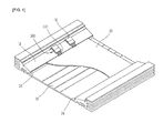
- FIG. 1 shows a configuration that the semiconductor is located outside the PCB.
- Each of power semiconductor devices 100 is installed on a semiconductor installation portion 19 of a heat sink 18 in a contact state, and bridges 110 is connected to one side of a PCB 20 in a soldering manner.
- the PCB 20 is inserted into a PCB fixing recess 24 of the heat sink 10.
- a clip type fixing device 10, as shown in FIG. 1 is separately coupled to each power semiconductor device 100 in a pressing manner to be appropriate for a specific structure of the heat sink.
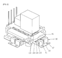
- the power semiconductor 100 located below the housing has to be fixed at the outside by a separate fixing clip 60.
- screws are inserted into fixing openings 133 formed through a semiconductor fixing piece 130 to fix the power semiconductor, and pressing pieces 65 of the fixing clip 60 which is a steel clip elastically fix the power semiconductor.
- screws inserted into clip fixing openings 67 may be separately used to fix the fixing clip 60.
- the fixing clip 60 completely covers the semiconductor, which additionally requires a hole for allowing a tool such as a driver to be inserted. This may result in a limitation of a circuit design.
- the semiconductor is located outside the PCB to couple screws for fixing the semiconductor. Or, if such structure is impossible, a hole for allowing a tool such as a driver or the like to be inserted is required. This lowers a degree of freedom in view of designing patterns of the PCB due to the position limit. In addition, bolts are required for fixing the clip, thereby increasing the number of components.
- the plastic screws are used for fixing the small semiconductor. Accordingly, such screws may be deformed due to heat generation of the semiconductor and thereby a fixing force may be weakened or lost.
- an aspect of the detailed description is to provide an integral clip type module for fixing a power semiconductor, capable of improving assembly efficiency and reducing a limit on a PCB pattern design by integrally mounting an elastic (springy) clip onto a lower surface of a housing of a plastic module to fix a semiconductor such as a diode and a MOSFET using elasticity of the clip.
- Another aspect of the detailed description is to solve problems, such as deformation, lowered fixing force and loss of screws due to heat generation of a semiconductor, by reduction of the number of required components, such as separate screws and bolts for fixing a fixing clip, and without use of a plastic screw.
- a an apparatus for fixing (fastening) a power semiconductor to a heat sink including a power semiconductor used for an inverter and a charger for an electric vehicle, a housing fixed onto a heat sink together with the power semiconductor and having a Printed Circuit Board (PCB), which is disposed on the housing, has electronic circuits thereon, such as the inverter, the charger and the like, and is connected to a bridge of the power semiconductor, which is located below the housing, via a through hole, and an elastic clip integrally mounted onto the lower surface of the housing to elastically press the lower power semiconductor so as to be fixed onto the heat sink.
- PCB Printed Circuit Board
- the elastic clip may include a plurality of U-shaped concave portions, which extends in a widthwise direction of a steel plate so as to form a plurality of pressing pieces, and a flat portion of the steel plate may form a molding portion integrally molded onto the housing.
- the present disclosure may have the following effects in the aspects of the best mode, configuration and assembling to be explained later and an operational relation.
- the present disclosure may not need a separate screw for fixing a semiconductor but integrally mount an elastic clip onto a lower surface of a housing of a plastic module so as to fixe the semiconductor, such as a diode and a MOSFET using elasticity of the clip, which may result in improvement of assembling efficiency and reduction of a limit on a pattern design of a printed circuit board.
- the number of required components, such as screws and bolts for fixing the clip may be reduced, thereby obtaining economical efficiency.
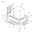
- An apparatus for fixing (fastening) a power semiconductor onto a heat sink may include a power semiconductor 100 used for an inverter and a charger for an electric vehicle, a housing 200 fixed onto a heat sink together with the power semiconductor 100 and having a Printed Circuit Board (PCB), which is disposed on the housing, has electronic circuits thereon, such as the inverter, the charger and the like, and is connected to a bridge 110 of the power semiconductor 100, which is located below the housing 200, via a through hole 230, and an elastic clip 300 integrally mounted onto the lower surface of the housing 200 to elastically press the lower power semiconductor so as to be fixed onto the heat sink.
- PCB Printed Circuit Board
- the power semiconductor 100 is located below the housing 200 and a heat sink (not shown) may be located below the power semiconductor 100.
- the power semiconductor bridge 110 may upwardly protrude through the housing 200 via the through hole 230, which is formed through the housing 200.
- the bridge 110 may connect the power semiconductor 100 to a PCB (not shown) included in the inverter, the charger or the like, located thereon.
- a scheme for connecting such type of full bridge module to the heat sink is employed from a typical connecting method for the inverter and the charger. Thus, detailed description of the scheme will be omitted.
- the fixing method of the power semiconductor using the elastic clip may be applied to a molding package, such as a Power Factor Corrector (PFC) module and a full bridge module.
- a molding package such as a Power Factor Corrector (PFC) module and a full bridge module.
- PFC Power Factor Corrector
- the fixing method using the power semiconductor fixing apparatus may be implemented such that the power semiconductor 100 located below the housing 200 is fixed onto the heat sink located therebelow in a contact state.
- the power semiconductor 100 may include a fixing element 130 protruding to one side thereof to be fixed onto the heat sink, and be integrally fixed onto the lower heat sink via a fixing opening 133 of the fixing element 130.
- the housing 200 which fixes the power semiconductor 100 with downwardly pressing it, may include a housing fixing opening 210 by which the housing 200 is fixed onto the heat sink.
- the apparatus according to the present invention may include the elastic clip 300 for fixing the power semiconductor 100 onto the heat sink with elastically pressing the power semiconductor 100.
- the elastic clip 100 may be located between the housing 200 and the power semiconductor 100 and integrally attached onto the lower surface of the housing 200.
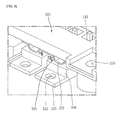
- FIG. 4 is a view showing an operation of fixing the lower power semiconductor 100 by pressing it with the elastic clip 300 formed on the lower surface of the housing 200.
- FIG. 5 shows a shape of the elastic clip 300 and coupling of the elastic clip 300 onto the lower surface of the housing 200.
- the elastic clip 300 may be formed of a steel plate having concave portions curved downwardly. Such elastic clip 300 may be integrally coupled to the lower surface of the housing 200.
- the elastic clip 300 may be formed of a steel plate or a plastic panel, which has wavy convex-concave shapes in a widthwise direction.
- convex portions may be integrally coupled onto the housing 200 by an adhesive agent or molded onto the housing 200.
- the concave portions may form pressing pieces 330 for fixedly pressing the lower power semiconductor 100.
- the elastic clip 300 may have concave portions concaved in a widthwise direction on a steel plate or plastic panel which has a flat surface.
- the concave portion may implement the pressing piece 330.
- the flat portion may form a molding portion 350 integrally coupled onto the lower surface of the housing 200.
- the pressing pieces 330 of the elastic clip 300 are a plurality of U-shaped concave portions extending in the widthwise direction of the steel plate and may be installed on a plurality of positions, especially, on positions corresponding to positions of the power semiconductors 100 fixed onto the lower surface of the elastic clip 300.
- the flat portion of the steel plate may be formed as the molding portion 350, which is integrally molded onto the housing or integrally coupled onto the housing by means of an adhesive agent.
- the elastic clip 300 may be preferably integrally installed onto the lower surface of the plastic housing 200 in a molding manner. Alternatively, the elastic clip 300 may be integrally installed by use of the adhesive agent.
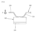
- FIG. 6 is an elevation view showing that the pressing piece 330 of the elastic clip 300 fixes the power semiconductor 100 by downwardly pressing the power semiconductor 100.
- a force P is downwardly applied onto the housing 200.
- the pressing piece 330 of the elastic clip 300 is then closely adhered onto the power semiconductor 100 such that the power semiconductor 100 is fixed onto the heat sink. This may allow for designing a package type full bridge module even without a separate power semiconductor fixing apparatus.
- the power semiconductor 100 is closely adhered onto the heat sink with being pressed by the elastic clip 300 located on the power semiconductor 100.
- This structure may allow the power semiconductor device to be assembled onto the heat sink in the closely adhered state without a separate coupling element such as screws or the like. Accordingly, the number of components such as bolts or the like may be reduced so as to reduce a fabricating cost and the assembling operation may be facilitated.
- plastic coupling bolts are used, deformation of the bolts or a loss of fixing force may be caused due to heat generation by the semiconductor.
- problems can be overcome.
- enhancement of the degree of freedom for the installation position of the semiconductor may result in overcoming a position limit, thereby enhancing a degree of freedom for a pattern design for the PCB.
Landscapes
- Physics & Mathematics (AREA)
- Thermal Sciences (AREA)
- Engineering & Computer Science (AREA)
- Microelectronics & Electronic Packaging (AREA)
- Cooling Or The Like Of Semiconductors Or Solid State Devices (AREA)
- Cooling Or The Like Of Electrical Apparatus (AREA)
Applications Claiming Priority (1)
| Application Number | Priority Date | Filing Date | Title |
|---|---|---|---|
| KR1020110100899A KR101228841B1 (ko) | 2011-10-04 | 2011-10-04 | 일체형 탄성클립을 이용한 전력용반도체 고정장치 |
Publications (1)
| Publication Number | Publication Date |
|---|---|
| EP2579306A2 true EP2579306A2 (de) | 2013-04-10 |
Family
ID=46939544
Family Applications (1)
| Application Number | Title | Priority Date | Filing Date |
|---|---|---|---|
| EP12183512.8A Withdrawn EP2579306A2 (de) | 2011-10-04 | 2012-09-07 | Federklemmvorrichtung zur Befestigung eines Leistungshalbleiters |
Country Status (5)
| Country | Link |
|---|---|
| US (1) | US9030825B2 (de) |
| EP (1) | EP2579306A2 (de) |
| JP (1) | JP5711191B2 (de) |
| KR (1) | KR101228841B1 (de) |
| CN (1) | CN103037658B (de) |
Cited By (2)
| Publication number | Priority date | Publication date | Assignee | Title |
|---|---|---|---|---|
| US11063495B2 (en) | 2019-07-01 | 2021-07-13 | Nidec Motor Corporation | Heatsink clamp for multiple electronic components |
| FR3143846A1 (fr) * | 2022-12-19 | 2024-06-21 | Valeo Eautomotive France Sas | Équipement électrique |
Families Citing this family (8)
| Publication number | Priority date | Publication date | Assignee | Title |
|---|---|---|---|---|
| KR200484015Y1 (ko) * | 2013-09-12 | 2017-07-20 | 엘에스산전 주식회사 | 전력 변환 장치 |
| US9584038B2 (en) * | 2014-06-02 | 2017-02-28 | Enphase Energy, Inc. | Ungrounded inverter enclosure and cabling |
| US9655280B1 (en) * | 2015-12-31 | 2017-05-16 | Lockheed Martin Corporation | Multi-directional force generating line-replaceable unit chassis by means of a linear spring |
| KR101823939B1 (ko) | 2017-05-12 | 2018-01-31 | 주식회사 아이투알테크 | 발열소자의 방열장치 |
| CN109428497B (zh) * | 2017-08-23 | 2020-09-18 | 台达电子企业管理(上海)有限公司 | 电源模块的组装结构及其组装方法 |
| CN111799988B (zh) * | 2019-11-19 | 2021-07-06 | 重庆金康新能源汽车有限公司 | 用于电动车辆的功率转换器的半桥模块 |
| CN113257712A (zh) * | 2021-05-11 | 2021-08-13 | 扬州台科电子有限公司 | 一种igbt模块封装结构的固定装置 |
| EP4095900B1 (de) | 2021-05-28 | 2024-01-31 | Hitachi Energy Ltd | Klemmelement und verfahren zur herstellung eines leistungshalbleiterbauelements |
Family Cites Families (37)
| Publication number | Priority date | Publication date | Assignee | Title |
|---|---|---|---|---|
| US5130888A (en) * | 1984-05-31 | 1992-07-14 | Thermalloy Incorporated | Spring clip fastener for surface mounting of printed circuit board components |
| US4890196A (en) * | 1986-03-24 | 1989-12-26 | Thermalloy Incorporated | Solderable heat sink fastener |
| US4923179A (en) * | 1987-11-02 | 1990-05-08 | Chrysler Corporation | Spring panel heat sink for electrical components |
| US5377078A (en) * | 1993-01-26 | 1994-12-27 | Relm Communications Inc. | Apparatus mounting a power semiconductor to a heat sink |
| DE59406013D1 (de) * | 1993-06-07 | 1998-06-25 | Melcher Ag | Befestigungsvorrichtung für halbleiter-schaltelemente |
| KR100199279B1 (ko) | 1996-12-09 | 1999-07-01 | 김충환 | 전력용 반도체 모듈 |
| CA2282644A1 (en) * | 1997-02-27 | 1998-09-03 | John Cennamo | Spring clip for attaching an electronic component to a heat sink and an assembly utilizing the same |
| US5896270A (en) * | 1997-05-21 | 1999-04-20 | Artesyn Technologies, Inc. | Heat sink spring clip |
| JPH10335579A (ja) | 1997-05-27 | 1998-12-18 | Toshiba Corp | 大電力半導体モジュール装置 |
| US6043981A (en) * | 1997-11-13 | 2000-03-28 | Chrysler Corporation | Heat sink assembly for electrical components |
| US6049459A (en) * | 1997-11-17 | 2000-04-11 | Lucent Technologies, Inc. | Nesting clamps for electrical components |
| US6465728B1 (en) * | 1998-03-06 | 2002-10-15 | Rockwell Automation Technologies, Inc. | Spring clip for electronic device and heat sink assembly |
| TW392869U (en) * | 1998-09-04 | 2000-06-01 | Hon Hai Prec Ind Co Ltd | Heat sink for chips |
| US6392887B1 (en) * | 1999-12-14 | 2002-05-21 | Intel Corporation | PLGA-BGA socket using elastomer connectors |
| US6892796B1 (en) * | 2000-02-23 | 2005-05-17 | General Motors Corporation | Apparatus and method for mounting a power module |
| EP1128432B1 (de) * | 2000-02-24 | 2016-04-06 | Infineon Technologies AG | Befestigung von Halbleitermodulen an einem Kühlkörper |
| US6490162B2 (en) * | 2000-08-24 | 2002-12-03 | International Rectifier Corporation | Heatsink retainer |
| US6816375B2 (en) * | 2001-08-03 | 2004-11-09 | Texas Instruments Incorporated | Heat sink attachment |
| US6600652B2 (en) * | 2001-09-28 | 2003-07-29 | Intel Corporation | Package retention module coupled directly to a socket |
| US6587344B1 (en) * | 2002-02-13 | 2003-07-01 | Power-One, Inc. | Mounting system for high-voltage semiconductor device |
| TWM247880U (en) * | 2002-05-07 | 2004-10-21 | Delta Electronics Inc | Assembling fastener of heat sink |
| US6633485B1 (en) * | 2002-11-20 | 2003-10-14 | Illinois Tool Works Inc. | Snap-in heat sink for semiconductor mounting |
| US6992893B2 (en) * | 2003-01-10 | 2006-01-31 | Hewlett-Packard Development Company, L.P. | Heat sink attachment |
| US6885557B2 (en) * | 2003-04-24 | 2005-04-26 | Intel Corporaiton | Heatsink assembly |
| TWM246689U (en) * | 2003-10-31 | 2004-10-11 | Hon Hai Prec Ind Co Ltd | Heat dissipation assembly |
| JP2006156711A (ja) * | 2004-11-30 | 2006-06-15 | Mitsubishi Electric Corp | パワー半導体モジュールの冷却システム |
| US7723844B2 (en) * | 2007-01-24 | 2010-05-25 | Fu Zhun Precision Industry (Shen Zhen) Co., Ltd. | Heat dissipation device having a locking device |
| DE102007014789B3 (de) | 2007-03-28 | 2008-11-06 | Ixys Ch Gmbh | Anordnung mindestens eines Leistungshalbleitermoduls und einer Leiterplatte und Leistungshalbleitermodul |
| US9373563B2 (en) * | 2007-07-20 | 2016-06-21 | Infineon Technologies Ag | Semiconductor assembly having a housing |
| JP5014016B2 (ja) * | 2007-08-08 | 2012-08-29 | 三菱電機株式会社 | 半導体装置 |
| US7746653B2 (en) * | 2008-01-02 | 2010-06-29 | Harman International Industries Incorporated | Clamp for electrical devices |
| US7763970B2 (en) * | 2008-02-27 | 2010-07-27 | Infineon Technologies Ag | Power module |
| US7919854B2 (en) * | 2008-08-15 | 2011-04-05 | Infineon Technologies Ag | Semiconductor module with two cooling surfaces and method |
| JP5309901B2 (ja) * | 2008-11-04 | 2013-10-09 | ダイキン工業株式会社 | 取付構造 |
| DE102008061489A1 (de) * | 2008-12-10 | 2010-06-17 | Siemens Aktiengesellschaft | Stromrichtermodul mit gekühlter Verschienung |
| JP4797077B2 (ja) * | 2009-02-18 | 2011-10-19 | 株式会社日立製作所 | 半導体パワーモジュール、電力変換装置、および、半導体パワーモジュールの製造方法 |
| US8446726B2 (en) * | 2010-10-28 | 2013-05-21 | Infineon Technologies Ag | Semiconductor module having an insert and method for producing a semiconductor module having an insert |
-
2011
- 2011-10-04 KR KR1020110100899A patent/KR101228841B1/ko not_active Expired - Fee Related
-
2012
- 2012-09-05 JP JP2012194819A patent/JP5711191B2/ja not_active Expired - Fee Related
- 2012-09-07 EP EP12183512.8A patent/EP2579306A2/de not_active Withdrawn
- 2012-09-12 CN CN201210337763.6A patent/CN103037658B/zh not_active Expired - Fee Related
- 2012-09-13 US US13/615,583 patent/US9030825B2/en not_active Expired - Fee Related
Non-Patent Citations (1)
| Title |
|---|
| None |
Cited By (2)
| Publication number | Priority date | Publication date | Assignee | Title |
|---|---|---|---|---|
| US11063495B2 (en) | 2019-07-01 | 2021-07-13 | Nidec Motor Corporation | Heatsink clamp for multiple electronic components |
| FR3143846A1 (fr) * | 2022-12-19 | 2024-06-21 | Valeo Eautomotive France Sas | Équipement électrique |
Also Published As
| Publication number | Publication date |
|---|---|
| US20130083486A1 (en) | 2013-04-04 |
| JP2013080910A (ja) | 2013-05-02 |
| CN103037658A (zh) | 2013-04-10 |
| KR101228841B1 (ko) | 2013-02-04 |
| US9030825B2 (en) | 2015-05-12 |
| JP5711191B2 (ja) | 2015-04-30 |
| CN103037658B (zh) | 2016-03-30 |
Similar Documents
| Publication | Publication Date | Title |
|---|---|---|
| US9030825B2 (en) | Springy clip type apparatus for fastening power semiconductor | |
| CN108702856B (zh) | 电路构成体 | |
| US7817426B2 (en) | Heatsink for heat-producing device | |
| EP2706828B1 (de) | Kupplungsanordnung für Leistungshalbleitervorrichtung und Leiterplatte sowie Verfahren zur Herstellung davon | |
| US10880989B2 (en) | Electrical junction box | |
| CN104470346B (zh) | 功率变换器 | |
| US8134836B2 (en) | Packaged heat dissipating assembly for an intermediate bus converter | |
| JP2012200071A (ja) | モータ制御装置 | |
| EP4350969A1 (de) | Sammelschienenwärmeableitungsstruktur und wechselrichtervorrichtung | |
| US20100110641A1 (en) | Power supply apparatus | |
| KR20210044651A (ko) | 컨버터 | |
| JP4662033B2 (ja) | Dc−dcコンバータ | |
| JP6662911B2 (ja) | 電力変換装置 | |
| JP2002076661A (ja) | 電子機器 | |
| JP2013188010A (ja) | 絶縁型スイッチング電源装置 | |
| JP2009033902A (ja) | パワーモジュール | |
| CN220191313U (zh) | 用于电子元件的散热装置、电力转换器及车辆 | |
| CN105191495A (zh) | 感应加热烹调器 | |
| JP2005072249A (ja) | 半導体ディスクリート部品の固定方法及びディスクリート半導体装置 | |
| CN216852828U (zh) | 一种高效可靠半导体安装组件 | |
| KR20000011078U (ko) | 전자제품의 발열부품용 방열장치 | |
| JP2007305809A (ja) | トランスの取り付け構造 | |
| CN119183268A (zh) | 用于电子元件的散热装置、电力转换器及车辆 | |
| JP2020022235A (ja) | 電力変換装置及びバスバ | |
| WO2025032484A1 (en) | Electronic power conversion appliance for electric or hybrid vehicles |
Legal Events
| Date | Code | Title | Description |
|---|---|---|---|
| PUAI | Public reference made under article 153(3) epc to a published international application that has entered the european phase |
Free format text: ORIGINAL CODE: 0009012 |
|
| AK | Designated contracting states |
Kind code of ref document: A2 Designated state(s): AL AT BE BG CH CY CZ DE DK EE ES FI FR GB GR HR HU IE IS IT LI LT LU LV MC MK MT NL NO PL PT RO RS SE SI SK SM TR |
|
| AX | Request for extension of the european patent |
Extension state: BA ME |
|
| STAA | Information on the status of an ep patent application or granted ep patent |
Free format text: STATUS: THE APPLICATION HAS BEEN WITHDRAWN |
|
| 18W | Application withdrawn |
Effective date: 20170727 |