EP2579112B1 - Regulating device - Google Patents
Regulating device Download PDFInfo
- Publication number
- EP2579112B1 EP2579112B1 EP11184055.9A EP11184055A EP2579112B1 EP 2579112 B1 EP2579112 B1 EP 2579112B1 EP 11184055 A EP11184055 A EP 11184055A EP 2579112 B1 EP2579112 B1 EP 2579112B1
- Authority
- EP
- European Patent Office
- Prior art keywords
- dead band
- control device
- threshold value
- control
- band element
- Prior art date
- Legal status (The legal status is an assumption and is not a legal conclusion. Google has not performed a legal analysis and makes no representation as to the accuracy of the status listed.)
- Active
Links
- 230000001105 regulatory effect Effects 0.000 title 1
- 238000000034 method Methods 0.000 claims description 40
- 230000008569 process Effects 0.000 claims description 30
- 238000012544 monitoring process Methods 0.000 claims description 14
- 238000004590 computer program Methods 0.000 claims description 10
- 238000011144 upstream manufacturing Methods 0.000 claims description 9
- 230000006641 stabilisation Effects 0.000 claims 1
- 238000011105 stabilization Methods 0.000 claims 1
- 230000006399 behavior Effects 0.000 description 11
- 230000006870 function Effects 0.000 description 9
- 230000001052 transient effect Effects 0.000 description 9
- 238000005265 energy consumption Methods 0.000 description 7
- 230000009467 reduction Effects 0.000 description 6
- 230000009471 action Effects 0.000 description 5
- 238000010586 diagram Methods 0.000 description 5
- 230000008901 benefit Effects 0.000 description 4
- 230000009849 deactivation Effects 0.000 description 4
- 230000000694 effects Effects 0.000 description 4
- 238000004886 process control Methods 0.000 description 4
- 238000013139 quantization Methods 0.000 description 4
- 238000004088 simulation Methods 0.000 description 4
- 238000012546 transfer Methods 0.000 description 4
- 230000001419 dependent effect Effects 0.000 description 3
- 230000010355 oscillation Effects 0.000 description 3
- 230000008859 change Effects 0.000 description 2
- 238000001816 cooling Methods 0.000 description 2
- 238000010438 heat treatment Methods 0.000 description 2
- 230000006872 improvement Effects 0.000 description 2
- 238000005259 measurement Methods 0.000 description 2
- 230000004044 response Effects 0.000 description 2
- 230000001133 acceleration Effects 0.000 description 1
- 230000004913 activation Effects 0.000 description 1
- 238000004364 calculation method Methods 0.000 description 1
- 238000012937 correction Methods 0.000 description 1
- 230000006866 deterioration Effects 0.000 description 1
- 238000011161 development Methods 0.000 description 1
- 230000018109 developmental process Effects 0.000 description 1
- 230000007613 environmental effect Effects 0.000 description 1
- 230000002349 favourable effect Effects 0.000 description 1
- 230000002093 peripheral effect Effects 0.000 description 1
- 238000011002 quantification Methods 0.000 description 1
- 230000007420 reactivation Effects 0.000 description 1
- 230000000630 rising effect Effects 0.000 description 1
- 238000005070 sampling Methods 0.000 description 1
- 230000003068 static effect Effects 0.000 description 1
- 230000002123 temporal effect Effects 0.000 description 1
- 230000007704 transition Effects 0.000 description 1
- 238000010200 validation analysis Methods 0.000 description 1
Images

Classifications
-
- G—PHYSICS
- G05—CONTROLLING; REGULATING
- G05B—CONTROL OR REGULATING SYSTEMS IN GENERAL; FUNCTIONAL ELEMENTS OF SUCH SYSTEMS; MONITORING OR TESTING ARRANGEMENTS FOR SUCH SYSTEMS OR ELEMENTS
- G05B13/00—Adaptive control systems, i.e. systems automatically adjusting themselves to have a performance which is optimum according to some preassigned criterion
- G05B13/02—Adaptive control systems, i.e. systems automatically adjusting themselves to have a performance which is optimum according to some preassigned criterion electric
- G05B13/0205—Adaptive control systems, i.e. systems automatically adjusting themselves to have a performance which is optimum according to some preassigned criterion electric not using a model or a simulator of the controlled system
Definitions
- the invention relates to a control device for a process in which a Totzonenglied is connected upstream of a linear dynamic controller, according to the preamble of claim 1.
- linear dynamic controllers which, when used in a control device, can be preceded by a dead zone element, are described in the function manual " Process Control System PCS 7, PCS 7 Advanced Process Library V71 ", 03/2009
- PID controller which can be referred to as P-, PI or PD controller depending on the configuration
- ModPreCon model predictive controller
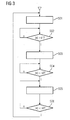
- FIG. 2 The transfer function of a dead zone element described therein is in FIG. 2 shown.
- a control difference given to the controller is formed from an effective setpoint value SP and a process value PV and is available at the output ER for the controller.
- the deadband can be activated and the lower limit zone -D (deadband) can be parameterized together with the upper zone limit D. If D is set to 0, the deadband is deactivated, but if D is not 0 then it is activated.
- the dead zone is parameterized by the user and is constant during operation. Ideally, the dead zone is parameterized in such a way that the probability of control actions is low when the controlled variable has settled within the deadband. This requires a reasonable choice of the width of the deadband.
- a dead zone element connected upstream of the controller in a control device can therefore, as is known, contribute to reducing actuator movements and thus the energy consumption and wear of the actuator. This is especially true for mechanical actuators, such as valves and pumps. Furthermore, a Totzonenglied is able to avoid continuous oscillations as working movement of an actuator, which are caused by the quantization of the control actions in the control loop.
- the use of an upstream dead zone element usually leads to a deterioration of the control quality, since the exact setpoint value is only achieved with an offset dependent on the dead zone width and not, as in the case of deleting the deadband element, by the mean value of the controlled variable.
- the offset of the controlled variable compared to the exact setpoint also means that the dead band actually selected for the reduction of setting operations is left more frequently since the deadband is symmetrical about the setpoint and not about the achieved actual value of the controlled variable.
- the controller When leaving the dead zone, the controller must again intervene to return the actual value back to the deadband, so that the above-mentioned advantages of a dead zone can be achieved only to a lesser extent.
- a control system is known in which a deadband is inserted to reduce the Stellenergy stabilities between the controller and actuator.
- the amounts of the thresholds of the deadband element are adjusted between a fixed lower limit and a variable upper limit which does not exceed a predetermined maximum value.
- the invention has for its object to provide a control device for a process in which a Totzonenglied is connected upstream of a controller, with which another Improvement of the reduction of control actions and a more favorable control behavior, in particular with regard to the stationary accuracy, can be obtained.
- the deadband member In order for the process controlled by the controller to settle on a statistical average with its controlled variable in the middle of the deadband, the deadband member is temporarily deactivated when larger deviations occur, regardless of whether they have been caused by a setpoint jump or a disturbance event.
- the dead zone element can only be activated again from a deactivated state when the control deviation undershoots a second threshold value which is less than the first threshold value at which the deactivation took place, the probability is increased that the control difference will be long within the time limit Dead zone remains and thus no further control interventions are required for a long time. This leads to reduced wear and less energy consumption, in particular of the actuator used in the control loop.
- the consumption of compressed air is proportional to the travels traveled against a spring force, if it is a single-acting pneumatic drive.
- the consumption of compressed air is proportional to the travels traveled against a spring force, if it is a single-acting pneumatic drive.
- centrifugal pumps is for each speed change energy for acceleration or Deceleration of the rotor and the moving medium required, which is consumed in each case, if there is no frequency converter with feedback of the braking energy.
- the first threshold value, at which the deadband element is automatically deactivated is set equal to the deadband limit.
- the second threshold value, below which the deadband element is again set to the active state is selected equal to 0.15 times the set deadband width.
- the calculation of this parameter can thus take place automatically as a function of the set deadband width, so that no separate input by an operator is required for this purpose either. Namely, it has been found in practice that values between 0.1 times and 0.2 times the dead band width give very good results in terms of steady-state accuracy and reduction of actuation.
- After the control deviation has fallen below the second threshold value it is advantageously possible to wait for a certain time and then again to check that this limit has been met by the control deviation in order to ensure that the process has already settled at the operating point when the deadband element is reactivated. This is achieved in an advantageous manner that the actual value of the controlled variable has stabilized almost in the middle of the dead zone. It also increases the likelihood that the actual value will remain within the dead zone for a long time without any additional control intervention.
- the course of the manipulated variable in the control device can additionally be taken into account.
- a manipulated variable is output which corresponds to an average value of the manipulated variable output in a time window in the deactivated state of the deadband element. If the second threshold value is undershot and the deadband element is reactivated, then the control variable currently calculated by the controller is not used for the future time while remaining in the dead zone, but the mean value of the manipulated variable output in the steady state.
- the manipulated variable typically performs a small working movement in the previous operation with the deadband element deactivated, an instantaneous value of the manipulated variable picked out rather randomly when changing to the activated state would generally be less suitable for keeping the controlled variable in the vicinity of the setpoint than the mean value in the steady state State output manipulated variable.
- the controlled variable oscillates in the middle rather than at the edges of the dead zone. As a result, unnecessary shifts of the mean value of the controlled variable from the desired value and thus a poor steady control quality are avoided.
- control performance monitoring CPM
- various parameters of the new control device can be derived from parameters already calculated in the monitoring module.
- CPM control performance monitoring
- the standard deviation of the controlled variable at the operating point can be used to calculate the dead zone width.
- a sliding time window is used in the monitoring module, which can serve as an indication of the duration of transient events, d. H. for the time to wait before reactivating the deadband.
- the mean value of the manipulated variable in the sliding time window is calculated in the known monitoring module CPM, which can be adopted as a value for the manipulated variable when reactivating the dead zone member.
- the controller is taken for a sampling cycle in the tracking mode with this manipulated value and then used the known in controllers of the process control system PCS7 bumpless manual / automatic switching.
- a method of controlling a process that may be performed with the controller is preferably implemented in software or a combination of software / hardware, such that the invention also relates to a computer program with computer executable program code instructions for implementing the method.
- the invention also relates to a computer program product, in particular a data carrier or a storage medium, with a computer program executable by a computer.
- a computer program is preferably part of an automation device, by which the control device is realized, or is kept in a memory of the automation device or can be loaded into this memory, so that during operation of the programmable controller this automatically executes the process for the regulation of the process.
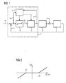
- FIG. 1 shows a block diagram with various functional blocks from which a control device 1 may be constructed, which acts with the aid of an actuator 3 to a process 2.
- the actuator 3 may be, for example, a valve, in the process 2 a pipe to which the mass flow is to be set as a controlled variable x after specification of a desired value w.
- the exact setting of the desired value w is made difficult by disturbances z, which may be pressure fluctuations in the pipe 2, for example.
- a control deviation e calculated as a difference of the setpoint value w and values of the controlled variable x is guided in the control device 1 to a dead zone element 4 and a control device 5.
- the Totzonenglied 4 is automatically activated and deactivated.
- the dead zone element 4 delivers an output quantity e1 which corresponds to the control deviation e.
- the control deviation e is in accordance with the transfer function according to FIG. 2 corrected form as output e1 given to a downstream controller 6, for example, a PID controller which generates a manipulated variable u for the actuator 3.
- a monitoring module integrated which, like the well-known Control Performance Monitoring, determines various parameters for the control behavior.
- various parameters of the control device are determined automatically or by correction with factors to be entered manually: a first threshold beyond which the Totzonenglied 4 is automatically deactivated by the controller 5, a second threshold, below which the Totzonenglied 4 is automatically re-activated , the width D ( FIG. 2 ) of the dead zone of the dead zone member 4, a time period which is waited for the re-activation of the deadband 4 after the deviation has fallen below the second threshold in the deactivated state of the deadband 4 for the first time, and the width of a time window, above which the mean value of the manipulated variable u is considered for determining a value of the manipulated variable u to be output by the controller 6 when the deadband element 4 is activated again.
- the control device 1 can be realized for example by a new controller function block, which is implemented on the basis of the known PID controller or the known model predictive controller of the process control system PCS 7 essentially by extension to the new control device 5.
- the new method for controlling a process begins with a step S01, in which the dead zone element is set to the active state. (In another embodiment, of course, could be entered before a later deactivation of the deadband in the sequence.) After the deadband was activated, there is a check of the deviation e on exceeding the first threshold s1 in a query S02. As long as the threshold s1 is not exceeded, the dead zone member remains in the activated state. This branch is marked with an "n".
- the amount of the control deviation e leaves the deadband, then it becomes appropriate a branch marked with "j" has been moved to a step S03 and put the dead zone member in the deactive state.
- the deactive state - as if no deadband 4 the controller 6 ( FIG. 1 ) - the uncorrected control deviation e is applied to the controller input in order to achieve improved transient response and better steady-state accuracy.
- the control variable is again brought very close to the desired value and the control deviation e thus falls below a second threshold value s2, this is determined by a query S04 and transferred to an action S05, in which a certain time is waited, the duration of a transient of the Control circuit corresponds.
- a subsequent query S06 it is again checked whether the control deviation e is less than the second threshold value s2, ie whether the process has settled at the operating point. If this is the case, the process jumps back to the beginning of the method and the dead zone member is activated again in step S01. If the process has not yet settled, the process returns to step S05 and the completion of a transient process is awaited.
- the abscissa represents the respective time, and the ordinate the temperature T in ° C.
- the FIGS. 4 to 6 are gradients 41, 51 and 61 of the setpoint, gradients 42, 52 and 62 of the actual value of the controlled variable and gradients 43, 53 and 63 of the control variable drawn.
- the simulated setpoint jumps are between 70 ° C and 150 ° C.
- the curves 43, 53 and 63 of the manipulated variable briefly reach a predetermined manipulated variable limit.
- FIG. 4 shows the result of a simulation in which the deadband is constantly deactivated, ie a control without dead zone.
- the setpoint value is well achieved on average by the actual value, but because of the disturbance, many adjustment interventions are required, which is visible at significant fluctuations in the course of the manipulated variable. Due to the permanent actuator movements much operating energy is consumed for the actuator even in the stationary state. In addition, the wear of the actuator due to the constant control interventions is significant.
- FIG. 5 shown simulation results of a control with a constant dead zone, ie a control device in which the Totzonenglied is constantly put into the active state, however, show even in the steady state a permanent deviation between the setpoint and actual value, but no more manipulated variable changes from a certain state, which corresponds to the occurrence of the control deviation in the dead zone after the transient process.
- the transient process itself takes a little longer than the reference FIG. 4 explained control without deadband.
- the manipulated variable thus calms down in the stationary state, but the leadership behavior is bad and the actual value of the controlled variable settles more at the edge of the deadband and not on the setpoint.
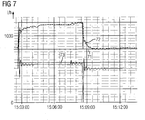
- the new controller was also successfully tested on a real plant model with a PID controller and a model predictive controller.
- a PID flow regulator with a dead zone of 30 1 / h at an operating point of 1200 1 / h and the first channel of the multi-channel model predictive controller with 3x3 structure, which regulates the reactor level and the two feeds, a dead zone of 3 was % based on the total level of 100% used.
- the abscissa represents the time, and the ordinate the flow in 1 / h.
- a plot 71 of the set point shows a jump of 200 1 / h up near the beginning of the recording period and an equally high jump downwards in the middle.
- curves 72 and 73 are plotted for actual value of the controlled variable or manipulated variable.
- the dead zone member which is upstream of the flow regulator, is temporarily deactivated shortly before the second setpoint step, which is done downwards.
- the second setpoint step which is done downwards.
- the temporary deactivation of the dead zone element during the jump down improves the guiding behavior and reduces the remaining control deviation.
- the significant improvement in the control quality is confirmed by the temporary deactivation of Totzonenglieds while reducing the control interventions in the validation of a real system.
Landscapes
- Engineering & Computer Science (AREA)
- Health & Medical Sciences (AREA)
- Artificial Intelligence (AREA)
- Computer Vision & Pattern Recognition (AREA)
- Evolutionary Computation (AREA)
- Medical Informatics (AREA)
- Software Systems (AREA)
- Physics & Mathematics (AREA)
- General Physics & Mathematics (AREA)
- Automation & Control Theory (AREA)
- Feedback Control In General (AREA)
Description
Die Erfindung betrifft eine Regeleinrichtung für einen Prozess, in welcher ein Totzonenglied einem linearen dynamischen Regler vorgeschaltet ist, gemäß dem Oberbegriff des Anspruchs 1.The invention relates to a control device for a process in which a Totzonenglied is connected upstream of a linear dynamic controller, according to the preamble of claim 1.
Als lineare dynamische Regler, welchen bei ihrer Verwendung in einer Regeleinrichtung ein Totzonenglied vorschaltbar ist, sind aus dem Funktionshandbuch "
Primär richtet sich die Breite der Totzone nach der verfahrenstechnisch gewünschten Präzision der Regelung, d. h. nach den maximal zulässigen, bleibenden Regelabweichungen, und eventuell, z. B. wenn ein schaltendes Stellglied verwendet wird, nach der Änderung der Regelgröße bei der minimal möglichen Änderung der Stellgröße. Im Hinblick auf die Minimierung von Stelleingriffen helfen die folgenden Einstellregeln dabei, die Totzone so breit zu wählen, dass eine Varianz der Regelgröße, die beispielsweise aufgrund von Messrauschen oder Quantisierungsrauschen unvermeidlich ist, nicht zu häufigen Stellbewegungen führt:
- Unter der Annahme einer statistischen Normalverteilung der Werte der Regelgröße um den Sollwert wird als Breite der Totzone das Zwei- bis Dreifache der Standardabweichung der Regelgröße im stationären Zustand verwendet. Falls die Regeleinrichtung mit einem Überwachungsbaustein zur Bestimmung von Kenngrößen für das Regelverhalten ausgestattet ist, der im eingangs genannten Funktionshandbuch auch als Control Performance Management (CPM) oder ConPerMon bezeichnet wird, kann die im Überwachungsbaustein berechnete Standardabweichung des Istwerts zur Berechnung der Totzonenbreite herangezogen werden.
- Falls Veränderungen der Regelgröße durch eine Quantisierung der Stellgröße nur schrittweise erfolgen, z. B. wegen einer Pulsbreitenmodulation mit definierter Mindestimpulsdauer, wegen eines Schrittreglers mit definierter Mindestschrittweite oder bei einem elektropneumatischen Stellungsregler mit Haftreibung in der Stopfbuchse des pneumatischen Antriebs, richtet sich die Breite der Totzone nach der Stellgrößenquantisierung, die mit der jeweiligen Prozessverstärkung zu multiplizieren ist. Beispielsweise bei einer Temperaturregelung mit einer Stellgrößenquantifizierung von 5 % und einer Prozessverstärkung von 1,5 °C/% können nur Temperaturen in einem Raster von

- Assuming a statistical normal distribution of the values of the controlled variable around the setpoint value, the width of the dead zone is used to be two to three times the standard deviation of the controlled variable in the stationary state. If the control device is equipped with a monitoring module for determining characteristic values for control behavior, which is also referred to as Control Performance Management (CPM) or ConPerMon in the function manual mentioned in the introduction, the standard deviation of the actual value calculated in the monitoring module can be used to calculate the dead zone width.
- If changes in the controlled variable by a quantization of the manipulated variable only gradually, z. B. because of a pulse width modulation with a defined minimum pulse duration, because of a stepper with a defined minimum increment or an electropneumatic positioner with static friction in the stuffing box of the pneumatic drive, the width of the dead zone is based on the manipulated variable quantization, which is to be multiplied by the respective process gain. For example, with a temperature control with a manipulated variable quantification of 5% and a process gain of 1.5 ° C /%, only temperatures in a grid of
Mit einer Totzone konstanter Breite wird zwar bereits eine gewisse Reduktion der Stelleingriffe erreicht, aber es müssen einige Nachteile in Kauf genommen werden:
- Regelabweichungen, die kleiner als die Totzone sind, werden vom Regler ignoriert, d. h. der Regler regelt diese nicht aus, auch wenn er es ohne vorgeschaltete Totzone könnte. Daher können sich stationäre Zustände des Istwerts der Regelgröße einstellen, deren zeitlicher Mittelwert deutlich vom Sollwert abweicht.
- Wenn sich stationäre Zustände in den Randbereichen der Totzone einstellen, kann es bereits bei kleinsten Störungen immer wieder zu einem Regeleingriff kommen. Nach einem Störereignis, welches zum Verlassen der Totzone führt, bringt der Regler nämlich den Istwert der Regelgröße nur bis zum jeweiligen Rand der Totzone zurück, was bei weiteren Störungen zu erneuten Stelleingriffen führen kann. Dadurch werden Verschleiß und Energieverbrauch des Stellglieds erhöht.
- Insbesondere große Totzonen wirken sich negativ auf das Führungsverhalten des Regelkreises bei Sollwertsprüngen aus. Grund dafür ist, dass der Regler beispielsweise in der Anstiegsphase einer positiven Sprungantwort beim Eintritt der Regeldifferenz in die Totzone zunächst ,"die Arbeit einstellt". Dies kann zu einem kriechenden Einschwingvorgang führen oder dazu, dass der Regler erst wieder aktiv wird, wenn der Istwert aufgrund eines Überschwingers die obere Grenze der Totzone überschreitet.
- Deviations that are smaller than the deadband are ignored by the controller, ie the controller does not control these, even if it could without upstream Deadband. Therefore, stationary states of the actual value of the control variable can be set, the time average deviates significantly from the setpoint.
- If steady state conditions occur in the peripheral areas of the deadband, a control intervention can occur again and again even with the smallest disturbances. After a disturbance event, which leads to the deadband, the controller brings namely the actual value of the controlled variable only back to the respective edge of the dead zone, which can lead to further disturbances in further disturbances. This increases wear and energy consumption of the actuator.
- Large dead zones, in particular, have a negative effect on the control behavior of the control loop during setpoint jumps. The reason for this is that, for example, in the rising phase of a positive step response when the control difference enters the dead zone, the controller first "stops work". This can lead to a creeping transient or to the fact that the controller only becomes active again when the actual value exceeds the upper limit of the dead zone due to an overshoot.
Ein dem Regler in einer Regeleinrichtung vorgeschaltetes Totzonenglied kann also bekanntermaßen dazu beitragen, Stellgliedbewegungen und damit den Energieverbrauch und den Verschleiß des Stellglieds zu reduzieren. Dies gilt insbesondere für mechanische Stellglieder, beispielsweise Ventile und Pumpen. Weiterhin ist ein Totzonenglied in der Lage, Dauerschwingungen als Arbeitsbewegung eines Stellglieds, welche durch die Quantisierung der Stelleingriffe hervorgerufen werden, im Regelkreis zu vermeiden.A dead zone element connected upstream of the controller in a control device can therefore, as is known, contribute to reducing actuator movements and thus the energy consumption and wear of the actuator. This is especially true for mechanical actuators, such as valves and pumps. Furthermore, a Totzonenglied is able to avoid continuous oscillations as working movement of an actuator, which are caused by the quantization of the control actions in the control loop.
Ein Einsatz eines vorgeschalteten Totzonenglieds führt jedoch bisher meist zu einer Verschlechterung der Regelgüte, da der exakte Sollwert nur mit einem von der Totzonenbreite abhängigen Offset erreicht wird und nicht, wie bei Weglassen des Totzonenglieds, durch den Mittelwert der Regelgröße. Der Versatz (Offset) der Regelgröße gegenüber dem exakten Sollwert führt zudem dazu, dass die eigentlich zur Reduktion von Stelleingriffen gewählte Totzone häufiger verlassen wird, da die Totzone symmetrisch um den Sollwert und nicht um den erreichten Istwert der Regelgröße liegt. Bei Verlassen der Totzone muss der Regler erneut eingreifen, um den Istwert wieder in den Bereich der Totzone zurückzuführen, so dass die oben genannten Vorteile einer Totzone nur in einem geringeren Umfang erreicht werden können.However, the use of an upstream dead zone element usually leads to a deterioration of the control quality, since the exact setpoint value is only achieved with an offset dependent on the dead zone width and not, as in the case of deleting the deadband element, by the mean value of the controlled variable. The offset of the controlled variable compared to the exact setpoint also means that the dead band actually selected for the reduction of setting operations is left more frequently since the deadband is symmetrical about the setpoint and not about the achieved actual value of the controlled variable. When leaving the dead zone, the controller must again intervene to return the actual value back to the deadband, so that the above-mentioned advantages of a dead zone can be achieved only to a lesser extent.
Diese Probleme führen dazu, dass Totzonenglieder linearen dynamischen Reglern häufig nur in solchen Fällen vorgeschaltet werden, in denen sie unbedingt notwendig sind, und meist nicht in Fällen, in welchen allein der Verschleiß und Energieverbrauch einer prozesstechnischen Anlage, in welcher die Regeleinrichtung angewendet wird, reduziert werden sollen.These problems mean that dead zone elements are frequently preceded by linear dynamic controllers only in cases in which they are absolutely necessary, and usually not in cases in which only the wear and energy consumption of a process plant in which the control device is used is reduced should be.
Aus der
In der
Der Erfindung liegt die Aufgabe zugrunde, eine Regeleinrichtung für einen Prozess, in welcher ein Totzonenglied einem Regler vorgeschaltet ist, zu schaffen, mit welcher eine weitere Verbesserung der Reduktion von Stelleingriffen und ein günstigeres Regelverhalten, insbesondere bezüglich der stationären Genauigkeit, erhalten werden können.The invention has for its object to provide a control device for a process in which a Totzonenglied is connected upstream of a controller, with which another Improvement of the reduction of control actions and a more favorable control behavior, in particular with regard to the stationary accuracy, can be obtained.
Zur Lösung dieser Aufgabe weist die neue Regeleinrichtung der eingangs genannten Art die im kennzeichnenden Teil des Anspruchs 1 angegebenen Merkmale auf. In den abhängigen Ansprüchen sind vorteilhafte Weiterbildungen der Erfindung, in Anspruch 7 ein Regelungsverfahren, in den Ansprüchen 8 und 9 ein entsprechendes Computerprogramm bzw. ein Computerprogrammprodukt beschrieben.To solve this problem, the new control device of the type mentioned in the characterizing part of claim 1 features. Advantageous developments of the invention are described in the dependent claims, in claim 7 a control method, in claims 8 and 9 a corresponding computer program or a computer program product are described.
Damit der durch die Regeleinrichtung geregelte Prozess im statistischen Mittel mit seiner Regelgröße in der Mitte der Totzone einschwingt, wird das Totzonenglied vorübergehend beim Auftreten von größeren Regelabweichungen deaktiviert, und zwar unabhängig davon, ob diese durch einen Sollwertsprung oder durch ein Störereignis verursacht worden sind.In order for the process controlled by the controller to settle on a statistical average with its controlled variable in the middle of the deadband, the deadband member is temporarily deactivated when larger deviations occur, regardless of whether they have been caused by a setpoint jump or a disturbance event.
Da das Totzonenglied aus einem deaktivierten Zustand heraus erst dann wieder aktivierbar ist, wenn die Regelabweichung einen zweiten Schwellwert unterschreitet, der kleiner als der erste Schwellwert ist, bei welchem die Deaktivierung erfolgte, wird in vorteilhafter Weise die Wahrscheinlichkeit vergrößert, dass die Regeldifferenz lange innerhalb der Totzone verbleibt und somit lange keine weiteren Stelleingriffe mehr nötig werden. Dies führt zu reduziertem Verschleiß und weniger Energieverbrauch insbesondere des im Regelkreis eingesetzten Stellglieds.Since the dead zone element can only be activated again from a deactivated state when the control deviation undershoots a second threshold value which is less than the first threshold value at which the deactivation took place, the probability is increased that the control difference will be long within the time limit Dead zone remains and thus no further control interventions are required for a long time. This leads to reduced wear and less energy consumption, in particular of the actuator used in the control loop.
Zudem werden die bereits oben genannten Nachteile eines Totzonenglieds, welches nicht automatisch deaktivierbar ist, bezüglich des Führungsverhaltens bei Sollwertsprüngen, z. B. kriechendes Verhalten oder Überschwinger beim Einschwingvorgang, deutlich reduziert. Damit erhöht sich die Akzeptanz für den Einsatz von Totzonengliedern bei Anwendern, da die bisherigen negativen Auswirkungen auf die Regelgüte weitgehend vermieden werden. Somit kommen die durch die neue Regeleinrichtung realisierbaren Energieeinsparungen aufgrund reduzierter Stelleingriffe in deutlich mehr Anwendungsfällen zum Tragen. Dies gilt insbesondere für Regelkreise, in welchen mechanische Stellglieder wie Ventile oder Pumpen verwendet werden. Bei Ventilen ist der Energieverbrauch nämlich direkt abhängig von den zurückgelegten Verfahrwegen, d. h. vom zeitlichen Integral des Stellweges. Speziell bei elektropneumatisch betriebenen Stellventilen ist der Verbrauch an Druckluft proportional zu den gegen eine Federkraft zurückgelegten Verfahrwegen, wenn es sich um einen einfach wirkenden pneumatischen Antrieb handelt. Bei Kreiselpumpen ist für jede Drehzahländerung Energie zur Beschleunigung bzw. zur Abbremsung des Rotors und des mitbewegten Mediums erforderlich, die jeweils verbraucht wird, falls kein Frequenzumrichter mit Rückspeisung der Bremsenergie vorhanden ist. Bei Temperaturregelkreisen mit einer so genannten Split-Range-Regelung für Heizen oder Kühlen eines Prozessmediums in Abhängigkeit der jeweils herrschenden Regelabweichung kommt es darauf an, Schwingungen des Stellsignals zu vermeiden, die zu einem zeitlich kurz aufeinander folgenden Heizen und Kühlen führen und dadurch Energie verschwenden würden. Die mit der neuen Regeleinrichtung erzielte Reduktion von Dauerschwingungen trägt hier in besonders vorteilhafter Weise zu einer Reduktion des Energieverbrauchs bei.In addition, the above-mentioned disadvantages of a Totzonenglieds, which is not automatically deactivated, with respect to the leadership behavior in setpoint jumps, z. As creeping behavior or overshoot the transient, significantly reduced. This increases the acceptance of Totzonengliedern users, since the previous negative effects on the control quality are largely avoided. Thus, the realizable by the new control device energy savings due to reduced control interventions come in significantly more applications to fruition. This is especially true for control circuits in which mechanical actuators such as valves or pumps are used. For valves, the energy consumption is directly dependent on the traversed travel paths, ie on the temporal integral of the travel. Especially with electropneumatically operated control valves, the consumption of compressed air is proportional to the travels traveled against a spring force, if it is a single-acting pneumatic drive. For centrifugal pumps is for each speed change energy for acceleration or Deceleration of the rotor and the moving medium required, which is consumed in each case, if there is no frequency converter with feedback of the braking energy. In temperature control circuits with a so-called split-range control for heating or cooling of a process medium as a function of the prevailing control deviation, it is important to avoid oscillations of the control signal, which lead to a temporally short successive heating and cooling and thereby wasting energy , The reduction of continuous oscillations achieved with the new control device contributes in a particularly advantageous manner to a reduction in energy consumption.
In einer besonders vorteilhaften Ausgestaltung der Erfindung wird der erste Schwellwert, bei dessen Überschreiten das Totzonenglied automatisch deaktivierbar ist, gleich der Totzonengrenze gesetzt. Dadurch kann die Eingabe eines zusätzlichen Parameters bei der Inbetriebsetzung der Regeleinrichtung entfallen und somit der Aufwand der Inbetriebnahme vermindert werden. In diesem Zusammenhang soll darauf hingewiesen werden, dass die Begriffe "Totzonengrenze" und "Totzonenbreite" häufig als Synonym verwendet werden, da für die Bewertung, ob die Regelabweichung innerhalb der Totzone liegt, der Betrag der Regelabweichung herangezogen wird.In a particularly advantageous embodiment of the invention, the first threshold value, at which the deadband element is automatically deactivated, is set equal to the deadband limit. As a result, the input of an additional parameter in the commissioning of the control device can be omitted and thus the cost of commissioning can be reduced. In this context, it should be pointed out that the terms "dead zone boundary" and "dead zone width" are frequently used as a synonym, because the amount of the system deviation is used to evaluate whether the control deviation lies within the deadband.
In einer weiteren vorteilhaften Ausgestaltung wird der zweite Schwellwert, bei dessen Unterschreiten das Totzonenglied erneut in den aktiven Zustand versetzt wird, gleich dem 0,15fachen der eingestellten Totzonenbreite gewählt. Die Berechnung dieses Parameters kann somit in Abhängigkeit der eingestellten Totzonenbreite automatisch erfolgen, so dass auch hierfür keine gesonderte Eingabe durch einen Bediener erforderlich ist. Es hat sich nämlich in der Praxis gezeigt, dass Werte zwischen dem 0,1fachen und dem 0,2fachen der Totzonenbreite sehr gute Ergebnisse bezüglich der stationären Genauigkeit und der Reduktion von Stelleingriffen liefern. Nachdem die Regelabweichung den zweiten Schwellwert unterschritten hat, kann vorteilhaft noch eine gewisse Zeit abgewartet und danach erneut das Einhalten dieser Grenze durch die Regelabweichung überprüft werden, um sicherzustellen, dass sich der Prozess bei der erneuten Aktivierung des Totzonenglieds bereits am Arbeitspunkt eingeschwungen hat. Damit wird in vorteilhafter Weise erreicht, dass sich der Istwert der Regelgröße nahezu in der Mitte der Totzone stabilisiert hat. Zudem wird die Wahrscheinlichkeit erhöht, dass der Istwert ohne weitere Stelleingriffe lange innerhalb der Totzone verbleibt.In a further advantageous refinement, the second threshold value, below which the deadband element is again set to the active state, is selected equal to 0.15 times the set deadband width. The calculation of this parameter can thus take place automatically as a function of the set deadband width, so that no separate input by an operator is required for this purpose either. Namely, it has been found in practice that values between 0.1 times and 0.2 times the dead band width give very good results in terms of steady-state accuracy and reduction of actuation. After the control deviation has fallen below the second threshold value, it is advantageously possible to wait for a certain time and then again to check that this limit has been met by the control deviation in order to ensure that the process has already settled at the operating point when the deadband element is reactivated. This is achieved in an advantageous manner that the actual value of the controlled variable has stabilized almost in the middle of the dead zone. It also increases the likelihood that the actual value will remain within the dead zone for a long time without any additional control intervention.
Um bei Regelgrößenschwankungen den Mittelwert der Regelgröße möglichst nahe an den Sollwert zu bringen, kann zusätzlich der Verlauf der Stellgröße in der Regeleinrichtung berücksichtigt werden. Dazu wird nach erneuter Aktivierung des Totzonenglieds eine Stellgröße ausgegeben, welche einem Mittelwert der in einem Zeitfenster im deaktivierten Zustand des Totzonenglieds ausgegebenen Stellgröße entspricht. Wird der zweite Schwellwert unterschritten und das Totzonenglied erneut aktiviert, so wird also nicht die aktuell durch den Regler berechnete Stellgröße für die zukünftige Zeit während des Verbleibens in der Totzone verwendet, sondern der Mittelwert der im eingeschwungenen Zustand ausgegebenen Stellgröße. Da die Stellgröße im vorherigen Betrieb mit deaktiviertem Totzonenglied typischerweise eine kleine Arbeitsbewegung ausführt, wäre ein beim Wechsel in den aktivierten Zustand eher zufällig herausgegriffener Momentanwert der Stellgröße nämlich im Allgemeinen schlechter für ein Halten der Regelgröße in der Nähe des Sollwerts geeignet als der Mittelwert der im eingeschwungenen Zustand ausgegebenen Stellgröße. Damit schwingt sich in vorteilhafter Weise die Regelgröße eher in der Mitte als an den Rändern der Totzone ein. Dadurch werden unnötige Verlagerungen des Mittelwerts der Regelgröße vom Sollwert und somit eine schlechte stationäre Regelgüte vermieden.In order to bring the mean value of the controlled variable as close as possible to the setpoint in the case of controlled variable fluctuations, the course of the manipulated variable in the control device can additionally be taken into account. For this purpose, after a renewed activation of the deadband element, a manipulated variable is output which corresponds to an average value of the manipulated variable output in a time window in the deactivated state of the deadband element. If the second threshold value is undershot and the deadband element is reactivated, then the control variable currently calculated by the controller is not used for the future time while remaining in the dead zone, but the mean value of the manipulated variable output in the steady state. Since the manipulated variable typically performs a small working movement in the previous operation with the deadband element deactivated, an instantaneous value of the manipulated variable picked out rather randomly when changing to the activated state would generally be less suitable for keeping the controlled variable in the vicinity of the setpoint than the mean value in the steady state State output manipulated variable. Thus, advantageously, the controlled variable oscillates in the middle rather than at the edges of the dead zone. As a result, unnecessary shifts of the mean value of the controlled variable from the desired value and thus a poor steady control quality are avoided.
Falls die Regeleinrichtung mit einem Überwachungsbaustein zum so genannten Control Performance Monitoring (CPM) ausgestattet ist, wie er beispielsweise im Prozessleitsystem PCS 7 Verwendung findet, können verschiedene Parameter der neuen Regeleinrichtung von ohnehin im Überwachungsbaustein berechneten Kenngrößen abgeleitet werden. Das hat den Vorteil, dass die Ermittlung der Parameter besonders einfach und zuverlässig ist, da auf erprobte Teile des Überwachungsbausteins zurückgegriffen werden kann. So kann zur Bemessung der Totzonenbreite die Standardabweichung der Regelgröße im Arbeitspunkt herangezogen werden. Weiterhin wird im Überwachungsbaustein ein gleitendes Zeitfenster verwendet, welches als Anhaltspunkt für die Dauer von Einschwingvorgängen dienen kann, d. h. für die Zeit, die abgewartet werden soll, bevor die Totzone reaktiviert wird. Zudem wird in dem bekannten Überwachungsbaustein CPM der Mittelwert der Stellgröße im gleitenden Zeitfenster berechnet, der als Wert für die Stellgröße beim Reaktivieren des Totzonenglieds übernommen werden kann. Um diese Stellgröße auszugeben, wird der Regler für einen Abtastzyklus in den Nachführbetrieb mit diesem Stellwert genommen und anschließend die bei Reglern des Prozessleitsystems PCS7 bekannte stoßfreie Hand-/Automatik-Umschaltung genutzt.If the control device is equipped with a monitoring module for so-called control performance monitoring (CPM), as used for example in the PCS 7 process control system, various parameters of the new control device can be derived from parameters already calculated in the monitoring module. This has the advantage that the determination of the parameters is particularly simple and reliable, since proven parts of the monitoring module can be used. For example, the standard deviation of the controlled variable at the operating point can be used to calculate the dead zone width. Furthermore, a sliding time window is used in the monitoring module, which can serve as an indication of the duration of transient events, d. H. for the time to wait before reactivating the deadband. In addition, the mean value of the manipulated variable in the sliding time window is calculated in the known monitoring module CPM, which can be adopted as a value for the manipulated variable when reactivating the dead zone member. To output this manipulated variable, the controller is taken for a sampling cycle in the tracking mode with this manipulated value and then used the known in controllers of the process control system PCS7 bumpless manual / automatic switching.
Ein Verfahren zur Regelung eines Prozesses, welches mit der Regeleinrichtung durchgeführt werden kann, ist bevorzugt in Software oder einer Kombination von Soft-/Hardware implementiert, so dass die Erfindung auch ein Computerprogramm mit durch einen Computer ausführbaren Programmcodeanweisungen zur Implementierung des Verfahrens betrifft. In diesem Zusammenhang betrifft die Erfindung auch ein Computerprogrammprodukt, insbesondere einen Datenträger oder ein Speichermedium, mit einem durch einen Computer ausführbaren derartigen Computerprogramm. Ein solches Computerprogramm ist bevorzugt Bestandteil eines Automatisierungsgeräts, durch welches die Regeleinrichtung realisiert ist, oder wird in einem Speicher des Automatisierungsgeräts vorgehalten oder ist in diesen Speicher ladbar, so dass beim Betrieb des Automatisierungsgeräts dieses das Verfahren zur Regelung des Prozesses automatisch ausführt.A method of controlling a process that may be performed with the controller is preferably implemented in software or a combination of software / hardware, such that the invention also relates to a computer program with computer executable program code instructions for implementing the method. In this context, the invention also relates to a computer program product, in particular a data carrier or a storage medium, with a computer program executable by a computer. Such a computer program is preferably part of an automation device, by which the control device is realized, or is kept in a memory of the automation device or can be loaded into this memory, so that during operation of the programmable controller this automatically executes the process for the regulation of the process.
Anhand der Zeichnungen, in welchen ein Ausführungsbeispiel der Erfindung dargestellt ist, werden im Folgenden die Erfindung sowie Ausgestaltungen und Vorteile näher erläutert.With reference to the drawings, in which an embodiment of the invention is shown, the invention and refinements and advantages are explained in more detail below.
Es zeigen:
- Figur 1
- ein Blockschaltbild eines Regelkreises,
Figur 2- eine Übertragungsfunktion eines Totzonenglieds,
Figur 3- ein Ablaufdiagramm mit den Zustandsübergängen des Totzonenglieds,
Figuren 4 bis 7- Zeitdiagramme zur Verdeutlichung des Regelverhaltens.
- FIG. 1
- a block diagram of a control loop,
- FIG. 2
- a transfer function of a deadband member,
- FIG. 3
- a flowchart with the state transitions of the dead zone member,
- FIGS. 4 to 7
- Timing diagrams to clarify the control behavior.
Die
Anhand
Die vorteilhaften Wirkungen der verschiedenen Maßnahmen sollen zunächst anhand der Zeitdiagramme in den 
TD = 2. Auf den Istwert der Regelgröße wirkt ein farbiges Rauschsignal mit der Standardabweichung 0,5°, das aus einem weißen Rauschen mit Hilfe eines Formfilters der Übertragungsfunktion 
TD = 2. The actual value of the controlled variable is affected by a colored noise signal with the standard deviation of 0.5 °, which results from a white noise with the help of a shape filter of the transfer function
Die in
Wird nun, wie bei den in
An den
Die neue Regeleinrichtung wurde ebenso erfolgreich mit einem PID-Regler und einem modellprädiktiven Regler an einem realen Anlagenmodell erprobt. Dabei wurde ein PID-Durchflussregler mit einer Totzone von 30 1/h bei einem Arbeitspunkt von 1200 1/h und am ersten Kanal des mehrkanaligen modellprädiktiven Reglers mit 3x3-Struktur, der den Reaktor-Füllstand und die beiden Zuläufe regelt, eine Totzone von 3 % bezogen auf den Gesamtfüllstand von 100 % verwendet. In
Claims (9)
- Closed-loop control device for a process, in which a dead band element (4) is connected upstream of a linear dynamic controller (6) in order to reduce actuating interventions in the steady control state, characterized in that provision is made of means (5) which can be used to automatically deactivate the dead band element (4) if a control deviation (e) of the control loop exceeds a predefined or predefinable first threshold value (s1), a control deviation (e1) passed via the dead band element (4) not being influenced by a set dead band in the deactivated state, and which can be used to automatically activate the dead band element (4) again if the control deviation (e) undershoots a predefined or predefinable second threshold value (s2) which is less than the first threshold value (s1).
- Closed-loop control device according to Claim 1, characterized in that the first threshold value (s1) is equal to the set dead band width (D).
- Closed-loop control device according to Claim 1 or 2, characterized in that the second threshold value (s2) is equal to 0.1 to 0.2 times the set dead band width (D).
- Closed-loop control device according to one of Claims 1 to 3, characterized in that the closed-loop control device (1) is also designed in such a manner that, in the deactivated state of the dead band element (4) after the second threshold value (s2) has been exceeded by the control deviation (e), the process waits for a predefined or predefinable period and only then can the dead band element (4) be automatically activated again if the control deviation (e) is less than the second threshold value (s2).
- Closed-loop control device according to Claim 4, characterized in that the closed-loop control device (1) is also designed, after the dead band element (4) has been activated again, to output a manipulated variable (u) which corresponds to a mean value of the manipulated variable last output in a time window in the inactive state of the dead band element (4).
- Closed-loop control device according to one of the preceding claims, characterized in that the closed-loop control device (1) has a monitoring module for determining a plurality of characteristic variables for the control behavior, and in that at least one parameter of the closed-loop control device (1) is predetermined using at least one of the characteristic variables,
the width (D) of the dead band being predetermined, as the parameter, on the basis of a standard deviation of the controlled variable (x) calculated by the monitoring module, and/or
the period after which the dead band element (4) can be activated again when the second threshold value (s2) is exceeded being predetermined on the basis of a time window which is set in the monitoring module and is characteristic of the duration of stabilization processes, and/or
the mean value of the manipulated variable (u) last output in the time window in the inactive state of the dead band element (4) corresponding to the mean value of the manipulated variable (u) calculated in the monitoring module. - Method for controlling a process (2), in which a dead band element (4) is connected upstream of a linear dynamic controller (6) in order to reduce actuating interventions in the steady control state, characterized in that the dead band element (4) is automatically deactivated if a control deviation (e) of the control loop exceeds a predefined or predefinable first threshold value (s1), a control deviation (e1) passed via the dead band element (4) not being influenced by a set dead band (D) in the inactive state, and in that the dead band element (4) is automatically activated again if the control deviation (e) undershoots a predefined or predefinable second threshold value (s2) which is less than the first threshold value (s1).
- Computer program having program code instructions which can be executed by a computer and are intended to implement the method according to Claim 7 when the computer program is executed on a computer.
- Computer program product, in particular a data carrier or a storage medium, having a computer program according to Claim 8 which can be executed by a computer.
Priority Applications (3)
| Application Number | Priority Date | Filing Date | Title |
|---|---|---|---|
| EP11184055.9A EP2579112B1 (en) | 2011-10-06 | 2011-10-06 | Regulating device |
| US13/646,234 US9152134B2 (en) | 2011-10-06 | 2012-10-05 | Closed-loop control device |
| CN201210378089.6A CN103034135B (en) | 2011-10-06 | 2012-10-08 | Control device |
Applications Claiming Priority (1)
| Application Number | Priority Date | Filing Date | Title |
|---|---|---|---|
| EP11184055.9A EP2579112B1 (en) | 2011-10-06 | 2011-10-06 | Regulating device |
Publications (2)
| Publication Number | Publication Date |
|---|---|
| EP2579112A1 EP2579112A1 (en) | 2013-04-10 |
| EP2579112B1 true EP2579112B1 (en) | 2014-01-01 |
Family
ID=45065634
Family Applications (1)
| Application Number | Title | Priority Date | Filing Date |
|---|---|---|---|
| EP11184055.9A Active EP2579112B1 (en) | 2011-10-06 | 2011-10-06 | Regulating device |
Country Status (3)
| Country | Link |
|---|---|
| US (1) | US9152134B2 (en) |
| EP (1) | EP2579112B1 (en) |
| CN (1) | CN103034135B (en) |
Cited By (3)
| Publication number | Priority date | Publication date | Assignee | Title |
|---|---|---|---|---|
| EP3296820A1 (en) | 2016-09-16 | 2018-03-21 | Siemens Aktiengesellschaft | Control device and method |
| WO2018050779A1 (en) | 2016-09-16 | 2018-03-22 | Siemens Aktiengesellschaft | Control device and method |
| DE102017213893A1 (en) | 2017-08-09 | 2019-02-14 | Siemens Aktiengesellschaft | Control device and method |
Families Citing this family (6)
| Publication number | Priority date | Publication date | Assignee | Title |
|---|---|---|---|---|
| DE102013205356B4 (en) * | 2013-03-26 | 2016-07-07 | Siemens Aktiengesellschaft | Method for computer-aided control and / or regulation of a technical system |
| US9983574B2 (en) | 2013-09-30 | 2018-05-29 | United States Gypsum Company | Systems and methods for controlling a conveyor system during product changeovers |
| US10281905B2 (en) * | 2015-09-23 | 2019-05-07 | Deere & Company | Control system for agricultural equipment |
| US10234837B2 (en) * | 2015-09-28 | 2019-03-19 | Deere & Company | Adaptive performance targets for controlling a mobile machine |
| US11068000B2 (en) * | 2019-07-11 | 2021-07-20 | Johnson Controls Technology Company | Valve assembly with delay compensation for proportional variable deadband control |
| DE102020001431A1 (en) | 2020-03-05 | 2021-09-09 | KSB SE & Co. KGaA | Method for flow and / or pressure control in a hydraulic system |
Family Cites Families (5)
| Publication number | Priority date | Publication date | Assignee | Title |
|---|---|---|---|---|
| DE2528313C2 (en) * | 1975-06-25 | 1976-12-09 | Siemens Ag | PROCEDURE FOR STEP CONTROL WITH A THREE-POSITION SWITCH WITH ADJUSTABLE DEAD ZONE WIDTH |
| DE3606640A1 (en) | 1986-02-28 | 1987-10-15 | Messerschmitt Boelkow Blohm | ADAPTIVE CONTROL DEVICE WITH HIGH ACCURACY AND LOW CONTROL ENERGY CONSUMPTION |
| US7155319B2 (en) * | 2005-02-23 | 2006-12-26 | Applied Materials, Inc. | Closed loop control on liquid delivery system ECP slim cell |
| CN100462875C (en) | 2006-04-14 | 2009-02-18 | 中国科学院长春光学精密机械与物理研究所 | Control system with gap characteristic transmission mechanism |
| JP5269811B2 (en) | 2007-12-26 | 2013-08-21 | 住友重機械工業株式会社 | Hybrid construction machine and control method of hybrid construction machine |
-
2011
- 2011-10-06 EP EP11184055.9A patent/EP2579112B1/en active Active
-
2012
- 2012-10-05 US US13/646,234 patent/US9152134B2/en active Active
- 2012-10-08 CN CN201210378089.6A patent/CN103034135B/en active Active
Cited By (3)
| Publication number | Priority date | Publication date | Assignee | Title |
|---|---|---|---|---|
| EP3296820A1 (en) | 2016-09-16 | 2018-03-21 | Siemens Aktiengesellschaft | Control device and method |
| WO2018050779A1 (en) | 2016-09-16 | 2018-03-22 | Siemens Aktiengesellschaft | Control device and method |
| DE102017213893A1 (en) | 2017-08-09 | 2019-02-14 | Siemens Aktiengesellschaft | Control device and method |
Also Published As
| Publication number | Publication date |
|---|---|
| US9152134B2 (en) | 2015-10-06 |
| US20130090747A1 (en) | 2013-04-11 |
| CN103034135A (en) | 2013-04-10 |
| CN103034135B (en) | 2016-01-20 |
| EP2579112A1 (en) | 2013-04-10 |
Similar Documents
| Publication | Publication Date | Title |
|---|---|---|
| EP2579112B1 (en) | Regulating device | |
| DE3207392C2 (en) | Device for self-adapting position control of an actuator | |
| EP0431287B1 (en) | Process for optimised operation of two or more compressors in parallel or series operation | |
| DE2751743A1 (en) | METHOD AND CONTROL DEVICE FOR MEASURING FLOWING MEDIA | |
| DE102015105389A1 (en) | Position control device | |
| EP1095319B1 (en) | Method for operating a control system and device for carrying out said method | |
| EP1880096B1 (en) | Method and device for electrically actuating a valve with a mechanical closing element | |
| EP1490735B1 (en) | Method and controller for the adaptive control of at least one component of a technical plant | |
| WO1997024648A1 (en) | Method of controlling a self-compensating process subject to deceleration, and control device for carrying out the method | |
| EP0473914B1 (en) | Control system for an actuator in an internal combustion engine | |
| DE102005002385A1 (en) | Electrohydraulic operating cylinder controlling method for actuation of charge-cycle valve, involves obtaining actual upstroke of cylinder based on control signals that depend on control factor and hydraulic oil operating parameter | |
| EP2192685A1 (en) | Device and method for setting the parameters of an electronic motor control device automatically | |
| EP1217472B1 (en) | Method for controlling a process having delay with compensation as well as control device for carrying out the method | |
| EP2933502B1 (en) | Digital hydraulic drive system | |
| DE19528253A1 (en) | Method and device for operating turbomachines with controllers with high proportional gain | |
| EP2732343B1 (en) | Automated adaptation of a power plant control | |
| DE10200771A1 (en) | Method for regulating brake pressure with proportional valves, involves regulating actual brake pressure values acquired in closed control loop to desired value by dynamic model reference regulation | |
| EP2318244A1 (en) | Device and method for stabilizing a lane keeping support system | |
| EP1028043B1 (en) | Pressure control device | |
| DE19601232C2 (en) | Controller for a control loop | |
| DE4322366A1 (en) | Control device | |
| EP3296820B1 (en) | Control device and method | |
| DE10226670B4 (en) | Control device and procedure | |
| DE10055166C5 (en) | Method for controlling the power and speed of a turbine | |
| DE102007062173A1 (en) | Internal-combustion engine operating method for motor vehicle, involves determining maximum and momentary moments and pre-determining reference values of idle speed in dependent of maximum and momentary moments of engine |
Legal Events
| Date | Code | Title | Description |
|---|---|---|---|
| PUAI | Public reference made under article 153(3) epc to a published international application that has entered the european phase |
Free format text: ORIGINAL CODE: 0009012 |
|
| AK | Designated contracting states |
Kind code of ref document: A1 Designated state(s): AL AT BE BG CH CY CZ DE DK EE ES FI FR GB GR HR HU IE IS IT LI LT LU LV MC MK MT NL NO PL PT RO RS SE SI SK SM TR |
|
| AX | Request for extension of the european patent |
Extension state: BA ME |
|
| 17P | Request for examination filed |
Effective date: 20130506 |
|
| GRAP | Despatch of communication of intention to grant a patent |
Free format text: ORIGINAL CODE: EPIDOSNIGR1 |
|
| INTG | Intention to grant announced |
Effective date: 20130712 |
|
| RIC1 | Information provided on ipc code assigned before grant |
Ipc: G05B 13/02 20060101AFI20130628BHEP |
|
| GRAS | Grant fee paid |
Free format text: ORIGINAL CODE: EPIDOSNIGR3 |
|
| GRAA | (expected) grant |
Free format text: ORIGINAL CODE: 0009210 |
|
| AK | Designated contracting states |
Kind code of ref document: B1 Designated state(s): AL AT BE BG CH CY CZ DE DK EE ES FI FR GB GR HR HU IE IS IT LI LT LU LV MC MK MT NL NO PL PT RO RS SE SI SK SM TR |
|
| REG | Reference to a national code |
Ref country code: GB Ref legal event code: FG4D Free format text: NOT ENGLISH |
|
| REG | Reference to a national code |
Ref country code: CH Ref legal event code: EP |
|
| REG | Reference to a national code |
Ref country code: IE Ref legal event code: FG4D Free format text: LANGUAGE OF EP DOCUMENT: GERMAN |
|
| REG | Reference to a national code |
Ref country code: AT Ref legal event code: REF Ref document number: 647846 Country of ref document: AT Kind code of ref document: T Effective date: 20140215 |
|
| REG | Reference to a national code |
Ref country code: DE Ref legal event code: R096 Ref document number: 502011001933 Country of ref document: DE Effective date: 20140220 |
|
| REG | Reference to a national code |
Ref country code: NL Ref legal event code: VDEP Effective date: 20140101 |
|
| REG | Reference to a national code |
Ref country code: LT Ref legal event code: MG4D |
|
| PG25 | Lapsed in a contracting state [announced via postgrant information from national office to epo] |
Ref country code: LT Free format text: LAPSE BECAUSE OF FAILURE TO SUBMIT A TRANSLATION OF THE DESCRIPTION OR TO PAY THE FEE WITHIN THE PRESCRIBED TIME-LIMIT Effective date: 20140101 Ref country code: IS Free format text: LAPSE BECAUSE OF FAILURE TO SUBMIT A TRANSLATION OF THE DESCRIPTION OR TO PAY THE FEE WITHIN THE PRESCRIBED TIME-LIMIT Effective date: 20140501 |
|
| PG25 | Lapsed in a contracting state [announced via postgrant information from national office to epo] |
Ref country code: FI Free format text: LAPSE BECAUSE OF FAILURE TO SUBMIT A TRANSLATION OF THE DESCRIPTION OR TO PAY THE FEE WITHIN THE PRESCRIBED TIME-LIMIT Effective date: 20140101 Ref country code: ES Free format text: LAPSE BECAUSE OF FAILURE TO SUBMIT A TRANSLATION OF THE DESCRIPTION OR TO PAY THE FEE WITHIN THE PRESCRIBED TIME-LIMIT Effective date: 20140101 Ref country code: SE Free format text: LAPSE BECAUSE OF FAILURE TO SUBMIT A TRANSLATION OF THE DESCRIPTION OR TO PAY THE FEE WITHIN THE PRESCRIBED TIME-LIMIT Effective date: 20140101 Ref country code: PT Free format text: LAPSE BECAUSE OF FAILURE TO SUBMIT A TRANSLATION OF THE DESCRIPTION OR TO PAY THE FEE WITHIN THE PRESCRIBED TIME-LIMIT Effective date: 20140502 Ref country code: NL Free format text: LAPSE BECAUSE OF FAILURE TO SUBMIT A TRANSLATION OF THE DESCRIPTION OR TO PAY THE FEE WITHIN THE PRESCRIBED TIME-LIMIT Effective date: 20140101 Ref country code: CY Free format text: LAPSE BECAUSE OF FAILURE TO SUBMIT A TRANSLATION OF THE DESCRIPTION OR TO PAY THE FEE WITHIN THE PRESCRIBED TIME-LIMIT Effective date: 20140101 |
|
| PG25 | Lapsed in a contracting state [announced via postgrant information from national office to epo] |
Ref country code: LV Free format text: LAPSE BECAUSE OF FAILURE TO SUBMIT A TRANSLATION OF THE DESCRIPTION OR TO PAY THE FEE WITHIN THE PRESCRIBED TIME-LIMIT Effective date: 20140101 Ref country code: RS Free format text: LAPSE BECAUSE OF FAILURE TO SUBMIT A TRANSLATION OF THE DESCRIPTION OR TO PAY THE FEE WITHIN THE PRESCRIBED TIME-LIMIT Effective date: 20140101 Ref country code: HR Free format text: LAPSE BECAUSE OF FAILURE TO SUBMIT A TRANSLATION OF THE DESCRIPTION OR TO PAY THE FEE WITHIN THE PRESCRIBED TIME-LIMIT Effective date: 20140101 |
|
| REG | Reference to a national code |
Ref country code: DE Ref legal event code: R097 Ref document number: 502011001933 Country of ref document: DE |
|
| PG25 | Lapsed in a contracting state [announced via postgrant information from national office to epo] |
Ref country code: DK Free format text: LAPSE BECAUSE OF FAILURE TO SUBMIT A TRANSLATION OF THE DESCRIPTION OR TO PAY THE FEE WITHIN THE PRESCRIBED TIME-LIMIT Effective date: 20140101 Ref country code: CZ Free format text: LAPSE BECAUSE OF FAILURE TO SUBMIT A TRANSLATION OF THE DESCRIPTION OR TO PAY THE FEE WITHIN THE PRESCRIBED TIME-LIMIT Effective date: 20140101 Ref country code: RO Free format text: LAPSE BECAUSE OF FAILURE TO SUBMIT A TRANSLATION OF THE DESCRIPTION OR TO PAY THE FEE WITHIN THE PRESCRIBED TIME-LIMIT Effective date: 20140101 Ref country code: EE Free format text: LAPSE BECAUSE OF FAILURE TO SUBMIT A TRANSLATION OF THE DESCRIPTION OR TO PAY THE FEE WITHIN THE PRESCRIBED TIME-LIMIT Effective date: 20140101 |
|
| PLBE | No opposition filed within time limit |
Free format text: ORIGINAL CODE: 0009261 |
|
| STAA | Information on the status of an ep patent application or granted ep patent |
Free format text: STATUS: NO OPPOSITION FILED WITHIN TIME LIMIT |
|
| PG25 | Lapsed in a contracting state [announced via postgrant information from national office to epo] |
Ref country code: SK Free format text: LAPSE BECAUSE OF FAILURE TO SUBMIT A TRANSLATION OF THE DESCRIPTION OR TO PAY THE FEE WITHIN THE PRESCRIBED TIME-LIMIT Effective date: 20140101 Ref country code: PL Free format text: LAPSE BECAUSE OF FAILURE TO SUBMIT A TRANSLATION OF THE DESCRIPTION OR TO PAY THE FEE WITHIN THE PRESCRIBED TIME-LIMIT Effective date: 20140101 |
|
| 26N | No opposition filed |
Effective date: 20141002 |
|
| REG | Reference to a national code |
Ref country code: DE Ref legal event code: R097 Ref document number: 502011001933 Country of ref document: DE Effective date: 20141002 |
|
| PG25 | Lapsed in a contracting state [announced via postgrant information from national office to epo] |
Ref country code: SI Free format text: LAPSE BECAUSE OF FAILURE TO SUBMIT A TRANSLATION OF THE DESCRIPTION OR TO PAY THE FEE WITHIN THE PRESCRIBED TIME-LIMIT Effective date: 20140101 Ref country code: MC Free format text: LAPSE BECAUSE OF FAILURE TO SUBMIT A TRANSLATION OF THE DESCRIPTION OR TO PAY THE FEE WITHIN THE PRESCRIBED TIME-LIMIT Effective date: 20140101 Ref country code: LU Free format text: LAPSE BECAUSE OF FAILURE TO SUBMIT A TRANSLATION OF THE DESCRIPTION OR TO PAY THE FEE WITHIN THE PRESCRIBED TIME-LIMIT Effective date: 20141006 |
|
| REG | Reference to a national code |
Ref country code: CH Ref legal event code: PL |
|
| PG25 | Lapsed in a contracting state [announced via postgrant information from national office to epo] |
Ref country code: BE Free format text: LAPSE BECAUSE OF NON-PAYMENT OF DUE FEES Effective date: 20141031 |
|
| REG | Reference to a national code |
Ref country code: IE Ref legal event code: MM4A |
|
| PG25 | Lapsed in a contracting state [announced via postgrant information from national office to epo] |
Ref country code: CH Free format text: LAPSE BECAUSE OF NON-PAYMENT OF DUE FEES Effective date: 20141031 Ref country code: LI Free format text: LAPSE BECAUSE OF NON-PAYMENT OF DUE FEES Effective date: 20141031 |
|
| REG | Reference to a national code |
Ref country code: FR Ref legal event code: PLFP Year of fee payment: 5 |
|
| PG25 | Lapsed in a contracting state [announced via postgrant information from national office to epo] |
Ref country code: IE Free format text: LAPSE BECAUSE OF NON-PAYMENT OF DUE FEES Effective date: 20141006 |
|
| PG25 | Lapsed in a contracting state [announced via postgrant information from national office to epo] |
Ref country code: SM Free format text: LAPSE BECAUSE OF FAILURE TO SUBMIT A TRANSLATION OF THE DESCRIPTION OR TO PAY THE FEE WITHIN THE PRESCRIBED TIME-LIMIT Effective date: 20140101 Ref country code: NO Free format text: LAPSE BECAUSE OF FAILURE TO SUBMIT A TRANSLATION OF THE DESCRIPTION OR TO PAY THE FEE WITHIN THE PRESCRIBED TIME-LIMIT Effective date: 20140401 |
|
| PG25 | Lapsed in a contracting state [announced via postgrant information from national office to epo] |
Ref country code: BG Free format text: LAPSE BECAUSE OF FAILURE TO SUBMIT A TRANSLATION OF THE DESCRIPTION OR TO PAY THE FEE WITHIN THE PRESCRIBED TIME-LIMIT Effective date: 20140101 Ref country code: GR Free format text: LAPSE BECAUSE OF FAILURE TO SUBMIT A TRANSLATION OF THE DESCRIPTION OR TO PAY THE FEE WITHIN THE PRESCRIBED TIME-LIMIT Effective date: 20140402 |
|
| PG25 | Lapsed in a contracting state [announced via postgrant information from national office to epo] |
Ref country code: HU Free format text: LAPSE BECAUSE OF FAILURE TO SUBMIT A TRANSLATION OF THE DESCRIPTION OR TO PAY THE FEE WITHIN THE PRESCRIBED TIME-LIMIT; INVALID AB INITIO Effective date: 20111006 Ref country code: MT Free format text: LAPSE BECAUSE OF FAILURE TO SUBMIT A TRANSLATION OF THE DESCRIPTION OR TO PAY THE FEE WITHIN THE PRESCRIBED TIME-LIMIT Effective date: 20140101 Ref country code: TR Free format text: LAPSE BECAUSE OF FAILURE TO SUBMIT A TRANSLATION OF THE DESCRIPTION OR TO PAY THE FEE WITHIN THE PRESCRIBED TIME-LIMIT Effective date: 20140101 |
|
| REG | Reference to a national code |
Ref country code: FR Ref legal event code: PLFP Year of fee payment: 6 |
|
| REG | Reference to a national code |
Ref country code: FR Ref legal event code: PLFP Year of fee payment: 7 |
|
| REG | Reference to a national code |
Ref country code: AT Ref legal event code: MM01 Ref document number: 647846 Country of ref document: AT Kind code of ref document: T Effective date: 20161006 |
|
| PG25 | Lapsed in a contracting state [announced via postgrant information from national office to epo] |
Ref country code: AT Free format text: LAPSE BECAUSE OF NON-PAYMENT OF DUE FEES Effective date: 20161006 |
|
| PG25 | Lapsed in a contracting state [announced via postgrant information from national office to epo] |
Ref country code: MK Free format text: LAPSE BECAUSE OF FAILURE TO SUBMIT A TRANSLATION OF THE DESCRIPTION OR TO PAY THE FEE WITHIN THE PRESCRIBED TIME-LIMIT Effective date: 20140101 |
|
| REG | Reference to a national code |
Ref country code: FR Ref legal event code: PLFP Year of fee payment: 8 |
|
| PG25 | Lapsed in a contracting state [announced via postgrant information from national office to epo] |
Ref country code: AL Free format text: LAPSE BECAUSE OF FAILURE TO SUBMIT A TRANSLATION OF THE DESCRIPTION OR TO PAY THE FEE WITHIN THE PRESCRIBED TIME-LIMIT Effective date: 20140101 |
|
| PGFP | Annual fee paid to national office [announced via postgrant information from national office to epo] |
Ref country code: GB Payment date: 20231106 Year of fee payment: 13 |
|
| PGFP | Annual fee paid to national office [announced via postgrant information from national office to epo] |
Ref country code: IT Payment date: 20231025 Year of fee payment: 13 Ref country code: FR Payment date: 20231017 Year of fee payment: 13 Ref country code: DE Payment date: 20231214 Year of fee payment: 13 |