EP1028043B1 - Pressure control device - Google Patents
Pressure control device Download PDFInfo
- Publication number
- EP1028043B1 EP1028043B1 EP99124169A EP99124169A EP1028043B1 EP 1028043 B1 EP1028043 B1 EP 1028043B1 EP 99124169 A EP99124169 A EP 99124169A EP 99124169 A EP99124169 A EP 99124169A EP 1028043 B1 EP1028043 B1 EP 1028043B1
- Authority
- EP
- European Patent Office
- Prior art keywords
- valve
- pressure
- controller
- pressure control
- control device
- Prior art date
- Legal status (The legal status is an assumption and is not a legal conclusion. Google has not performed a legal analysis and makes no representation as to the accuracy of the status listed.)
- Expired - Lifetime
Links
Images
Classifications
-
- B—PERFORMING OPERATIONS; TRANSPORTING
- B60—VEHICLES IN GENERAL
- B60T—VEHICLE BRAKE CONTROL SYSTEMS OR PARTS THEREOF; BRAKE CONTROL SYSTEMS OR PARTS THEREOF, IN GENERAL; ARRANGEMENT OF BRAKING ELEMENTS ON VEHICLES IN GENERAL; PORTABLE DEVICES FOR PREVENTING UNWANTED MOVEMENT OF VEHICLES; VEHICLE MODIFICATIONS TO FACILITATE COOLING OF BRAKES
- B60T8/00—Arrangements for adjusting wheel-braking force to meet varying vehicular or ground-surface conditions, e.g. limiting or varying distribution of braking force
- B60T8/32—Arrangements for adjusting wheel-braking force to meet varying vehicular or ground-surface conditions, e.g. limiting or varying distribution of braking force responsive to a speed condition, e.g. acceleration or deceleration
- B60T8/321—Arrangements for adjusting wheel-braking force to meet varying vehicular or ground-surface conditions, e.g. limiting or varying distribution of braking force responsive to a speed condition, e.g. acceleration or deceleration deceleration
- B60T8/3255—Systems in which the braking action is dependent on brake pedal data
- B60T8/327—Pneumatic systems
-
- B—PERFORMING OPERATIONS; TRANSPORTING
- B60—VEHICLES IN GENERAL
- B60T—VEHICLE BRAKE CONTROL SYSTEMS OR PARTS THEREOF; BRAKE CONTROL SYSTEMS OR PARTS THEREOF, IN GENERAL; ARRANGEMENT OF BRAKING ELEMENTS ON VEHICLES IN GENERAL; PORTABLE DEVICES FOR PREVENTING UNWANTED MOVEMENT OF VEHICLES; VEHICLE MODIFICATIONS TO FACILITATE COOLING OF BRAKES
- B60T13/00—Transmitting braking action from initiating means to ultimate brake actuator with power assistance or drive; Brake systems incorporating such transmitting means, e.g. air-pressure brake systems
- B60T13/10—Transmitting braking action from initiating means to ultimate brake actuator with power assistance or drive; Brake systems incorporating such transmitting means, e.g. air-pressure brake systems with fluid assistance, drive, or release
- B60T13/66—Electrical control in fluid-pressure brake systems
- B60T13/662—Electrical control in fluid-pressure brake systems characterised by specified functions of the control system components
-
- B—PERFORMING OPERATIONS; TRANSPORTING
- B60—VEHICLES IN GENERAL
- B60T—VEHICLE BRAKE CONTROL SYSTEMS OR PARTS THEREOF; BRAKE CONTROL SYSTEMS OR PARTS THEREOF, IN GENERAL; ARRANGEMENT OF BRAKING ELEMENTS ON VEHICLES IN GENERAL; PORTABLE DEVICES FOR PREVENTING UNWANTED MOVEMENT OF VEHICLES; VEHICLE MODIFICATIONS TO FACILITATE COOLING OF BRAKES
- B60T13/00—Transmitting braking action from initiating means to ultimate brake actuator with power assistance or drive; Brake systems incorporating such transmitting means, e.g. air-pressure brake systems
- B60T13/10—Transmitting braking action from initiating means to ultimate brake actuator with power assistance or drive; Brake systems incorporating such transmitting means, e.g. air-pressure brake systems with fluid assistance, drive, or release
- B60T13/66—Electrical control in fluid-pressure brake systems
- B60T13/68—Electrical control in fluid-pressure brake systems by electrically-controlled valves
- B60T13/683—Electrical control in fluid-pressure brake systems by electrically-controlled valves in pneumatic systems or parts thereof
-
- B—PERFORMING OPERATIONS; TRANSPORTING
- B60—VEHICLES IN GENERAL
- B60T—VEHICLE BRAKE CONTROL SYSTEMS OR PARTS THEREOF; BRAKE CONTROL SYSTEMS OR PARTS THEREOF, IN GENERAL; ARRANGEMENT OF BRAKING ELEMENTS ON VEHICLES IN GENERAL; PORTABLE DEVICES FOR PREVENTING UNWANTED MOVEMENT OF VEHICLES; VEHICLE MODIFICATIONS TO FACILITATE COOLING OF BRAKES
- B60T7/00—Brake-action initiating means
- B60T7/02—Brake-action initiating means for personal initiation
- B60T7/04—Brake-action initiating means for personal initiation foot actuated
- B60T7/042—Brake-action initiating means for personal initiation foot actuated by electrical means, e.g. using travel or force sensors
-
- B—PERFORMING OPERATIONS; TRANSPORTING
- B60—VEHICLES IN GENERAL
- B60T—VEHICLE BRAKE CONTROL SYSTEMS OR PARTS THEREOF; BRAKE CONTROL SYSTEMS OR PARTS THEREOF, IN GENERAL; ARRANGEMENT OF BRAKING ELEMENTS ON VEHICLES IN GENERAL; PORTABLE DEVICES FOR PREVENTING UNWANTED MOVEMENT OF VEHICLES; VEHICLE MODIFICATIONS TO FACILITATE COOLING OF BRAKES
- B60T8/00—Arrangements for adjusting wheel-braking force to meet varying vehicular or ground-surface conditions, e.g. limiting or varying distribution of braking force
- B60T8/32—Arrangements for adjusting wheel-braking force to meet varying vehicular or ground-surface conditions, e.g. limiting or varying distribution of braking force responsive to a speed condition, e.g. acceleration or deceleration
- B60T8/34—Arrangements for adjusting wheel-braking force to meet varying vehicular or ground-surface conditions, e.g. limiting or varying distribution of braking force responsive to a speed condition, e.g. acceleration or deceleration having a fluid pressure regulator responsive to a speed condition
- B60T8/343—Systems characterised by their lay-out
- B60T8/344—Hydraulic systems
-
- B—PERFORMING OPERATIONS; TRANSPORTING
- B60—VEHICLES IN GENERAL
- B60T—VEHICLE BRAKE CONTROL SYSTEMS OR PARTS THEREOF; BRAKE CONTROL SYSTEMS OR PARTS THEREOF, IN GENERAL; ARRANGEMENT OF BRAKING ELEMENTS ON VEHICLES IN GENERAL; PORTABLE DEVICES FOR PREVENTING UNWANTED MOVEMENT OF VEHICLES; VEHICLE MODIFICATIONS TO FACILITATE COOLING OF BRAKES
- B60T8/00—Arrangements for adjusting wheel-braking force to meet varying vehicular or ground-surface conditions, e.g. limiting or varying distribution of braking force
- B60T8/32—Arrangements for adjusting wheel-braking force to meet varying vehicular or ground-surface conditions, e.g. limiting or varying distribution of braking force responsive to a speed condition, e.g. acceleration or deceleration
- B60T8/34—Arrangements for adjusting wheel-braking force to meet varying vehicular or ground-surface conditions, e.g. limiting or varying distribution of braking force responsive to a speed condition, e.g. acceleration or deceleration having a fluid pressure regulator responsive to a speed condition
- B60T8/36—Arrangements for adjusting wheel-braking force to meet varying vehicular or ground-surface conditions, e.g. limiting or varying distribution of braking force responsive to a speed condition, e.g. acceleration or deceleration having a fluid pressure regulator responsive to a speed condition including a pilot valve responding to an electromagnetic force
Definitions
- the invention relates to a pressure control device, in particular an electrically actuated Braking device for a vehicle, according to the preamble of patent claim 1.
- a pressure regulating device designed as an electrically operable braking device is from EP 0 547 407 B1, there in particular Fig. 1, known.
- the pressure control device is for a control of the pressure in one Brake cylinder valve means provided, one of an inlet valve and a Exhaust valve pilot operated relay valve has.
- the exhaust valve is as normally closed 2/2-way valve and the inlet valve as normally open 2/2-way valve educated. So that in case of power failure continues to brake operation is possible and in addition to a sudden and unwanted compressed air filling the brake cylinder and thus to avoid emergency braking of the vehicle is upstream of the inlet valve is a switching valve, which normally, i. e. at working Power supply, the inlet valve connects to a compressed air reservoir and in case of power failure the inlet valve connects to a pneumatic brake valve.
- a check valve is provided, which in case of power failure, the inlet valve bridged to vent the brake cylinder or the relay valve.
- the known pressure control device is relatively expensive. So are next to the for the actual pressure control function required intake and exhaust valves two more Valves, namely the switching valve and the check valve, needed.
- EP 0 669 565 A2 is a pressure control device with a digital sampling controller known, which is useful for setting brake pressures in a vehicle.
- Sensing controller is used for the electrical control of a solenoid valve arrangement with which a brake cylinder can be ventilated from a supply or vented via an outlet is.
- the solenoid valve assembly consists of an inlet valve and an outlet valve, which are connected directly to the brake cylinder.
- an electropneumatic pressure control apparatus which contains a relay valve, which via an electromagnetically actuated inlet valve and an electromagnetically operable outlet valve can be acted upon with compressed air.
- the invention is therefore based on the object, a pressure control device in which a Relay valve is used to specify which one for brake applications sufficient Has control quality.
- the brake system shown in FIG. 1 has a Brake cylinder (5), in which a brake pressure is set should be as fast as possible and exactly one Setpoint signal (w) follows.
- the brake cylinder (5) operated with appropriate compressed air then a wheel brake, not shown in FIG. 1 mechanically.
- the brake cylinder (5) is via a compressed air line to the output terminal of a relay valve device (4) connected.
- the relay valve device (4) points next to the output terminal still a supply terminal, which is connected to a compressed air reservoir (1) is, and a control terminal, with two Electromagnetically actuated 2/2-way valves (2, 3) connected is.
- the 2/2-way valves (2, 3) can ever after exposure to electrical actuation signals the control input of the relay valve device (4) optionally with the compressed air storage tank (1) or with one usually associated with the surrounding atmosphere Connect compressed air outlet or such Interrupt connection.
- the valve (2) as an inlet valve and the valve (3) as an outlet valve. This can thus three meaningful states of actuation be adjusted, namely increase, hold and lower the pressure at the control input of the relay valve device (4).
- valve (2) is a normally closed Valve
- valve (3) is around a normally open valve. Because of the de-energized open version of the valve (3) is this valve Normally always applied to an actuating current and thereby closed. A shutdown of the operating current leads to an opening of the valve.
- valve actuation an actuating current called valve actuation
- valve actuation the valve (3) turning off the Actuating current referred to as valve actuation. Different expressed, it is always the switching of the State “valve closed” in the state "valve open” referred to as actuation of the respective valve.
- the relay valve device (4) is used for passing of the pressure applied to the control input to their Compressed air outlet, whereby by the use of such Relay valve means the compressed air flow rate Compared to the 2/2-way valves (2, 3) considerably is larger, so that relatively short filling and Emptying times of the brake cylinder (5) allows become.
- the 2/2-way valves (2, 3) are usually with a connected electronic control unit of which in the greatly simplified representation of FIG. 1, a digital Sensing controller (6), an anti-lock braking system ABS (10) and one each a 2/2-way valve (2, 3) assigned Output amplifier (7, 8) is shown. at the output amplifiers (7, 8) may be, for example to act switching transistors.
- the anti-lock system (10), which velocity signals from a Sensor device (11) receives, is usually in the electronic control unit integrates, e.g. when Electronic or program module.
- the digital sampling controller (6) receives the setpoint signal (w) and an actual value signal (x) and calculates therefrom output signals (y EV , y AV ) to the output amplifiers (7, 8) Actuation of the 2/2-way valves (2, 3) are supplied.
- the setpoint signal (w) is supplied by a brake value transmitter (9) and with one of the anti-lock braking system (10) corrected correction signal corrected so that prevents locking of the wheels during braking becomes.
- the brake value transmitter (9) is mechanically with the Brake pedal of a vehicle connected and enters the Brake pedal operation by the driver representing Signal off.
- the actual value signal (x) is from a Determining brake pressure (p) in the brake cylinder (5) Pressure sensor (12) generated.
- Fig. 1 Other commonly used parts in practice the brake system, such as a pneumatic redundancy path, are not shown in Fig. 1 for simplicity.
- the 2/2-way valves used as intake and exhaust valves (2, 3) have a request dead time, the expresses itself in the fact that for very short operations no compressed air flow flows.
- the relay valve device (4) usually contains a relay piston with a Poetry.
- the relay valve device has a hysteresis in the transmission of the present at the control terminal Pressure value at the pressure outlet. Add to that a dead time behavior of the 2/2-way valves already mentioned. Due to the aforementioned, for a pressure control non-ideal properties of Valves (2, 3, 4) is a suitable, the non-ideal Features compensating construction of the digital sampling controller (6) necessary, as described in more detail below is explained.
- the setpoint signal (w) is first fed to a filter element (20) designed as a setpoint filter, which outputs a modified setpoint signal (w ').
- the setpoint filter (20) serves, in particular when the setpoint signal (w) changes suddenly, the digital sampling controller (6) generates such output signals (y EV , y AV ) which the valve devices (2, 3, 4) can follow.
- a response deadband occurring in the relay valve device (4) is already compensated for at low pressure values in the setpoint filter (20) by skipping a value range of the setpoint signal corresponding to this response deadband. In this case, that range of values which is skipped is advantageously selected such that a design-related response hysteresis of the brake cylinder (5) is not exceeded.
- a control deviation (x W ) is then formed by subtraction, which is fed to an EV / AV controller (21).
- the EV / AV controller (21) is used to determine suitable periods of time with which the 2/2-way valves (2, 3) are to be actuated in a pulse-like manner in order to set a desired brake pressure in the brake cylinder (5).
- Each of the time periods (T EV , T AV ) is determined using a controller with a proportional component and an integral component, wherein the proportionality factor (K PEV , K PAV ) and the integration constant (K IEV , K IAV ) are to be determined by experiments.
- the EV / AV controller (21) is thus designed as a PI controller.
- the operating periods (T EV , T AV ) still each have a constant component (T ANEV , T ANAV ), by means of which the response of the type of 2/2-way valves are compensated.
- the EV / AV controller (21) also generates at a desired pressure increase in the brake cylinder (5), which starts from the zero value of the pressure, an additional time (T O ), which as a further proportion of the actuation period (T EV ) for the intake valve (2) is added additively.
- T O an additional time
- T EV actuation period
- the calculation of the integral components preferably takes place by numerical integration by means of a microprocessor, ie by summation of the individual values of the control deviation (x W ).
- T EV K PEV • x W + K IEV • .SIGMA.X W + T ANEV + T O at a pressure increase from zero value
- T EV K PEV • x W + K IEV • .SIGMA.X W + T ANEV otherwise
- T AV K PAV • x W + K IAV • .SIGMA.X W + T ANAV
- T EV , T AV The thus determined operating periods (T EV , T AV ) are then fed to a three-point controller (26).
- the setpoint signal (w) is additionally supplied to a filter (22) and to a downstream differentiation element (23) and thereby converted into a filtered differentiated setpoint signal (w ⁇ Gef ).
- This signal (w ⁇ Gef ) is supplied to a device (25) for generating a Ventilpulstakts and the three-point controller (26).
- An in a filter (24) by additional filtering of the filtered differentiated setpoint signal (w ⁇ Gef ) obtained signal (w ⁇ 2Gef ) is additionally fed to the three-point controller (26).
- the three - position controller (26) is the device (25) for Generation of a Ventilpulstakt, hereinafter also as Ventilpulstaktmaschineung referred upstream.
- the Ventilpulstaktmaschineung (25) causes the driving frequency, ie the reciprocal of the time interval successive drive pulses, one for the used 2/2-way valves (2, 3) optimal maximum value, preferably smaller than the natural frequency the valves is limited.
- preferred Embodiment of the invention will be the time since Start of the last issued drive pulse measured and only after a minimum waiting time has elapsed Enable signal for the output of the next drive pulse delivered to the three-point controller (26).
- preferred Drive frequencies are in the range of 10 to 20 hertz.
- the minimum waiting time is preferably determined as a function of the reciprocal of the amount of the filtered differentiated setpoint signal (w ⁇ Gef ). This can be done by avoiding a high computational effort, for example, by dividing the value range of the filtered differentiated desired value signal (w ⁇ Gef ) into three ranges and assigning each of these ranges with a predefined minimum waiting time optimized for the respective range.
- the predefined values of the minimum waiting time are determined taking into account the aforementioned determination rule.
- the three-position controller (26) generates in response to its input signals actuation signals (y EV , y AV ) for the 2/2-way valves (2, 3).
- actuation signals y EV , y AV
- the dead zones which are present in the system for a three-position controller ie those positive and negative value ranges of the input signal within which no valve control takes place, can be changed as a function of the desired pressure gradient over time.
- An actuation of the inlet valve (2) is usually carried out in the pressure build-up phase, in other words, when the control variable derived from the control deviation (x W ) used as the input variable for the three-step controller exceeds a threshold value, ie leaves a regulator dead zone in the direction of positive values.
- the threshold thus represents the limit of a regulator deadband.
- the outlet valve is primarily actuated in the pressure reduction phase, as is generally the case with a three-position controller, if the controlled variable derived from the control deviation (x W ) falls below a different threshold value in the direction of negative values.
- the outlet valve (3) can also be operated in the presence of certain conditions in the pressure maintenance phase or even in the pressure build-up phase. Additional prerequisites for this are, in turn, a correspondingly adapted threshold value as well as information about sudden changes in the setpoint signal (w) which have occurred in the past.
- Actuation of the outlet valve (3) in the pressure build-up phase or the intake valve (2) in the pressure reduction phase one also designates as counter-rules.
- the countermeasures serves to reduce overshooting tendencies with rapidly changing pressure. Because the counter-rules a pressure change opposite to that through the setpoint signal (w) causes the predetermined change, So a usually minor pressure reduction in the pressurization phase and a generally minor one Pressure increase in the pressure reduction phase, will be in the following still different between the actual Pressure build-up and countermeasures in the pressure build-up phase or the actual pressure reduction and countermeasures in the pressure reduction phase.
- the factors (k 1, k 2, k 3) is adapted to the respective operating state of the controller displacement of the effective thresholds or changing the dead zone in response to the determined by differentiating and filtering signals (w ⁇ Found, w ⁇ 2Gef ) of the setpoint signal (w) possible.
- suitable dimensioning of the factor (k 1 ) an undesired counter-regulation as a function of the magnitude of an abrupt change of the setpoint signal (w) can be prevented.
- the average control error resulting, for example, from transients can be reduced because the affected by this factor (k 2 ) dead zone of the controller is shifted so that an actuation of the respective valve even at smaller Control deviations is possible and thus a control is initiated in accordance with the PI characteristic described above.
- the setpoint signal (w) which correspond for example to a brake pressure change of 0.25 bar
- a faster and additionally longer response of the controller can be achieved.
- the control can respond very quickly and sensitively to small changes in the setpoint signal (w).
- the following is the operation of the setpoint filter (20) and the valve pulse clock generation (25) according to Art of process steps based on flow charts closer explained.
- the setpoint filter (20) and the valve pulse clock generation (25) could thus be considered parts of a Control program for a microprocessor practically realized become. It would also be possible by appropriate electronic circuitry practical to realize.
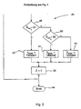
- the setpoint filter (20) in the procedural representation as shown in FIG. 3 starts with a block (30).
- a subsequent branch block (31) is first checks whether the time derivative (w ⁇ ) of the Setpoint signal (w) has positive values, d. H. it it is checked whether the setpoint signal (w) increases in time. If this is not the case, then it becomes one in the following explained in more detail allocation block (34) branches. Otherwise, it will be from the branch block (31) branches to the branching block (32).
- the branch block (32) it is checked whether the setpoint signal (w) has values which would lead to pressure values in the relay valve device (4) which lie within the response dead zone of this relay valve device. This is to be expected for values of the setpoint signal (w) below a response value (w H ) to be determined by tests. Therefore, in the presence of values of the setpoint signal (w) below the threshold value (w H ) to the assignment block (33) is branched, in which the modified setpoint signal (w ') is set to the threshold value (w H ).
- a branch is made to the allocation block (34).
- the process section then ends with a block (35).
- FIG. 4 is the Ventilpulstaktmaschineung (25) as a further part of the procedure in the form of a two sections divided flow chart shown.
- the process section begins in FIG. 4 with a Block (40).
- the variables used in this section of the procedure serve as counters (Z) and as the maximum permissible end value (Z END ) for the counter (Z).
- the end value (Z END ) thus represents the minimum waiting time, after which a subsequent drive pulse can be output to the valve devices (2, 3) at the earliest on a drive pulse.
- the end value (Z END ) can be set to different values (cycle time 1, cycle time 2, cycle time 3 ) depending on the filtered differentiated setpoint signal (w ⁇ Gef ).
- a brake operation is present (w ' ⁇ 0), then branched to a branch block (43) as shown in FIG.
- the branch block (43) it is checked whether in a past period, a sudden decrease or increase of the setpoint signal has occurred.
- the already mentioned time counters (t SAV , t SEV ) are used, which are then checked to see whether their value is smaller than the threshold value (t S ) also mentioned above. If this is the case, ie if shortly before a sudden change in the setpoint signal (w) has occurred, then the allocation block (44) is branched, in which the counter (Z) is set to the end value (Z END ). Otherwise, in one allocation block (45) of the counter (Z) by an increment value (INC Z) is increased.
- the increment value (Z INC ) may be, for example, a unit of time of one millisecond.
- a branch block (46) is continued, in which it is checked whether the counter (Z) has reached the end value (Z END ). If this is not the case, a branch is made to the already mentioned block (54), with which the method section ends. Otherwise, the end of a minimum waiting time for the output of a new drive pulse has expired, so that in a following data transfer block (47) an enable signal for the output of a drive pulse to the three-level controller (26) is output.
- a new final value (Z END ) is defined in the blocks (48, 49, 50, 51, 52) as a function of the filtered differentiated desired value signal (w ⁇ Gef ).
- it is first checked in a branch block (48) whether the filtered differentiated desired value signal (w ⁇ Gef ) is smaller than a first threshold value (S1). If so, the final value (Z END ) in an allocation block (49) is set to a first minimum wait time (clock time 1). Otherwise, the filtered differentiated setpoint signal (w ⁇ Gef ) is compared with a second threshold (S2) greater than the first threshold (S1).
- the end value (Z END ) in an assignment block (51) is set to a second minimum waiting time (Taktzeit2). Otherwise, in an allocation block (52) the final value (Z END ) is set to a third minimum waiting time (Taktzeit3).
- the minimum waiting times (Taktzeit1, Taktzeit2, Taktzeit3) are chosen so that a reverse proportionality to the values of the filtered differentiated setpoint signal (w ⁇ Gef ) and the threshold values (S1, S2) is present.
Description
Die Erfindung betrifft eine Druckregeleinrichtung, insbesondere eine elektrisch betätigbare Bremseinrichtung für ein Fahrzeug, gemäß dem Oberbegriff des Patentanspruchs 1.The invention relates to a pressure control device, in particular an electrically actuated Braking device for a vehicle, according to the preamble of patent claim 1.
Eine als elektrisch betätigbare Bremseinrichtung ausgebildete Druckregeleinrichtung ist
aus der EP 0 547 407 B1, dort insbesondere Fig. 1, bekannt.A pressure regulating device designed as an electrically operable braking device is
from
Bei der bekannten Druckregeleinrichtung ist für eine Steuerung des Drucks in einem Bremszylinder eine Ventileinrichtung vorgesehen, die ein von einem Einlaßventil und einem Auslaßventil vorgesteuertes Relaisventil aufweist. Das Auslaßventil ist dabei als stromlos geschlossenes 2/2-Wegeventil und das Einlaßventil als stromlos geöffnetes 2/2-Wegeventil ausgebildet. Damit im Falle eines Stromausfalls weiterhin eine Bremsbetätigung möglich ist und um außerdem eine plötzliche und unerwünschte Druckluftbefüllung der Bremszylinder und damit eine Zwangsbremsung des Fahrzeuges zu vermeiden, ist dem Einlaßventil ein Umschaltventil vorgeschaltet, welches im Normalfall, d.h. bei funktionierender Stromversorgung, das Einlaßventil mit einem Druckluftvorratsbehälter verbindet und bei Stromausfall das Einlaßventil mit einem pneumatischen Bremsventil verbindet. Zusätzlich ist ein Rückschlagventil vorgesehen, welches bei Stromausfall das Einlaßventil zur Entlüftung des Bremszylinders bzw. des Relaisventils überbrückt.In the known pressure control device is for a control of the pressure in one Brake cylinder valve means provided, one of an inlet valve and a Exhaust valve pilot operated relay valve has. The exhaust valve is as normally closed 2/2-way valve and the inlet valve as normally open 2/2-way valve educated. So that in case of power failure continues to brake operation is possible and in addition to a sudden and unwanted compressed air filling the brake cylinder and thus to avoid emergency braking of the vehicle is upstream of the inlet valve is a switching valve, which normally, i. e. at working Power supply, the inlet valve connects to a compressed air reservoir and in case of power failure the inlet valve connects to a pneumatic brake valve. In addition, a check valve is provided, which in case of power failure, the inlet valve bridged to vent the brake cylinder or the relay valve.
Die bekannte Druckregeleinrichtung ist relativ aufwendig. So werden neben den für die eigentliche Druckregelfunktion erforderlichen Einlaß- und Auslaßventilen noch zwei weitere Ventile, nämlich das Umschaltventil und das Rückschlagventil, benötigt.The known pressure control device is relatively expensive. So are next to the for the actual pressure control function required intake and exhaust valves two more Valves, namely the switching valve and the check valve, needed.
Aus der EP 0 669 565 A2 ist eine Druckregeleinrichtung mit einem digitalen Abtastregler bekannt, die zum Einstellen von Bremsdrücken in einem Fahrzeug verwendbar ist. Der Abtastregler dient zur elektrischen Ansteuerung einer Magnetventil-Anordnung, mit welcher ein Bremszylinder aus einem Vorrat belüftbar oder mit über einen Auslass entlüftbar ist. Die Magnetventil-Anordnung besteht aus einem Einlassventil und einem Auslassventil, die direkt an den Bremszylinder angeschlossen sind.From EP 0 669 565 A2 is a pressure control device with a digital sampling controller known, which is useful for setting brake pressures in a vehicle. Of the Sensing controller is used for the electrical control of a solenoid valve arrangement with which a brake cylinder can be ventilated from a supply or vented via an outlet is. The solenoid valve assembly consists of an inlet valve and an outlet valve, which are connected directly to the brake cylinder.
Aus der EP 0 353 003 A2 ist ein elektropneumatischer Drucksteuerapparat bekannt, welcher ein Relaisventil enthält, welches über ein elektromagnetisch betätigbares Einfassventil sowie ein elektromagnetisch betätigbares Auslassventil mit Druckluft beaufschlagbar ist.From EP 0 353 003 A2 an electropneumatic pressure control apparatus is known, which contains a relay valve, which via an electromagnetically actuated inlet valve and an electromagnetically operable outlet valve can be acted upon with compressed air.
Der Erfindung liegt daher die Aufgabe zu Grunde, eine Druckregeleinrichtung, bei der ein Relaisventil zum Einsatz kommt, anzugeben, welches eine für Bremsenbetätigungen ausreichende Regelgüte aufweist.The invention is therefore based on the object, a pressure control device in which a Relay valve is used to specify which one for brake applications sufficient Has control quality.
Diese Aufgabe wird durch die im Patentanspruch 1 angegebene Erfindung gelöst. Weiterbildungen und vorteilhafte Ausgestaltungen der Erfindung sind in den Unteransprüchen angegeben.This object is achieved by the invention defined in claim 1. further developments and advantageous embodiments of the invention are in the subclaims specified.
Die Erfindung wird im folgenden unter Nennung von Vorteilen anhand eines in den Zeichnungen dargestellten Ausführungsbeispiels näher erläutert.The invention will be described below with reference to an advantage in the drawings illustrated embodiment illustrated.
Es zeigen
- Fig. 1
- eine als elektrisch betätigbare pneumatische Bremsanlage ausgebildete Druckregeleinrichtung in schematischer Darstellung und
- Fig. 2
- ein Blockschaltbild eines in der Bremsanlage gemäß Fig. 1 verwendeten digitalen Abtastreglers und
- Fig. 3,
- 4 und 5 Teile des digitalen Abtastreglers gemäß Fig. 2 als Flußdiagramme.
- Fig. 1
- a trained as an electrically actuated pneumatic brake pressure control device in a schematic representation and
- Fig. 2
- a block diagram of a used in the brake system of FIG. 1 digital sampling controller and
- 3,
- 4 and 5 parts of the digital sampling controller of FIG. 2 as flow charts.
In den Figuren werden gleiche Bezugszeichen für einander entsprechende Teile und Signale verwendet.In the figures, the same reference numerals for each other appropriate parts and signals used.
Die in der Fig. 1 dargestellte Bremsanlage weist einen Bremszylinder (5) auf, in dem ein Bremsdruck eingestellt werden soll, der möglichst schnell und genau einem Sollwertsignal (w) folgt. Der Bremszylinder (5) betätigt bei entsprechender Druckluftbeaufschlagung dann eine in der Fig. 1 nicht dargestellte Radbremse mechanisch.The brake system shown in FIG. 1 has a Brake cylinder (5), in which a brake pressure is set should be as fast as possible and exactly one Setpoint signal (w) follows. The brake cylinder (5) operated with appropriate compressed air then a wheel brake, not shown in FIG. 1 mechanically.
Der Bremszylinder (5) ist über eine Druckluftleitung mit dem Ausgangsanschluß einer Relaisventileinrichtung (4) verbunden. Die Relaisventileinrichtung (4) weist neben dem Ausgangsanschluß noch einen Vorratsanschluß, welcher mit einem Druckluftvorratsbehälter (1) verbunden ist, und einen Steueranschluß auf, der mit zwei elektromagnetisch betätigbaren 2/2-Wegeventilen (2, 3) verbunden ist. Die 2/2-Wegeventile (2, 3) können je nach Beaufschlagung durch elektrische Betätigungssignale den Steuereingang der Relaisventileinrichtung (4) wahlweise mit dem Druckluftvorratsbehälter (1) oder mit einem in der Regel mit der umgebenden Atmosphäre verbundenen Druckluftauslaß verbinden oder eine derartige Verbindung unterbrechen. Hierbei dient das Ventil (2) als Einlaßventil und das Ventil (3) als Auslaßventil. Hiermit können somit drei sinnvolle Betätigungszustände eingestellt werden, nämlich Erhöhen, Halten und Absenken des Druckes an dem Steuereingang der Relaisventileinrichtung (4).The brake cylinder (5) is via a compressed air line to the output terminal of a relay valve device (4) connected. The relay valve device (4) points next to the output terminal still a supply terminal, which is connected to a compressed air reservoir (1) is, and a control terminal, with two Electromagnetically actuated 2/2-way valves (2, 3) connected is. The 2/2-way valves (2, 3) can ever after exposure to electrical actuation signals the control input of the relay valve device (4) optionally with the compressed air storage tank (1) or with one usually associated with the surrounding atmosphere Connect compressed air outlet or such Interrupt connection. Here, the valve (2) as an inlet valve and the valve (3) as an outlet valve. This can thus three meaningful states of actuation be adjusted, namely increase, hold and lower the pressure at the control input of the relay valve device (4).
Bei dem Ventil (2) handelt es sich um ein stromlos geschlossenes Ventil, bei dem Ventil (3) handelt es sich um ein stromlos geöffnetes Ventil. Wegen der stromlos geöffneten Ausführung des Ventils (3) ist dieses Ventil im Normalfall immer einem Betätigungsstrom beaufschlagt und dadurch geschlossen. Ein Abschalten des Betätigungsstroms führt zu einem Öffnen des Ventils. Im folgenden wird daher bei dem Ventil (2) das Einschalten eines Betätigungsstroms als Ventilbetätigung-bezeichnet, und wird bei dem Ventil (3) das Ausschalten des Betätigungsstroms als Ventilbetätigung bezeichnet. Anders ausgedrückt, es wird immer das Umschalten von dem Zustand "Ventil geschlossen" in den Zustand "Ventil geöffnet" als Betätigung des jeweiligen Ventils bezeichnet.The valve (2) is a normally closed Valve, the valve (3) is around a normally open valve. Because of the de-energized open version of the valve (3) is this valve Normally always applied to an actuating current and thereby closed. A shutdown of the operating current leads to an opening of the valve. Hereinafter will therefore turn on the valve (2) an actuating current called valve actuation, and at the valve (3) turning off the Actuating current referred to as valve actuation. Different expressed, it is always the switching of the State "valve closed" in the state "valve open" referred to as actuation of the respective valve.
Die Relaisventileinrichtung (4) dient zur Weitergabe des an dem Steuereingang anliegenden Drucks an ihren Druckluftausgang, wobei durch die Verwendung einer derartigen Relaisventileinrichtung die Druckluftdurchflußmenge im Vergleich zu den 2/2-Wegeventilen (2, 3) erheblich größer ist, so daß relativ kurze Befüllungsund Entleerungszeiten des Bremszylinders (5) ermöglicht werden.The relay valve device (4) is used for passing of the pressure applied to the control input to their Compressed air outlet, whereby by the use of such Relay valve means the compressed air flow rate Compared to the 2/2-way valves (2, 3) considerably is larger, so that relatively short filling and Emptying times of the brake cylinder (5) allows become.
Die 2/2-Wegeventile (2, 3) sind üblicherweise mit einem elektronischen Steuergerät verbunden, von dem in der stark vereinfachten Darstellung gemäß Fig. 1 ein digitaler Abtastregler (6), ein Antiblockiersystem ABS (10) sowie jeweils ein einem 2/2-Wegeventil (2, 3) zugeordneter Ausgangsverstärker (7, 8) dargestellt ist. Bei den Ausgangsverstärkern (7, 8) kann es sich beispielsweise um Schalttransistoren handeln. Das Antiblockiersystem (10), welches Geschwindigkeitssignale von einer Sensoreinrichtung (11) empfängt, ist üblicherweise in das elektronische Steuergerät integriert, z.B. als Elektronik- oder Programmodul.The 2/2-way valves (2, 3) are usually with a connected electronic control unit of which in the greatly simplified representation of FIG. 1, a digital Sensing controller (6), an anti-lock braking system ABS (10) and one each a 2/2-way valve (2, 3) assigned Output amplifier (7, 8) is shown. at the output amplifiers (7, 8) may be, for example to act switching transistors. The anti-lock system (10), which velocity signals from a Sensor device (11) receives, is usually in the electronic control unit integrates, e.g. when Electronic or program module.
Der digitale Abtastregler (6), dessen Aufbau im Folgenden noch näher beschrieben werden soll, empfängt das Sollwertsignal (w) sowie ein Istwertsignal (x) und berechnet hieraus Ausgangssignale (yEV, yAV), die den Ausgangsverstärkern (7, 8) zur Betätigung der 2/2-Wegeventile (2, 3) zugeführt werden.The digital sampling controller (6), the structure of which will be described in more detail below, receives the setpoint signal (w) and an actual value signal (x) and calculates therefrom output signals (y EV , y AV ) to the output amplifiers (7, 8) Actuation of the 2/2-way valves (2, 3) are supplied.
Das Sollwertsignal (w) wird von einem Bremswertgeber (9) erzeugt und mit einem von dem Antiblockiersystem (10) erzeugten Korrektursignal derart korrigiert, daß ein Blockieren der Räder bei einer Bremsung verhindert wird. Der Bremswertgeber (9) ist mechanisch mit dem Bremspedal eines Fahrzeuges verbunden und gibt ein die Bremspedalbetätigung durch den Fahrer repräsentierendes Signal ab. Das Istwertsignal (x) wird von einem den Bremsdruck (p) in dem Bremszylinder (5) ermittelnden Drucksensor (12) erzeugt.The setpoint signal (w) is supplied by a brake value transmitter (9) and with one of the anti-lock braking system (10) corrected correction signal corrected so that prevents locking of the wheels during braking becomes. The brake value transmitter (9) is mechanically with the Brake pedal of a vehicle connected and enters the Brake pedal operation by the driver representing Signal off. The actual value signal (x) is from a Determining brake pressure (p) in the brake cylinder (5) Pressure sensor (12) generated.
Weitere, in der Praxis üblicherweise verwendete Teile der Bremsanlage, wie z.B. ein pneumatischer Redundanzpfad, sind in der Fig. 1 zur Vereinfachung nicht dargestellt. Other commonly used parts in practice the brake system, such as a pneumatic redundancy path, are not shown in Fig. 1 for simplicity.
Die als Einlaß- und Auslaßventil verwendeten 2/2-Wegeventile (2, 3) weisen eine Ansprechtotzeit auf, die sich darin äußert, daß bei sehr kurzen Betätigungen kein Druckluftstrom fließt. Die Relaisventileinrichtung (4) enthält üblicherweise einen Relaiskolben mit einer Dichtung. Infolge von Reibungseffekten zwischen der Dichtung und Gehäuseteilen der Relaisventileinrichtung (4) weist die Relaisventileinrichtung eine Hysterese bei der Übertragung des am Steueranschluß vorliegenden Druckwertes an den Druckausgang auf. Hinzu kommt ebenfalls ein Totzeitverhalten der bei den 2/2-Wegeventilen bereits erwähnten Art. Aufgrund der zuvor erwähnten, für eine Druckregelung nicht-idealen Eigenschaften der Ventile (2, 3, 4) ist ein geeigneter, die nicht-idealen Eigenschaften kompensierender Aufbau des digitalen Abtastreglers (6) notwendig, wie er im folgenden näher erläutert wird.The 2/2-way valves used as intake and exhaust valves (2, 3) have a request dead time, the expresses itself in the fact that for very short operations no compressed air flow flows. The relay valve device (4) usually contains a relay piston with a Poetry. As a result of friction effects between the Seal and housing parts of the relay valve device (4), the relay valve device has a hysteresis in the transmission of the present at the control terminal Pressure value at the pressure outlet. Add to that a dead time behavior of the 2/2-way valves already mentioned. Due to the aforementioned, for a pressure control non-ideal properties of Valves (2, 3, 4) is a suitable, the non-ideal Features compensating construction of the digital sampling controller (6) necessary, as described in more detail below is explained.
In der Fig. 2 ist der innere Aufbau des digitalen Abtastreglers (6) näher dargestellt. Das Sollwertsignal (w) wird zunächst einem als Sollwertfilter ausgebildeten Filterglied (20) zugeführt, welches ein modifiziertes Sollwertsignal (w') abgibt. Das Sollwertfilter (20) dient dazu, daß insbesondere bei sich sprunghaft änderndem Sollwertsignal (w) der digitale Abtastregler (6) derartige Ausgangssignale (yEV, yAV) erzeugt, denen die Ventileinrichtungen (2, 3, 4) folgen können. Außerdem wird eine in der Relaisventileinrichtung (4) auftretende Ansprechtotzone bei geringen Druckwerten bereits in dem Sollwertfilter (20) kompensiert, indem ein dieser Ansprechtotzone entsprechender Wertebereich des Sollwertsignals übersprungen wird. Hierbei wird in vorteilhafter Weise derjenige Wertebereich, der übersprungen wird, derart gewählt, daß hierbei eine konstruktionsbedingte Ansprechhysterese des Bremszylinders (5) nicht überschritten wird.2, the internal structure of the digital sampling controller (6) is shown in more detail. The setpoint signal (w) is first fed to a filter element (20) designed as a setpoint filter, which outputs a modified setpoint signal (w '). The setpoint filter (20) serves, in particular when the setpoint signal (w) changes suddenly, the digital sampling controller (6) generates such output signals (y EV , y AV ) which the valve devices (2, 3, 4) can follow. In addition, a response deadband occurring in the relay valve device (4) is already compensated for at low pressure values in the setpoint filter (20) by skipping a value range of the setpoint signal corresponding to this response deadband. In this case, that range of values which is skipped is advantageously selected such that a design-related response hysteresis of the brake cylinder (5) is not exceeded.
Aus dem Ausgangssignal (w') des Sollwertfilters (20) und dem Istwertsignal (x) wird sodann durch Differenzbildung eine Regelabweichung (xW) gebildet, die einem EV/AV-Regler (21) zugeführt wird. Der EV/AV-Regler (21) dient zur Bestimmung geeigneter Zeitdauern, mit denen die 2/2-Wegeventile (2, 3) pulsförmig betätigt werden sollen, um hierüber einen gewünschten Bremsdruck in dem Bremszylinder (5) einzustellen. Jede der Zeitdauern (TEV, TAV) wird unter Verwendung eines Reglers mit einem Proportionalanteil und einem Integralanteil bestimmt, wobei der Proportionalitätsfaktor (KPEV, KPAV) und die Integrationskonstante (KIEV, KIAV) durch Versuche zu ermitteln sind. Der EV/AV-Regler (21) ist somit als PI-Regler ausgebildet. Hierbei werden für die Betätigungsdauer des Einlaßventils (2) und für die Betätigungsdauer des Auslaßventils (3) jeweils eigene Integralanteile fortlaufend aus der Regelabweichung (xW) bestimmt, wobei der Integralanteil für das Einlaßventil (2) bei positiver Regelabweichung und der Integralanteil für das Auslaßventil bei negativer Regelabweichung ermittelt wird.From the output signal (w ') of the setpoint filter (20) and the actual value signal (x), a control deviation (x W ) is then formed by subtraction, which is fed to an EV / AV controller (21). The EV / AV controller (21) is used to determine suitable periods of time with which the 2/2-way valves (2, 3) are to be actuated in a pulse-like manner in order to set a desired brake pressure in the brake cylinder (5). Each of the time periods (T EV , T AV ) is determined using a controller with a proportional component and an integral component, wherein the proportionality factor (K PEV , K PAV ) and the integration constant (K IEV , K IAV ) are to be determined by experiments. The EV / AV controller (21) is thus designed as a PI controller. Here, for the operating duration of the intake valve (2) and for the duration of operation of the exhaust valve (3) each own integral parts continuously determined from the control deviation (x W ), wherein the integral component for the intake valve (2) with positive control deviation and the integral component for the exhaust valve is determined in the event of a negative control deviation.
Neben dem Proportionalanteil und dem Integralanteil weisen die Betätigungsdauern (TEV, TAV) noch jeweils einen konstanten Anteil (TANEV, TANAV) auf, mittels dem durch die Bauart der 2/2-Wegeventile bedingte Ansprechtotzeiten kompensiert werden.In addition to the proportional component and the integral component, the operating periods (T EV , T AV ) still each have a constant component (T ANEV , T ANAV ), by means of which the response of the type of 2/2-way valves are compensated.
Der EV/AV-Regler (21) erzeugt außerdem bei einer gewünschten Druckerhöhung in dem Bremszylinder (5), die von dem Nullwert des Drucks ausgeht, eine Zusatzzeit (TO), welche als weiterer Anteil der Betätigungsdauer (TEV) für das Einlaßventil (2) additiv hinzugefügt wird. Hierdurch kann eine Ansprechtotzone der Relaisventileinrichtung (4) schnell überwunden werden.The EV / AV controller (21) also generates at a desired pressure increase in the brake cylinder (5), which starts from the zero value of the pressure, an additional time (T O ), which as a further proportion of the actuation period (T EV ) for the intake valve (2) is added additively. As a result, a Ansprechtotzone the relay valve device (4) can be overcome quickly.
Die Berechnung der Integralanteile erfolgt vorzugsweise durch numerische Integration mittels eines Mikroprozessors, d.h. durch Summation der einzelnen Werte der Regelabweichung (xW).The calculation of the integral components preferably takes place by numerical integration by means of a microprocessor, ie by summation of the individual values of the control deviation (x W ).
Die Formeln für die Ermittlung der Betätigungsdauern
(TEV, TAV) lauten somit:
Die so ermittelten Betätigungsdauern (TEV, TAV) werden sodann einem Dreipunktregler (26) zugeführt. The thus determined operating periods (T EV , T AV ) are then fed to a three-point controller (26).
Das Sollwertsignal (w) wird zusätzlich noch einem Filter (22) sowie einem nachgeschalteten Differentiationsglied (23) zugeführt und hierdurch zu einem gefilterten differenzierten Sollwertsignal (w ˙Gef) umgewandelt. Dieses Signal (w ˙Gef) wird einer Einrichtung (25) zur Erzeugung eines Ventilpulstakts und dem Dreipunktregler (26) zugeführt. Ein in einem Filter (24) durch zusätzliche Filterung des gefilterten differenzierten Sollwertsignals (w ˙Gef) gewonnenes Signal (w ˙2Gef) wird zusätzlich dem Dreipunktregler (26) zugeführt.The setpoint signal (w) is additionally supplied to a filter (22) and to a downstream differentiation element (23) and thereby converted into a filtered differentiated setpoint signal (w ˙ Gef ). This signal (w ˙ Gef ) is supplied to a device (25) for generating a Ventilpulstakts and the three-point controller (26). An in a filter (24) by additional filtering of the filtered differentiated setpoint signal (w ˙ Gef ) obtained signal (w ˙ 2Gef ) is additionally fed to the three-point controller (26).
Da bei alleiniger Verwendung des Dreipunktreglers zur Erzeugung der Ansteuerimpulse für die 2/2-Wegeventile (2, 3) die Ausgabe dieser Ansteuerimpulse zu beliebigen Zeitpunkten erfolgen könnte, d.h. ohne Berücksichtigung von minimal oder maximal zulässigen Ansteuerfrequenzen, ist dem Dreipunktregler (26) die Einrichtung (25) zur Erzeugung eines Ventilpulstakts, im folgenden auch als Ventilpulstakterzeugung bezeichnet, vorgeschaltet. Die Ventilpulstakterzeugung (25) bewirkt, daß die Ansteuerfrequenz, also der Kehrwert des zeitlichen Abstandes aufeinanderfolgender Ansteuerimpulse, auf einen für die eingesetzten 2/2-Wegeventile (2, 3) optimalen Maximalwert, der vorzugsweise kleiner als die Eigenfrequenz der Ventile ist, begrenzt wird. In einer bevorzugten Ausführungsform der Erfindung wird die Zeit seit dem Beginn des zuletzt ausgegebenen Ansteuerimpulses gemessen und erst nach Ablauf einer Mindestwartezeit ein Freigabesignal für die Ausgabe des nächsten Ansteuerimpulses an den Dreipunktregler (26) abgegeben. Bevorzugte Ansteuerfrequenzen liegen im Bereich von 10 bis 20 Hertz.Because when using only the three-point controller for Generation of the drive pulses for the 2/2-way valves (2, 3) the output of these drive pulses to arbitrary Times could occur, i. without consideration of minimum or maximum permissible drive frequencies, the three - position controller (26) is the device (25) for Generation of a Ventilpulstakt, hereinafter also as Ventilpulstaktzeugung referred upstream. The Ventilpulstaktzeugung (25) causes the driving frequency, ie the reciprocal of the time interval successive drive pulses, one for the used 2/2-way valves (2, 3) optimal maximum value, preferably smaller than the natural frequency the valves is limited. In a preferred Embodiment of the invention will be the time since Start of the last issued drive pulse measured and only after a minimum waiting time has elapsed Enable signal for the output of the next drive pulse delivered to the three-point controller (26). preferred Drive frequencies are in the range of 10 to 20 hertz.
Die Mindestwartezeit wird vorzugsweise in Abhängigkeit von dem Kehrwert des Betrags des gefilterten differenzierten Sollwertsignals (w ˙Gef) festgelegt. Dies kann bei Vermeidung eines hohen Rechenaufwandes z.B. dadurch erfolgen, daß der Wertebereich des gefilterten differenzierten Sollwertsignals (w ˙Gef) in drei Bereiche eingeteilt wird und jedem dieser Bereiche eine vordefinierte, auf den jeweiligen Bereich optimierte Mindestwartezeit zugeordnet wird. Die vordefinierten Werte der Mindestwartezeit werden dabei unter Berücksichtigung der zuvor erwähnten Bestimmungsregel festgelegt.The minimum waiting time is preferably determined as a function of the reciprocal of the amount of the filtered differentiated setpoint signal (w ˙ Gef ). This can be done by avoiding a high computational effort, for example, by dividing the value range of the filtered differentiated desired value signal (w ˙ Gef ) into three ranges and assigning each of these ranges with a predefined minimum waiting time optimized for the respective range. The predefined values of the minimum waiting time are determined taking into account the aforementioned determination rule.
Der Dreipunktregler (26) erzeugt in Abhängigkeit seiner Eingangssignale Betätigungssignale (yEV, yAV) für die 2/2-Wegeventile (2, 3). Hierbei sind die bei einem Dreipunktregler systembedingt vorhandenen Totzonen, d.h. diejenigen positiven und negativen Wertebereiche des Eingangssignals, innerhalb deren keine Ventilansteuerung erfolgt, in Abhängigkeit vom zeitlichen Solldruckgradienten veränderbar.The three-position controller (26) generates in response to its input signals actuation signals (y EV , y AV ) for the 2/2-way valves (2, 3). In this case, the dead zones which are present in the system for a three-position controller, ie those positive and negative value ranges of the input signal within which no valve control takes place, can be changed as a function of the desired pressure gradient over time.
In dem Dreipunktregler (26) werden folgende Zustände
bezüglich des gefilterten differenzierten Sollwertsignals
(w ˙Gef), das mit dem Solldruckgradienten vergleichbar
ist, unterschieden:
Des weiteren werden, wie bei einem Dreipunktregler üblich, drei verschiedene Ausgangszustände bzw. Ausgangssignale unterschieden, nämlich:
- Betätigung des Einlaßventils (2),
- Betätigung des Auslaßventils (3),
- keine Ventilbetätigung.
- Actuation of the inlet valve (2),
- Actuation of the exhaust valve (3),
- no valve actuation.
Eine Betätigung des Einlaßventils (2) erfolgt üblicherweise in der Druckaufbauphase, mit anderen Worten also dann, wenn die als Eingangsgröße für den Dreipunktregler verwendete, aus der Regelabweichung (xW) abgeleitete Regelgröße einen Schwellenwert überschreitet, d.h. eine Reglertotzone in Richtung positiver Werte verläßt. Der Schwellenwert stellt somit die Grenze einer Reglertotzone dar.An actuation of the inlet valve (2) is usually carried out in the pressure build-up phase, in other words, when the control variable derived from the control deviation (x W ) used as the input variable for the three-step controller exceeds a threshold value, ie leaves a regulator dead zone in the direction of positive values. The threshold thus represents the limit of a regulator deadband.
Bei der vorliegenden Erfindung erfolgt eine Betätigung des Einlaßventils (2) unter bestimmten Voraussetzungen jedoch auch in der Druckhaltephase oder sogar in der Druckabbauphase. Hierbei wird einerseits der Schwellenwert, mit dem die aus der Regelabweichung (xW) abgeleitete Regelgröße verglichen wird, variiert, und andererseits eine zusätzliche Bedingung abgefragt, die Auskunft darüber gibt, ob sich das Sollwertsignal (w) kurz zuvor sprunghaft geändert hat.In the present invention, however, an actuation of the inlet valve (2) under certain conditions, but also in the pressure maintenance phase or even in the pressure reduction phase. In this case, on the one hand, the threshold value with which the control variable derived from the control deviation (x W ) is compared is varied, and on the other hand an additional condition is queried which provides information as to whether the setpoint signal (w) has changed abruptly shortly before.
In Analogie hierzu wird das Auslaßventil in erster Linie, wie bei einem Dreipunktregler allgemein üblich, in der Druckabbauphase betätigt, wenn die aus der Regelabweichung (xW) abgeleitete Regelgröße einen anderen Schwellenwert in Richtung negativer Werte unterschreitet. Das Auslaßventil (3) kann aber ebenfalls bei Vorliegen bestimmter Voraussetzungen auch in der Druckhaltephase oder sogar in der Druckaufbauphase betätigt werden. Zusätzliche Voraussetzungen hierfür sind wiederum ein entsprechend angepaßter Schwellenwert sowie eine Information über in der Vergangenheit aufgetretene sprunghafte Änderungen des Sollwertsignals (w).By analogy with this, the outlet valve is primarily actuated in the pressure reduction phase, as is generally the case with a three-position controller, if the controlled variable derived from the control deviation (x W ) falls below a different threshold value in the direction of negative values. However, the outlet valve (3) can also be operated in the presence of certain conditions in the pressure maintenance phase or even in the pressure build-up phase. Additional prerequisites for this are, in turn, a correspondingly adapted threshold value as well as information about sudden changes in the setpoint signal (w) which have occurred in the past.
Bei der Auswertung sprunghafter Änderungen des Sollwertsignals (w) wird für das Einlaßventil (2) die Zeit betrachtet, die seit der letzten sprunghaften Verringerung des Sollwertsignals (w) vergangen ist, während für das Auslaßventil (3) die Zeit seit dem letzten sprunghaften Anstieg des Sollwertsignals (w) betrachtet wird.When evaluating sudden changes in the setpoint signal (w) becomes the time for the intake valve (2) considered that since the last erratic reduction of the setpoint signal (w) has passed while for the exhaust valve (3) the time since the last jump Increase of the setpoint signal (w) is considered.
Das Betätigen des Auslaßventils (3) in der Druckaufbauphase bzw. des Einlaßventils (2) in der Druckabbauphase bezeichnet man auch als Gegenregeln. Das Gegenregeln dient der Verringerung von Überschwingtendenzen bei sich schnell änderndem Druck. Da das Gegenregeln eine Druckänderung entgegengesetzt zu der durch das Sollwertsignal (w) vorgegebenen Änderung bewirkt, also eine in der Regel geringfügige Druckverringerung in der Druckaufbauphase und eine in der Regel geringfügige Druckerhöhung in der Druckabbauphase, wird im folgenden noch unterschieden zwischen dem eigentlichen Druckaufbau und dem Gegenregeln in der Druckaufbauphase bzw. dem eigentlichen Druckabbau und dem Gegenregeln in der Druckabbauphase.Actuation of the outlet valve (3) in the pressure build-up phase or the intake valve (2) in the pressure reduction phase one also designates as counter-rules. The countermeasures serves to reduce overshooting tendencies with rapidly changing pressure. Because the counter-rules a pressure change opposite to that through the setpoint signal (w) causes the predetermined change, So a usually minor pressure reduction in the pressurization phase and a generally minor one Pressure increase in the pressure reduction phase, will be in the following still different between the actual Pressure build-up and countermeasures in the pressure build-up phase or the actual pressure reduction and countermeasures in the pressure reduction phase.
Im folgenden werden die Bedingungen für die Betätigung des Einlaßventils (2) und des Auslaßventils (3) im einzelnen dargelegt, wobei folgende zusätzliche Größen verwendet werden:
- tSAV
- Zeitzähler zur Bestimmung der Zeit seit der letzten sprunghaften Verringerung des Sollwertsignals (w),
- tSEV
- Zeitzähler zur Bestimmung der Zeit seit der letzten sprunghaften Erhöhung des Sollwertsignals (w),
- ts
- Schwellenwert für Zeitzähler,
- xW1EVA
- Basisschwellenwert für eine Betätigung des Einlaßventils (2) in der Druckhaltephase kurz (tSAV < ts) nach einer sprunghaften Verringerung des Sollwertsignals (w),
- xW1EVB
- Basisschwellenwert für eine Betätigung des Einlaßventils (2) in der Druckhaltephase längere Zeit (tSAV ≥ ts) nach einer sprunghaften Verringerung des Sollwertsignals (w),
- xW1AVA
- Basisschwellenwert für eine Betätigung des Auslaßventils (3) in der Druckhaltephase kurz nach einer sprunghaften Erhöhung des Sollwertsignals (w),
- xW1AVB
- Basisschwellenwert für eine Betätigung des Auslaßventils (3) in der Druckhaltephase längere Zeit nach einer sprunghaften Erhöhung des Sollwertsignals (w),
- xW2EV
- Basisschwellenwert für eine Betätigung des Einlaßventils (2) in der Druckaufbauphase,
- xW2AV
- Basisschwellenwert für eine Betätigung des Auslaßventils (3) beim Gegenregeln in der Druckaufbauphase,
- xW3EV
- Basisschwellenwert für eine Betätigung des Einlaßventils (2) beim Gegenregeln in der Druckabbauphase,
- xW3AV
- Basisschwellenwert für eine Betätigung des Auslaßventils (3) in der Druckabbauphase.
- t SAV
- Time counter for determining the time since the last abrupt decrease of the setpoint signal (w),
- t SEV
- Time counter for determining the time since the last abrupt increase of the setpoint signal (w),
- t s
- Threshold for time counter,
- x W1EVA
- Basic threshold for actuation of the inlet valve (2) in the pressure maintenance phase shortly (t SAV <t s ) after a sudden decrease in the setpoint signal (w),
- x W1EVB
- Basic threshold for actuation of the inlet valve (2) in the pressure maintenance phase for a longer time (t SAV ≥ t s ) after a sudden decrease in the setpoint signal (w),
- x W1AVA
- Basic threshold value for an actuation of the outlet valve (3) in the pressure holding phase shortly after a sudden increase of the setpoint signal (w),
- x W1AVB
- Basic threshold value for an actuation of the outlet valve (3) in the pressure maintenance phase for a longer time after a sudden increase of the setpoint signal (w),
- x W2EV
- Basic threshold for actuation of the inlet valve (2) in the pressure build-up phase,
- x W2AV
- Basic threshold for actuation of the outlet valve (3) during counter-regulation in the pressure build-up phase,
- x W3EV
- Basic threshold value for an actuation of the inlet valve (2) during counter-regulation in the pressure reduction phase,
- x W3AV
- Basic threshold for actuation of the exhaust valve (3) in the pressure reduction phase.
Die Betätigung des Einlaßventils (2) erfolgt dann beim
Vorliegen einer oder mehrerer der folgenden Bedingungen:
Die Betätigung des Auslaßventils (3) erfolgt dagegen
beim Vorliegen einer oder mehrerer der folgenden Bedingungen:
Durch die Faktoren (k1, k2, k3) ist eine an den jeweiligen Betriebszustand des Reglers angepaßte Verschiebung der wirksamen Schwellenwerte bzw. eine Veränderung der Totzone in Abhängigkeit von den durch Differentiation und Filterung bestimmten Signalen (w ˙Gef, w ˙2Gef) des Sollwertsignals (w) möglich. Durch geeignete Dimensionierung des Faktors (k1) kann ein unerwünschtes Gegenregeln in Abhängigkeit von der Größe einer sprunghaften Änderung des Sollwertsignals (w) verhindert werden.By the factors (k 1, k 2, k 3) is adapted to the respective operating state of the controller displacement of the effective thresholds or changing the dead zone in response to the determined by differentiating and filtering signals (w ˙ Found, w ˙ 2Gef ) of the setpoint signal (w) possible. By suitable dimensioning of the factor (k 1 ), an undesired counter-regulation as a function of the magnitude of an abrupt change of the setpoint signal (w) can be prevented.
Durch geeignete Anpassung des Faktors (k2) kann der mittlere Regelungsfehler, der sich z.B. aus Einschwingvorgängen ergibt, verringert werden, da die durch diesen Faktor (k2) beeinflußte Totzone des Reglers derart verschoben wird, daß eine Betätigung des jeweiligen Ventils auch bei kleineren Regelabweichungen möglich wird und somit eine Regelung gemäß der zuvor beschriebenen PI-Charakteristik eingeleitet wird. Zusätzlich kann bei relativ kleinen sprunghaften Änderungen des Sollwertsignals (w), die beispielsweise einer Bremsdruckänderung von 0,25 bar entsprechen, ein schnelleres und zusätzlich längeres Ansprechen des Reglers erreicht werden. Hierdurch kann die Regelung sehr schnell und empfindlich auch auf kleine Änderungen des Sollwertsignals (w) reagieren.By suitable adaptation of the factor (k 2 ), the average control error resulting, for example, from transients, can be reduced because the affected by this factor (k 2 ) dead zone of the controller is shifted so that an actuation of the respective valve even at smaller Control deviations is possible and thus a control is initiated in accordance with the PI characteristic described above. In addition, with relatively small jumpy changes of the setpoint signal (w), which correspond for example to a brake pressure change of 0.25 bar, a faster and additionally longer response of the controller can be achieved. As a result, the control can respond very quickly and sensitively to small changes in the setpoint signal (w).
Mittels einer geeigneten Wahl des Faktors (k3) kann ein unerwünschtes Gegenregeln, insbesondere bei schnellen Änderungen des Sollwertsignals (w) vermieden werden. Hierdurch kann ein Hin- und Herpendeln des Reglers zwischen den Zuständen Bremsdruckaufbau und Bremsdruckabbau zuverlässig verhindert werden.By means of a suitable choice of the factor (k 3 ), an undesirable counter-regulation, in particular with rapid changes of the setpoint signal (w), can be avoided. As a result, a reciprocating of the controller between the states of brake pressure build-up and brake pressure reduction can be reliably prevented.
Im folgenden wird die Funktionsweise des Sollwertfilters (20) und der Ventilpulstakterzeugung (25) nach Art von Verfahrensschritten anhand von Flußdiagrammen näher erläutert. Das Sollwertfilter (20) und die Ventilpulstakterzeugung (25) könnten somit als Teile eines Steuerprogramms für einen Mikroprozessor praktisch realisiert werden. Es wäre auch möglich, sie durch entsprechende elektronische Schaltungsanordnungen praktisch zu realisieren. The following is the operation of the setpoint filter (20) and the valve pulse clock generation (25) according to Art of process steps based on flow charts closer explained. The setpoint filter (20) and the valve pulse clock generation (25) could thus be considered parts of a Control program for a microprocessor practically realized become. It would also be possible by appropriate electronic circuitry practical to realize.
Das Sollwertfilter (20) in der verfahrensmäßigen Darstellung gemäß Fig. 3 beginnt mit einem Block (30). In einem nachfolgenden Verzweigungsblock (31) wird zunächst überprüft, ob die zeitliche Ableitung (w ˙) des Sollwertsignals (w) positive Werte aufweist, d. h. es wird geprüft, ob das Sollwertsignal (w) zeitlich ansteigt. Wenn dies nicht der Fall ist, so wird zu einem im folgenden noch näher erläuterten Zuweisungsblock (34) verzweigt. Anderenfalls wird von dem Verzweigungsblock (31) zu dem Verzweigungsblock (32) verzweigt.The setpoint filter (20) in the procedural representation as shown in FIG. 3 starts with a block (30). In a subsequent branch block (31) is first checks whether the time derivative (w ˙) of the Setpoint signal (w) has positive values, d. H. it it is checked whether the setpoint signal (w) increases in time. If this is not the case, then it becomes one in the following explained in more detail allocation block (34) branches. Otherwise, it will be from the branch block (31) branches to the branching block (32).
In dem Verzweigungsblock (32) wird überprüft, ob das Sollwertsignal (w) Werte aufweist, die zu Druckwerten in der Relaisventileinrichtung (4) führen würden, die innerhalb der Ansprechtotzone dieser Relaisventileinrichtung liegen. Dies ist bei Werten des Sollwertsignals (w) unterhalb eines durch Versuche zu ermittelnden Ansprechwertes (wH) zu erwarten. Daher wird bei Vorliegen von Werten des Sollwertsignals (w) unterhalb des Ansprechwertes (wH) zu dem Zuweisungsblock (33) verzweigt, in welchem das modifizierte Sollwertsignal (w') auf den Ansprechwert (wH) gesetzt wird.In the branch block (32) it is checked whether the setpoint signal (w) has values which would lead to pressure values in the relay valve device (4) which lie within the response dead zone of this relay valve device. This is to be expected for values of the setpoint signal (w) below a response value (w H ) to be determined by tests. Therefore, in the presence of values of the setpoint signal (w) below the threshold value (w H ) to the assignment block (33) is branched, in which the modified setpoint signal (w ') is set to the threshold value (w H ).
Falls die Überprüfung in dem Verzweigungsblock (32) negativ
ausfällt, so wird zu dem Zuweisungsblock (34)
verzweigt. In dem Zuweisungsblock (34) wird mittels numerischer
Tiefpaßfilterung erster Ordnung ein neuer
Wert für das modifizierte Sollwertsignal (w') aus einem
alten, zuvor berechneten Wert des modifizierten Sollwertsignals
(w') und aus dem Sollwertsignal selbst nach
folgender Formel berechnet:
Die Größe (kW) stellt eine Filterkonstante dar. Ein bevorzugter
Wert ist kW = 0.25.
Daraufhin endet der Verfahrensabschnitt mit einem Block
(35).The quantity (k W ) represents a filter constant. A preferred value is k W = 0.25.
The process section then ends with a block (35).
In den Fig. 4 und 5 ist die Ventilpulstakterzeugung (25) als weiterer Verfahrensabschnitt in Form eines in zwei Abschnitte unterteilten Flußdiagramms dargestellt. Der Verfahrensabschnitt beginnt in der Fig. 4 mit einem Block (40).In Figs. 4 and 5 is the Ventilpulstaktzeugung (25) as a further part of the procedure in the form of a two sections divided flow chart shown. The process section begins in FIG. 4 with a Block (40).
Die in diesem Verfahrensabschnitt verwendeten Variablen
(Z, ZENDE) dienen als Zähler (Z) und als höchstzulässiger
Endwert (ZENDE) für den Zähler (Z). Der Endwert
(ZENDE) stellt damit die Mindestwartezeit dar, nach der
auf einen Ansteuerimpuls frühestens ein darauffolgender
Ansteuerimpuls an die Ventileinrichtungen (2, 3) ausgegeben
werden kann. Der Endwert (ZENDE) kann dabei in Abhängigkeit
von dem gefilterten differenzierten Sollwertsignal
(w ˙Gef) auf verschiedene Werte (Taktzeitl,
Taktzeit2, Taktzeit3) gesetzt werden.The variables used in this section of the procedure (Z, Z END ) serve as counters (Z) and as the maximum permissible end value (Z END ) for the counter (Z). The end value (Z END ) thus represents the minimum waiting time, after which a subsequent drive pulse can be output to the valve devices (2, 3) at the earliest on a drive pulse. The end value (Z END ) can be set to different values (cycle time 1,
In einem darauffolgenden Verzweigungsblock (41) wird zunächst überprüft, ob eine Bremsbetätigung vorliegt (w' # 0) oder nicht (w' = 0). Wenn keine Bremsbetätigung vorliegt, so wird zu einem Zuweisungsblock (42) verzweigt, indem der Zähler (Z) und der Endwert (ZENDE) auf für den Beginn einer Abbremsung sinnvolle Anfangswerte (Z:=Taktzeit3-ZINC, ZENDE:=Taktzeit3) gesetzt werden. Die Größe (ZINC) ist ein weiter unter erläuterter Inkrement-Wert. Die Anfangswerte sind dabei so gewählt, daß zu Beginn einer Bremsbetätigung sofort ein Freigabesignal zur Erzeugung eines Ansteuerimpulses für die Ventileinrichtung (2, 3) erzeugt werden kann. Sodann wird dieser Verfahrensabschnitt mit dem Block (54) in Fig. 5 beendet.In a subsequent branching block (41), it is first checked whether there is a braking operation (w '# 0) or not (w' = 0). If there is no brake operation, an assignment block (42) is branched, in which the counter (Z) and the end value (Z END ) are set to initial values which are meaningful for the beginning of a deceleration (Z: = cycle time 3-Z INC , Z END : = cycle time 3 ). The size (Z INC ) is further below explained increment value. The initial values are chosen so that at the beginning of a brake operation immediately a release signal for generating a drive pulse for the valve device (2, 3) can be generated. Then, this process section is terminated with the block (54) in FIG. 5.
Wenn eine Bremsbetätigung vorliegt (w' ≠ 0), dann wird gemäß Fig. 4 zu einem Verzweigungsblock (43) verzweigt. In dem Verzweigungsblock (43) wird überprüft, ob in einem vergangenen Zeitraum eine sprunghafte Verringerung oder Erhöhung des Sollwertsignals aufgetreten ist. Hierfür werden die bereits erwähnten Zeitzähler (tSAV, tSEV) verwendet, die daraufhin überprüft werden, ob ihr Wert kleiner als der ebenfalls bereits erwähnte Schwellenwert (tS) ist. Wenn dies der Fall ist, d. h. wenn kurz zuvor eine sprunghafte Veränderung des Sollwertsignals (w) aufgetreten ist, dann wird zu dem Zuweisungsblock (44) verzweigt, in welchem der Zähler (Z) auf den Endwert (ZENDE) gesetzt wird. Anderenfalls wird in einem Zuweisungsblock (45) der Zähler (Z) um einen Inkrement-Wert (ZINC) erhöht. Der Inkrement-Wert (ZINC) kann beispielsweise eine Zeiteinheit von einer Millisekunde sein.If a brake operation is present (w '≠ 0), then branched to a branch block (43) as shown in FIG. In the branch block (43) it is checked whether in a past period, a sudden decrease or increase of the setpoint signal has occurred. For this purpose, the already mentioned time counters (t SAV , t SEV ) are used, which are then checked to see whether their value is smaller than the threshold value (t S ) also mentioned above. If this is the case, ie if shortly before a sudden change in the setpoint signal (w) has occurred, then the allocation block (44) is branched, in which the counter (Z) is set to the end value (Z END ). Otherwise, in one allocation block (45) of the counter (Z) by an increment value (INC Z) is increased. The increment value (Z INC ) may be, for example, a unit of time of one millisecond.
Sodann wird mit einem Verzweigungsblock (46) fortgefahren, in dem überprüft wird, ob der Zähler (Z) den Endwert (ZENDE) erreicht hat. Wenn dies nicht der Fall ist, so wird zu dem bereits erwähnten Block (54) verzweigt, mit dem der Verfahrensabschnitt endet. Anderenfalls ist das Ende einer Mindestwartezeit für die Ausgabe eines neuen Ansteuerimpulses abgelaufen, so daß in einem folgenden Datentransferblock (47) ein Freigabesignal für die Ausgabe eines Ansteuerimpulses an den Dreipunktregler (26) ausgegeben wird.Then, a branch block (46) is continued, in which it is checked whether the counter (Z) has reached the end value (Z END ). If this is not the case, a branch is made to the already mentioned block (54), with which the method section ends. Otherwise, the end of a minimum waiting time for the output of a new drive pulse has expired, so that in a following data transfer block (47) an enable signal for the output of a drive pulse to the three-level controller (26) is output.
Hiernach wird gemäß Fig. 5 in den Blöcken (48, 49, 50, 51, 52) in Abhängigkeit von dem gefilterten differenzierten Sollwertsignal (w ˙Gef) ein neuer Endwert (ZENDE) festgelegt. Hierbei wird in einem Verzweigungsblock (48) zunächst überprüft, ob das gefilterte differenzierte Sollwertsignal (w ˙Gef) kleiner ist als ein erster Schwellenwert (S1). Wenn dies der Fall ist, so wird der Endwert (ZENDE) in einem Zuweisungsblock (49) auf eine erste Mindestwartezeit (Taktzeit1) gesetzt. Anderenfalls wird das gefilterte differenzierte Sollwertsignal (w ˙Gef) mit einem zweiten Schwellenwert (S2), der größer ist als der erste Schwellenwert (S1), verglichen. Bei Unterschreitung des zweiten Schwellenwertes (S2) wird der Endwert (ZENDE) in einem Zuweisungsblock (51) auf eine zweite Mindestwartezeit (Taktzeit2) gesetzt. Anderenfalls wird in einem Zuweisungsblock (52) der Endwert (ZENDE) auf eine dritte Mindestwartezeit (Taktzeit3) gesetzt.Thereafter, according to FIG. 5, a new final value (Z END ) is defined in the blocks (48, 49, 50, 51, 52) as a function of the filtered differentiated desired value signal (w ˙ Gef ). In this case, it is first checked in a branch block (48) whether the filtered differentiated desired value signal (w ˙ Gef ) is smaller than a first threshold value (S1). If so, the final value (Z END ) in an allocation block (49) is set to a first minimum wait time (clock time 1). Otherwise, the filtered differentiated setpoint signal (w ˙ Gef ) is compared with a second threshold (S2) greater than the first threshold (S1). If the second threshold value (S2) is undershot, the end value (Z END ) in an assignment block (51) is set to a second minimum waiting time (Taktzeit2). Otherwise, in an allocation block (52) the final value (Z END ) is set to a third minimum waiting time (Taktzeit3).
In vorteilhafter Weise sind die Mindestwartezeiten
(Taktzeit1, Taktzeit2, Taktzeit3) so gewählt, daß eine
umgekehrte Proportionalität zu den Werten des gefilterten
differenzierten Sollwertsignals (w ˙Gef) bzw. den
Schwellenwerten (S1, S2) vorliegt. Dies bedeutet, daß
die erste Mindestwartezeit (Taktzeit1) größer ist als
die anderen Mindestwartezeiten (Taktzeit2, Taktzeit3)
und die zweite Mindestwartezeit (Taktzeit2) größer ist
als die dritte Mindestwartezeit (Taktzeit3).Advantageously, the minimum waiting times (Taktzeit1, Taktzeit2, Taktzeit3) are chosen so that a reverse proportionality to the values of the filtered differentiated setpoint signal (w ˙ Gef ) and the threshold values (S1, S2) is present. This means that the first minimum wait time (clock time 1) is greater than the other minimum wait times (
Schließlich wird in einem Zuweisungsblock (53) der Zähler (Z) auf einen Anfangswert (0) zurückgesetzt. Daraufhin endet der Verfahrensabschnitt mit dem Block (54).Finally, in an allocation block (53), the counter (Z) reset to an initial value (0). thereupon the procedure section ends with the block (54).
Claims (6)
- Pressure control device, especially an electrically actuatable braking device for a vehicle, having a valve device (2, 3) for increasing, reducing or maintaining a pressure (p) in a load (5), comprising a 2/2-way valve acting as inlet valve (2) and a 2/2-way valve, which is open when unenergised, acting as outlet valve (3), a relay valve device (4) being arranged between the valve device (2, 3) and the load (5), characterised in that , for minimising a control error (xw) which can occur between an actual value signal (x) derived from the pressure (p) and a desired value signal (w), the valve device (2, 3) is arranged to be acted upon by actuation signals, there being provided for generating the actuation signals for the valve device (2, 3) a digital sampling controller (6) comprising a series connection of a filter element (20), a PI controller (21) and a three-position controller (26).
- Pressure control device according to one of the preceding claims, characterised in that the valve device (2, 3) is arranged to be acted upon by a time-modulated digital signal the switching frequency of which is below the natural frequency of the valve device (2, 3).
- Pressure control device according to one of the preceding claims, characterised in that the desired value signal (w) is derived from the output signal of a braking value generator (9) which emits an electrical signal representing the actuation of a brake pedal.
- Pressure control device according to one of the preceding claims, characterised in that the digital sampling controller (6) comprises a device (25) for generating valve clocking pulses, connected upstream of the three-position controller (26).
- Pressure control device according to one of the preceding claims, characterised in that the digital sampling controller (6) comprises a series connection of a low pass (22), a differentiation element (23) and a further low pass (24).
- Pressure control device according to one of the preceding claims, characterised in that the three-position controller (26) has variable dead zones which are arranged to be modified in dependence upon abrupt changes in the desired value signal (w) that have occurred in the past.
Applications Claiming Priority (2)
| Application Number | Priority Date | Filing Date | Title |
|---|---|---|---|
| DE19905684A DE19905684A1 (en) | 1999-02-11 | 1999-02-11 | Pressure control device |
| DE19905684 | 1999-02-11 |
Publications (3)
| Publication Number | Publication Date |
|---|---|
| EP1028043A2 EP1028043A2 (en) | 2000-08-16 |
| EP1028043A3 EP1028043A3 (en) | 2003-04-02 |
| EP1028043B1 true EP1028043B1 (en) | 2005-03-09 |
Family
ID=7897162
Family Applications (1)
| Application Number | Title | Priority Date | Filing Date |
|---|---|---|---|
| EP99124169A Expired - Lifetime EP1028043B1 (en) | 1999-02-11 | 1999-12-03 | Pressure control device |
Country Status (2)
| Country | Link |
|---|---|
| EP (1) | EP1028043B1 (en) |
| DE (2) | DE19905684A1 (en) |
Cited By (1)
| Publication number | Priority date | Publication date | Assignee | Title |
|---|---|---|---|---|
| DE102015001628A1 (en) | 2015-02-07 | 2016-08-11 | Wabco Gmbh | Method for setting brake pressures of a motor vehicle via control of a pressure control valve, brake system for carrying out the method and motor vehicle |
Families Citing this family (3)
| Publication number | Priority date | Publication date | Assignee | Title |
|---|---|---|---|---|
| DE102009059811B3 (en) * | 2009-12-21 | 2011-09-01 | Knorr-Bremse Systeme für Nutzfahrzeuge GmbH | Multi-channel pressure control module with only one pressure sensor |
| JP5838875B2 (en) * | 2012-03-16 | 2016-01-06 | トヨタ自動車株式会社 | Hydraulic control device and hydraulic brake system |
| CN103287418B (en) * | 2013-07-01 | 2017-09-22 | 王石麟 | Automobile automatic emergency complemental brake system |
Family Cites Families (17)
| Publication number | Priority date | Publication date | Assignee | Title |
|---|---|---|---|---|
| DE2811345C2 (en) * | 1978-03-16 | 1986-12-11 | Knorr-Bremse AG, 8000 München | Pressure regulators for pneumatic pressures, in particular in vehicles |
| DE3138647A1 (en) * | 1981-09-29 | 1983-04-14 | Dr.Ing.H.C. F. Porsche Ag, 7000 Stuttgart | "CONTROL DEVICE FOR SOLENOID VALVES" |
| DE3240277A1 (en) * | 1982-10-30 | 1984-05-03 | Robert Bosch Gmbh, 7000 Stuttgart | Pressure medium brake system |
| DE3543145C2 (en) * | 1985-12-06 | 1995-08-03 | Bosch Gmbh Robert | Electric braking system for a vehicle |
| DE3636140C2 (en) * | 1986-10-24 | 1997-03-20 | Knorr Bremse Ag | Pressure regulator |
| GB8817796D0 (en) * | 1988-07-26 | 1988-09-01 | Bendix Ltd | Fluid pressure control relay valve device & apparatus |
| DE3927110A1 (en) * | 1989-08-17 | 1991-02-21 | Bosch Gmbh Robert | SOLENOID VALVE WITH EXCITING CURRENT CONTROL DEVICE |
| DE4004502A1 (en) * | 1990-02-14 | 1991-08-22 | Daimler Benz Ag | ELECTRONICALLY CONTROLLED PRESSURE BRAKE DEVICE |
| DE4029793C2 (en) * | 1990-09-20 | 1999-05-06 | Bosch Gmbh Robert | Hydraulic vehicle brake system |
| DE4031551C1 (en) * | 1990-10-05 | 1992-01-30 | Mercedes-Benz Aktiengesellschaft, 7000 Stuttgart, De | Braking installation with electronically-regulated pressure medium - keeps 3-2 way valve in working position during slip-regulated braking process by electromagnet valve |
| GB9102472D0 (en) * | 1991-02-05 | 1991-03-20 | Lucas Ind Plc | Braking system for a vehicle |
| DE4141995A1 (en) | 1991-12-19 | 1993-06-24 | Bosch Gmbh Robert | COMPRESSED AIR BRAKE SYSTEM, ESPECIALLY FOR COMMERCIAL VEHICLES |
| JPH0736551A (en) * | 1993-07-20 | 1995-02-07 | Smc Corp | Pressure controller for electro-pneumatic regulator |
| DE4406235A1 (en) * | 1994-02-25 | 1995-08-31 | Wabco Vermoegensverwaltung | Pressure control device |
| DE4428929A1 (en) * | 1994-08-16 | 1996-02-22 | Wabco Gmbh | Method and device for pressure control |
| DE19548207A1 (en) * | 1995-12-22 | 1997-06-26 | Bosch Gmbh Robert | Hydraulic vehicle brake system with at least one electrically controllable valve |
| DE19654427B4 (en) * | 1996-12-24 | 2009-08-13 | Robert Bosch Gmbh | Method and device for regulating the pressure in at least one wheel brake |
-
1999
- 1999-02-11 DE DE19905684A patent/DE19905684A1/en not_active Withdrawn
- 1999-12-03 EP EP99124169A patent/EP1028043B1/en not_active Expired - Lifetime
- 1999-12-03 DE DE59911727T patent/DE59911727D1/en not_active Expired - Lifetime
Cited By (2)
| Publication number | Priority date | Publication date | Assignee | Title |
|---|---|---|---|---|
| DE102015001628A1 (en) | 2015-02-07 | 2016-08-11 | Wabco Gmbh | Method for setting brake pressures of a motor vehicle via control of a pressure control valve, brake system for carrying out the method and motor vehicle |
| US11198421B2 (en) | 2015-02-07 | 2021-12-14 | Zf Cv Systems Europe Bv | Method for adjusting brake pressures of a vehicle via control of a pressure control valve, brake system for carrying out the method and motor vehicle |
Also Published As
| Publication number | Publication date |
|---|---|
| EP1028043A2 (en) | 2000-08-16 |
| EP1028043A3 (en) | 2003-04-02 |
| DE59911727D1 (en) | 2005-04-14 |
| DE19905684A1 (en) | 2000-08-17 |
Similar Documents
| Publication | Publication Date | Title |
|---|---|---|
| EP0669565B1 (en) | Pressure control device | |
| DE2811345C2 (en) | Pressure regulators for pneumatic pressures, in particular in vehicles | |
| EP2152555B1 (en) | Correction method for the correction of characteristic curves for analogized hydraulic valves in motor vehicle braking systems | |
| EP0697317B1 (en) | Method and device for pressure control | |
| EP2387523B1 (en) | Method for operating a hydraulic or pneumatic system | |
| EP1625058B1 (en) | Method for learning characteristic curves for hydraulic valves | |
| EP0381957B1 (en) | Antilock braking system with limited yawing moment | |
| EP0840684B1 (en) | Method and device for activating a solenoid valve | |
| WO2018007187A1 (en) | Device and method for actuating valves | |
| EP3537244A1 (en) | Regulation and/or control method for an electro-pneumatic field device | |
| DE19848960B4 (en) | Method and device for controlling a pressure control valve, in particular a brake system | |
| EP1808348B1 (en) | Locking arms and exact pressure regulation with control valves for regulating brake pressure in rail vehicles | |
| EP1028043B1 (en) | Pressure control device | |
| EP0473914B1 (en) | Control system for an actuator in an internal combustion engine | |
| DE4214547A1 (en) | VEHICLE BRAKING SYSTEM | |
| EP3724046B1 (en) | Braking system having a correction device for correcting an opening time of a valve and method for correcting the opening time of the valve | |
| DE19727945B4 (en) | Method and device for the controlled control of a proportionally operated solenoid valve | |
| DE2908871A1 (en) | VEHICLE BRAKING SYSTEM | |
| DE10200771B4 (en) | Method for controlling the brake pressure with proportional valves | |
| DE3636139C2 (en) | Brake cylinder pressure regulator for air brakes of vehicles | |
| DE102009051514A1 (en) | Control device i.e. microcontroller, for controlling pressure of volume of gas stream i.e. compressed air, has combination device providing actual actuating variable to actuating unit to adjust initial-pressure to pre-set reference-pressure | |
| DE10062978A1 (en) | Method and device for controlling the brake system of a vehicle | |
| WO2002061517A1 (en) | Regulating device and method for regulating the dynamic behaviour of a wheel | |
| EP1117578B1 (en) | Device for controlling the braking power of a brake system | |
| DE102007059116A1 (en) | Hydraulic pressure regulating method for high pressure accumulator of internal-combustion engine, involves forming prediction signal based on correcting variable of control unit and information about real temporal characteristic of pressure |
Legal Events
| Date | Code | Title | Description |
|---|---|---|---|
| PUAI | Public reference made under article 153(3) epc to a published international application that has entered the european phase |
Free format text: ORIGINAL CODE: 0009012 |
|
| AK | Designated contracting states |
Kind code of ref document: A2 Designated state(s): AT BE CH CY DE DK ES FI FR GB GR IE IT LI LU MC NL PT SE |
|
| AX | Request for extension of the european patent |
Free format text: AL;LT;LV;MK;RO;SI |
|
| PUAL | Search report despatched |
Free format text: ORIGINAL CODE: 0009013 |
|
| AK | Designated contracting states |
Kind code of ref document: A3 Designated state(s): AT BE CH CY DE DK ES FI FR GB GR IE IT LI LU MC NL PT SE |
|
| AX | Request for extension of the european patent |
Extension state: AL LT LV MK RO SI |
|
| 17P | Request for examination filed |
Effective date: 20031002 |
|
| 17Q | First examination report despatched |
Effective date: 20031124 |
|
| AKX | Designation fees paid |
Designated state(s): DE FR SE |
|
| GRAP | Despatch of communication of intention to grant a patent |
Free format text: ORIGINAL CODE: EPIDOSNIGR1 |
|
| GRAS | Grant fee paid |
Free format text: ORIGINAL CODE: EPIDOSNIGR3 |
|
| GRAA | (expected) grant |
Free format text: ORIGINAL CODE: 0009210 |
|
| AK | Designated contracting states |
Kind code of ref document: B1 Designated state(s): DE FR SE |
|
| REG | Reference to a national code |
Ref country code: SE Ref legal event code: TRGR |
|
| REG | Reference to a national code |
Ref country code: IE Ref legal event code: FG4D Free format text: GERMAN |
|
| REF | Corresponds to: |
Ref document number: 59911727 Country of ref document: DE Date of ref document: 20050414 Kind code of ref document: P |
|
| PLBE | No opposition filed within time limit |
Free format text: ORIGINAL CODE: 0009261 |
|
| STAA | Information on the status of an ep patent application or granted ep patent |
Free format text: STATUS: NO OPPOSITION FILED WITHIN TIME LIMIT |
|
| ET | Fr: translation filed | ||
| 26N | No opposition filed |
Effective date: 20051212 |
|
| REG | Reference to a national code |
Ref country code: FR Ref legal event code: PLFP Year of fee payment: 17 |
|
| REG | Reference to a national code |
Ref country code: FR Ref legal event code: PLFP Year of fee payment: 18 |
|
| REG | Reference to a national code |
Ref country code: FR Ref legal event code: PLFP Year of fee payment: 19 |
|
| PGFP | Annual fee paid to national office [announced via postgrant information from national office to epo] |
Ref country code: SE Payment date: 20181219 Year of fee payment: 20 |
|
| PGFP | Annual fee paid to national office [announced via postgrant information from national office to epo] |
Ref country code: FR Payment date: 20181218 Year of fee payment: 20 |
|
| PGFP | Annual fee paid to national office [announced via postgrant information from national office to epo] |
Ref country code: DE Payment date: 20181231 Year of fee payment: 20 |
|
| REG | Reference to a national code |
Ref country code: DE Ref legal event code: R071 Ref document number: 59911727 Country of ref document: DE |
|
| REG | Reference to a national code |
Ref country code: SE Ref legal event code: EUG |