EP1490735B1 - Method and controller for the adaptive control of at least one component of a technical plant - Google Patents
Method and controller for the adaptive control of at least one component of a technical plant Download PDFInfo
- Publication number
- EP1490735B1 EP1490735B1 EP03711843A EP03711843A EP1490735B1 EP 1490735 B1 EP1490735 B1 EP 1490735B1 EP 03711843 A EP03711843 A EP 03711843A EP 03711843 A EP03711843 A EP 03711843A EP 1490735 B1 EP1490735 B1 EP 1490735B1
- Authority
- EP
- European Patent Office
- Prior art keywords
- actual value
- controller
- value
- time
- component
- Prior art date
- Legal status (The legal status is an assumption and is not a legal conclusion. Google has not performed a legal analysis and makes no representation as to the accuracy of the status listed.)
- Expired - Lifetime
Links
- 238000000034 method Methods 0.000 title claims abstract description 34
- 230000003044 adaptive effect Effects 0.000 title description 2
- 230000008859 change Effects 0.000 claims description 49
- 230000002123 temporal effect Effects 0.000 claims description 12
- 230000004044 response Effects 0.000 claims description 8
- 230000003321 amplification Effects 0.000 abstract description 30
- 238000003199 nucleic acid amplification method Methods 0.000 abstract description 30
- 230000001105 regulatory effect Effects 0.000 abstract description 6
- 230000008569 process Effects 0.000 description 14
- 230000010355 oscillation Effects 0.000 description 12
- 230000006870 function Effects 0.000 description 6
- 230000006978 adaptation Effects 0.000 description 5
- 230000001276 controlling effect Effects 0.000 description 5
- 230000008901 benefit Effects 0.000 description 3
- 238000009434 installation Methods 0.000 description 2
- 238000013178 mathematical model Methods 0.000 description 2
- 230000009467 reduction Effects 0.000 description 2
- 230000009471 action Effects 0.000 description 1
- 230000032683 aging Effects 0.000 description 1
- 230000015556 catabolic process Effects 0.000 description 1
- 238000006243 chemical reaction Methods 0.000 description 1
- 238000006731 degradation reaction Methods 0.000 description 1
- 230000008021 deposition Effects 0.000 description 1
- 230000000694 effects Effects 0.000 description 1
- 231100001261 hazardous Toxicity 0.000 description 1
- 230000003993 interaction Effects 0.000 description 1
- 238000011835 investigation Methods 0.000 description 1
- 238000004519 manufacturing process Methods 0.000 description 1
- 238000010327 methods by industry Methods 0.000 description 1
- 230000007363 regulatory process Effects 0.000 description 1
- 230000008439 repair process Effects 0.000 description 1
- 230000026676 system process Effects 0.000 description 1
Images

Classifications
-
- G—PHYSICS
- G05—CONTROLLING; REGULATING
- G05B—CONTROL OR REGULATING SYSTEMS IN GENERAL; FUNCTIONAL ELEMENTS OF SUCH SYSTEMS; MONITORING OR TESTING ARRANGEMENTS FOR SUCH SYSTEMS OR ELEMENTS
- G05B11/00—Automatic controllers
- G05B11/01—Automatic controllers electric
- G05B11/36—Automatic controllers electric with provision for obtaining particular characteristics, e.g. proportional, integral, differential
- G05B11/42—Automatic controllers electric with provision for obtaining particular characteristics, e.g. proportional, integral, differential for obtaining a characteristic which is both proportional and time-dependent, e.g. P.I., P.I.D.
-
- G—PHYSICS
- G05—CONTROLLING; REGULATING
- G05B—CONTROL OR REGULATING SYSTEMS IN GENERAL; FUNCTIONAL ELEMENTS OF SUCH SYSTEMS; MONITORING OR TESTING ARRANGEMENTS FOR SUCH SYSTEMS OR ELEMENTS
- G05B13/00—Adaptive control systems, i.e. systems automatically adjusting themselves to have a performance which is optimum according to some preassigned criterion
- G05B13/02—Adaptive control systems, i.e. systems automatically adjusting themselves to have a performance which is optimum according to some preassigned criterion electric
- G05B13/0205—Adaptive control systems, i.e. systems automatically adjusting themselves to have a performance which is optimum according to some preassigned criterion electric not using a model or a simulator of the controlled system
- G05B13/024—Adaptive control systems, i.e. systems automatically adjusting themselves to have a performance which is optimum according to some preassigned criterion electric not using a model or a simulator of the controlled system in which a parameter or coefficient is automatically adjusted to optimise the performance
Definitions
- the invention relates to a method for controlling at least one component of a technical system and a corresponding controller.
- Starting point is a conventional control concept, according to which a controlled variable of a component of the technical system should be kept as well as possible on a setpoint of the controlled variable by means of a PI controller.
- the PI controller determines from the difference of the setpoint and the actual value of the controlled variable (control deviation) a control action on an actuator associated with the component, so that the controlled variable reaches the desired setpoint as quickly and accurately as possible and on the other hand in the course of the control as little as possible away from this setpoint.
- the actual value of the controlled variable has too strong a vibration, so that the control system, consisting of the component of the technical system and the controller possibly tends to instabilities.
- control parameters of a PI controller used for control in particular the gain factor and the reset time, in advance to a constant value and not to change during the control process during operation of the system.
- This has the advantage that when using a PI controller only a few parameters must be set, in particular the previously mentioned controller parameters, and that during the control process often no further settings must be made.
- the use of once preset parameter values for the PI controller is especially in the control of power plants is not always optimal because over time, during operation of the power plant, the dynamic behavior of a realized by the component of the technical system process engineering process can change.
- the controller parameters once set in advance after such a change in the dynamic behavior of the component for the new operating case now no longer optimal and may even lead to a failure of the scheme, so that a once desired control success is no longer achievable.
- the actual value of the controlled variable tends to produce unwanted oscillations during the control process, which leads to instability of the controlled system can.
- a set of parameter values for the PI controller which can be regarded as optimal for an operating state of the component to be controlled, can at least provide only conditionally usable control results for another operating case of this component as a result of the existing nonlinearities. Shifts so the operating point of a regulated, non-linear component of the technical system during operation of the technical system - which inevitably occurs - so once set controller parameters for the now existing, new operating point (operating point) of the component may not be suitable to to achieve a desired control result. This may even lead to a PI controller showing optimum control behavior for one component operating point, but providing completely inadequate or even hazardous control results when moving to a new operating point.
- the document US 3,798,426 shows a system for controlling processes, wherein an adaptive controller is used whose proportional component can be adjusted.
- the reset time of the integral component is specified.
- the proportional is changed until the actual value of the controlled process variable is within a tolerance band which is defined by the definition of a limit value lying above the setpoint value or a limit value lying below the setpoint value.
- the invention is therefore based on the object to provide an improved method and a controller for controlling at least one component of a technical system.
- described disadvantages of the prior art should be overcome.
- a control method according to the invention and a controller according to the invention are intended to reduce the outlay for setting the controller parameters.
- a method according to the invention as well as a controller according to the invention should enable a particularly simple startup of a component to be controlled.
- the invention is based on the consideration that the controller parameters can be set particularly well when the behavior of the controlled path, so the interaction of the PI controller and the component to be controlled, is observed during operation of the technical system and according to the Behavior of the actual value of the controlled variable of the gain of the PI controller during operation of the technical system is automatically changed until the actual value of the controlled variable is in said tolerance band with respect to the predetermined setpoint and remains therein. Changes in the amplification factor are therefore not carried out continuously, but only until the actual value of the controlled variable with respect to the tolerance band shows a desired behavior, ie moves within the tolerance band during the operation of the technical system.
- the amplification factor in carrying out the invention Method only changed again when the actual value of the controlled variable is in terms of value removed from the tolerance band. This renewed change in the amplification factor happens again only until the actual value dips back into the tolerance band and remains there.
- the inventive method a method for automatically adapting the gain of the PI controller is realized, wherein during operation of the technical system depending on the behavior of the actual value of the controlled variable, the gain is automatically changed until it leads to a desired control behavior of the controlled component , A renewed change of the amplification factor takes place only if the actual value of the controlled variable is removed from the tolerance band by value.
- the continuous change of the amplification factor can be effected for example by means of a stepwise change of the current value of the amplification factor by a defined amount.
- the controller parameter readjustment time is determined in advance in the method according to the invention, that is not continuously changed during operation of the technical system.
- the reset time is determined from time constants, in particular from the sum of the time constants, of the component to be controlled.
- the path time constants of a path to be controlled have an influence on the speed with which the path responds to a change in at least one of its input signals with a change in at least one of its output signals.
- Almost every practically existing controlled system is subject to a so-called delay, thus comprising in its corresponding mathematical model equation at least one path time constant.
- a controlled system which can be described by a mathematical model equation of the third order, comprises three path time constants.
- the sum of the time constants of the route to be regulated is formed and the readjustment time is determined by means of this sum and in particular set as a multiple of this sum.
- this multiple moves in the range between 0.1 and 2.5.
- the amplification factor in step 4 of the method according to the invention is lowered if the time profile of the actual value is less than a first predetermined time period during which the actual value has a value within the tolerance band.
- oscillations in the temporal behavior of the actual value are to be recognized, which in particular show that the actual value during the control process assumes a value within the tolerance band, but leaves the tolerance band again and only later on again in the tolerance band and again exit.
- the dwell time during which the oscillating actual value moves within the tolerance band is then determined, before it leaves the tolerance band again. The shorter this dwell time, the faster the actual value changes over time, so that in such a case, the gain of the PI controller is to be reduced in order to leave the actual value in the tolerance band during operation of the technical system.
- the dwell time is less than the first predetermined period, it is assumed that the actual value is over-oscillated (the actual value passes "too fast” through the tolerance band) and the amplification factor is reduced so that such an intolerable overshoot of the actual value beyond the limits of the tolerance band.
- the first predetermined period of time can be determined, for example, as a function of the values of the time-of-flight constants, in particular as a function of the value of the sum of the time-of-flight constants.
- the dwell time of the actual value can be set to a technically meaningful relation to the deceleration of the controlled system (described by the time constants), since an absolute definition of what is a too strong oscillation can not be specified. For example, a change in temperature within a few minutes may indicate a rapid process, whereas a change in pressure usually marks a rather sluggish process within a few minutes.
- step 4 the amplification factor is only lowered if, in addition, a first rate of change of the actual value is greater than a second rate of change of the nominal value.
- the desired value not only a constant size, but also a variable, in particular fluctuating and / or oscillating size may include.
- a variable in particular fluctuating and / or oscillating size
- Such changing values of the setpoint during the control process as well as an incorrectly set value of the amplification factor would lead to fluctuations and / or oscillations of the actual value of the controlled variable.
- fluctuations and / or oscillations of the actual value are even desired in the case of a likewise fluctuating and / or oscillating value of the corresponding nominal value, since the actual value of the controlled variable should follow the nominal value of the controlled variable during the regulating process as well as possible.
- the gain factor is to decrease, since in this case, the fluctuations of the actual value are not caused solely by a fluctuating setpoint, but by a gain set too high in value.
- the amplification factor is increased in step 4 of the method according to the invention, if the time course of the actual value has a rise time, which includes the period from the beginning of a change of the setpoint until reaching a current value of the actual value within the tolerance band which is greater than a second predetermined period.
- the gain is increased when the response of the controlled system to a change in the setpoint is too slow.
- the said rise time of the actual value is determined, which corresponds to the period between a change of the setpoint and a first reaching of a value within the tolerance band by the actual value.
- the rise time is thus a measure of how quickly the actual value of the controlled system responds to a change in the setpoint value, in particular to a sudden change, and reaches a (desired) value within the tolerance band with respect to the setpoint value.
- the second predetermined period serves as a criterion when the rise time of the actual value is too large, ie the response of the controlled system to a change in the desired value is therefore to be regarded as too slow.
- this second predetermined period is determined from the time constants of the component to be controlled, in particular from the sum of the time constants.
- the rise time is set in relation to the delay of the controlled system, so that a definition of what is to be regarded as too slow reaction of the controlled system, can be set in a meaningful technical context with the delay of the controlled system.
- the reset time is determined by time constants, in particular the sum of the time constants, of the component to be controlled.
- the amplification factor is reduced by means of the adaptation unit if the time profile of the actual value is a dwell time, while the actual value assumes a value within the tolerance band that is less than a first predetermined period of time.
- the amplification factor is reduced by means of the adaptation unit only if, in addition, a first rate of change of the actual value is greater than a second rate of change of the nominal value.
- the amplification factor is increased by means of the adaptation unit, if the time profile of the actual value has a rise time, which includes the period from the beginning of a change of the setpoint until reaching a current value of the actual value within the tolerance band, which is greater is as a second predetermined period.
- the time profile of an actual value I is shown as an example, which has a vibration and does not approach a given setpoint value S well enough over a relatively long period of time, ie in particular does not move within a tolerance band Tb.
- FIG 1 The illustration of FIG 1 is intended to show the temporal behavior of the setpoint and actual value of a controlled component of a technical system.
- the tolerance band Tb is to be adapted to the respective specific area of application and should reflect an admissible deviation of the actual value I from the desired setpoint value S during the control process.
- the limits of the tolerance band Tb need not be symmetrical with respect to the setpoint S; they can rather be adapted to the requirements of a specific application.
- the gain Kp is to be lowered. This is particularly indicated because a dwell time T11 is less than a first predetermined time period T1. This can be interpreted as meaning that the actual value I "passes too fast" through the tolerance band Tb during its time course, which indicates an unwanted oscillation of the actual value I.
- the comparison period (first predetermined period T1) is advantageously determined by means of the time constant of the component to be controlled, so that the fact that the previously mentioned term "too fast" should be defined relative to the system-related delay of the component to be controlled can be taken into account.
- the current reduction of the gain Kp is terminated as soon as the time course of the actual value moves in the tolerance band Tb and remains in this.
- the reduction of the amplification factor Kp can be carried out by multiplication by a constant value between 0 and 1, namely whenever the current actual value has passed through the tolerance band.
- the actual value I which should follow the temporal course of the desired value S as well as possible, also exhibits oscillating behavior.
- the amplification factor Kp should only be lowered if the actual value I changes faster than the setpoint S.
- the change ⁇ S of the setpoint value S during the reference period ⁇ t and the change ⁇ I of the actual value I are shown by way of example with reference to a reference period ⁇ t.
- the quotient of .DELTA.S and .DELTA.t or .DELTA.I and .DELTA.t allows a determination of the aforementioned rates of change of actual value I and setpoint S.
- the rate of change of the actual value I (first rate of change) is smaller than that Rate of change of setpoint S (second rate of change). It can therefore be concluded that the oscillations of the actual value I are due to oscillations of the setpoint S, so that in the present case, the gain Kp of the PI controller used is not to be lowered.
- characteristic values are shown in the example of FIG. 3, namely a rise time T22 and a second predefined time period T2.
- the rise time T22 comprises the period from the beginning of a change of the setpoint value S until a current value of the actual value I within the tolerance band is reached. If this rise time T22 is greater than the second predetermined time period T2, then the component controlled by a PI controller responds to a setpoint change too slow and the gain Kp is to increase.
- the second predetermined time period T2 is determined from the time constants of the component to be controlled, so that technically correct depending on the system-related delay of the component to be controlled (controlled system) It can be judged whether the rise time T22 of the actual value I is too large and therefore the amplification factor Kp is to be increased.
- FIG. 4 shows a regulator R. according to the invention.
- the controller R is used to control at least one component of a technical system and is designed as a PI controller.
- the controller R comprises a gain factor Kp and a reset time Tn as controller parameters.
- a first controller input E1 can be acted upon by a predetermined reset time Tn.
- the regulator R also has an adaptation unit A, by means of which the actual value I of the controlled variable can be determined during the operation of the technical system and the amplification factor Kp can be varied as a function of the time behavior of the actual value I until the actual value I of the controlled variable is within a tolerance band Tb the setpoint S remains.
- the input E2 is supplied with an initial value Kp0 for the amplification factor Kp.
- This initial value Kp0 is then continuously varied during the control process as a function of the time behavior of the actual value until the actual value I of the controlled variable remains within a tolerance band Tb with respect to the desired value S.
- the controller R further comprises a controller output Y, which a Command value provides, by means of which the component to be controlled is controlled in order to achieve a desired behavior of the actual value I.
- controller input (E1, E2, E3) are not to be construed restrictively to the effect that in a controller according to the invention a physical connection must be present, to which the variables mentioned are to be applied.
- controller input should encompass all means by means of which the PI controller can be supplied with the mentioned variables.
- controller input is intended to encompass all circuit possibilities of the operational amplifier by means of electronic components which, in their interconnection, realize a specific value for at least one of the variables Tn and Kp.
- controller input should encompass all memory areas into which values for the controller parameters Tn and Kp are written and / or from which these values are read out.
Abstract
Description
Die Erfindung betrifft ein Verfahren zur Regelung mindestens einer Komponente einer technischen Anlage sowie einen entsprechenden Regler.The invention relates to a method for controlling at least one component of a technical system and a corresponding controller.
Ausgangspunkt ist dabei ein konventionelles Regelungskonzept, wonach eine Regelgröße einer Komponente der technischen Anlage mittels eines PI-Reglers möglichst gut auf einem Sollwert der Regelgröße gehalten werden soll. Der PI-Regler ermittelt dabei aus der Differenz des Sollwerts und des Istwerts der Regelgröße (Regelabweichung) einen Stelleingriff auf einen der Komponente zugeordneten Aktor, so dass die Regelgröße den gewünschten Sollwert zum einen möglichst schnell und genau erreicht und zum anderen sich im Verlauf der Regelung möglichst wenig von diesem Sollwert entfernt. Insbesondere soll verhindert werden, dass der Istwert der Regelgröße eine zu starke Schwingung aufweist, so dass das Regelsystem bestehend aus der Komponente der technischen Anlage und dem Regler womöglich zu Instabilitäten neigt.Starting point is a conventional control concept, according to which a controlled variable of a component of the technical system should be kept as well as possible on a setpoint of the controlled variable by means of a PI controller. The PI controller determines from the difference of the setpoint and the actual value of the controlled variable (control deviation) a control action on an actuator associated with the component, so that the controlled variable reaches the desired setpoint as quickly and accurately as possible and on the other hand in the course of the control as little as possible away from this setpoint. In particular, it should be prevented that the actual value of the controlled variable has too strong a vibration, so that the control system, consisting of the component of the technical system and the controller possibly tends to instabilities.
Bei der Regelung von Kraftwerkskomponenten ist es beispielsweise bekannt, Regelparameter eines zur Regelung eingesetzten PI-Reglers, insbesondere den Verstärkungsfaktor und die Nachstellzeit, jeweils vorab auf einen konstanten Wert einzustellen und während des Regelvorgangs beim Betrieb der Anlage nicht mehr zu verändern. Dies hat den Vorteil, dass bei der Verwendung eines PI-Reglers nur wenige Parameter eingestellt werden müssen, insbesondere die vorher genannten Reglerparameter, und dass während des Regelvorgangs oftmals keine weiteren Einstellungen mehr vorgenommen werden müssen.In the control of power plant components, it is known, for example, to set control parameters of a PI controller used for control, in particular the gain factor and the reset time, in advance to a constant value and not to change during the control process during operation of the system. This has the advantage that when using a PI controller only a few parameters must be set, in particular the previously mentioned controller parameters, and that during the control process often no further settings must be made.
Jedoch ist die Verwendung von einmal vorab eingestellten Parameterwerten für den PI-Regler insbesondere bei der Regelung von Kraftwerksanlagen nicht immer optimal, da sich im Laufe der Zeit während des Betriebs der Kraftwerksanlage das dynamische Verhalten eines durch die Komponente der technischen Anlage verwirklichten verfahrenstechnischen Prozesses verändern kann. Somit sind die einmal vorab eingestellten Reglerparameter nach einer derartigen Veränderung des dynamischen Verhaltens der Komponente für den nun vorliegenden neuen Betriebsfall nicht mehr optimal und führen u.U. sogar zu einem Versagen der Regelung, so dass ein einmal gewünschter Regelerfolg nicht mehr erzielbar ist. Beispielsweise kann es nach einer Änderung des dynamischen Verhaltens der Regelstrecke (Komponente) und somit des durch die Komponente und den PI-Regler gebildeten Regelkreises dazu führen, dass der Istwert der Regelgröße beim Regelvorgang zu unerwünschten Schwingungen neigt, was zu einer Instabilität der geregelten Strecke führen kann. Um eine derartige Regelung wieder für den Einsatz während des Betriebs der technischen Anlage zu ertüchtigen, ist es meist notwendig, zumindest die betreffende Komponente der technischen Anlage außer Betrieb zu nehmen, die Reglerparameter entsprechend des geänderten dynamischen Verhaltens der Regelstrecke neu einzustellen - was möglicherweise Umfangreiche Testläufe vor erneuter Inbetriebnahme notwendig macht - und die Komponente einschließlich ihres Reglers anschließend wieder in Betrieb zu nehmen.However, the use of once preset parameter values for the PI controller is especially in the control of power plants is not always optimal because over time, during operation of the power plant, the dynamic behavior of a realized by the component of the technical system process engineering process can change. Thus, the controller parameters once set in advance after such a change in the dynamic behavior of the component for the new operating case now no longer optimal and may even lead to a failure of the scheme, so that a once desired control success is no longer achievable. For example, after a change in the dynamic behavior of the controlled system (component) and thus of the control loop formed by the component and the PI controller, the actual value of the controlled variable tends to produce unwanted oscillations during the control process, which leads to instability of the controlled system can. In order to get such a control back for use during operation of the technical system, it is usually necessary to take at least the relevant component of the technical system out of service, to reset the controller parameters according to the changed dynamic behavior of the controlled system - possibly extensive test runs before re-commissioning - and then put the component including its controller back into operation.
Abgesehen davon, dass eine funktionsuntüchtig gewordener Regelkreis der technischen Anlage zur Gefährdung von Maschinen und menschlichem Bedienpersonal führen kann - insbesondere wenn eine instabil gewordene Regelstrecke viel zu große Stelleingriffe und/oder viel zu große Istwerte der Regelgröße erzeugt -, ist infolge der zwangsläufig erforderlichen Stillstandszeit zur Instandsetzung der Regelung ein Produktionsausfall der technischen Anlage praktisch unvermeidlich. Wenn es sich bei der technischen Anlage um eine Kraftwerksanlage handelt, so kann ein Ausfall einer Komponente der technischen Anlage beispielsweise dazu führen, die Versorgung eines Gebiets mit elektrischer Energie zu gefährden.Apart from the fact that an inoperable control loop of the technical system can endanger the machines and human operating personnel - especially when an unstable controlled system generates too large actuating interventions and / or much too large actual values of the controlled variable -, due to the inevitably required downtime for Repair of the regulation a loss of production of the technical equipment practically inevitable. For example, if the technical installation is a power plant, failure of a component of the technical installation may endanger the supply of electrical energy to an area.
Die Verwendung von konstanten Werten für den PI-Regler führt insbesondere bei der Verwendung zur Regelung in Kraftwerksanlagen mit einem Dampfprozess zu Problemen, da in einem derartigen Kraftwerk zu beherrschende Regelstrecken oftmals ein nichtlineares Verhalten aufweisen. Ein Satz von Parameterwerten für den PI-Regler, der für einen Betriebszustand der zu regelnden Komponente als optimal angesehen werden kann, kann für einen anderen Betriebsfall dieser Komponente infolge der vorhandenen Nichtlinearitäten zumindest nur bedingt brauchbare Regelergebnisse liefern. Verschiebt sich also der Arbeitspunkt einer zu regelnden, nichtlinearen Komponente der technischen Anlage während des Betriebs der technischen Anlage - was zwangsläufig vorkommt -, so sind die einmal eingestellten Reglerparameter für den nun vorliegenden, neuen Betriebspunkt (Arbeitspunkt) der Komponente womöglich nicht mehr geeignet, um einen gewünschten Regelerfolg herbeizuführen. Dies kann sogar so weit führen, dass ein PI-Regler für einen Betriebspunkt der Komponente ein optimales Regelverhalten zeigt, aber beim Übergang auf einen neuen Betriebspunkt völlig unzureichende oder sogar gefährdende Regelergebnisse liefert.The use of constant values for the PI controller leads to problems, especially when used for control in power plants with a steam process, since in such a power plant to be controlled systems often have a non-linear behavior. A set of parameter values for the PI controller, which can be regarded as optimal for an operating state of the component to be controlled, can at least provide only conditionally usable control results for another operating case of this component as a result of the existing nonlinearities. Shifts so the operating point of a regulated, non-linear component of the technical system during operation of the technical system - which inevitably occurs - so once set controller parameters for the now existing, new operating point (operating point) of the component may not be suitable to to achieve a desired control result. This may even lead to a PI controller showing optimum control behavior for one component operating point, but providing completely inadequate or even hazardous control results when moving to a new operating point.
Die Druckschrift US 3,798,426 zeigt ein System zur Regelung von Prozessen, wobei ein adaptiver Regler verwendet wird, dessen Proportionalanteil angepasst werden kann. Die Nachstellzeit des Integralanteils ist vorgegeben. Nach einer Änderung des Stellwertes wird der Proportional solange verändert, bis sich der Istwert der geregelten Prozessgröße innerhalb eines Toleranzbandes befindet, das durch die Definition eines oberhalb des Sollwertes liegenden Grenzwertes bzw. eines unterhalb des Sollwertes liegenden Grenzwertes gegeben ist.The document US 3,798,426 shows a system for controlling processes, wherein an adaptive controller is used whose proportional component can be adjusted. The reset time of the integral component is specified. After a change in the manipulated variable, the proportional is changed until the actual value of the controlled process variable is within a tolerance band which is defined by the definition of a limit value lying above the setpoint value or a limit value lying below the setpoint value.
Der Erfindung liegt daher die Aufgabe zugrunde, ein verbessertes Verfahren sowie einen Regler zur Regelung mindestens einer Komponente einer technischen Anlage anzugeben. Dabei sollen insbesondere beschriebene Nachteile aus dem Stand der Technik überwunden werden. Ferner soll ein erfindungsgemäßes Regelverfahren sowie ein erfindungsgemäßer Regler den Aufwand für die Einstellung der Reglerparameter reduzieren. Außerdem sollen ein erfindungsgemäßes Verfahren sowie ein erfindungsgemäßer Regler eine besonders einfache Inbetriebsetzung einer zu regelnden Komponente ermöglichen.The invention is therefore based on the object to provide an improved method and a controller for controlling at least one component of a technical system. In particular, described disadvantages of the prior art should be overcome. Furthermore, a control method according to the invention and a controller according to the invention are intended to reduce the outlay for setting the controller parameters. In addition, a method according to the invention as well as a controller according to the invention should enable a particularly simple startup of a component to be controlled.
Bezüglich des Verfahrens wird die Aufgabe erfindungsgemäß gelöst durch ein Verfahren zur Regelung mindestens einer Komponente einer technischen Anlage mittels eines PI-Reglers, wel-cher als Reglerparameter einen Verstärkungsfaktor und eine Nachstellzeit umfasst, mit folgenden Schritten:
- 1. Die Nachstellzeit wird vorgegeben.
- 2. Ein Anfangswert des Verstärkungsfaktors wird vorgegeben.
- 3. Mindestens ein Sollwert einer Regelgröße der Komponente wird vorgegeben, und
- 4. während des Betriebs der technischen Anlage wird laufend der Istwert der Regelgröße bestimmt und der Verstärkungsfaktor in Abhängigkeit vom zeitlichen Verhalten des Istwerts verändert, bis der Istwert der Regelgröße innerhalb eines Toleranzbandes bezüglich des Sollwertes verbleibt.
- 1. The reset time is specified.
- 2. An initial value of the gain factor is given.
- 3. At least one setpoint of a controlled variable of the component is specified, and
- 4. During operation of the technical system, the actual value of the controlled variable is continuously determined and the amplification factor as a function of the time behavior of the actual value changed until the actual value of the controlled variable remains within a tolerance band with respect to the setpoint.
Die Erfindung geht dabei von der Überlegung aus, dass die Reglerparameter dann besonders gut festgelegt werden können, wenn das Verhalten der geregelten Strecke, also das Zusammenwirken des PI-Reglers und der zu regelnden Komponente, während des Betriebs der technischen Anlage beobachtet wird und entsprechend des Verhaltens des Istwerts der Regelgröße der Verstärkungsfaktor des PI-Reglers während des Betriebs der technischen Anlage automatisch so lange verändert wird, bis sich der Istwert der Regelgröße im genannten Toleranzband bezüglich des vorgegebenen Sollwerts befindet und darin verbleibt. Veränderungen des Verstärkungsfaktors werden also nicht laufend vorgenommen, sondern nur so lange, bis der Istwert der Regelgröße bezüglich des Toleranzbandes ein gewünschtes Verhalten zeigt, sich also während des Betriebs der technischen Anlage wertmäßig innerhalb des Toleranzbandes bewegt. Wenn nun im Verlauf des Betriebs die geregelte Komponente einer Veränderung bezüglich ihres dynamischen Verhaltens unterliegt, beispielsweise verursacht durch Materialverschleiß und/oder Ablagerung von Betriebs- oder Hilfsstoffen der Komponente, oder durch Alterung von Teilen der Komponente, so wird der Verstärkungsfaktor bei der Durchführung des erfindungsgemäßen Verfahrens erst dann wieder verändert, wenn der Istwert der Regelgröße sich wertmäßig vom Toleranzband entfernt. Diese erneute laufende Veränderung des Verstärkungsfaktors geschieht wieder nur so lange, bis der Istwert wieder ins Toleranzband eintaucht und dort verbleibt.The invention is based on the consideration that the controller parameters can be set particularly well when the behavior of the controlled path, so the interaction of the PI controller and the component to be controlled, is observed during operation of the technical system and according to the Behavior of the actual value of the controlled variable of the gain of the PI controller during operation of the technical system is automatically changed until the actual value of the controlled variable is in said tolerance band with respect to the predetermined setpoint and remains therein. Changes in the amplification factor are therefore not carried out continuously, but only until the actual value of the controlled variable with respect to the tolerance band shows a desired behavior, ie moves within the tolerance band during the operation of the technical system. If, during operation, the controlled component is subject to a change in its dynamic behavior, for example due to material wear and / or deposition of operating or auxiliary components of the component, or due to aging of parts of the component, the amplification factor in carrying out the invention Method only changed again when the actual value of the controlled variable is in terms of value removed from the tolerance band. This renewed change in the amplification factor happens again only until the actual value dips back into the tolerance band and remains there.
Durch das erfindungsgemäße Verfahren ist ein Verfahren zur automatischen Adaption des Verstärkungsfaktors des PI-Reglers realisiert, wobei während des Betriebs der technischen Anlage abhängig vom Verhalten des Istwerts der Regelgröße der Verstärkungsfaktor automatisch so lange verändert wird, bis er zu einem gewünschten Regelverhalten der geregelten Komponente führt. Eine erneute Veränderung des Verstärkungsfaktors erfolgt nur, wenn sich der Istwert der Regelgröße wieder Wertmäßig vom Toleranzband entfernt. Die laufende Veränderung des Verstärkungsfaktors kann beispielsweise mittels einer schrittweisen Veränderung des aktuellen Werts des Verstärkungsfaktors um einen festgelegten Betrag erfolgen.The inventive method, a method for automatically adapting the gain of the PI controller is realized, wherein during operation of the technical system depending on the behavior of the actual value of the controlled variable, the gain is automatically changed until it leads to a desired control behavior of the controlled component , A renewed change of the amplification factor takes place only if the actual value of the controlled variable is removed from the tolerance band by value. The continuous change of the amplification factor can be effected for example by means of a stepwise change of the current value of the amplification factor by a defined amount.
Der Reglerparameter Nachstellzeit wird beim erfindungsgemäßen Verfahren vorab festgelegt, während des Betriebs der technischen Anlage also nicht laufend verändert.The controller parameter readjustment time is determined in advance in the method according to the invention, that is not continuously changed during operation of the technical system.
Untersuchungen von geregelten Strecken haben gezeigt, dass ein Vorab-Einstellen des Reglerparameters Nachstellzeit meist ausreichend ist, um ein gutes, gewünschtes Regelverhalten der geregelten Stecke zu erzielen. Es ist also nicht erforderlich, zur Erzielung eines guten Regelergebnisses während des Betriebs der technischen Anlage auch den Reglerparameter Nachstellzeit laufend zu verändern. Dies hat u.a. den Vorteil, dass die Dynamik der geregelten Strecke, z.B. für weitergehende Untersuchungen oder Testzwecke, leichter beschreib- und modellierbar ist, da sich das dynamische Verhalten des PI-Reglers infolge der einmal vorab festgelegten Nachstellzeit nicht verändert und eine entsprechende beispielsweise mathematische Beschreibung der geregelten Strecke einfach angebbar und handhabbar ist.Investigations of controlled paths have shown that a pre-adjustment of the controller parameter readjustment time is usually sufficient to achieve a good, desired control behavior of the controlled plug. It is therefore not necessary to constantly change the controller parameter reset time to achieve a good control result during operation of the technical system. This has the advantage, inter alia, that the dynamics of the controlled path, eg for further examinations or test purposes, can be described and modeled more easily, since the dynamic behavior of the PI controller does not change as a result of the once predefined reset time and a corresponding mathematical description, for example the regulated route is easy to set and handle.
Vorteilhaft wird die Nachstellzeit aus Streckenzeitkonstanten, insbesondere aus der Summe der Streckenzeitkonstanten, der zu regelnden Komponente bestimmt.Advantageously, the reset time is determined from time constants, in particular from the sum of the time constants, of the component to be controlled.
Die Streckenzeitkonstanten einer zu regelnden Strecke haben Einfluss auf die Geschwindigkeit, mit welcher die Strecke auf eine Änderung mindestens eines ihrer Eingangssignale mit einer Änderung mindestens eines ihrer Ausgangssignale reagiert. Nahezu jede praktisch vorkommende Regelstrecke ist mit einer sogenannten Verzögerung behaftet, umfasst in ihrer korrespondierenden mathematischen Modellgleichung also mindestens eine Streckenzeitkonstante. Beispielsweise umfasst eine Regelstrecke, welche durch eine mathematische Modellgleichung dritter Ordnung beschrieben werden kann, drei Streckenzeitkonstanten. Eine Kenntnis der Werte der Streckenzeitkonstanten für eine betrachtete Regelstrecke ermöglicht eine gute Abschätzung der Verzögerung der Regelstrecke.The path time constants of a path to be controlled have an influence on the speed with which the path responds to a change in at least one of its input signals with a change in at least one of its output signals. Almost every practically existing controlled system is subject to a so-called delay, thus comprising in its corresponding mathematical model equation at least one path time constant. For example, a controlled system, which can be described by a mathematical model equation of the third order, comprises three path time constants. A knowledge of the values of the time constants for a considered controlled system allows a good estimation of the delay of the controlled system.
Besonders vorteilhaft ist es, wenn die Summe der Streckenzeitkonstanten der zu regelnden Strecke gebildet wird und die Nachstellzeit mittels dieser Summe bestimmt und insbesondere als ein Vielfaches dieser Summe eingestellt wird. Vorteilhaft bewegt sich dieses Vielfache im Bereich zwischen 0,1 und 2,5.It is particularly advantageous if the sum of the time constants of the route to be regulated is formed and the readjustment time is determined by means of this sum and in particular set as a multiple of this sum. Advantageously, this multiple moves in the range between 0.1 and 2.5.
In vielen praktisch vorkommenden Fällen haben Versuche gezeigt, dass ein Vielfaches mit einem Wert von etwa 1,5 zu guten Ergebnissen führt, dass also die Nachstellzeit des PI-Reglers in diesen Fällen vorteilhaft auf einen Wert einzustellen ist, der dem Eineinhalbfachen der Summe der Streckenzeitkonstanten entspricht. Des Weiteren haben Vielfache mit einem Wert von etwa 0,7 ebenfalls zu guten Ergebnissen geführt, dass also die Nachstellzeit des PI-Reglers in derartigen Fällen vorteilhaft auf einen Wert einzustellen ist, der 70 % der Summe der Streckenzeitkonstanten entspricht. Dabei ist jedoch zu beachten, dass mit steigendem Wert für das genannte Vielfache der I-Anteil des PI-Reglers immer weniger wirkt.In many practical cases, tests have shown that a multiple of a value of about 1.5 leads to good results, so that the reset time of the PI controller in these cases is advantageously set to a value which is one and a half times the sum of the line time constants equivalent. Furthermore, multiples with a value of approximately 0.7 have likewise led to good results, that is to say that the reset time of the PI controller in such cases is advantageously set to a value which corresponds to 70% of the sum of the time constants. It should be noted, however, that as the value for said multiple increases, the I component of the PI controller becomes less and less effective.
In einer weiteren vorteilhaften Ausgestaltung der Erfindung wird der Verstärkungsfaktor in Schritt 4 des erfindungsgemä-ßen Verfahrens erniedrigt, wenn der zeitliche Verlauf des Istwerts eine Verweil-Zeit, während welcher der Istwert einen Wert innerhalb des Toleranzbandes aufweist, kleiner ist als ein erster vorgegebener Zeitraum.In a further advantageous embodiment of the invention, the amplification factor in step 4 of the method according to the invention is lowered if the time profile of the actual value is less than a first predetermined time period during which the actual value has a value within the tolerance band.
Bei dieser Ausführungsform sollen insbesondere Schwingungen im zeitlichen Verhalten des Istwerts erkannt werden, welche sich insbesondere dadurch zeigen, dass der Istwert zwar während des Regelvorgangs einen Wert innerhalb des Toleranzbandes annimmt, das Toleranzband aber wieder verlässt und erst später wieder in das Toleranzband ein- und wieder austritt. Es wird nun die Verweil-Zeit bestimmt, während welcher sich der schwingende Istwert innerhalb des Toleranzbandes bewegt, bevor er wieder aus diesem austritt. Je kürzer diese Verweil-Zeit ist, desto schneller ändert sich der Istwert im Verlauf der Zeit, so dass in einem derartigen Fall der Verstärkungsfaktor des PI-Reglers zu verringern ist, um den Istwert während des Betriebs der technischen Anlage im Toleranzband zu belassen. Ist die Verweil-Zeit kleiner als der erste vorgegebene Zeitraum, so wird von einer zu starken Schwingung des Istwerts ausgegangen (der Istwert geht "zu schnell" durch das Toleranzband hindurch) und der Verstärkungsfaktor verringert, so dass ein derartiges, nicht tolerables Überschwingen des Istwerts über die Grenzen des Toleranzbands hinaus verhindert wird.In this embodiment, in particular oscillations in the temporal behavior of the actual value are to be recognized, which in particular show that the actual value during the control process assumes a value within the tolerance band, but leaves the tolerance band again and only later on again in the tolerance band and again exit. The dwell time during which the oscillating actual value moves within the tolerance band is then determined, before it leaves the tolerance band again. The shorter this dwell time, the faster the actual value changes over time, so that in such a case, the gain of the PI controller is to be reduced in order to leave the actual value in the tolerance band during operation of the technical system. If the dwell time is less than the first predetermined period, it is assumed that the actual value is over-oscillated (the actual value passes "too fast" through the tolerance band) and the amplification factor is reduced so that such an intolerable overshoot of the actual value beyond the limits of the tolerance band.
Der erste vorgegebene Zeitraum kann beispielsweise in Abhängigkeit von den Werten der Streckenzeitkonstanten, insbesondere in Abhängigkeit vom Wert der Summe der Streckenzeitkonstanten, bestimmt werden. So kann beim oben genannten Vergleich die Verweil-Zeit des Istwerts in eine technisch sinnvolle Relation zur Verzögerung der Regelstrecke (beschrieben durch die Streckenzeitkonstanten) gesetzt werden, da eine absolute Definition darüber, was eine zu starke Schwingung ist, nicht angegeben werden kann. Beispielsweise kann eine Temperaturänderung innerhalb weniger Minuten einen schnellen Vorgang bezeichnen, wohingegen eine Druckänderung innerhalb weniger Minuten meist einen eher trägen Vorgang charakterisiert.The first predetermined period of time can be determined, for example, as a function of the values of the time-of-flight constants, in particular as a function of the value of the sum of the time-of-flight constants. Thus, in the above-mentioned comparison, the dwell time of the actual value can be set to a technically meaningful relation to the deceleration of the controlled system (described by the time constants), since an absolute definition of what is a too strong oscillation can not be specified. For example, a change in temperature within a few minutes may indicate a rapid process, whereas a change in pressure usually marks a rather sluggish process within a few minutes.
Vorteilhaft wird in Schritt 4 der Verstärkungsfaktor nur dann erniedrigt, wenn zusätzlich eine erste Änderungsgeschwindigkeit des Istwerts größer ist als eine zweite Änderungsgeschwindigkeit des Sollwerts.Advantageously, in step 4, the amplification factor is only lowered if, in addition, a first rate of change of the actual value is greater than a second rate of change of the nominal value.
Bei dieser Ausgestaltung der.Erfindung wird dem Umstand Rechnung getragen, dass der Sollwert nicht nur eine konstante Größe, sondern auch eine veränderliche, insbesondere schwankende und/oder schwingende Größe, umfassen kann. Derart sich verändernde Werte des Sollwerts während des Regelvorgangs würden ebenso wie ein falsch eingestellter Wert des Verstärkungsfaktors zu Schwankungen und/oder Schwingungen des Istwerts der Regelgröße führen. Jedoch sind solche Schwankungen und/oder Schwingungen des Istwerts bei einem ebenfalls schwankenden und/oder schwingenden Wert des korrespondierenden Sollwerts sogar gewünscht, da der Istwert der Regelgröße dem Sollwert der Regelgröße während des Regelvorgangs möglichst gut folgen soll.In this embodiment der.Erfindung the fact is taken into account that the desired value not only a constant size, but also a variable, in particular fluctuating and / or oscillating size may include. Such changing values of the setpoint during the control process as well as an incorrectly set value of the amplification factor would lead to fluctuations and / or oscillations of the actual value of the controlled variable. However, such fluctuations and / or oscillations of the actual value are even desired in the case of a likewise fluctuating and / or oscillating value of the corresponding nominal value, since the actual value of the controlled variable should follow the nominal value of the controlled variable during the regulating process as well as possible.
Um in einem derartigen Fall ein (unerwünschtes) Erniedrigen des Verstärkungsfaktors verursacht durch einen schwankenden Istwert zu verhindern, ist es bei dieser Ausführungsform vorgesehen, eine erste Änderungsgeschwindigkeit des Istwerts sowie eine zweite Änderungsgeschwindigkeit des Sollwerts zu ermitteln, um aus dem Vergleich dieser beiden Geschwindigkeiten dann schließlich festzulegen, ob der Verstärkungsfaktor zu erniedrigen ist oder nicht.In such a case, in order to prevent (undesired) lowering of the amplification factor caused by a fluctuating actual value, it is provided in this embodiment to determine a first rate of change of the actual value as well as a second rate of change of the nominal value in order to finally determine from the comparison of these two speeds determine whether the gain is to be lowered or not.
Wenn sich der Istwert schneller ändert als der Sollwert (die erste Änderungsgeschwindigkeit ist in diesem Falle größer als die zweite Änderungsgeschwindigkeit), so ist der Verstärkungsfaktor zu erniedrigen, da in diesem Fall die Schwankungen des Istwerts nicht allein durch einen schwankenden Sollwert bedingt sind, sondern durch einen wertmäßig zu groß eingestellten Verstärkungsfaktor.If the actual value changes faster than the setpoint (the first rate of change is greater than the second rate of change in this case), then the gain factor is to decrease, since in this case, the fluctuations of the actual value are not caused solely by a fluctuating setpoint, but by a gain set too high in value.
Im anderen Fall, wenn sich der Wert des Istwerts weniger schnell ändert als der Wert des Sollwerts, so wird der Verstärkungsfaktor nicht erniedrigt, da davon auszugehen ist, dass die Schwankungen des Istwerts in diesem Falle hauptsächlich verursacht sind durch Schwankungen des Sollwerts und von daher eine Erniedrigung des Verstärkungsfaktors nicht notwendig und dem Regelerfolg auch nicht dienlich ist.In the other case, when the value of the actual value changes less rapidly than the value of the target value, the gain is not lowered since it is considered that the fluctuations of the actual value in this case are mainly caused by fluctuations of the target value and therefore one Degradation of the gain factor is not necessary and the control success also does not serve.
In einer weiteren vorteilhaften Ausgestaltung der Erfindung wird in Schritt 4 des erfindungsgemäßen Verfahrens der Verstärkungsfaktor erhöht, wenn der zeitliche Verlauf des Istwerts eine Anstiegszeit, welche den Zeitraum von Beginn einer Änderung des Sollwerts bis zum Erreichen eines momentanen Werts des Istwerts innerhalb des Toleranzbandes umfasst, aufweist, welche größer ist als ein zweiter vorgegebener Zeitraum.In a further advantageous embodiment of the invention, the amplification factor is increased in step 4 of the method according to the invention, if the time course of the actual value has a rise time, which includes the period from the beginning of a change of the setpoint until reaching a current value of the actual value within the tolerance band which is greater than a second predetermined period.
Bei dieser Ausführungsform wird der Verstärkungsfaktor vergrößert, wenn die Reaktion der Regelstrecke auf eine Änderung des Sollwerts zu langsam ist. Dazu wird die genannte Anstiegszeit des Istwerts bestimmt, welche dem Zeitraum entspricht zwischen einer Änderung des Sollwerts und einem erstmaligen Erreichen eines Wertes innerhalb des Toleranzbandes durch den Istwert. Die Anstiegszeit ist also ein Maß dafür, wie schnell der Istwert der Regelstrecke auf eine Änderung des Sollwerts, insbesondere auf eine sprunghafte Änderung, reagiert und einen (gewünschten) Wert innerhalb des Toleranzbands bezüglich des Sollwerts erreicht. Der zweite vorgegebene Zeitraum dient als Kriterium, wann die Anstiegszeit des Istwerts als zu groß, die Reaktion der Regelstrecke auf eine Änderung des Sollwerts also als zu langsam anzusehen ist. Vorteilhaft wird dieser zweite vorgegebene Zeitraum bestimmt aus den Streckenzeitkonstanten der zu regelnden Komponente, insbesondere aus der Summe der Streckenzeitkonstanten. So wird die Anstiegszeit in Relation zur Verzögerung der Regelstrecke gesetzt, so dass eine Definition dessen, was als zu langsame Reaktion der Regelstrecke anzusehen ist, in einen sinnvollen technischen Zusammenhang mit zur Verzögerung der Regelstrecke gesetzt werden kann.In this embodiment, the gain is increased when the response of the controlled system to a change in the setpoint is too slow. For this purpose, the said rise time of the actual value is determined, which corresponds to the period between a change of the setpoint and a first reaching of a value within the tolerance band by the actual value. The rise time is thus a measure of how quickly the actual value of the controlled system responds to a change in the setpoint value, in particular to a sudden change, and reaches a (desired) value within the tolerance band with respect to the setpoint value. The second predetermined period serves as a criterion when the rise time of the actual value is too large, ie the response of the controlled system to a change in the desired value is therefore to be regarded as too slow. Advantageously, this second predetermined period is determined from the time constants of the component to be controlled, in particular from the sum of the time constants. Thus, the rise time is set in relation to the delay of the controlled system, so that a definition of what is to be regarded as too slow reaction of the controlled system, can be set in a meaningful technical context with the delay of the controlled system.
Die Erfindung führt weiterhin zu einem Regler zur Regelung mindestens einer Komponente einer technischen Anlage, welcher als PI-Regler ausgebildet ist und als Reglerparameter einen Verstärkungsfaktor und eine Nachstellzeit umfasst, wobei der Regler mindestens folgende Reglerkomponenten aufweist:
- 1. Einen ersten Reglereingang, mittels welchem der Regler mit einem vorgegebenen Wert für die Nachstellzeit beaufschlagbar ist,
- 2. einen zweiten Reglereingang, mittels welchem der Regler mit dem Verstärkungsfaktor beaufschlagbar ist,
- 3. einen dritten Reglereingang, mittels welchem der Regler mit einem Sollwert einer Regelgröße der Komponente beaufschlagbar ist, und
- 4. eine Adaptionseinheit, mittels welcher während des Betriebs der technischen Anlage laufend der Istwert der Regelgröße bestimmbar und der Verstärkungsfaktor in Abhängigkeit vom zeitlichen Verhalten des Istwerts veränderbar ist, bis der Istwert der Regelgröße innerhalb eines Toleranzbandes bezüglich des Sollwerts verbleibt.
- 1. a first controller input, by means of which the controller can be acted upon with a predetermined value for the reset time,
- 2. a second regulator input, by means of which the regulator can be acted upon by the amplification factor,
- 3. a third controller input, by means of which the controller can be acted upon by a desired value of a controlled variable of the component, and
- 4. an adaptation unit, by means of which during operation of the technical system continuously the actual value of the controlled variable determinable and the gain as a function of the temporal behavior of the actual value is variable until the actual value of the controlled variable remains within a tolerance band with respect to the setpoint.
Vorteilhaft ist die Nachstellzeit bestimmt aus Streckenzeitkonstanten, insbesondere aus der Summe der Streckenzeitkonstanten, der zu regelnden Komponente.Advantageously, the reset time is determined by time constants, in particular the sum of the time constants, of the component to be controlled.
In einer vorteilhaften Ausgestaltung ist der Verstärkungsfaktor mittels der Adaptionseinheit erniedrigt, wenn der zeitliche Verlauf des Istwerts eine Verweil-Zeit, während der Istwert einen Wert innerhalb des Toleranzbandes annimmt, aufweist, die kleiner ist als ein erster vorgegebener Zeitraum.In an advantageous embodiment, the amplification factor is reduced by means of the adaptation unit if the time profile of the actual value is a dwell time, while the actual value assumes a value within the tolerance band that is less than a first predetermined period of time.
Vorteilhaft ist der Verstärkungsfaktor mittels der Adaptionseinheit nur dann erniedrigt, wenn zusätzlich eine erste Änderungsgeschwindigkeit des Istwerts größer ist als eine zweite Änderungsgeschwindigkeit des Sollwerts.Advantageously, the amplification factor is reduced by means of the adaptation unit only if, in addition, a first rate of change of the actual value is greater than a second rate of change of the nominal value.
In einer weiteren vorteilhaften Ausgestaltung der Erfindung ist der Verstärkungsfaktor mittels der Adaptionseinheit erhöht, wenn der zeitliche Verlauf des Istwerts eine Anstiegszeit, welche den Zeitraum von Beginn einer Änderung des Sollwerts bis zum Erreichen eines momentanen Werts des Istwerts innerhalb des Toleranzbandes umfasst, aufweist, welche größer ist als ein zweiter vorgegebener Zeitraum.In a further advantageous embodiment of the invention, the amplification factor is increased by means of the adaptation unit, if the time profile of the actual value has a rise time, which includes the period from the beginning of a change of the setpoint until reaching a current value of the actual value within the tolerance band, which is greater is as a second predetermined period.
Die im Zusammenhang mit der Darstellung des erfindungsgemäßen Verfahrens gemachten Erläuterungen und Hinweise sowie die dargestellten Vorteile sind sinngemäß auf einen erfindungsgemäßen Regler sowie dessen Ausführungsformen anwendbar und werden daher an dieser Stelle nicht wiederholt.The explanations and notes made in connection with the presentation of the method according to the invention and the advantages presented are mutatis mutandis applicable to a controller according to the invention and its embodiments and are therefore not repeated at this point.
Im Folgenden wird ein Ausführungsbeispiel der Erfindung näher dargestellt.In the following an embodiment of the invention is shown in more detail.
Es zeigen:
- FIG 1
- die graphische Darstellung eines beispielhaften Verlaufs für den Istwert, wobei zum Einsatz bei der Erfindung als Kenngrößen eine Verweil-Zeit sowie ein erster vorgegebener Zeitraum angegeben sind,
- FIG 2
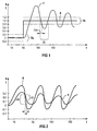
- beispielhafte Verläufe von Soll- und Istwert, wobei beide Größen eine Schwingung aufweisen und zum Einsatz bei der Erfindung Kenngrößen zur Bestimmung der Änderungsgeschwindigkeit von Soll- und Istwert eingezeichnet sind,
- FIG 3
- einen weiteren beispielhaften zeitlichen Verlauf des Istwerts, wobei zum Einsatz bei der Erfindung als Kenngrößen eine Anstiegszeit sowie ein zweiter vorgegebener Zeitraum angegeben sind, und
- FIG 4
- einen erfindungsgemäßen Regler.
- FIG. 1
- the graphical representation of an exemplary course for the actual value, wherein for use in the invention as parameters a dwell time and a first predetermined period are given,
- FIG. 2
- exemplary characteristics of desired value and actual value, wherein both variables have a vibration and for use in the invention characteristics for determining the rate of change of setpoint and actual value are plotted,
- FIG. 3
- a further exemplary time profile of the actual value, wherein for use in the invention as characteristics a rise time and a second predetermined period are given, and
- FIG. 4
- a controller according to the invention.
In FIG 1 ist beispielhaft der zeitliche Verlauf eines Istwerts I dargestellt, welcher eine Schwingung aufweist und einen vorgegebenen Sollwert S auch über einen längeren Zeitraum nicht genügend gut annähert, sich also insbesondere nicht innerhalb eines Toleranzbandes Tb bewegt.In FIG. 1, the time profile of an actual value I is shown as an example, which has a vibration and does not approach a given setpoint value S well enough over a relatively long period of time, ie in particular does not move within a tolerance band Tb.
Die Darstellung der FIG 1 soll das zeitliche Verhalten von Soll- und Istwert einer geregelten Komponente einer technischen Anlage zeigen. Zum Zeitpunkt t = 50 (beispielsweise t = 50 Sek.) ändert sich der Sollwert S sprungartig von S = 0 auf S = 1 und bleibt ab dem Zeitpunkt t = 50 konstant. Bei einem geregelten System ist anzustreben, dass der Istwert I der zugehörigen Regelgröße dem zeitlichen Verlauf des Sollwerts S möglichst gut folgt, wobei zum einen der Sollwert S möglichst schnell erreicht werden soll, zum anderen aber auch ein zu starkes Über- und Unterschwingen des Istwerts I bezüglich des Sollwerts S vermieden werden muss, um ein stabiles, geregeltes System zu erhalten. Insbesondere ist zu vermeiden, dass der Istwert I Schwingungen aufweist, welche im Lauf der Zeit nicht abklingen und/oder deren Amplitude Werte aufweist, welche nicht innerhalb des Toleranzbandes Tb liegen oder dieses sogar weit überragen. Das Toleranzband Tb ist dem jeweiligen konkreten Einsatzbereich anzupassen und soll eine zulässige Abweichung des Istwerts I vom gewünschten Sollwert S während des Regelvorgangs widerspiegeln.The illustration of FIG 1 is intended to show the temporal behavior of the setpoint and actual value of a controlled component of a technical system. At the time t = 50 (for example, t = 50 sec.) The setpoint S changes abruptly from S = 0 to S = 1 and remains constant from the time t = 50. In the case of a regulated system, it is desirable that the actual value I of the associated controlled variable follow the time characteristic of the setpoint S as well as possible, with setpoint S being reached as quickly as possible, but also overshooting and undershooting of actual value I with respect to the set point S must be avoided in order to obtain a stable, regulated system. In particular, it must be avoided that the actual value I has vibrations which do not decay over time and / or whose amplitude has values which are not within the tolerance band Tb or even far exceed it. The tolerance band Tb is to be adapted to the respective specific area of application and should reflect an admissible deviation of the actual value I from the desired setpoint value S during the control process.
Die Grenzen des Toleranzbands Tb müssen dabei bezüglich des Sollwerts S nicht symmetrisch sein; sie können vielmehr den Erfordernissen eines konkreten Anwendungsfalls angepasst werden.The limits of the tolerance band Tb need not be symmetrical with respect to the setpoint S; they can rather be adapted to the requirements of a specific application.
Im Beispiel der FIG 1 kann aus dem zeitlichen Verhalten des Istwerts I geschlossen werden, dass der Verstärkungsfaktor Kp der zugrundeliegenden geregelten Komponente zu groß gewählt wurde, dass also der eingesetzte PI-Regler insbesondere auf eine durch die Differenz des Soll- und Istwerts bestimmte Regelabweichung mit einer zu großen Proportionalverstärkung reagiert, was zu der in FIG 1 beispielhaft illustrierten unerwünschten Schwingung des Istwerts I führt.In the example of FIG. 1, it can be concluded from the temporal behavior of the actual value I that the amplification factor Kp of the underlying controlled component was chosen too large, that is to say the PI controller used is in particular subject to a system deviation determined by the difference of the setpoint and actual value responding to a large proportional gain, which leads to the example illustrated in FIG. 1 unwanted vibration of the actual value I.
Um eine stabile Regelung zu erhalten, insbesondere, um die Anforderung an den zeitlichen Verlauf des Istwerts bezüglich des Toleranzbandes Tb erfüllen zu können, ist es erforderlich und bei der Erfindung vorgesehen, den Verstärkungsfaktor Kp laufend zu verändern, bis der Ist-Wert I der Regelgröße innerhalb des Toleranzbands Tb verbleibt. Im vorliegenden Beispiel ist der Verstärkungsfaktor Kp zu erniedrigen. Dies ist insbesondere deshalb angezeigt, da eine Verweil-Zeit T11 kleiner ist als ein erster vorgegebener Zeitraum T1. Man kann dies dahingehend interpretieren, dass der Istwert I während seines zeitlichen Verlaufs "zu schnell" durch das Toleranzband Tb hindurch tritt, was auf eine unerwünschte Schwingung des Istwerts I schließen lässt. Der Vergleichszeitraum (erster vorgegebener Zeitraum T1) wird dabei vorteilhaft mittels der Streckenzeitkonstanten der zu regelnden Komponente ermittelt, so dass der Tatsache Rechnung getragen werden kann, dass der vorher genannte Begriff "zu schnell" relativ zur systembedingten Verzögerung der zu regelnden Komponente definiert werden sollte.In order to obtain a stable control, in particular in order to be able to fulfill the requirement on the time profile of the actual value with respect to the tolerance band Tb, it is necessary and in the invention provided to continuously change the amplification factor Kp until the actual value I of the controlled variable remains within the tolerance band Tb. In the present example, the gain Kp is to be lowered. This is particularly indicated because a dwell time T11 is less than a first predetermined time period T1. This can be interpreted as meaning that the actual value I "passes too fast" through the tolerance band Tb during its time course, which indicates an unwanted oscillation of the actual value I. The comparison period (first predetermined period T1) is advantageously determined by means of the time constant of the component to be controlled, so that the fact that the previously mentioned term "too fast" should be defined relative to the system-related delay of the component to be controlled can be taken into account.
Die laufende Erniedrigung des Verstärkungsfaktors Kp wird beendet, sobald der zeitliche Verlauf des Istwerts sich im Toleranzband Tb bewegt und in diesem verbleibt. Alternativ oder in Ergänzung kann die Erniedrigung des Verstärkungsfaktors Kp durch Multiplikation mit einem konstanten Wert zwischen 0 und 1 erfolgen und zwar jedes mal dann, wenn der aktuelle Istwert durch das Toleranzband hindurch getreten ist.The current reduction of the gain Kp is terminated as soon as the time course of the actual value moves in the tolerance band Tb and remains in this. Alternatively or in addition, the reduction of the amplification factor Kp can be carried out by multiplication by a constant value between 0 and 1, namely whenever the current actual value has passed through the tolerance band.
In FIG 2 sind die zeitlichen Verläufe von Sollwert S und Istwert I dargestellt, wobei der Sollwert S eine Schwingung aufweist, also insbesondere im Unterschied zur FIG 1 keine Bereiche konstanten Verlaufs aufweist.In FIG. 2, the time profiles of setpoint value S and actual value I are shown, the setpoint value S having a vibration, that is to say, in particular, in contrast to FIG. 1, having no regions of constant progression.
Infolgedessen weist auch der Istwert I, welcher dem zeitlichen Verlauf des Sollwerts S möglichst gut folgen soll, ein schwingendes Verhalten auf.As a result, the actual value I, which should follow the temporal course of the desired value S as well as possible, also exhibits oscillating behavior.
In diesem Beispiel ist aus der Schwingung des Istwerts I nicht zwangsläufig zu schließen, dass der Verstärkungsfaktor Kp des eingesetzten PI-Reglers zu groß eingestellt ist und deshalb die Schwingung des Istwerts I verursacht ist. Eine Erniedrigung des Verstärkungsfaktors Kp in einem derartigen Fall könnte zu einem völlig unbefriedigenden Regelverhalten führen.In this example, it can not necessarily be concluded from the oscillation of the actual value I that the amplification factor Kp of the PI controller used is set too high and therefore the oscillation of the actual value I is caused. A lowering of the amplification factor Kp in such a case could lead to a completely unsatisfactory control behavior.
Es ist vielmehr zu prüfen, ob der momentan eingestellte Wert des Verstärkungsfaktors Kp für die Schwingung des Istwerts I verantwortlich ist, oder ob die Schwingung des Istwerts I lediglich verursacht ist durch das gewünschte Folgen des Istwerts I in Bezug auf den im Beispiel der FIG 2 schwingenden Sollwert S.It is rather to check whether the currently set value of the amplification factor Kp is responsible for the oscillation of the actual value I, or whether the oscillation of the actual value I is only caused by the desired consequences of the actual value I with respect to the oscillating in the example of FIG Setpoint S.
Der Verstärkungsfaktor Kp soll nur dann erniedrigt werden, wenn sich der Istwert I schneller ändert als der Sollwert S.The amplification factor Kp should only be lowered if the actual value I changes faster than the setpoint S.
Zur Bestimmung der genannten Änderungsgeschwindigkeiten von Sollwert S und Istwert I sind in der FIG 2 beispielhaft bezüglich eines Bezugszeitraums Δt die Änderung ΔS des Sollwerts S während des Bezugszeitraums Δt sowie die Änderung ΔI des Istwerts I dargestellt. Der Quotient aus ΔS und Δt bzw. ΔI und Δt ermöglicht eine Ermittlung der genannten Änderungsgeschwindigkeiten von Istwert I und Sollwert S.To determine the aforementioned rates of change of the setpoint value S and the actual value I, the change ΔS of the setpoint value S during the reference period Δt and the change ΔI of the actual value I are shown by way of example with reference to a reference period Δt. The quotient of .DELTA.S and .DELTA.t or .DELTA.I and .DELTA.t allows a determination of the aforementioned rates of change of actual value I and setpoint S.
Im Beispiel der FIG 2 ist die Änderungsgeschwindigkeit des Istwerts I (erste Änderungsgeschwindigkeit) kleiner als die Änderungsgeschwindigkeit des Sollwert S (zweite Änderungsgeschwindigkeit). Es kann daher darauf geschlossen werden, dass die Schwingungen des Istwerts I zurückzuführen sind auf Schwingungen des Sollwert S, so dass im vorliegenden Fall der Verstärkungsfaktor Kp des eingesetzten PI-Reglers nicht zu erniedrigen ist.In the example of FIG. 2, the rate of change of the actual value I (first rate of change) is smaller than that Rate of change of setpoint S (second rate of change). It can therefore be concluded that the oscillations of the actual value I are due to oscillations of the setpoint S, so that in the present case, the gain Kp of the PI controller used is not to be lowered.
In FIG 3 ist beispielhaft der zeitliche Verlauf des Istwerts I dargestellt, wobei dieser den vorgegebenen Sollwert S nur relativ langsam erreicht.In FIG. 3, the time profile of the actual value I is shown by way of example, with the latter only reaching the predetermined desired value S relatively slowly.
Bei einem derartigen zeitlichen Verhalten des Istwerts I kann darauf geschlossen werden, dass der Verstärkungsfaktor Kp des eingesetzten PI-Reglers zu klein eingestellt ist, dass also der PI-Regler mit einer zu kleinen Proportionalverstärkung auf die Differenz zwischen Soll- und Istwert (Regelabweichung) reagiert.With such a temporal behavior of the actual value I can be concluded that the gain Kp of the PI controller used is set too small, so that the PI controller reacts with a too small proportional gain to the difference between the setpoint and actual value (control deviation) ,
Um festzustellen, ob der zeitliche Verlauf des Istwerts I dem Sollwert S zu langsam folgt und der Verstärkungsfaktor Kp daher zu erhöhen ist, sind im Beispiel der FIG 3 Kenngrößen eingezeichnet, nämlich eine Anstiegszeit T22 und ein zweiter vorgegebener Zeitraum T2.In order to determine whether the time profile of the actual value I follows the setpoint value S too slowly and therefore the amplification factor Kp is to be increased, characteristic values are shown in the example of FIG. 3, namely a rise time T22 and a second predefined time period T2.
Die Anstiegszeit T22 umfasst dabei den Zeitraum von Beginn einer Änderung des Sollwerts S bis zum Erreichen eines momentanen Werts des Istwerts I innerhalb des Toleranzbands. Wenn diese Anstiegszeit T22 größer ist als der zweite vorgegebene Zeitraum T2, dann reagiert die mittels eines PI-Reglers geregelte Komponente auf eine Sollwertänderung zu langsam und der Verstärkungsfaktor Kp ist zu erhöhen.The rise time T22 comprises the period from the beginning of a change of the setpoint value S until a current value of the actual value I within the tolerance band is reached. If this rise time T22 is greater than the second predetermined time period T2, then the component controlled by a PI controller responds to a setpoint change too slow and the gain Kp is to increase.
Vorteilhaft wird der zweite vorgegebene Zeitraum T2 aus den Streckenzeitkonstanten der zu regelnden Komponente ermittelt, so dass in Abhängigkeit von der systembedingten Verzögerung der zu regelnden Komponente (Regelstrecke) technisch richtig beurteilt werden kann, ob die Anstiegszeit T22 des Istwerts I zu groß und der Verstärkungsfaktor Kp daher zu erhöhen ist.Advantageously, the second predetermined time period T2 is determined from the time constants of the component to be controlled, so that technically correct depending on the system-related delay of the component to be controlled (controlled system) It can be judged whether the rise time T22 of the actual value I is too large and therefore the amplification factor Kp is to be increased.
Die laufende Erhöhung des Verstärkungsfaktors Kp im Falle der FIG 3 erfolgt solange, bis der Istwert I innerhalb des Toleranzbands Tb verbleibt.The continuous increase of the amplification factor Kp in the case of FIG. 3 takes place until the actual value I remains within the tolerance band Tb.
FIG 4 zeigt einen erfindungsgemäßen Regler R.4 shows a regulator R. according to the invention.
Der Regler R dient zur Regelung mindestens einer Komponente einer technischen Anlage und ist als PI-Regler ausgebildet.The controller R is used to control at least one component of a technical system and is designed as a PI controller.
Der Regler R umfasst als Reglerparameter einen Verstärkungsfaktor Kp und eine Nachstellzeit Tn.The controller R comprises a gain factor Kp and a reset time Tn as controller parameters.
Ein erster Reglereingang E1 ist mit einer vorgegebenen Nachstellzeit Tn beaufschlagbar.A first controller input E1 can be acted upon by a predetermined reset time Tn.
Einem zweiten Reglereingang E2 ist der Verstärkungsfaktor Kp zuführbar und ein dritter Reglereingang E3 dient dem Erfassen eines Sollwerts S einer Regelgröße der Komponente.A second controller input E2, the gain Kp can be fed and a third controller input E3 is used to detect a desired value S of a controlled variable of the component.
Der Regler R weist außerdem eine Adaptionseinheit A, mittels welcher während des Betriebs der technischen Anlage laufend der Istwert I der Regelgröße bestimmbar und der Verstärkungsfaktor Kp in Abhängigkeit vom zeitlichen Verhalten des Istwerts I veränderbar ist, bis der Istwert I der Regelgröße innerhalb eines Toleranzbandes Tb bezüglich des Sollwert S verbleibt.The regulator R also has an adaptation unit A, by means of which the actual value I of the controlled variable can be determined during the operation of the technical system and the amplification factor Kp can be varied as a function of the time behavior of the actual value I until the actual value I of the controlled variable is within a tolerance band Tb the setpoint S remains.
Zum Beginn des Regelvorgangs wird der Eingang E2 mit einem Anfangswert Kp0 für den Verstärkungsfaktor Kp beaufschlagt. Dieser Anfangswert Kp0 wird dann während des Regelvorgangs laufend in Abhängigkeit vom zeitlichen Verhalten des Istwerts verändert, bis der Istwert I der Regelgröße innerhalb eines Toleranzbandes Tb bezüglich des Sollwert S verbleibt. Der Regler R umfasst weiterhin einen Reglerausgang Y, welcher eine Stellgröße liefert, mittels welcher die zu regelnde Komponente angesteuert wird, um ein gewünschtes Verhalten des Istwerts I zu erreichen.At the beginning of the control process, the input E2 is supplied with an initial value Kp0 for the amplification factor Kp. This initial value Kp0 is then continuously varied during the control process as a function of the time behavior of the actual value until the actual value I of the controlled variable remains within a tolerance band Tb with respect to the desired value S. The controller R further comprises a controller output Y, which a Command value provides, by means of which the component to be controlled is controlled in order to achieve a desired behavior of the actual value I.
Es sei darauf hingewiesen, dass die Begriffe Reglereingang (E1,E2,E3) nicht einschränkend dahingehend auszulegen sind, dass bei einem erfindungsgemäßen Regler ein physikalischer Anschluss vorliegen muss, an welchen die genannten Größen anzulegen sind.It should be noted that the terms controller input (E1, E2, E3) are not to be construed restrictively to the effect that in a controller according to the invention a physical connection must be present, to which the variables mentioned are to be applied.
Der Begriff Reglereingang soll vielmehr alle Mittel umfassen, mittels welchen der PI-Regler mit den genannten Größen versorgt werden kann.Rather, the term controller input should encompass all means by means of which the PI controller can be supplied with the mentioned variables.
Im Falle einer analogen Realisierung des PI-Regler, beispielsweise mittels beschalteter Operationsverstärker, soll der Begriff Reglereingang alle Beschaltungsmöglichkeiten des Operationsverstärkers mittels elektronischer Bauelemente umfassen, welche in ihrer Zusammenschaltung einen bestimmten Wert für mindestens eine der Größen Tn und Kp realisieren.In the case of an analog implementation of the PI controller, for example by means of wired operational amplifiers, the term controller input is intended to encompass all circuit possibilities of the operational amplifier by means of electronic components which, in their interconnection, realize a specific value for at least one of the variables Tn and Kp.
Im Falle einer digitalen Realisierung des PI-Reglers, beispielsweise auf einem Digitalrechner, soll der Begriff Reglereingang alle Speicherbereiche umfassen, in welche Werte für die Reglerparameter Tn und Kp geschrieben und/oder aus welchen diese Werte ausgelesen werden.In the case of a digital realization of the PI controller, for example on a digital computer, the term controller input should encompass all memory areas into which values for the controller parameters Tn and Kp are written and / or from which these values are read out.
Claims (8)
- Method for controlling at least one component of a technical plant by means of a PI controller that has a control ratio (Kp) and an integral-action time (Tn) as control parameters, characterised by the following steps:a) the integral-action time (Tn) is predefined,b) an initial value (Kp0) of the control ratio (Kp) is predefined,c) at least one set value (S) of a control variable of the component is predefined andd) during operation of the technical plant, the actual value (I) of the control variable is determined and the control ratio (Kp) is changed as a function of the temporal response of the actual value (I) until the actual value (I) of the control variable remains within a tolerance band (Tb) relative to the set value (S), with the control ratio (Kp) being reduced if the temporal response of the actual value (I) has a dwell time (T11) during which the actual value (I) assumes a value within the tolerance band that is smaller than a first defined time period (T1).
- Method in accordance with claim 1,
characterised in that
the integral-action time (Tn) is determined from the system time constants (K1, K2, ..., K3), particularly from the sum of the system time constants of the component to be controlled. - Method in accordance with Claim 1 or 2,
characterised in that
in step d) the control ratio (Kp) is only reduced if additionally a first change rate (v1) of the actual value (I) is greater than a second change rate (v2) of the set value (SO). - Method in accordance with one of claims 1 to 3,
characterised in that
in step d) the control ratio (Kp) is increased if the temporal response of the actual value (I) has a rise time (T22) that includes the time period from the start of a change of the set value (S) up until reaching an instantaneous value of the actual value (I) within the tolerance band that is greater than a second predefined time period (T2). - Controller (R) for controlling at least one component of a technical plant, that is designed as a PI controller and has a control ratio (Kp) and an integral-action time (Tn) as control parameters,
characterised by- a first controller input (E1) by means of which the controller (R) can be supplied with a defined value for the integral-action time (Tn),- a second controller input (E2) by means of which the controller (R) can be supplied with the control ratio (Kp),- a third controller input (E3) by means of which the controller (R) can be supplied with a set value (S) of a control variable of the component, and- an adaption unit (A) that during the operation of the technical plant constantly applies the actual value (I) of the control variable (U) and by means of which the control ratio (Kp) can be constantly changed as a function of the temporal response of the actual value (I), until the actual value (I) of the control variable remains within a tolerance band (Tb) relative to the set value (S), with the control ratio (Kp) being reduced by means of the adaption unit (A) if the temporal response of the actual value (I) has a dwell time (T11) during which the actual value (I) assumes a value within the tolerance band that is smaller than a first predefined time period (T1). - Controller in accordance with claim 5,
characterised in that
the integral-action time (Tn) is determined from system time constants (K1, K2, ..., K3), in particular from the sum of the system time constants of the component to be controlled. - Controller in accordance with claim 5 or 6,
characterised in that
the control ratio (Kp) is then only reduced by means of the adaption unit (A) if additionally a first change rate (v1) of the actual value (I) is greater than a second change rate (v2) of the set value (S). - Controller in accordance with one of claims 5 to 7,
characterised in that
the control ratio (Kp) is increased by the adaption unit (A) if the temporal response of the actual value (I) has a rise time (T22), that includes the time period from the start of a change of the set value (S) until reaching an instantaneous value of the actual value (I) within the tolerance band, that is greater than a second defined time period (T2).
Applications Claiming Priority (3)
| Application Number | Priority Date | Filing Date | Title |
|---|---|---|---|
| DE10213533A DE10213533A1 (en) | 2002-03-26 | 2002-03-26 | Method and controller for regulating at least one component of a technical system |
| DE10213533 | 2002-03-26 | ||
| PCT/DE2003/000793 WO2003081348A1 (en) | 2002-03-26 | 2003-03-12 | Method and controller for the adaptive control of at least one component of a technical plant |
Publications (2)
| Publication Number | Publication Date |
|---|---|
| EP1490735A1 EP1490735A1 (en) | 2004-12-29 |
| EP1490735B1 true EP1490735B1 (en) | 2006-11-02 |
Family
ID=28050871
Family Applications (1)
| Application Number | Title | Priority Date | Filing Date |
|---|---|---|---|
| EP03711843A Expired - Lifetime EP1490735B1 (en) | 2002-03-26 | 2003-03-12 | Method and controller for the adaptive control of at least one component of a technical plant |
Country Status (7)
| Country | Link |
|---|---|
| US (1) | US7395125B2 (en) |
| EP (1) | EP1490735B1 (en) |
| AT (1) | ATE344476T1 (en) |
| AU (1) | AU2003218619A1 (en) |
| DE (2) | DE10213533A1 (en) |
| ES (1) | ES2276050T3 (en) |
| WO (1) | WO2003081348A1 (en) |
Cited By (3)
| Publication number | Priority date | Publication date | Assignee | Title |
|---|---|---|---|---|
| EP2474873A1 (en) | 2011-01-11 | 2012-07-11 | Siemens Aktiengesellschaft | Method and device for filtering a signal and regulating device for a process |
| WO2012095407A1 (en) | 2011-01-11 | 2012-07-19 | Siemens Aktiengesellschaft | Method and device for filtering a signal and control device for a process |
| DE102011003477A1 (en) | 2011-02-01 | 2012-08-02 | Siemens Aktiengesellschaft | Method for filtering signal for automation of control structure in power plant, involves continuously outputting predefined system time constant and filtered output signal as dead band signal, which corresponds to smoothed input signal |
Families Citing this family (7)
| Publication number | Priority date | Publication date | Assignee | Title |
|---|---|---|---|---|
| DE102004029790B4 (en) * | 2004-06-19 | 2014-05-15 | Etel S.A. | Method and device for optimizing controller parameters |
| DE102005043952A1 (en) * | 2005-09-15 | 2007-04-05 | Danfoss A/S | Heat exchanger and method for controlling a heat exchanger |
| DE102005047932A1 (en) * | 2005-10-06 | 2007-04-12 | Zf Friedrichshafen Ag | Control system e.g. automatic transmission, controlling method for motor vehicle, involves determining amplitude and time offset processes from evaluation of control deviation to execute adaptation and/or optimization of control of system |
| WO2009056568A1 (en) * | 2007-10-29 | 2009-05-07 | Siemens Aktiengesellschaft | Method for monitoring the quality of a control system in a power plant |
| US9851118B2 (en) | 2012-04-05 | 2017-12-26 | Carrier Corporation | HVAC system relay autotuning and verification |
| US20140266081A1 (en) * | 2013-03-14 | 2014-09-18 | Infineon Technologies Austria Ag | Adaptive adjustment to output ripple in a dead zone |
| DE102013205356B4 (en) * | 2013-03-26 | 2016-07-07 | Siemens Aktiengesellschaft | Method for computer-aided control and / or regulation of a technical system |
Family Cites Families (15)
| Publication number | Priority date | Publication date | Assignee | Title |
|---|---|---|---|---|
| US3458821A (en) * | 1966-07-05 | 1969-07-29 | Ibm | Variable gain controller |
| US3798426A (en) * | 1971-12-20 | 1974-03-19 | Foxboro Co | Pattern evaluation method and apparatus for adaptive control |
| US4349868A (en) * | 1980-06-23 | 1982-09-14 | Hewlett-Packard Company | Sampled control loop with dynamic gain optimization |
| JPH06100125B2 (en) * | 1985-11-20 | 1994-12-12 | 株式会社日立製作所 | Air-fuel ratio controller |
| DE3636512A1 (en) * | 1986-10-27 | 1988-04-28 | Weiss Dieter | Electrical regulator (controller) |
| DE3811086A1 (en) * | 1987-04-03 | 1988-10-20 | Hitachi Ltd | PID CONTROL SYSTEM |
| US5587896A (en) * | 1990-07-16 | 1996-12-24 | The Foxboro Company | Self-tuning controller |
| US5229699A (en) * | 1991-10-15 | 1993-07-20 | Industrial Technology Research Institute | Method and an apparatus for PID controller tuning |
| JPH0635505A (en) * | 1992-07-16 | 1994-02-10 | Osayasu Sato | Automatic controller |
| US5363647A (en) * | 1992-10-13 | 1994-11-15 | Mitsubishi Denki Kabushiki Kaisha | Dual-sensor type air fuel ratio control system for internal combustion engine and catalytic converter diagnosis apparatus for the same |
| US5355305A (en) * | 1992-10-29 | 1994-10-11 | Johnson Service Company | Pattern recognition adaptive controller |
| DE69622177T2 (en) * | 1995-09-22 | 2002-10-31 | Rosemount Inc | ADAPTIVE OFFSET CONTROLLER |
| US5847952A (en) * | 1996-06-28 | 1998-12-08 | Honeywell Inc. | Nonlinear-approximator-based automatic tuner |
| DE19748718A1 (en) * | 1997-11-05 | 1999-05-06 | Hans Werner Dr Ing Philippsen | Self-adjusting device for process control system |
| US7472687B2 (en) * | 2002-11-01 | 2009-01-06 | Visteon Global Technologies, Inc. | System and method for pre-processing ionization signal to include enhanced knock information |
-
2002
- 2002-03-26 DE DE10213533A patent/DE10213533A1/en not_active Withdrawn
-
2003
- 2003-03-12 DE DE50305572T patent/DE50305572D1/en not_active Expired - Lifetime
- 2003-03-12 EP EP03711843A patent/EP1490735B1/en not_active Expired - Lifetime
- 2003-03-12 US US10/508,922 patent/US7395125B2/en not_active Expired - Fee Related
- 2003-03-12 AU AU2003218619A patent/AU2003218619A1/en not_active Abandoned
- 2003-03-12 WO PCT/DE2003/000793 patent/WO2003081348A1/en active IP Right Grant
- 2003-03-12 ES ES03711843T patent/ES2276050T3/en not_active Expired - Lifetime
- 2003-03-12 AT AT03711843T patent/ATE344476T1/en active
Cited By (4)
| Publication number | Priority date | Publication date | Assignee | Title |
|---|---|---|---|---|
| EP2474873A1 (en) | 2011-01-11 | 2012-07-11 | Siemens Aktiengesellschaft | Method and device for filtering a signal and regulating device for a process |
| WO2012095407A1 (en) | 2011-01-11 | 2012-07-19 | Siemens Aktiengesellschaft | Method and device for filtering a signal and control device for a process |
| DE102011003477A1 (en) | 2011-02-01 | 2012-08-02 | Siemens Aktiengesellschaft | Method for filtering signal for automation of control structure in power plant, involves continuously outputting predefined system time constant and filtered output signal as dead band signal, which corresponds to smoothed input signal |
| DE102011003477B4 (en) * | 2011-02-01 | 2015-07-02 | Siemens Aktiengesellschaft | Method and device for filtering a signal and control device for a process |
Also Published As
| Publication number | Publication date |
|---|---|
| DE10213533A1 (en) | 2003-10-16 |
| US7395125B2 (en) | 2008-07-01 |
| ATE344476T1 (en) | 2006-11-15 |
| DE50305572D1 (en) | 2006-12-14 |
| WO2003081348A1 (en) | 2003-10-02 |
| ES2276050T3 (en) | 2007-06-16 |
| US20050159825A1 (en) | 2005-07-21 |
| EP1490735A1 (en) | 2004-12-29 |
| AU2003218619A1 (en) | 2003-10-08 |
Similar Documents
| Publication | Publication Date | Title |
|---|---|---|
| DE3153303C2 (en) | Method and device for limiting the thermal stress on a steam turbine that occurs when there are changes in load | |
| DE102006007919A1 (en) | Method for operating a wind energy plant | |
| EP2579112A1 (en) | Regulating device | |
| EP1490735B1 (en) | Method and controller for the adaptive control of at least one component of a technical plant | |
| DE4104642C2 (en) | PID or PI controller | |
| EP2935877B1 (en) | Wind turbine and method for regulating the electrical moment of a wind turbine in the event of a grid fault | |
| EP0336095B1 (en) | Control method to prevent surge of a centrifugal compressor by means of venting by need | |
| DE19830341C1 (en) | Method for operating a control device and device for carrying out the method | |
| DE102006051352C5 (en) | Method for operating a wind energy plant | |
| EP2100196B1 (en) | Method for the adaptation of the control parameters of a drive controller to changed operating conditions | |
| EP2192685A1 (en) | Device and method for setting the parameters of an electronic motor control device automatically | |
| CH679235A5 (en) | ||
| DE3419725A1 (en) | METHOD FOR REGULATING A HYDRAULIC DEVICE | |
| EP1217472B1 (en) | Method for controlling a process having delay with compensation as well as control device for carrying out the method | |
| DE102014103027A1 (en) | Tracking controller for a V / f-controlled asynchronous machine | |
| EP0822332A1 (en) | Hydraulic power station | |
| DE4003522C2 (en) | Stepper motor in constant current operation and in live operation | |
| DE4322366A1 (en) | Control device | |
| DE102018115781B4 (en) | Method for regulating a fluid energy machine and a regulation arrangement, in particular for performing the method | |
| DE102011003477B4 (en) | Method and device for filtering a signal and control device for a process | |
| DE19601232A1 (en) | Control circuit regulating unit | |
| EP3511564B1 (en) | Method and system for controlling a wind energy plant | |
| EP3296820B1 (en) | Control device and method | |
| EP4253754A1 (en) | Method for operating a variable-speed pump | |
| EP3890177A1 (en) | Intermediate circuit inverter and control device for an intermediate circuit inverter |
Legal Events
| Date | Code | Title | Description |
|---|---|---|---|
| PUAI | Public reference made under article 153(3) epc to a published international application that has entered the european phase |
Free format text: ORIGINAL CODE: 0009012 |
|
| 17P | Request for examination filed |
Effective date: 20040715 |
|
| AK | Designated contracting states |
Kind code of ref document: A1 Designated state(s): AT BE BG CH CY CZ DE DK EE ES FI FR GB GR HU IE IT LI LU MC NL PT RO SE SI SK TR |
|
| AX | Request for extension of the european patent |
Extension state: AL LT LV MK |
|
| GRAP | Despatch of communication of intention to grant a patent |
Free format text: ORIGINAL CODE: EPIDOSNIGR1 |
|
| GRAS | Grant fee paid |
Free format text: ORIGINAL CODE: EPIDOSNIGR3 |
|
| GRAA | (expected) grant |
Free format text: ORIGINAL CODE: 0009210 |
|
| AK | Designated contracting states |
Kind code of ref document: B1 Designated state(s): AT BE BG CH CY CZ DE DK EE ES FI FR GB GR HU IE IT LI LU MC NL PT RO SE SI SK TR |
|
| PG25 | Lapsed in a contracting state [announced via postgrant information from national office to epo] |
Ref country code: FI Free format text: LAPSE BECAUSE OF FAILURE TO SUBMIT A TRANSLATION OF THE DESCRIPTION OR TO PAY THE FEE WITHIN THE PRESCRIBED TIME-LIMIT Effective date: 20061102 Ref country code: CZ Free format text: LAPSE BECAUSE OF FAILURE TO SUBMIT A TRANSLATION OF THE DESCRIPTION OR TO PAY THE FEE WITHIN THE PRESCRIBED TIME-LIMIT Effective date: 20061102 Ref country code: IE Free format text: LAPSE BECAUSE OF FAILURE TO SUBMIT A TRANSLATION OF THE DESCRIPTION OR TO PAY THE FEE WITHIN THE PRESCRIBED TIME-LIMIT Effective date: 20061102 Ref country code: RO Free format text: LAPSE BECAUSE OF FAILURE TO SUBMIT A TRANSLATION OF THE DESCRIPTION OR TO PAY THE FEE WITHIN THE PRESCRIBED TIME-LIMIT Effective date: 20061102 Ref country code: SK Free format text: LAPSE BECAUSE OF FAILURE TO SUBMIT A TRANSLATION OF THE DESCRIPTION OR TO PAY THE FEE WITHIN THE PRESCRIBED TIME-LIMIT Effective date: 20061102 Ref country code: SI Free format text: LAPSE BECAUSE OF FAILURE TO SUBMIT A TRANSLATION OF THE DESCRIPTION OR TO PAY THE FEE WITHIN THE PRESCRIBED TIME-LIMIT Effective date: 20061102 |
|
| REG | Reference to a national code |
Ref country code: GB Ref legal event code: FG4D Free format text: NOT ENGLISH |
|
| REG | Reference to a national code |
Ref country code: IE Ref legal event code: FG4D Free format text: LANGUAGE OF EP DOCUMENT: GERMAN |
|
| REG | Reference to a national code |
Ref country code: CH Ref legal event code: EP |
|
| REF | Corresponds to: |
Ref document number: 50305572 Country of ref document: DE Date of ref document: 20061214 Kind code of ref document: P |
|
| PG25 | Lapsed in a contracting state [announced via postgrant information from national office to epo] |
Ref country code: DK Free format text: LAPSE BECAUSE OF FAILURE TO SUBMIT A TRANSLATION OF THE DESCRIPTION OR TO PAY THE FEE WITHIN THE PRESCRIBED TIME-LIMIT Effective date: 20070202 Ref country code: BG Free format text: LAPSE BECAUSE OF FAILURE TO SUBMIT A TRANSLATION OF THE DESCRIPTION OR TO PAY THE FEE WITHIN THE PRESCRIBED TIME-LIMIT Effective date: 20070202 Ref country code: SE Free format text: LAPSE BECAUSE OF FAILURE TO SUBMIT A TRANSLATION OF THE DESCRIPTION OR TO PAY THE FEE WITHIN THE PRESCRIBED TIME-LIMIT Effective date: 20070202 |
|
| GBT | Gb: translation of ep patent filed (gb section 77(6)(a)/1977) |
Effective date: 20070117 |
|
| PG25 | Lapsed in a contracting state [announced via postgrant information from national office to epo] |
Ref country code: PT Free format text: LAPSE BECAUSE OF FAILURE TO SUBMIT A TRANSLATION OF THE DESCRIPTION OR TO PAY THE FEE WITHIN THE PRESCRIBED TIME-LIMIT Effective date: 20070402 |
|
| ET | Fr: translation filed | ||
| REG | Reference to a national code |
Ref country code: ES Ref legal event code: FG2A Ref document number: 2276050 Country of ref document: ES Kind code of ref document: T3 |
|
| REG | Reference to a national code |
Ref country code: IE Ref legal event code: FD4D |
|
| PLBE | No opposition filed within time limit |
Free format text: ORIGINAL CODE: 0009261 |
|
| STAA | Information on the status of an ep patent application or granted ep patent |
Free format text: STATUS: NO OPPOSITION FILED WITHIN TIME LIMIT |
|
| 26N | No opposition filed |
Effective date: 20070803 |
|
| BERE | Be: lapsed |
Owner name: SIEMENS A.G. Effective date: 20070331 |
|
| PG25 | Lapsed in a contracting state [announced via postgrant information from national office to epo] |
Ref country code: BE Free format text: LAPSE BECAUSE OF NON-PAYMENT OF DUE FEES Effective date: 20070331 |
|
| PG25 | Lapsed in a contracting state [announced via postgrant information from national office to epo] |
Ref country code: MC Free format text: LAPSE BECAUSE OF NON-PAYMENT OF DUE FEES Effective date: 20070331 |
|
| PG25 | Lapsed in a contracting state [announced via postgrant information from national office to epo] |
Ref country code: GR Free format text: LAPSE BECAUSE OF FAILURE TO SUBMIT A TRANSLATION OF THE DESCRIPTION OR TO PAY THE FEE WITHIN THE PRESCRIBED TIME-LIMIT Effective date: 20070203 |
|
| PG25 | Lapsed in a contracting state [announced via postgrant information from national office to epo] |
Ref country code: EE Free format text: LAPSE BECAUSE OF FAILURE TO SUBMIT A TRANSLATION OF THE DESCRIPTION OR TO PAY THE FEE WITHIN THE PRESCRIBED TIME-LIMIT Effective date: 20061102 |
|
| REG | Reference to a national code |
Ref country code: CH Ref legal event code: PCAR Free format text: SIEMENS SCHWEIZ AG;INTELLECTUAL PROPERTY FREILAGERSTRASSE 40;8047 ZUERICH (CH) |
|
| PG25 | Lapsed in a contracting state [announced via postgrant information from national office to epo] |
Ref country code: LU Free format text: LAPSE BECAUSE OF NON-PAYMENT OF DUE FEES Effective date: 20070312 Ref country code: CY Free format text: LAPSE BECAUSE OF FAILURE TO SUBMIT A TRANSLATION OF THE DESCRIPTION OR TO PAY THE FEE WITHIN THE PRESCRIBED TIME-LIMIT Effective date: 20061102 |
|
| PG25 | Lapsed in a contracting state [announced via postgrant information from national office to epo] |
Ref country code: HU Free format text: LAPSE BECAUSE OF FAILURE TO SUBMIT A TRANSLATION OF THE DESCRIPTION OR TO PAY THE FEE WITHIN THE PRESCRIBED TIME-LIMIT Effective date: 20070503 |
|
| PG25 | Lapsed in a contracting state [announced via postgrant information from national office to epo] |
Ref country code: DE Free format text: LAPSE BECAUSE OF NON-PAYMENT OF DUE FEES Effective date: 20111001 |
|
| PGFP | Annual fee paid to national office [announced via postgrant information from national office to epo] |
Ref country code: CH Payment date: 20120614 Year of fee payment: 10 |
|
| PGFP | Annual fee paid to national office [announced via postgrant information from national office to epo] |
Ref country code: AT Payment date: 20130212 Year of fee payment: 11 |
|
| REG | Reference to a national code |
Ref country code: CH Ref legal event code: PL |
|
| PG25 | Lapsed in a contracting state [announced via postgrant information from national office to epo] |
Ref country code: CH Free format text: LAPSE BECAUSE OF NON-PAYMENT OF DUE FEES Effective date: 20130331 Ref country code: LI Free format text: LAPSE BECAUSE OF NON-PAYMENT OF DUE FEES Effective date: 20130331 |
|
| REG | Reference to a national code |
Ref country code: AT Ref legal event code: MM01 Ref document number: 344476 Country of ref document: AT Kind code of ref document: T Effective date: 20140312 |
|
| PG25 | Lapsed in a contracting state [announced via postgrant information from national office to epo] |
Ref country code: AT Free format text: LAPSE BECAUSE OF NON-PAYMENT OF DUE FEES Effective date: 20140312 |
|
| REG | Reference to a national code |
Ref country code: FR Ref legal event code: PLFP Year of fee payment: 13 |
|
| PGFP | Annual fee paid to national office [announced via postgrant information from national office to epo] |
Ref country code: IT Payment date: 20150328 Year of fee payment: 13 Ref country code: NL Payment date: 20150303 Year of fee payment: 13 |
|
| PGFP | Annual fee paid to national office [announced via postgrant information from national office to epo] |
Ref country code: FR Payment date: 20150311 Year of fee payment: 13 Ref country code: GB Payment date: 20150312 Year of fee payment: 13 |
|
| PGFP | Annual fee paid to national office [announced via postgrant information from national office to epo] |
Ref country code: ES Payment date: 20150409 Year of fee payment: 13 Ref country code: DE Payment date: 20150513 Year of fee payment: 13 |
|
| REG | Reference to a national code |
Ref country code: DE Ref legal event code: R119 Ref document number: 50305572 Country of ref document: DE |
|
| REG | Reference to a national code |
Ref country code: NL Ref legal event code: MM Effective date: 20160401 |
|
| GBPC | Gb: european patent ceased through non-payment of renewal fee |
Effective date: 20160312 |
|
| REG | Reference to a national code |
Ref country code: FR Ref legal event code: ST Effective date: 20161130 |
|
| PG25 | Lapsed in a contracting state [announced via postgrant information from national office to epo] |
Ref country code: FR Free format text: LAPSE BECAUSE OF NON-PAYMENT OF DUE FEES Effective date: 20160331 Ref country code: GB Free format text: LAPSE BECAUSE OF NON-PAYMENT OF DUE FEES Effective date: 20160312 Ref country code: NL Free format text: LAPSE BECAUSE OF NON-PAYMENT OF DUE FEES Effective date: 20160401 |
|
| PG25 | Lapsed in a contracting state [announced via postgrant information from national office to epo] |
Ref country code: IT Free format text: LAPSE BECAUSE OF NON-PAYMENT OF DUE FEES Effective date: 20160312 |
|
| REG | Reference to a national code |
Ref country code: ES Ref legal event code: FD2A Effective date: 20170428 |
|
| PG25 | Lapsed in a contracting state [announced via postgrant information from national office to epo] |
Ref country code: ES Free format text: LAPSE BECAUSE OF NON-PAYMENT OF DUE FEES Effective date: 20160313 |
|
| PGFP | Annual fee paid to national office [announced via postgrant information from national office to epo] |
Ref country code: TR Payment date: 20150312 Year of fee payment: 13 |
|
| PG25 | Lapsed in a contracting state [announced via postgrant information from national office to epo] |
Ref country code: DE Free format text: LAPSE BECAUSE OF NON-PAYMENT OF DUE FEES Effective date: 20161001 |
|
| PG25 | Lapsed in a contracting state [announced via postgrant information from national office to epo] |
Ref country code: TR Free format text: LAPSE BECAUSE OF NON-PAYMENT OF DUE FEES Effective date: 20160312 |