EP3296820A1 - Control device and method - Google Patents
Control device and method Download PDFInfo
- Publication number
- EP3296820A1 EP3296820A1 EP16189313.6A EP16189313A EP3296820A1 EP 3296820 A1 EP3296820 A1 EP 3296820A1 EP 16189313 A EP16189313 A EP 16189313A EP 3296820 A1 EP3296820 A1 EP 3296820A1
- Authority
- EP
- European Patent Office
- Prior art keywords
- value
- control
- controller
- control device
- level
- Prior art date
- Legal status (The legal status is an assumption and is not a legal conclusion. Google has not performed a legal analysis and makes no representation as to the accuracy of the status listed.)
- Granted
Links
Images


Classifications
-
- G—PHYSICS
- G05—CONTROLLING; REGULATING
- G05B—CONTROL OR REGULATING SYSTEMS IN GENERAL; FUNCTIONAL ELEMENTS OF SUCH SYSTEMS; MONITORING OR TESTING ARRANGEMENTS FOR SUCH SYSTEMS OR ELEMENTS
- G05B5/00—Anti-hunting arrangements
- G05B5/01—Anti-hunting arrangements electric
Definitions
- the invention relates to a control device and a control method, wherein a dead zone element is connected upstream of a regulator, according to the preamble of claim 1 or the preamble of claim 6.
- tanks for example tanks or reactors
- the inlet of which is subject to a fluctuating volume flow and to which a continuous valve in the drain is used for filling level control.
- control systems without compensation, ie they are not asymptotically stable without controller or in other words, there is no asymptotic approach to a new end position within the control range for a manipulated variable jump. In manual operation of the controller such systems therefore require constant attention of the system operator.
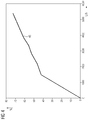
- abscissa and ordinate is in FIG. 1 spanned a complex s-plane, where the real parts are plotted on the abscissa labeled "Real Axis” and the imaginary parts are plotted on the ordinate labeled "Imag Axis”.
- Closing the loop creates a complex pair of poles that can only be shifted to the left to a limited extent by adjusting the regulator before it drifts outward, typically leaving weakly damped oscillations at a rather slow frequency.
- the poles 3, 4 of the closed loop are marked by squares. With increasing controller gain, they move along the root locus 5 away from the poles 1, 2 of the open loop. This means that unwanted continuous vibrations can occur. If one would increase the gain even further from the magnitude optimum shown here, the complex pole pair 3, 4 moves only a little to the left, that is, the control loop is only a little faster, but moves away from the real axis up or down , that is the damping is getting worse. In practice, however, the I-component in the regulator is frequently used because the steady-state deviations of a pure P-regulator would be so great in typical system designs that they could not be tolerated.
- FIG. 2 the step response of the closed loop with the in FIG. 1 5.
- time (seconds) the time in seconds
- Amplitude plotted the normalized amplitude of the controlled variable.
- the closed loop in a course 10 of the controlled variable shows an overshoot 11 of more than 40%. Therefore, in the analysis of the quality of control of process plants, fill level control systems are particularly frequently encountered due to poor key figures.
- a low pass filter for the noisy level measurement would be desirable in terms of calming the valve movements, but would represent a further delay with destabilizing effect.
- the use of a conventional dead zone in unbalanced control systems would typically result in a working movement of the regulator at the top or bottom of the deadband, which would be completely contrary to the objective of a buffer level control.
- a valve For use in control circuits, in which, for example, a valve is used as a mechanical actuator, is from the EP 2 579 112 B1 It is known to connect a deadband element to a linear regulator in order to achieve a reduction in the frequency of control actions in the steady state of the control. This leads to a reduction of energy consumption and wear on the control valve used.
- the energy consumption is directly dependent on the traversed paths, that is, the time integral of the travel.
- the consumption of compressed air is proportional to the travels traveled against a spring force, if it is a single-acting pneumatic drive.
- the reduction of control actions is achieved by the following characteristic of the known dead band member: If a control loop deviation exceeds a first threshold value, the dead zone member is automatically deactivated, whereby in the deactive state a control deviation carried over the deadband member is unaffected by a set dead band. If, after that, the control deviation falls below a second threshold, which is smaller than the first threshold, the dead zone member is automatically reactivated.
- a second threshold which is smaller than the first threshold
- the invention has for its object to provide a device and a method for controlling the level in a container which serves as a buffer memory, with which the uniformity of the process can be improved from the container.
- the value of the level is recorded as the actual value of the controlled variable.
- An inflow value which corresponds to the volume flow in the inlet to the container, is also determined. This can be a flow measurement somewhere in the pipeline of the inlet, the speed of a pump or the position of a valve in the inlet.
- the I component of the previously used PI controller is replaced by a correction of the control variable determined by the controller, a type of feedforward control, which is dimensioned as a function of the feed value. This measure ensures that the corrected manipulated variable of the controller is already approximately at a reasonable value for each realistic feed quantity, and reduces the remaining system deviation to a tolerable level when using a pure P-controller. In this case, a static disturbance variable connection can already be sufficient, which is preferably guided via a characteristic element with a non-linear characteristic.
- a PI controller with a comparatively small selected I component is also suitable for the control device, ie. H. an I component, which is preferably chosen to be smaller than half of the I component of a regulator, which was designed as described above, according to the optimum magnitude.
- the system dynamics are improved, which otherwise - as described above - could be problematic due to the combination of the I component of the controller designed, for example, according to magnitude optimum with an integrating or quasi-integrating level control system.
- a characteristic element whose characteristic is empirically predetermined is used.
- a variety of different feed rates are set, which may occur in practical operation of the buffer tank, and to determine the respective positions of the drain valve, which are required to fill the level at the respective set inlet values at least reasonably constant.
- a control valve with pneumatic drive can be used in the control loop to set the volume flow in the drain.
- these are particularly advantageous for reasons of explosion protection.
- an internal dead zone of an electropneumatic positioner used to adjust the valve and due to a resulting, for example by static friction on a stuffing box drag error they have a problematic for conventional level control dynamics.
- Even nonlinearities of the valve characteristic have so far a regulation in use complicate a control valve with pneumatic drive in addition.
- control valves with pneumatic drive can be used to advantage, without the described properties would lead to problems.
- the feed signal that is to say in the case of discrete-time control, the sequence of detected feed-in values, can be smoothed via a low-pass filter and, if desired, also greatly delayed.
- a method for controlling the level in a buffer memory which can be carried out with the control device is preferably implemented in software or a combination of software / hardware, so that the invention also relates to a computer program with computer-executable program code instructions for implementing the method ,
- the invention also relates to a computer program product, in particular a data carrier or a storage medium, with a computer program executable by a computer.
- a computer program is preferably part of an automation device, by which the control device is realized, or is held in a memory of the automation device or is loadable into this memory, so that automatically performs the method for controlling the level in a buffer memory during operation of the automation device.
- FIGS. 1 and 2 have already been explained in the description of the prior art and its disadvantages.
- a container 30 serves according to FIG. 3 in a system not shown as a buffer to realize a flow 31 in spite of fluctuating flow in an inlet 32 as uniform as possible flow rate.
- the filling amount of the container 30 is to be kept for example between 40% and 60% filling.
- the z. B. is designed as a linear P-controller, out.
- the Totzonenglied 34 is corresponding to that of the aforementioned EP 2 579 112 B1 formed known Deadzone member and set by parameterization to the allowable fluctuation of the level.
- the dead zone member 34 is as in FIG EP 2 579 112 B1 described with a control device to its automatic activation and deactivation provided in FIG. 3 the clarity is not shown separately.
- the Totzonenglied (34) is thus provided with means by which it is automatically deactivated when the control difference exceeds a predetermined or predetermined first threshold, wherein in the deactivated state, the guided over the Totzonenglied (34) control difference is unaffected by a deadband set, and by which the Totzonenglied (34) is automatically activated again when the control difference below a predetermined or predetermined second threshold, which is smaller than the first threshold. Furthermore, a current feed value, which corresponds to the volume flow in the inlet 32 to the buffer memory 30, is determined by means of a flow transmitter 36.
- a value of a correction variable d is determined as a function of the feed value and supplied to a summing element 39 for correcting the values of a manipulated variable u determined by the controller 35 in the manner of a feedforward control.
- a feedforward control is often already integrated in a controller module, which is provided by a process control system. If, in a different embodiment, the controller module has no internal disturbance variable connection, the correction of the manipulated variable u determined by the controller 35 can, of course, be the same as in FIG. 3 be performed in a subsequent summing 39.
- a correcting variable u1 corrected in this way is guided to adjust the volume flow in the outlet 31 to a control valve 40 with, for example, a pneumatic drive.
- a control device for example, with the process control system SIMATIC PCS7 little effort by a combination of standard function blocks from the existing there "Advanced Process Library” feasible.
- PID controller modules as of version 8.0 have settings for a dynamically activatable deadband and an input, there referred to as "feed forward", for a feedforward control.
- feed forward for a feedforward control.
- a characteristic element can be realized in a simple manner by a function block "polygon" in which interpolation points are entered for determining the characteristic curve. Experience has shown that 5 to 10 points are sufficient for this.
- FIG. 4 shows an example of a characteristic curve 45 which is used for parameterizing a characteristic element 38 (FIG. FIG. 3 ) was determined experimentally.
- the number of the respective sampling step i wherein the duration of the sampling intervals is 500 milliseconds, is on the ordinate of FIG. 5A the level in percent, on the ordinate of FIG. 5B the valve position in percent and on the ordinate of FIG. 5C the feed is given in liters per hour.
- the nominal value of the filling level is set constant to 50% in accordance with a progression 51.
- a course 52 in FIG. 5A indicates the sequence of level values measured on the vessel.
- a course 53 in FIG. 5B represents the respective values of the manipulated variable, which are given to the drain valve, a curve 54, the respective values of a position feedback, which are detected by a position sensor on the valve.
- a course 55 in FIG. 5C shows the respectively detected at the sampling times on a pump in the inlet of the container speed. At the course 53, the unwanted continuous oscillation of the manipulated variable already described at the beginning is clearly recognizable.
Abstract
Die Erfindung betrifft eine Einrichtung und ein Verfahren zur Regelung eines Füllstands eines Behälters (30), der als Pufferspeicher dient. Einem Regler (35) ist ein Totzonenglied (34) mit dynamisch veränderlicher Totzone vorgeschaltet. In Abhängigkeit eines Zulaufwerts, der einem Volumenstrom in einem Zulauf (32) entspricht, wird ein Korrekturwert bestimmt, mit welchem ein Wert einer durch den Regler (35) bestimmten Stellgröße (u) nach Art einer Störgrößenaufschaltung (39) korrigiert wird. Ein Volumenstrom in einem Ablauf (31) des Pufferspeichers (30) wird in Abhängigkeit der korrigierten Stellgröße (u1) eingestellt. Eine derartige Pufferstandsregelung hat den Vorteil, dass die Häufigkeit der Stelleingriffe auf ein Ablaufventil reduziert wird.The invention relates to a device and a method for controlling a level of a container (30), which serves as a buffer memory. A regulator (35) is preceded by a deadband element (34) with a dynamically changing dead zone. In dependence on a feed value, which corresponds to a volume flow in an inlet (32), a correction value is determined with which a value of a control variable (u) determined by the controller (35) is corrected in the manner of a feedforward control (39). A volume flow in a run (31) of the buffer memory (30) is set as a function of the corrected manipulated variable (u1). Such a buffer level control has the advantage that the frequency of the control actions is reduced to a drain valve.
Description
Die Erfindung betrifft eine Regeleinrichtung und ein Regelungsverfahren, wobei ein Totzonenglied einem Regler vorgeschaltet ist, gemäß dem Oberbegriff des Anspruchs 1 bzw. dem Oberbegriff des Anspruchs 6.The invention relates to a control device and a control method, wherein a dead zone element is connected upstream of a regulator, according to the preamble of
In verfahrens- oder prozesstechnischen Anlagen werden häufig Behälter, zum Beispiel Tanks oder Reaktoren, verwendet, deren Zulauf mit einem schwankenden Volumenstrom behaftet ist und an welchen zur Füllstandsregelung für Stelleingriffe ein Stetigventil im Ablauf verwendet wird. Es handelt sich dabei um Regelstrecken ohne Ausgleich, das heißt sie sind ohne Regler nicht asymptotisch stabil oder anders ausgedrückt, es findet bei einem Stellgrößensprung keine asymptotische Annäherung an eine neue Endlage innerhalb des Regelbereichs statt. Bei Handbetrieb des Reglers erfordern derartige Regelstrecken daher ständige Aufmerksamkeit des Anlagenfahrers.In process engineering or process plants, tanks, for example tanks or reactors, are frequently used, the inlet of which is subject to a fluctuating volume flow and to which a continuous valve in the drain is used for filling level control. These are control systems without compensation, ie they are not asymptotically stable without controller or in other words, there is no asymptotic approach to a new end position within the control range for a manipulated variable jump. In manual operation of the controller such systems therefore require constant attention of the system operator.
In verfahrenstechnischen Anlagen werden Behälter häufig als Pufferbehälter eingesetzt, um eine möglichst gleichmäßige Ablaufmenge zu realisieren. Durch eine Regelung soll in diesem Fall nicht ein fester Füllstandswert, einem Sollwert entsprechend, gehalten werden, sondern der Füllstand muss sich lediglich innerhalb definierter Grenzen befinden, um ein Überlaufen oder Leerlaufen des Behälters zu vermeiden. Diese Aufgabenstellung kann als "Pufferstandsregelung" bezeichnet werden. Diese Zielsetzung ist atypisch für Regelkreise, so dass die gängigen Entwurfsverfahren nicht zu sinnvollen Ergebnissen führen. Bisher werden die Parameter linearer PI- oder P-Regler daher überwiegend durch Experimente eingestellt. Die Problematik des Reglerentwurfs soll im Folgenden anhand der in den Zeichnungen dargestellten
Aus Sicht der Systemdynamik ist ein I-Anteil im Regler in Kombination mit einer integrierenden oder quasi integrierenden Füllstandregelstrecke unvorteilhaft. Dies wird anhand der
Durch Abszisse und Ordinate wird in
Gain = -0,18 und Ti = 373 besitzt. Sowohl die Strecke als auch der Regler bringen dann einen Pol 1,2 im Ursprung der s-Ebene, das heißt an der Stabilitätsgrenze, mit. Durch Schließen des Regelkreises entsteht ein komplexes Polpaar, das sich durch Einstellung des Reglers nur begrenzt nach links verschieben lässt, bevor es nach außen abdriftet, so dass typischerweise schwach gedämpfte Schwingungen mit einer eher langsamen Frequenz übrig bleiben. Die Pole 3, 4 des geschlossenen Regelkreises sind durch Quadrate markiert. Mit zunehmender Reglerverstärkung bewegen sie sich entlang der Wurzelortskurve 5 von den Polen 1, 2 des offenen Regelkreises weg. Das bedeutet, es können unerwünschte Dauerschwingungen entstehen. Wenn man die Verstärkung ausgehend vom hier dargestellten Betragsoptimum noch weiter erhöhen würde, wandert das komplexe Polpaar 3, 4 nur noch wenig nach links, das heißt der Regelkreis wird nur noch wenig schneller, entfernt sich aber deutlich von der reellen Achse nach oben bzw. unten, das heißt die Dämpfung wird schlechter. In der Praxis wird der I-Anteil im Regler dennoch häufig verwendet, weil die bleibenden Regelabweichungen eines reinen P-Reglers bei typischen Anlagenauslegungen so groß wären, dass sie nicht toleriert werden könnten.By abscissa and ordinate is in
Gain = -0.18 and Ti = 373. Both the distance and the controller then bring along a
Ergänzend zeigt zur Verdeutlichung der beschriebenen Entwurfsproblematik
Zur Anwendung in Regelkreisen, in welchen beispielsweise ein Ventil als mechanisches Stellglied verwendet wird, ist aus der
Der Erfindung liegt die Aufgabe zugrunde, eine Einrichtung und ein Verfahren zur Regelung des Füllstands in einem Behälter, der als Pufferspeicher dient, zu schaffen, mit welchen die Gleichmäßigkeit des Ablaufs aus dem Behälter verbessert werden kann.The invention has for its object to provide a device and a method for controlling the level in a container which serves as a buffer memory, with which the uniformity of the process can be improved from the container.
Zur Lösung dieser Aufgabe weist die neue Regeleinrichtung der eingangs genannten Art die im kennzeichnenden Teil des Anspruchs 1 angegebenen Merkmale auf. In den abhängigen Ansprüchen sind vorteilhafte Weiterbildungen der Erfindung, in Anspruch 6 ein Regelungsverfahren, in den Ansprüchen 7 und 8 ein entsprechendes Computerprogramm bzw. ein Computerprogrammprodukt beschrieben.To solve this problem, the new control device of the type mentioned in the characterizing part of
In der Regeleinrichtung wird der Wert des Füllstands als Istwert der Regelgröße erfasst. Ein Zulaufwert, der dem Volumenstrom im Zulauf zum Behälter entspricht, wird ebenfalls bestimmt. Dabei kann es sich um eine Durchflussmessung irgendwo in der Rohrleitung des Zulaufs, um die Drehzahl einer Pumpe oder um die Stellung eines Ventils im Zulauf handeln. Der I-Anteil des bisher verwendeten PI-Reglers wird durch eine Korrektur der durch den Regler bestimmten Stellgröße, eine Art Störgrößenaufschaltung, die in Abhängigkeit des Zulaufwerts bemessen wird, ersetzt. Diese Maßnahme sorgt dafür, dass der korrigierte Stellwert des Reglers für jede realistische Zulaufmenge bereits ungefähr auf einem sinnvollen Wert liegt, und reduziert die bleibende Regelabweichung bei Verwendung eines reinen P-Reglers auf ein tolerierbares Maß. Dabei kann bereits eine statische Störgrößenaufschaltung genügen, die vorzugsweise über ein Kennlinienglied mit nicht linearer Kennlinie geführt ist.In the control device, the value of the level is recorded as the actual value of the controlled variable. An inflow value, which corresponds to the volume flow in the inlet to the container, is also determined. This can be a flow measurement somewhere in the pipeline of the inlet, the speed of a pump or the position of a valve in the inlet. The I component of the previously used PI controller is replaced by a correction of the control variable determined by the controller, a type of feedforward control, which is dimensioned as a function of the feed value. This measure ensures that the corrected manipulated variable of the controller is already approximately at a reasonable value for each realistic feed quantity, and reduces the remaining system deviation to a tolerable level when using a pure P-controller. In this case, a static disturbance variable connection can already be sufficient, which is preferably guided via a characteristic element with a non-linear characteristic.
Anstelle des P-Reglers ist für die Regeleinrichtung auch ein PI-Regler mit einem verhältnismäßig klein gewählten I-Anteil geeignet, d. h. einem I-Anteil, der vorzugsweise kleiner als die Hälfte des I-Anteils eines Reglers gewählt ist, der wie eingangs beschrieben, nach dem Betragsoptimum entworfen wurde.Instead of the P controller, a PI controller with a comparatively small selected I component is also suitable for the control device, ie. H. an I component, which is preferably chosen to be smaller than half of the I component of a regulator, which was designed as described above, according to the optimum magnitude.
Durch das Entfernen bzw. das Verringern des I-Anteils wird die Systemdynamik verbessert, die ansonsten - wie zuvor beschrieben - aufgrund der Kombination des I-Anteils des beispielsweise nach Betragsoptimum entworfenen Reglers mit einer integrierenden oder quasi integrierenden Füllstandregelstrecke problematisch sein könnte.By removing or reducing the I component, the system dynamics are improved, which otherwise - as described above - could be problematic due to the combination of the I component of the controller designed, for example, according to magnitude optimum with an integrating or quasi-integrating level control system.
In einer weiteren vorteilhaften Ausgestaltung wird zur Bestimmung des Korrekturwerts, welcher vom jeweiligen Zulaufwert abhängig ist und beispielsweise als Störgröße auf eine Störgrößenaufschaltung des Reglers geführt ist, ein Kennlinienglied verwendet, dessen Kennlinie empirisch vorbestimmt ist. Zur empirischen Ermittlung der Stützpunkte für die Kennlinie als Polygonzug werden bei mittlerem Behälterfüllstand eine Vielzahl verschiedener Zulaufmengen eingestellt, die im praktischen Betrieb des Pufferbehälters möglicherweise vorkommen, und dazu die jeweiligen Stellungen des Ablaufventils ermittelt, die erforderlich sind, um den Füllstand bei den jeweils eingestellten Zulaufwerten zumindest einigermaßen konstant zu halten.In a further advantageous refinement, to determine the correction value, which is dependent on the respective feed value and is guided, for example, as a disturbance variable to a feedforward control of the controller, a characteristic element whose characteristic is empirically predetermined is used. For empirical determination of the support points for the characteristic curve as a polygon at medium tank level a variety of different feed rates are set, which may occur in practical operation of the buffer tank, and to determine the respective positions of the drain valve, which are required to fill the level at the respective set inlet values at least reasonably constant.
Im Regelkreis kann aufgrund der positiven Eigenschaften der Regeleinrichtung ein Regelventil mit pneumatischem Antrieb zur Einstellung des Volumenstroms im Ablauf eingesetzt werden. In verfahrenstechnischen Anlagen sind diese insbesondere aus Gründen des Explosionsschutzes vorteilhaft. Durch eine interne Totzone eines zur Einstellung des Ventils verwendeten elektropneumatischen Stellungsreglers und aufgrund eines beispielsweise durch Haftreibung an einer Stopfbuchse entstehenden Schleppfehlers besitzen diese eine für übliche Füllstandsregelungen problematische Dynamik. Auch Nichtlinearitäten der Ventilkennlinie konnten bisher eine Regelung bei Verwendung eines Regelventils mit pneumatischem Antrieb zusätzlich erschweren. In der neuen Regeleinrichtung sowie dem neuen Regelungsverfahren können Regelventile mit pneumatischem Antrieb jedoch mit Vorteil eingesetzt werden, ohne dass die beschriebenen Eigenschaften zu Problemen führen würden.Due to the positive characteristics of the control device, a control valve with pneumatic drive can be used in the control loop to set the volume flow in the drain. In process engineering plants, these are particularly advantageous for reasons of explosion protection. By an internal dead zone of an electropneumatic positioner used to adjust the valve and due to a resulting, for example by static friction on a stuffing box drag error they have a problematic for conventional level control dynamics. Even nonlinearities of the valve characteristic have so far a regulation in use complicate a control valve with pneumatic drive in addition. In the new control device and the new control method, however, control valves with pneumatic drive can be used to advantage, without the described properties would lead to problems.
Im Hinblick auf weitere Einsparungen von Ventilbewegungen kann das Zulaufsignal, das heißt im Falle einer zeitdiskreten Regelung die Folge erfasster Zulaufwerte, über ein Tiefpassfilter geglättet und, falls gewünscht, auch stark verzögert werden.With regard to further savings of valve movements, the feed signal, that is to say in the case of discrete-time control, the sequence of detected feed-in values, can be smoothed via a low-pass filter and, if desired, also greatly delayed.
Ein Verfahren zur Regelung des Füllstands in einem Pufferspeicher, welches mit der Regeleinrichtung durchgeführt werden kann, ist bevorzugt in Software oder einer Kombination von Soft-/Hardware implementiert, so dass die Erfindung auch ein Computerprogramm mit durch einen Computer ausführbaren Programmcodeanweisungen zur Implementierung des Verfahrens betrifft. In diesem Zusammenhang betrifft die Erfindung auch ein Computerprogrammprodukt, insbesondere einen Datenträger oder ein Speichermedium, mit einem durch einen Computer ausführbaren derartigen Computerprogramm. Ein solches Computerprogramm ist bevorzugt Bestandteil eines Automatisierungsgeräts, durch welches die Regeleinrichtung realisiert ist, oder wird in einem Speicher des Automatisierungsgeräts vorgehalten oder ist in diesen Speicher ladbar, so dass beim Betrieb des Automatisierungsgeräts dieses das Verfahren zur Regelung des Füllstands in einem Pufferspeicher automatisch ausführt.A method for controlling the level in a buffer memory which can be carried out with the control device is preferably implemented in software or a combination of software / hardware, so that the invention also relates to a computer program with computer-executable program code instructions for implementing the method , In this context, the invention also relates to a computer program product, in particular a data carrier or a storage medium, with a computer program executable by a computer. Such a computer program is preferably part of an automation device, by which the control device is realized, or is held in a memory of the automation device or is loadable into this memory, so that automatically performs the method for controlling the level in a buffer memory during operation of the automation device.
Anhand der Zeichnungen, in welchen ein Ausführungsbeispiel der Erfindung (
Es zeigen:
Figuren 1 und 2- eine Wurzelortskurve bzw. eine Sprungantwort zur Verdeutlichung der Nachteile herkömmlicher Regeleinrichtungen,
- Figur 3
- ein Blockschaltbild einer neuen Anordnung mit einer Pufferstandsregelung,
Figur 4- eine experimentell ermittelte Kennlinie für eine Bestimmung einer Korrekturgröße zur Verwendung in einer Störgrößenaufschaltung,
- Figuren 5A-C
- zum Vergleich Zeitverläufe von Prozessvariablen bei einer herkömmlichen Regelung mit PI-Regler, und
- Figuren 6A-C
- Zeitverläufe von Prozessvariablen bei einer Pufferstandsregelung mit der neuen Regeleinrichtung.
- Figures 1 and 2
- a root locus or a step response to illustrate the disadvantages of conventional control devices,
- FIG. 3
- a block diagram of a new arrangement with a buffer level control,
- FIG. 4
- an experimentally determined characteristic curve for a determination of a correction variable for use in a feedforward control,
- Figures 5A-C
- for comparison, process variables of a conventional control with PI controller, and
- Figures 6A-C
- Time curves of process variables in a buffer level control with the new control device.
Die
Ein Ausführungsbeispiel der Erfindung zeigen die
Mit der in
- 1) Für jeden Zulaufwert sorgt allein schon die Korrektur des durch
den Regler 35 bestimmten Stellwerts u nach Art einer Störgrößenaufschaltung für einen in etwa sinnvollen Wert der korrigierten Stellgröße u1 und somit für eine in etwa sinnvolle Stellung desVentils 40. - 2) Die getroffene Einstellung des Ventils 40 wird jedoch nie ganz exakt dem jeweiligen Zulauf entsprechen, so dass der
Füllstand im Behälter 30 langsam steigt oder sinkt. Aufgrund des Totzonenglieds 34 wirken sich kleinere Schwankungen des Füllstands und Messrauschen meist nicht auf den Stellwert u des Reglers 35 aus. - 3)
Weil das Tiefpassfilter 37 zur Glättung von Zulaufwerten nur im Pfad der Störgrößenaufschaltung und nicht im Rückführzweig des geschlossenen Regelkreises liegt, hat dieses keine destabilisierende Wirkung.Das Filter 37 kann daher so langsam eingestellt werden, wie es die Anforderungen der Pufferstandsregelung im Hinblick auf einen möglichst gleichmäßigen Ablaufaus dem Behälter 30 und eine Schonung des Ventils 40 sinnvoll erscheinen lassen. - 4) Mit der Breite der Totzone des Totzonenglieds 34 und der Zeitkonstante des Tiefpassfilters 37 lässt sich die Wirkungsweise der Regeleinrichtung sehr flexibel an unterschiedliche Anforderungen anpassen, ohne die Stabilität zu gefährden.
- 5) Wenn der
Füllstand im Behälter 30 nach einiger Zeit eine der Totzonengrenzen erreicht, wird die Totzone vorübergehend deaktiviert. Der Rückführzweig des Regelkreises kommt damit zur Wirkung und führt den Füllstand zurück z. B. in die Mitte der Totzone. Dort wird die Totzone erneut aktiviert unddas Ventil 40 kommt dadurch zur Ruhe, bis zum nächsten Mal eine Grenze der Totzone erreicht wird. - 6)
Weil der Regler 35 nur einen verhältnismäßig kleinen oder überhaupt keinen I-Anteil hat, treten die typischen Schwingungen bisheriger Pufferstandsregelungen nicht mehr auf, die - wie oben näher erläutert - durch das komplexe Polpaar 3, 4 (Figur 1 ) begründet waren. Im Gegensatz zu bisherigen Pufferstandsregelungen ist es in vorteilhafter Weise zudem nicht mehr erforderlich, den Regler beim Anfahren der Anlage in einem Handbetrieb auf einen sinnvollen Startwert zu setzen. - 7) Die Verringerung bzw. das Weglassen des I-
Anteils im Regler 35 wird vorteilhaft durch die erfindungsgemäße Stellgrößenkorrektur ermöglicht, da durch diese allzu schnelle Veränderungen der Regelabweichungen, die in der Praxis nicht akzeptiert würden, vermieden werden. - 8) Die Anwendung einer Stellgrößenkorrektur nach Art einer Störgrößenaufschaltung kann in vorteilhafter Weise von einer praktikablen Vorgehensweise für Entwurf und Parametrierung beispielsweise des Kennlinienglieds 38 sowie des Totzonenglieds 34 begleitet werden.
- 9) Die Gleichmäßigkeit des Ablaufs aus
dem Behälter 30 wird insbesondere durchdas dem Regler 35vorgeschaltete Totzonenglied 34 verbessert, weil ohne dieses der Regler 35 kleine Füllstandsänderungen inStellungsänderungen des Ventils 40 umsetzen würde. Wenn andererseits die Stellgrößenkorrektur nach Art einer Störgrößenaufschaltung oder die dynamische Aktivierung der Totzone des Totzonenglieds 34 fehlen würde, liefe die von sich aus nicht stabile Pufferstandsregelung gegen den Rand der Totzone bzw. diedurch den Regler 35 bestimmte Stellgröße u würde sich dort einpendeln, was zu laufenden Stelleingriffen am Rand der Totzone führen und dem Ziel eines möglichst gleichmäßigen Ablaufs zuwider laufen würde.
- 1) For each supply value, the correction of the control value u, determined by the
controller 35, in the manner of a feedforward control ensures that it is approximately meaningful Value of the corrected manipulated variable u1 and thus for an approximately meaningful position of thevalve 40. - 2) However, the setting made of the
valve 40 will never exactly correspond to the respective inlet, so that the level in thecontainer 30 slowly rises or falls. Due to thedead zone element 34, smaller fluctuations in the fill level and measurement noise usually do not affect the control value u of thecontroller 35. - 3) Since the low-
pass filter 37 for smoothing feed values lies only in the path of feedforward control and not in the feedback loop of the closed loop, this has no destabilizing effect. Thefilter 37 can therefore be set as slowly as the requirements of the buffer level control with regard to the most even flow from thecontainer 30 and a protection of thevalve 40 make sense. - 4) With the width of the dead zone of
Totzonenglieds 34 and the time constant of the low-pass filter 37, the operation of the control device can be very flexible adapt to different requirements without jeopardizing the stability. - 5) When the level in the
container 30 reaches one of the deadband limits after some time, the deadband is temporarily deactivated. The return branch of the control loop thus comes into effect and returns the level back z. B. in the middle of the dead zone. There, the deadband is reactivated and thevalve 40 comes to rest until the next time a deadband limit is reached. - 6) Because the
controller 35 has only a relatively small or no I-share, the typical oscillations of previous buffer level control no longer occur, which - as explained in more detail above - by the complex pole pair 3, 4 (FIG. 1 ) were justified. In contrast to previous buffer level regulations, it is also advantageously no longer necessary to set the controller to a reasonable start value when starting the system in a manual mode. - 7) The reduction or omission of the I-component in the
controller 35 is advantageously made possible by the manipulated variable correction according to the invention, since this avoids too rapid changes in the control deviations that would not be accepted in practice. - 8) The application of a manipulated variable correction in the manner of a feedforward control can advantageously be accompanied by a practicable procedure for the design and parameterization of, for example, the characteristic element 38 as well as the
deadband element 34. - 9) The uniformity of the process from the
container 30 is improved in particular by thedead zone member 34 connected upstream of thecontroller 35, because without this, thecontroller 35 would implement small level changes in position changes of thevalve 40. On the other hand, if the manipulated variable correction would be missing in the manner of feedforward control or the dynamic activation of the dead zone of thedead zone element 34, the inherently unstable buffer level control against the edge of the dead zone or the manipulated variable u determined by thecontroller 35 would settle there, which would increase ongoing Stelleingriffen at the edge of the dead zone and would run counter to the goal of a uniform process as possible.
Eine erfindungsgemäße Regeleinrichtung ist beispielsweise mit dem Prozessleitsystem SIMATIC PCS7 aufwandsarm durch eine Kombination von Standardfunktionsbausteinen aus der dort vorhandenen "Advanced Process Library" realisierbar. PID-Reglerbausteine ab Version 8.0 besitzen Einstellmöglichkeiten für eine dynamisch aktivierbare Totzone sowie einen Eingang, dort als "Feed Forward" bezeichnet, für eine Störgrößenaufschaltung. Ein Kennlinienglied kann in einfacher Weise durch einen Funktionsbaustein "Polygon" realisiert werden, in welchen zur Festlegung der Kennlinie Stützpunkte eingegeben werden. Erfahrungsgemäß genügen dafür bereits 5 bis 10 Stützpunkte.A control device according to the invention, for example, with the process control system SIMATIC PCS7 little effort by a combination of standard function blocks from the existing there "Advanced Process Library" feasible. PID controller modules as of version 8.0 have settings for a dynamically activatable deadband and an input, there referred to as "feed forward", for a feedforward control. A characteristic element can be realized in a simple manner by a function block "polygon" in which interpolation points are entered for determining the characteristic curve. Experience has shown that 5 to 10 points are sufficient for this.
Zur deutlicheren Hervorhebung der mit der neuen Regeleinrichtung zur Pufferstandsregelung erzielten Vorteile sind in den
In den
Claims (8)
Priority Applications (5)
| Application Number | Priority Date | Filing Date | Title |
|---|---|---|---|
| EP16189313.6A EP3296820B1 (en) | 2016-09-16 | 2016-09-16 | Control device and method |
| CN201780057075.5A CN109716246B (en) | 2016-09-16 | 2017-09-14 | Closed loop control apparatus and method |
| PCT/EP2017/073199 WO2018050779A1 (en) | 2016-09-16 | 2017-09-14 | Control device and method |
| EP17777500.4A EP3513256B1 (en) | 2016-09-16 | 2017-09-14 | Control device and method |
| US16/333,709 US10698369B2 (en) | 2016-09-16 | 2017-09-14 | Control device and method |
Applications Claiming Priority (1)
| Application Number | Priority Date | Filing Date | Title |
|---|---|---|---|
| EP16189313.6A EP3296820B1 (en) | 2016-09-16 | 2016-09-16 | Control device and method |
Publications (2)
| Publication Number | Publication Date |
|---|---|
| EP3296820A1 true EP3296820A1 (en) | 2018-03-21 |
| EP3296820B1 EP3296820B1 (en) | 2019-06-19 |
Family
ID=57153250
Family Applications (1)
| Application Number | Title | Priority Date | Filing Date |
|---|---|---|---|
| EP16189313.6A Not-in-force EP3296820B1 (en) | 2016-09-16 | 2016-09-16 | Control device and method |
Country Status (1)
| Country | Link |
|---|---|
| EP (1) | EP3296820B1 (en) |
Citations (1)
| Publication number | Priority date | Publication date | Assignee | Title |
|---|---|---|---|---|
| EP2579112B1 (en) | 2011-10-06 | 2014-01-01 | Siemens Aktiengesellschaft | Regulating device |
-
2016
- 2016-09-16 EP EP16189313.6A patent/EP3296820B1/en not_active Not-in-force
Patent Citations (1)
| Publication number | Priority date | Publication date | Assignee | Title |
|---|---|---|---|---|
| EP2579112B1 (en) | 2011-10-06 | 2014-01-01 | Siemens Aktiengesellschaft | Regulating device |
Also Published As
| Publication number | Publication date |
|---|---|
| EP3296820B1 (en) | 2019-06-19 |
Similar Documents
| Publication | Publication Date | Title |
|---|---|---|
| EP2579112B1 (en) | Regulating device | |
| DE602006000128T2 (en) | control | |
| DE4104642C2 (en) | PID or PI controller | |
| EP1025467A1 (en) | Method for adjusting the control parameters of a status controller | |
| EP1095319B1 (en) | Method for operating a control system and device for carrying out said method | |
| EP0336095B1 (en) | Control method to prevent surge of a centrifugal compressor by means of venting by need | |
| EP1490735B1 (en) | Method and controller for the adaptive control of at least one component of a technical plant | |
| EP2974998A1 (en) | Method and device for filling a container with a fill product | |
| EP3296820B1 (en) | Control device and method | |
| EP0473914B1 (en) | Control system for an actuator in an internal combustion engine | |
| DE19727945B4 (en) | Method and device for the controlled control of a proportionally operated solenoid valve | |
| EP2318244B1 (en) | Device and method for stabilizing a lane keeping support system | |
| DE102007008096B4 (en) | Determination method for parameters of a parameterizable control arrangement and objects based thereon | |
| EP1217472B1 (en) | Method for controlling a process having delay with compensation as well as control device for carrying out the method | |
| DE1299452B (en) | Stabilization of low-delay regulation or control lines | |
| DE2943354C2 (en) | Procedure for starting control loops by activating a start-up function | |
| DE4322366A1 (en) | Control device | |
| DE10055166C5 (en) | Method for controlling the power and speed of a turbine | |
| DE102008001311A1 (en) | Method for operating controller, particularly for controlling internal combustion engine, involves limiting output signal of controller as correcting variable on pre-determined position limits by integral element | |
| EP2270613A1 (en) | Load force control for a hydraulic cylinder unit with load observer | |
| EP2984527B1 (en) | Hydraulic assembly with decoupled operation of two valve devices | |
| EP0330718B1 (en) | Circuit for controlling the holding forre of a blank holder in a deep drawing press | |
| DE102017112129A1 (en) | Control device for controlling at least one controlled variable at least one temperature control | |
| DE3931727C2 (en) | Method for correcting the control deviation in a controlled system, in particular with time-changing transmission parameters | |
| EP1980926B1 (en) | Method for attenuating an actual value, the actual value being regulated in a control loop, and application of the method in a control loop with a two-level controller |
Legal Events
| Date | Code | Title | Description |
|---|---|---|---|
| PUAI | Public reference made under article 153(3) epc to a published international application that has entered the european phase |
Free format text: ORIGINAL CODE: 0009012 |
|
| STAA | Information on the status of an ep patent application or granted ep patent |
Free format text: STATUS: THE APPLICATION HAS BEEN PUBLISHED |
|
| AK | Designated contracting states |
Kind code of ref document: A1 Designated state(s): AL AT BE BG CH CY CZ DE DK EE ES FI FR GB GR HR HU IE IS IT LI LT LU LV MC MK MT NL NO PL PT RO RS SE SI SK SM TR |
|
| AX | Request for extension of the european patent |
Extension state: BA ME |
|
| STAA | Information on the status of an ep patent application or granted ep patent |
Free format text: STATUS: REQUEST FOR EXAMINATION WAS MADE |
|
| 17P | Request for examination filed |
Effective date: 20180921 |
|
| RBV | Designated contracting states (corrected) |
Designated state(s): AL AT BE BG CH CY CZ DE DK EE ES FI FR GB GR HR HU IE IS IT LI LT LU LV MC MK MT NL NO PL PT RO RS SE SI SK SM TR |
|
| GRAP | Despatch of communication of intention to grant a patent |
Free format text: ORIGINAL CODE: EPIDOSNIGR1 |
|
| STAA | Information on the status of an ep patent application or granted ep patent |
Free format text: STATUS: GRANT OF PATENT IS INTENDED |
|
| INTG | Intention to grant announced |
Effective date: 20190326 |
|
| GRAS | Grant fee paid |
Free format text: ORIGINAL CODE: EPIDOSNIGR3 |
|
| GRAA | (expected) grant |
Free format text: ORIGINAL CODE: 0009210 |
|
| STAA | Information on the status of an ep patent application or granted ep patent |
Free format text: STATUS: THE PATENT HAS BEEN GRANTED |
|
| AK | Designated contracting states |
Kind code of ref document: B1 Designated state(s): AL AT BE BG CH CY CZ DE DK EE ES FI FR GB GR HR HU IE IS IT LI LT LU LV MC MK MT NL NO PL PT RO RS SE SI SK SM TR |
|
| REG | Reference to a national code |
Ref country code: GB Ref legal event code: FG4D Free format text: NOT ENGLISH |
|
| REG | Reference to a national code |
Ref country code: CH Ref legal event code: EP |
|
| REG | Reference to a national code |
Ref country code: IE Ref legal event code: FG4D Free format text: LANGUAGE OF EP DOCUMENT: GERMAN |
|
| REG | Reference to a national code |
Ref country code: AT Ref legal event code: REF Ref document number: 1146289 Country of ref document: AT Kind code of ref document: T Effective date: 20190715 |
|
| REG | Reference to a national code |
Ref country code: DE Ref legal event code: R096 Ref document number: 502016005122 Country of ref document: DE |
|
| REG | Reference to a national code |
Ref country code: NL Ref legal event code: MP Effective date: 20190619 |
|
| PG25 | Lapsed in a contracting state [announced via postgrant information from national office to epo] |
Ref country code: AL Free format text: LAPSE BECAUSE OF FAILURE TO SUBMIT A TRANSLATION OF THE DESCRIPTION OR TO PAY THE FEE WITHIN THE PRESCRIBED TIME-LIMIT Effective date: 20190619 Ref country code: SE Free format text: LAPSE BECAUSE OF FAILURE TO SUBMIT A TRANSLATION OF THE DESCRIPTION OR TO PAY THE FEE WITHIN THE PRESCRIBED TIME-LIMIT Effective date: 20190619 Ref country code: FI Free format text: LAPSE BECAUSE OF FAILURE TO SUBMIT A TRANSLATION OF THE DESCRIPTION OR TO PAY THE FEE WITHIN THE PRESCRIBED TIME-LIMIT Effective date: 20190619 Ref country code: NO Free format text: LAPSE BECAUSE OF FAILURE TO SUBMIT A TRANSLATION OF THE DESCRIPTION OR TO PAY THE FEE WITHIN THE PRESCRIBED TIME-LIMIT Effective date: 20190919 Ref country code: HR Free format text: LAPSE BECAUSE OF FAILURE TO SUBMIT A TRANSLATION OF THE DESCRIPTION OR TO PAY THE FEE WITHIN THE PRESCRIBED TIME-LIMIT Effective date: 20190619 Ref country code: LT Free format text: LAPSE BECAUSE OF FAILURE TO SUBMIT A TRANSLATION OF THE DESCRIPTION OR TO PAY THE FEE WITHIN THE PRESCRIBED TIME-LIMIT Effective date: 20190619 |
|
| REG | Reference to a national code |
Ref country code: LT Ref legal event code: MG4D |
|
| PG25 | Lapsed in a contracting state [announced via postgrant information from national office to epo] |
Ref country code: RS Free format text: LAPSE BECAUSE OF FAILURE TO SUBMIT A TRANSLATION OF THE DESCRIPTION OR TO PAY THE FEE WITHIN THE PRESCRIBED TIME-LIMIT Effective date: 20190619 Ref country code: BG Free format text: LAPSE BECAUSE OF FAILURE TO SUBMIT A TRANSLATION OF THE DESCRIPTION OR TO PAY THE FEE WITHIN THE PRESCRIBED TIME-LIMIT Effective date: 20190919 Ref country code: GR Free format text: LAPSE BECAUSE OF FAILURE TO SUBMIT A TRANSLATION OF THE DESCRIPTION OR TO PAY THE FEE WITHIN THE PRESCRIBED TIME-LIMIT Effective date: 20190920 Ref country code: LV Free format text: LAPSE BECAUSE OF FAILURE TO SUBMIT A TRANSLATION OF THE DESCRIPTION OR TO PAY THE FEE WITHIN THE PRESCRIBED TIME-LIMIT Effective date: 20190619 |
|
| PG25 | Lapsed in a contracting state [announced via postgrant information from national office to epo] |
Ref country code: NL Free format text: LAPSE BECAUSE OF FAILURE TO SUBMIT A TRANSLATION OF THE DESCRIPTION OR TO PAY THE FEE WITHIN THE PRESCRIBED TIME-LIMIT Effective date: 20190619 Ref country code: EE Free format text: LAPSE BECAUSE OF FAILURE TO SUBMIT A TRANSLATION OF THE DESCRIPTION OR TO PAY THE FEE WITHIN THE PRESCRIBED TIME-LIMIT Effective date: 20190619 Ref country code: PT Free format text: LAPSE BECAUSE OF FAILURE TO SUBMIT A TRANSLATION OF THE DESCRIPTION OR TO PAY THE FEE WITHIN THE PRESCRIBED TIME-LIMIT Effective date: 20191021 Ref country code: SK Free format text: LAPSE BECAUSE OF FAILURE TO SUBMIT A TRANSLATION OF THE DESCRIPTION OR TO PAY THE FEE WITHIN THE PRESCRIBED TIME-LIMIT Effective date: 20190619 Ref country code: RO Free format text: LAPSE BECAUSE OF FAILURE TO SUBMIT A TRANSLATION OF THE DESCRIPTION OR TO PAY THE FEE WITHIN THE PRESCRIBED TIME-LIMIT Effective date: 20190619 Ref country code: CZ Free format text: LAPSE BECAUSE OF FAILURE TO SUBMIT A TRANSLATION OF THE DESCRIPTION OR TO PAY THE FEE WITHIN THE PRESCRIBED TIME-LIMIT Effective date: 20190619 |
|
| PG25 | Lapsed in a contracting state [announced via postgrant information from national office to epo] |
Ref country code: IS Free format text: LAPSE BECAUSE OF FAILURE TO SUBMIT A TRANSLATION OF THE DESCRIPTION OR TO PAY THE FEE WITHIN THE PRESCRIBED TIME-LIMIT Effective date: 20191019 Ref country code: SM Free format text: LAPSE BECAUSE OF FAILURE TO SUBMIT A TRANSLATION OF THE DESCRIPTION OR TO PAY THE FEE WITHIN THE PRESCRIBED TIME-LIMIT Effective date: 20190619 Ref country code: IT Free format text: LAPSE BECAUSE OF FAILURE TO SUBMIT A TRANSLATION OF THE DESCRIPTION OR TO PAY THE FEE WITHIN THE PRESCRIBED TIME-LIMIT Effective date: 20190619 Ref country code: ES Free format text: LAPSE BECAUSE OF FAILURE TO SUBMIT A TRANSLATION OF THE DESCRIPTION OR TO PAY THE FEE WITHIN THE PRESCRIBED TIME-LIMIT Effective date: 20190619 |
|
| PG25 | Lapsed in a contracting state [announced via postgrant information from national office to epo] |
Ref country code: TR Free format text: LAPSE BECAUSE OF FAILURE TO SUBMIT A TRANSLATION OF THE DESCRIPTION OR TO PAY THE FEE WITHIN THE PRESCRIBED TIME-LIMIT Effective date: 20190619 |
|
| REG | Reference to a national code |
Ref country code: DE Ref legal event code: R119 Ref document number: 502016005122 Country of ref document: DE |
|
| PG25 | Lapsed in a contracting state [announced via postgrant information from national office to epo] |
Ref country code: DK Free format text: LAPSE BECAUSE OF FAILURE TO SUBMIT A TRANSLATION OF THE DESCRIPTION OR TO PAY THE FEE WITHIN THE PRESCRIBED TIME-LIMIT Effective date: 20190619 Ref country code: PL Free format text: LAPSE BECAUSE OF FAILURE TO SUBMIT A TRANSLATION OF THE DESCRIPTION OR TO PAY THE FEE WITHIN THE PRESCRIBED TIME-LIMIT Effective date: 20190619 |
|
| PG25 | Lapsed in a contracting state [announced via postgrant information from national office to epo] |
Ref country code: MC Free format text: LAPSE BECAUSE OF FAILURE TO SUBMIT A TRANSLATION OF THE DESCRIPTION OR TO PAY THE FEE WITHIN THE PRESCRIBED TIME-LIMIT Effective date: 20190619 Ref country code: IS Free format text: LAPSE BECAUSE OF FAILURE TO SUBMIT A TRANSLATION OF THE DESCRIPTION OR TO PAY THE FEE WITHIN THE PRESCRIBED TIME-LIMIT Effective date: 20200224 |
|
| REG | Reference to a national code |
Ref country code: CH Ref legal event code: PL |
|
| PLBE | No opposition filed within time limit |
Free format text: ORIGINAL CODE: 0009261 |
|
| STAA | Information on the status of an ep patent application or granted ep patent |
Free format text: STATUS: NO OPPOSITION FILED WITHIN TIME LIMIT |
|
| PG2D | Information on lapse in contracting state deleted |
Ref country code: IS |
|
| PG25 | Lapsed in a contracting state [announced via postgrant information from national office to epo] |
Ref country code: IE Free format text: LAPSE BECAUSE OF NON-PAYMENT OF DUE FEES Effective date: 20190916 Ref country code: LU Free format text: LAPSE BECAUSE OF NON-PAYMENT OF DUE FEES Effective date: 20190916 Ref country code: CH Free format text: LAPSE BECAUSE OF NON-PAYMENT OF DUE FEES Effective date: 20190930 Ref country code: DE Free format text: LAPSE BECAUSE OF NON-PAYMENT OF DUE FEES Effective date: 20200401 Ref country code: LI Free format text: LAPSE BECAUSE OF NON-PAYMENT OF DUE FEES Effective date: 20190930 |
|
| 26N | No opposition filed |
Effective date: 20200603 |
|
| REG | Reference to a national code |
Ref country code: BE Ref legal event code: MM Effective date: 20190930 |
|
| PG25 | Lapsed in a contracting state [announced via postgrant information from national office to epo] |
Ref country code: BE Free format text: LAPSE BECAUSE OF NON-PAYMENT OF DUE FEES Effective date: 20190930 Ref country code: SI Free format text: LAPSE BECAUSE OF FAILURE TO SUBMIT A TRANSLATION OF THE DESCRIPTION OR TO PAY THE FEE WITHIN THE PRESCRIBED TIME-LIMIT Effective date: 20190619 |
|
| PG25 | Lapsed in a contracting state [announced via postgrant information from national office to epo] |
Ref country code: FR Free format text: LAPSE BECAUSE OF NON-PAYMENT OF DUE FEES Effective date: 20190930 |
|
| GBPC | Gb: european patent ceased through non-payment of renewal fee |
Effective date: 20200916 |
|
| PG25 | Lapsed in a contracting state [announced via postgrant information from national office to epo] |
Ref country code: CY Free format text: LAPSE BECAUSE OF FAILURE TO SUBMIT A TRANSLATION OF THE DESCRIPTION OR TO PAY THE FEE WITHIN THE PRESCRIBED TIME-LIMIT Effective date: 20190619 |
|
| PG25 | Lapsed in a contracting state [announced via postgrant information from national office to epo] |
Ref country code: MT Free format text: LAPSE BECAUSE OF FAILURE TO SUBMIT A TRANSLATION OF THE DESCRIPTION OR TO PAY THE FEE WITHIN THE PRESCRIBED TIME-LIMIT Effective date: 20190619 Ref country code: HU Free format text: LAPSE BECAUSE OF FAILURE TO SUBMIT A TRANSLATION OF THE DESCRIPTION OR TO PAY THE FEE WITHIN THE PRESCRIBED TIME-LIMIT; INVALID AB INITIO Effective date: 20160916 |
|
| PG25 | Lapsed in a contracting state [announced via postgrant information from national office to epo] |
Ref country code: GB Free format text: LAPSE BECAUSE OF NON-PAYMENT OF DUE FEES Effective date: 20200916 |
|
| PG25 | Lapsed in a contracting state [announced via postgrant information from national office to epo] |
Ref country code: MK Free format text: LAPSE BECAUSE OF FAILURE TO SUBMIT A TRANSLATION OF THE DESCRIPTION OR TO PAY THE FEE WITHIN THE PRESCRIBED TIME-LIMIT Effective date: 20190619 |
|
| REG | Reference to a national code |
Ref country code: AT Ref legal event code: MM01 Ref document number: 1146289 Country of ref document: AT Kind code of ref document: T Effective date: 20210916 |
|
| PG25 | Lapsed in a contracting state [announced via postgrant information from national office to epo] |
Ref country code: AT Free format text: LAPSE BECAUSE OF NON-PAYMENT OF DUE FEES Effective date: 20210916 |