EP2578745B1 - Bügeleisen, das einen Dampfverteilungskreislauf mit einem Filtergitter umfasst - Google Patents
Bügeleisen, das einen Dampfverteilungskreislauf mit einem Filtergitter umfasst Download PDFInfo
- Publication number
- EP2578745B1 EP2578745B1 EP20120183393 EP12183393A EP2578745B1 EP 2578745 B1 EP2578745 B1 EP 2578745B1 EP 20120183393 EP20120183393 EP 20120183393 EP 12183393 A EP12183393 A EP 12183393A EP 2578745 B1 EP2578745 B1 EP 2578745B1
- Authority
- EP
- European Patent Office
- Prior art keywords
- iron
- filtering screen
- steam
- soleplate
- grid
- Prior art date
- Legal status (The legal status is an assumption and is not a legal conclusion. Google has not performed a legal analysis and makes no representation as to the accuracy of the status listed.)
- Active
Links
- XEEYBQQBJWHFJM-UHFFFAOYSA-N Iron Chemical compound [Fe] XEEYBQQBJWHFJM-UHFFFAOYSA-N 0.000 title claims description 112
- 238000001914 filtration Methods 0.000 title claims description 99
- 229910052742 iron Inorganic materials 0.000 title claims description 52
- 238000009826 distribution Methods 0.000 title claims description 39
- 239000002245 particle Substances 0.000 claims description 29
- 238000009834 vaporization Methods 0.000 claims description 27
- 238000010409 ironing Methods 0.000 claims description 16
- 238000010438 heat treatment Methods 0.000 claims description 15
- 239000011248 coating agent Substances 0.000 claims description 8
- 238000000576 coating method Methods 0.000 claims description 8
- 238000011144 upstream manufacturing Methods 0.000 claims description 7
- 229920001343 polytetrafluoroethylene Polymers 0.000 claims description 6
- 239000004810 polytetrafluoroethylene Substances 0.000 claims description 6
- 229910001220 stainless steel Inorganic materials 0.000 claims description 5
- 239000004744 fabric Substances 0.000 claims description 4
- 239000000463 material Substances 0.000 claims description 4
- 239000010935 stainless steel Substances 0.000 claims description 3
- 229920002313 fluoropolymer Polymers 0.000 claims description 2
- 239000004811 fluoropolymer Substances 0.000 claims description 2
- 238000005266 casting Methods 0.000 claims 5
- 239000011152 fibreglass Substances 0.000 claims 1
- 239000012073 inactive phase Substances 0.000 claims 1
- 230000008016 vaporization Effects 0.000 description 25
- XLYOFNOQVPJJNP-UHFFFAOYSA-N water Substances O XLYOFNOQVPJJNP-UHFFFAOYSA-N 0.000 description 8
- 238000005192 partition Methods 0.000 description 6
- 208000031968 Cadaver Diseases 0.000 description 5
- 239000012528 membrane Substances 0.000 description 4
- 239000011521 glass Substances 0.000 description 3
- 230000005484 gravity Effects 0.000 description 3
- 230000000717 retained effect Effects 0.000 description 3
- 238000003860 storage Methods 0.000 description 3
- 230000002093 peripheral effect Effects 0.000 description 2
- XAGFODPZIPBFFR-UHFFFAOYSA-N aluminium Chemical compound [Al] XAGFODPZIPBFFR-UHFFFAOYSA-N 0.000 description 1
- 229910052782 aluminium Inorganic materials 0.000 description 1
- 230000000181 anti-adherent effect Effects 0.000 description 1
- 239000003911 antiadherent Substances 0.000 description 1
- 230000004888 barrier function Effects 0.000 description 1
- 230000015572 biosynthetic process Effects 0.000 description 1
- 238000007599 discharging Methods 0.000 description 1
- 238000001704 evaporation Methods 0.000 description 1
- 230000008020 evaporation Effects 0.000 description 1
- 238000007373 indentation Methods 0.000 description 1
- 238000002347 injection Methods 0.000 description 1
- 239000007924 injection Substances 0.000 description 1
- 150000002505 iron Chemical class 0.000 description 1
- 230000014759 maintenance of location Effects 0.000 description 1
- 238000004519 manufacturing process Methods 0.000 description 1
- 238000012986 modification Methods 0.000 description 1
- 230000004048 modification Effects 0.000 description 1
- 239000004033 plastic Substances 0.000 description 1
- -1 polytetrafluoroethylene Polymers 0.000 description 1
- 230000000284 resting effect Effects 0.000 description 1
- 238000013341 scale-up Methods 0.000 description 1
- 238000006467 substitution reaction Methods 0.000 description 1
- 239000006200 vaporizer Substances 0.000 description 1
Images


Classifications
-
- D—TEXTILES; PAPER
- D06—TREATMENT OF TEXTILES OR THE LIKE; LAUNDERING; FLEXIBLE MATERIALS NOT OTHERWISE PROVIDED FOR
- D06F—LAUNDERING, DRYING, IRONING, PRESSING OR FOLDING TEXTILE ARTICLES
- D06F75/00—Hand irons
- D06F75/08—Hand irons internally heated by electricity
- D06F75/10—Hand irons internally heated by electricity with means for supplying steam to the article being ironed
- D06F75/14—Hand irons internally heated by electricity with means for supplying steam to the article being ironed the steam being produced from water in a reservoir carried by the iron
- D06F75/18—Hand irons internally heated by electricity with means for supplying steam to the article being ironed the steam being produced from water in a reservoir carried by the iron the water being fed slowly, e.g. drop by drop, from the reservoir to a steam generator
-
- D—TEXTILES; PAPER
- D06—TREATMENT OF TEXTILES OR THE LIKE; LAUNDERING; FLEXIBLE MATERIALS NOT OTHERWISE PROVIDED FOR
- D06F—LAUNDERING, DRYING, IRONING, PRESSING OR FOLDING TEXTILE ARTICLES
- D06F75/00—Hand irons
- D06F75/08—Hand irons internally heated by electricity
- D06F75/10—Hand irons internally heated by electricity with means for supplying steam to the article being ironed
- D06F75/14—Hand irons internally heated by electricity with means for supplying steam to the article being ironed the steam being produced from water in a reservoir carried by the iron
-
- D—TEXTILES; PAPER
- D06—TREATMENT OF TEXTILES OR THE LIKE; LAUNDERING; FLEXIBLE MATERIALS NOT OTHERWISE PROVIDED FOR
- D06F—LAUNDERING, DRYING, IRONING, PRESSING OR FOLDING TEXTILE ARTICLES
- D06F75/00—Hand irons
- D06F75/38—Sole plates
Definitions
- the present invention relates to an iron comprising an ironing sole surmounted by a housing having a rear end provided with a heel on which the iron can rest substantially vertically during the inactive ironing phases and more particularly relates to a iron comprising a steam distribution circuit provided with a filtering grid for retaining scale particles.
- an iron comprising an ironing sole surmounted by a housing having a rear end provided with a heel on which the iron can rest substantially vertically during the inactive ironing phases.
- This iron has a steam distribution circuit comprising a vaporization chamber for producing steam and a filtration grid disposed at the outlet of the vaporization chamber so that the vapor is filtered before being transported to holes steam outlet of the sole.
- Such a filtering grid has the advantage of retaining the scale particles inside the vaporization chamber and prevents them from escaping, together with the steam, through the exit holes of the steam of the sole.
- the document DE 37 43 917 discloses an iron having a filter membrane upstream of the steam outlet holes of the soleplate, this filtering membrane extending parallel to the soleplate and being intended to retain the water droplets carried by the steam and to be avoided the dripping.
- a membrane has the disadvantage of being quickly plugged by the scale particles carried by the vapor which are deposited on the filtration membrane during operation of the iron.
- the following invention aims to overcome these disadvantages by providing an appliance, and in particular an iron, equipped with a filter grid ensuring the retention of the most visible scale particles and is insensitive to scaling.
- an iron comprising an ironing sole surmounted by a housing having a rear end provided with a heel on which the iron can rest substantially vertically during the inactive ironing phases and comprising a vapor distribution circuit comprising at least one filtration grid for retaining scale particles, characterized in that the filtering grid extends parallel to the longitudinal direction of the soleplate.
- the filtering grid is disposed in the steam distribution circuit so as to be traversed from bottom to top by the steam when the iron rests horizontally on the soleplate.
- Such a characteristic makes it possible to prevent the flow of vapor from causing too much scale particles against the filtering grid during an active ironing session, the scale particles having a natural tendency to fall off the grid. filtration due to gravity.
- the filtration grid is flat.
- the filtering grid extends parallel to the plane of the soleplate.
- the filtering grid has a mesh width of between 0.2 mm and 0.6 mm.
- Such a filter grid with openings less than 0.6 mm side prevents too large scale particles are emitted through the steam outlet holes of the sole.
- the Applicant realized that the rejection by the iron sole of small particles of scale up to a maximum size of 0.6 mm in diameter was considered as acceptable by the user.
- the soleplate is in thermal contact with a heating body and has steam outlet holes fed by the steam distribution circuit.
- the heating body comprises a foundry having a lower face in thermal contact with the soleplate and comprising a vaporization chamber closed by a closure plate attached to the upper face of the foundry, the vaporization chamber. being connected to the steam distribution circuit by a steam outlet opening in the closure plate, the filtration grid being disposed at the steam outlet opening.
- the steam distribution circuit comprises a first filtration grid and a second filtration grid arranged in series on the path of the vapor, the second filtration grid being disposed downstream of the first filter grid and having passage openings smaller than the passage openings of the first filter grid.
- the passage openings of the first filtering grid are between 1 mm and 2 mm side and the passage openings of the second filter grid are between 0.2 mm and 0.6 mm side.
- the steam distribution circuit comprises a third filtration grid disposed downstream of the first and second filtration grids, this third filtration grid having openings of smaller sizes than the openings of the first and second filtration grids, the openings of the third filtering grid preferably measuring between 0.1 and 0.3 mm side.
- the steam outlet opening opens into a steam distribution channel communicating with a steam distribution channel formed in the foundry, the channel comprising orifices passing through the foundry to result in a distribution cavity of steam supplying the steam outlet holes of the soleplate, the second filtering grid being disposed in the lateral channel upstream of the orifices passing through the foundry.
- the filtering grid is covered with a non-stick coating.
- the coating is made of fluoropolymer material.
- the first filtration grid and / or the second filtration grid is made of stainless steel or glass fabric coated with PTFE.
- the figure 1 illustrates a steam iron 1 having a plane ironing sole 2 provided with a set of steam outlet holes 20, the ironing sole 2 being surmounted by a plastic housing 3 enclosing a water reservoir 30 and comprising a gripping handle 31 and a heel 32 on which the iron can rest during the inactive ironing phases, the sole 2 of the iron being oriented substantially vertically when the iron rests on its heel 32.
- the sole 2 of the iron is thermally and mechanically bonded to a heating body 4 integrated in the lower part of the housing 3, below the tank 30, the heating body 4 comprising an aluminum foundry 40 comprising a resistive element 5 bent into horseshoe and a boss 49 provided to receive a temperature control thermostat of the sole 2.
- the heating body 4 also comprises a peripheral wall 41 projecting from the upper face of the foundry 40, which laterally delimits a space comprising a main vaporization chamber 42, a steamer chamber 43 and a steam distribution circuit.
- the main vaporization chamber 42 is disposed in the center of the upper face of the foundry 40 and the steam distribution circuit includes side channels 44 extending on either side of the main vaporization chamber 42, the lateral channels 44 having orifices 44A through the foundry 40 to open on the underside of the foundry 40, at the steam distribution cavities, not visible in the figures, arranged opposite the steam outlet holes 20 of the sole.
- the heating body 4 comprises a closing plate 7 which rests on the upper edge of the peripheral wall 41 of the foundry 40 and the main vaporization chamber 42 is delimited laterally by a partition 45 up to the closure plate 7 , being sealed with the latter, so that the steam produced in the main vaporization chamber 42 can escape only through a steam outlet opening 70 formed in the closure plate 7.
- the main vaporization chamber 42 is of the instantaneous vaporization type and comprises for this purpose a bottom having a multitude of pyramidal pads making it possible to increase the heat exchange surface, the water of the tank 30 arriving at the drip into the chamber main vaporization 42 through an orifice 76 of the closure plate 7 surmounted, in a manner known per se, a drip plug not shown in the figures.
- the steam distribution circuit comprises a first filtration grid extending parallel to the longitudinal direction of the sole.
- the first filtering grid is flat and is arranged parallel to the soleplate, at the outlet of steam outlet 70 formed in the closure plate, of so that the first filter grid is traversed from bottom to top by the flow of steam when the iron rests on its sole 2.
- This first filtration grid 8 is preferably covered with a non-stick coating of PTFE (polytetrafluoroethylene) and advantageously has square openings of 1 mm side, the first filtering grid comprising a core made of a material having a low thermal effusivity preferably less than or equal to 14000 J / (m 2 ⁇ ° Cs 1/2 ).
- the first filtering grid will be made of 0.4 mm diameter stainless steel wire or from a glass fabric having a braided wire 1 mm in diameter.
- the steam outlet opening 70 opens into a distribution channel 71 of the vapor extending transversely to the heating body 4, on the upper surface of the closure plate 7, the distribution channel 71 of the steam being laterally delimited. by a rib 72 projecting on the closure plate 7 which is sealingly connected to a cover 73 which closes the upper end of the distribution channel 71 of the steam.
- the closure plate 7 also comprises two lateral openings 74 placing the two ends of the distribution channel 71 in communication with an intermediate chamber 46 formed on the upper face of the foundry 40, on each side of the main vaporization chamber 42, the chamber intermediate 46 extending between the main vaporization chamber 42 and the side channel 44 of the steam distribution circuit.
- the intermediate chamber 46 extends above the resistive element 5 and is delimited on one side by the partition 45 surrounding the vaporization chamber 42 and on the other side by a partition 47 bordering the lateral channels 44 , the partition wall 47 locally having a notch 47A at its upper end allowing the passage of steam from the intermediate chamber 46 to the lateral channel 44 of steam distribution.
- each side channel 44 of steam distribution is provided with a second planar filtration grid 9, this second filtration grid 9 resting on the bottom of the lateral channel 44 and forming a filtering barrier extending over the orifices 44A passing through the foundry 40 to feed the steam outlet holes 20 of the sole, the second filtering grid 9 having openings of smaller sizes than the size of the openings of the first filtering grid 8 in order to retain the particles of smaller diameter scale having passed through the first filtration grid 8.
- the second filtering grid 9 has square openings measuring on the order of 0.4 mm per side, and is advantageously made of 0.4 mm diameter stainless steel wire covered with a non-stick coating.
- PTFE PTFE
- the steamer chamber 43 is placed just in front of the main vaporization chamber 42, so as to extend above the resistive element 5 in the shape of a horseshoe, and is closed at its upper end by a lid 43A comprising a water injection orifice 43B connected, in a manner known per se, to a manual pump with piston not shown in the figures.
- the steam produced by the vaporizer chamber 43 is diffused in a cavity 48 formed in front of the foundry 40 by conduits bordering the steam chamber, the cavity 48 comprising orifices 48A passing through the foundry 40 to feed a limited number of steam outlet holes 20 disposed at the front tip of the sole 2 and being separated from the side channels 44 of the steam distribution circuit by partitions 75, shown in dashed lines on the figure 3 , protruding under the closure plate 7.
- the steamer chamber 43 is also equipped with a filtering grid 10 intended to retain the scale particles transported by the steam, this filtering grid 10 being preferentially constituted by a stainless steel sheet covered with a coating anti-adherent PTFE and having circular openings with a diameter of about 0.6 mm in diameter.
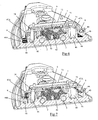
- the figure 6 illustrates the path of the steam produced by the main vaporization chamber 42 in the iron thus produced during an active ironing phase, that is to say when the iron rests horizontally on its sole 2.
- the steam produced by the main vaporization chamber 42 escapes vertically through the steam outlet opening 70 equipped with the first filtering grid 8 so that the particles of scale greater than 1 mm diameter transported by the steam are stopped by the first filtering grid 8 and fall, by gravity, into the main vaporization chamber 42.
- the filtered vapor that has passed through the first filtration grid 8 then flows horizontally into the steam distribution channel 71, then vertically through the lateral openings 74 to reach the intermediate chamber 46 of the foundry 40 in which the possible drops of The vapor-transported water is vaporized, the superheated vapor escaping thereafter through the indentations 47A of the partition walls 47 to lateral channels 44 of the steam distribution circuit.
- the vapor present in the side channels 44 then flows through the second filtration grid 9 and vertically in the holes 44A through the foundry 40 before being diffused through the steam outlet holes 20 of the sole.
- any scale particles transported by the steam having a diameter of greater than 0.4 mm are stopped upstream of the second filtration grid 9 so that these particles of scale, having a diameter included between 0.4 and 1 mm, are stored in the part of the vapor circuit extending between the first filtration grid 8 and the second filtration grid 9.
- the orientation of the first and second filtration grids 8, 9 parallel to the longitudinal direction of the sole 2 has the advantage of preventing the particles of scale retained upstream of these filtration grids 8, 9 from agglomerate on these filtration grids 8.9 when the iron 1 rests on its heel 32, especially during inactive ironing or storage of the iron 1.
- Such a characteristic thus makes it possible to avoid a rapid obstruction of the filtering grids 8, 9 and thus makes it possible to increase the service life of the iron.
- the scale particles retained upstream of the first filtration grid 8 fall into the rear part 42A of the main vaporization chamber 42 when the iron 1 is placed on its heel 32, so that this rear portion 42A of the vaporization chamber 42 serves as a storage area where the scale particles come to agglomerate gradually over time without disturbing the operation of the iron.
- the scale particles which are retained upstream of the second filtering grid 9 are stored stored at the rear ends 44B of the side channels 44 when the iron 1 is placed on its heel 32, which allows the avoid rapid clogging of the second filter grid 9.
- the non-stick coating of the filtration grids prevents the scale from sticking to the filter grid and closes the filtration grid too quickly.
- the low effusivity of the material used for the filtration grid, such as the glass fabric also has the advantage of avoiding significant evaporation of water drops coming into contact with the first superheated filtration grid, which also allows to limit the formation of scale on the filtration grid.
- This filtration device therefore solves the problem of discharging large particles of scale which stain the linen during ironing and which is perceived very unfavorably by the user, the rejection by the sole of scale particles to a maximum of maximum size of 0.6 mm in diameter was substantially invisible and considered acceptable by the user.
- the second filtration grid 9 can be fixed on the closure plate 7 and be positioned in the upper part of the side channels 44 of the steam distribution circuit.
- Such an alternative embodiment has the advantage of facilitating the assembly of the heating body, the first and second filtering grids 8, 9 being positionable on the closure plate 7 in a step prior to assembly of the closure plate on the foundry.
- the first filtering grid may be fixed on the closure plate at each of the lateral openings of the steam distribution channel, such an embodiment having the advantage of moving the first filtration grid of the main vaporization chamber so that the probability that a droplet of unvaporized water reaches the first filtration grid is reduced.
- the iron according to the invention may have only one filtration grid disposed on the steam distribution circuit, this filtration grid having openings between 0.2 mm and 0.6 mm.
- the apparatus may comprise a third filtering grid disposed on the steam distribution circuit, downstream of the first and second filtering grids, this third filtering grid having smaller openings. larger than those of the openings of the first and second filtration grids.
- the openings of the third filter grid will measure between 0.1 mm and 0.3 mm side, so that the particles that can pass through the third grid are invisible to the naked eye.
Landscapes
- Engineering & Computer Science (AREA)
- Textile Engineering (AREA)
- Irons (AREA)
- Filtering Materials (AREA)
Claims (12)
- Bügeleisen (1) mit einer Bügelsohle (2), über der ein Gehäuse (3) angeordnet ist, das ein hinteres Ende umfasst, welches eine Standfläche (32) aufweist, auf der das Bügeleisen (1) während der Bügelpausen im Wesentlichen senkrecht abgestellt werden kann, und mit einem Dampfkreislauf, der mindestens ein Filtergitter (8, 9) umfasst, in dem Kalkpartikel zurückgehalten werden sollen, dadurch gekennzeichnet, dass dieses Filtergitter (8, 9) parallel zur Längsrichtung der Sohle (2) verläuft und derart im Dampfkreislauf angeordnet ist, dass es von unten nach oben von dem Dampf durchströmt wird, wenn das Bügeleisen horizontal auf der Sohle (2) aufliegt.
- Bügeleisen (1) nach Anspruch 1, dadurch gekennzeichnet, dass das Filtergitter (8) eben ist.
- Bügeleisen (1) nach Anspruch 2, dadurch gekennzeichnet, dass das Filtergitter parallel zur Ebene der Sohle liegt.
- Bügeleisen (1) nach einem der Ansprüche 1 bis 3, dadurch gekennzeichnet, dass das Filtergitter (9) Maschen mit einer Breite von 0,2 mm bis 0,6 mm aufweist.
- Bügeleisen (1) nach einem der Ansprüche 1 bis 4, dadurch gekennzeichnet, dass die Sohle (2) sich in Wärmekontakt mit einem Heizkörper (4) befindet und Dampfaustrittslöcher (20) aufweist, denen über den Dampfkreislauf Dampf zugeführt wird.
- Bügeleisen nach Anspruch 5, dadurch gekennzeichnet, dass der Heizkörper (4) ein Gussteil (40) umfasst, das eine Innenseite aufweist, die sich in Wärmekontakt mit der Sohle (2) befindet, sowie eine Verdampfungskammer (42), die durch eine Verschlussplatte (7) abgeschlossen wird, welche an der Oberseite des Gussteils (40) aufgesteckt ist, wobei die Verdampfungskammer (42) über eine in der Verschlussplatte (7) eingelassene Dampfauslassöffnung (70) mit dem Dampfkreislauf verbunden ist, und dadurch gekennzeichnet, dass das Filtergitter (8) auf Höhe dieser Dampfauslassöffnung (70) angeordnet ist.
- Bügeleisen nach einem der Ansprüche 1 bis 6, dadurch gekennzeichnet, dass der Dampfkreislauf ein erstes Filtergitter (8) und ein zweites Filtergitter (9) umfasst, die dem Strömungsverlauf des Dampfes folgend nacheinander angeordnet sind, wobei sich das zweite Filtergitter (9) unterhalb des ersten Filtergitters (8) befindet und Durchlässe aufweist, die kleiner sind als die Durchlässe des ersten Filtergitters (8).
- Bügeleisen (1) nach Anspruch 7, dadurch gekennzeichnet, dass die Durchlässe des ersten Filtergitters (8) eine Seitenlänge zwischen 1 mm und 2 mm aufweisen und dass die Durchlässe des zweiten Filtergitters (9) eine Seitenlänge zwischen 0,2 und 0,6 mm aufweisen.
- Bügeleisen (1) nach einem der Ansprüche 6 bis 8, dadurch gekennzeichnet, dass die genannte Dampfauslassöffnung (70) in einen Dampfverteilungskanal (71) mündet, welcher mit einer im Gussteil (40) angeordneten Dampfleitung (44) verbunden ist, wobei diese Leitung (44) Öffnungen (44A) aufweist, die das Gussteil (40) durchsetzen und letztendlich in einen Hohlraum zur Dampfverteilung münden, über den den Dampfaustrittslöchern (20) der Sohle (2) Dampf zugeführt wird, und dadurch gekennzeichnet, dass das zweite Filtergitter (9) in der seitlichen Leitung (44) vor den das Gussteil (40) durchsetzenden Öffnungen (44A) angeordnet ist.
- Bügeleisen (1) nach einem der Ansprüche 1 bis 9, dadurch gekennzeichnet, dass das Filtergitter (8, 9) mit einer Antihaftbeschichtung überzogen ist.
- Bügelvorrichtung (1) nach Anspruch 10, dadurch gekennzeichnet, dass diese Beschichtung aus einem Fluorpolymer-Material hergestellt ist.
- Bügelvorrichtung (1) nach Anspruch 11, dadurch gekennzeichnet, dass das erste Filtergitter und/oder das zweite Filtergitter aus Edelstahl oder aus PTFEbeschichtetem Glasgewebe hergestellt ist.
Applications Claiming Priority (1)
| Application Number | Priority Date | Filing Date | Title |
|---|---|---|---|
| FR1158009A FR2979923B1 (fr) | 2011-09-09 | 2011-09-09 | Fer a repasser comportant un circuit de distribution de vapeur comprenant une grille de filtration |
Publications (2)
| Publication Number | Publication Date |
|---|---|
| EP2578745A1 EP2578745A1 (de) | 2013-04-10 |
| EP2578745B1 true EP2578745B1 (de) | 2015-04-22 |
Family
ID=46758691
Family Applications (1)
| Application Number | Title | Priority Date | Filing Date |
|---|---|---|---|
| EP20120183393 Active EP2578745B1 (de) | 2011-09-09 | 2012-09-06 | Bügeleisen, das einen Dampfverteilungskreislauf mit einem Filtergitter umfasst |
Country Status (4)
| Country | Link |
|---|---|
| EP (1) | EP2578745B1 (de) |
| CN (1) | CN102995372B (de) |
| FR (1) | FR2979923B1 (de) |
| RU (1) | RU2607171C2 (de) |
Families Citing this family (1)
| Publication number | Priority date | Publication date | Assignee | Title |
|---|---|---|---|---|
| FR3060031B1 (fr) * | 2016-12-13 | 2019-12-13 | Seb S.A. | Fer a vapeur comportant un circuit de distribution de vapeur menage dans un corps en contact thermique avec une surface de repassage |
Family Cites Families (6)
| Publication number | Priority date | Publication date | Assignee | Title |
|---|---|---|---|---|
| DE3006783A1 (de) * | 1980-02-22 | 1981-08-27 | Ritter Aluminium Gmbh, 7300 Esslingen | Buegeleisensohle fuer ein dampf-buegeleisen |
| DE3743917A1 (de) * | 1987-12-23 | 1989-07-06 | Bosch Siemens Hausgeraete | Dampfbuegeleisen |
| FR2696197B1 (fr) * | 1992-09-29 | 1994-11-25 | Seb Sa | Fer à repasser à chambre de vaporisation pourvue d'une grille de répartition d'eau. |
| DE10014815A1 (de) * | 2000-03-27 | 2001-10-11 | Rowenta Werke Gmbh | Physikochemische Kesselsteinverhütungsvorrichtung mit einem flockenverhindernden Gitter für Dampfbügeleisen |
| CN2795266Y (zh) * | 2004-08-23 | 2006-07-12 | 佛山市三水区域桥电器有限公司 | 一种蒸气熨烫机的蒸气发生装置 |
| CN201826184U (zh) * | 2010-10-22 | 2011-05-11 | 上海市第一中学 | 新型电熨斗 |
-
2011
- 2011-09-09 FR FR1158009A patent/FR2979923B1/fr not_active Expired - Fee Related
-
2012
- 2012-09-04 RU RU2012137537A patent/RU2607171C2/ru active
- 2012-09-05 CN CN201210326339.1A patent/CN102995372B/zh active Active
- 2012-09-06 EP EP20120183393 patent/EP2578745B1/de active Active
Also Published As
| Publication number | Publication date |
|---|---|
| RU2012137537A (ru) | 2014-03-10 |
| RU2607171C2 (ru) | 2017-01-10 |
| FR2979923B1 (fr) | 2015-01-09 |
| FR2979923A1 (fr) | 2013-03-15 |
| CN102995372A (zh) | 2013-03-27 |
| CN102995372B (zh) | 2016-04-13 |
| EP2578745A1 (de) | 2013-04-10 |
Similar Documents
| Publication | Publication Date | Title |
|---|---|---|
| EP2578743B1 (de) | Elektrohaushaltsgerät, das einen Dampfverteilungskreis umfasst | |
| EP2845944B1 (de) | Elektrohaushaltsgerät zum Bügeln, das einen Filter zum Zurückhalten der mit dem Dampf transportierten Kalkpartikel umfasst | |
| EP3555359B1 (de) | Dampfbügelvorrichtung | |
| EP3064640B1 (de) | Elektrohaushaltsgerät zum bügeln, das einen behälter umfasst, der einen wasserenthärter und einen dampfverteilungskreislauf mit einem filter umfasst | |
| EP2578742B1 (de) | Bügelgerät, das einen Dampfverteilungskreislauf umfasst | |
| EP3064639B1 (de) | Elektrohaushaltsgerät zum bügeln, das einen filter zum zurückhalten der mit dem dampf transportierten kalkpartikel umfasst | |
| EP3580385B1 (de) | Bügeleisen mit einer vorrichtung zum rückhalten von durch dampf transportierten kalkpartikeln | |
| EP3362598B1 (de) | Bügeleisen, das eine dampferzeugungskammer umfasst, die mit zwei verschiedenen verdampfungszonen versehen ist | |
| EP3505676B1 (de) | Bügelgerät, das eine dampfabzweigleitung umfasst | |
| FR3072100A1 (fr) | Appareil de defroissage equipe d'une chambre de vaporisation munie d'un orifice de nettoyage | |
| EP2578745B1 (de) | Bügeleisen, das einen Dampfverteilungskreislauf mit einem Filtergitter umfasst | |
| EP3336240A1 (de) | Bügeleisen, das eine rückhalte- und verdampfungsvorrichtung von kondensaten umfasst | |
| EP3336245B1 (de) | Dampfbügelgerät, das eine dampferzeugende basis und ein bügeleisen umfasst, die über eine leitung miteinander verbunden sind | |
| EP3336244B1 (de) | Bügeleisen, das eine bügelfläche, eine heizsohle und eine dampfkammer besitzt | |
| EP3336241B1 (de) | Bügelgerät mit dampfbügeleisen, das einen dampfverteilungskreislauf in einem körper umfasst, der in thermischem kontakt mit einer bügelfläche ist | |
| EP3757279B1 (de) | Bügeleisen, das eine rückhaltevorrichtung für die durch den dampf transportierten kalkpartikel umfasst | |
| FR2940981A1 (fr) | Fer a repasser a vapeur comportant un corps chauffant muni d'un insert | |
| EP4299825A1 (de) | Elektrisches haushaltsgerät zum bügeln und/oder glätten mit einer vorrichtung zum zurückhalten von dampfgetragenen kalkpartikeln |
Legal Events
| Date | Code | Title | Description |
|---|---|---|---|
| PUAI | Public reference made under article 153(3) epc to a published international application that has entered the european phase |
Free format text: ORIGINAL CODE: 0009012 |
|
| AK | Designated contracting states |
Kind code of ref document: A1 Designated state(s): AL AT BE BG CH CY CZ DE DK EE ES FI FR GB GR HR HU IE IS IT LI LT LU LV MC MK MT NL NO PL PT RO RS SE SI SK SM TR |
|
| AX | Request for extension of the european patent |
Extension state: BA ME |
|
| 17P | Request for examination filed |
Effective date: 20130910 |
|
| RBV | Designated contracting states (corrected) |
Designated state(s): AL AT BE BG CH CY CZ DE DK EE ES FI FR GB GR HR HU IE IS IT LI LT LU LV MC MK MT NL NO PL PT RO RS SE SI SK SM TR |
|
| GRAP | Despatch of communication of intention to grant a patent |
Free format text: ORIGINAL CODE: EPIDOSNIGR1 |
|
| INTG | Intention to grant announced |
Effective date: 20150205 |
|
| GRAS | Grant fee paid |
Free format text: ORIGINAL CODE: EPIDOSNIGR3 |
|
| GRAA | (expected) grant |
Free format text: ORIGINAL CODE: 0009210 |
|
| AK | Designated contracting states |
Kind code of ref document: B1 Designated state(s): AL AT BE BG CH CY CZ DE DK EE ES FI FR GB GR HR HU IE IS IT LI LT LU LV MC MK MT NL NO PL PT RO RS SE SI SK SM TR |
|
| REG | Reference to a national code |
Ref country code: GB Ref legal event code: FG4D Free format text: NOT ENGLISH |
|
| REG | Reference to a national code |
Ref country code: CH Ref legal event code: EP |
|
| REG | Reference to a national code |
Ref country code: AT Ref legal event code: REF Ref document number: 723310 Country of ref document: AT Kind code of ref document: T Effective date: 20150515 |
|
| REG | Reference to a national code |
Ref country code: IE Ref legal event code: FG4D Free format text: LANGUAGE OF EP DOCUMENT: FRENCH |
|
| REG | Reference to a national code |
Ref country code: DE Ref legal event code: R096 Ref document number: 602012006829 Country of ref document: DE Effective date: 20150603 |
|
| REG | Reference to a national code |
Ref country code: NL Ref legal event code: VDEP Effective date: 20150422 |
|
| REG | Reference to a national code |
Ref country code: AT Ref legal event code: MK05 Ref document number: 723310 Country of ref document: AT Kind code of ref document: T Effective date: 20150422 |
|
| REG | Reference to a national code |
Ref country code: LT Ref legal event code: MG4D |
|
| PG25 | Lapsed in a contracting state [announced via postgrant information from national office to epo] |
Ref country code: NL Free format text: LAPSE BECAUSE OF FAILURE TO SUBMIT A TRANSLATION OF THE DESCRIPTION OR TO PAY THE FEE WITHIN THE PRESCRIBED TIME-LIMIT Effective date: 20150422 |
|
| REG | Reference to a national code |
Ref country code: FR Ref legal event code: PLFP Year of fee payment: 4 |
|
| PG25 | Lapsed in a contracting state [announced via postgrant information from national office to epo] |
Ref country code: NO Free format text: LAPSE BECAUSE OF FAILURE TO SUBMIT A TRANSLATION OF THE DESCRIPTION OR TO PAY THE FEE WITHIN THE PRESCRIBED TIME-LIMIT Effective date: 20150722 Ref country code: ES Free format text: LAPSE BECAUSE OF FAILURE TO SUBMIT A TRANSLATION OF THE DESCRIPTION OR TO PAY THE FEE WITHIN THE PRESCRIBED TIME-LIMIT Effective date: 20150422 Ref country code: LT Free format text: LAPSE BECAUSE OF FAILURE TO SUBMIT A TRANSLATION OF THE DESCRIPTION OR TO PAY THE FEE WITHIN THE PRESCRIBED TIME-LIMIT Effective date: 20150422 Ref country code: PT Free format text: LAPSE BECAUSE OF FAILURE TO SUBMIT A TRANSLATION OF THE DESCRIPTION OR TO PAY THE FEE WITHIN THE PRESCRIBED TIME-LIMIT Effective date: 20150824 Ref country code: HR Free format text: LAPSE BECAUSE OF FAILURE TO SUBMIT A TRANSLATION OF THE DESCRIPTION OR TO PAY THE FEE WITHIN THE PRESCRIBED TIME-LIMIT Effective date: 20150422 Ref country code: FI Free format text: LAPSE BECAUSE OF FAILURE TO SUBMIT A TRANSLATION OF THE DESCRIPTION OR TO PAY THE FEE WITHIN THE PRESCRIBED TIME-LIMIT Effective date: 20150422 |
|
| PG25 | Lapsed in a contracting state [announced via postgrant information from national office to epo] |
Ref country code: LV Free format text: LAPSE BECAUSE OF FAILURE TO SUBMIT A TRANSLATION OF THE DESCRIPTION OR TO PAY THE FEE WITHIN THE PRESCRIBED TIME-LIMIT Effective date: 20150422 Ref country code: RS Free format text: LAPSE BECAUSE OF FAILURE TO SUBMIT A TRANSLATION OF THE DESCRIPTION OR TO PAY THE FEE WITHIN THE PRESCRIBED TIME-LIMIT Effective date: 20150422 Ref country code: AT Free format text: LAPSE BECAUSE OF FAILURE TO SUBMIT A TRANSLATION OF THE DESCRIPTION OR TO PAY THE FEE WITHIN THE PRESCRIBED TIME-LIMIT Effective date: 20150422 Ref country code: IS Free format text: LAPSE BECAUSE OF FAILURE TO SUBMIT A TRANSLATION OF THE DESCRIPTION OR TO PAY THE FEE WITHIN THE PRESCRIBED TIME-LIMIT Effective date: 20150822 Ref country code: GR Free format text: LAPSE BECAUSE OF FAILURE TO SUBMIT A TRANSLATION OF THE DESCRIPTION OR TO PAY THE FEE WITHIN THE PRESCRIBED TIME-LIMIT Effective date: 20150723 |
|
| REG | Reference to a national code |
Ref country code: DE Ref legal event code: R097 Ref document number: 602012006829 Country of ref document: DE |
|
| PG25 | Lapsed in a contracting state [announced via postgrant information from national office to epo] |
Ref country code: DK Free format text: LAPSE BECAUSE OF FAILURE TO SUBMIT A TRANSLATION OF THE DESCRIPTION OR TO PAY THE FEE WITHIN THE PRESCRIBED TIME-LIMIT Effective date: 20150422 Ref country code: EE Free format text: LAPSE BECAUSE OF FAILURE TO SUBMIT A TRANSLATION OF THE DESCRIPTION OR TO PAY THE FEE WITHIN THE PRESCRIBED TIME-LIMIT Effective date: 20150422 |
|
| PLBE | No opposition filed within time limit |
Free format text: ORIGINAL CODE: 0009261 |
|
| STAA | Information on the status of an ep patent application or granted ep patent |
Free format text: STATUS: NO OPPOSITION FILED WITHIN TIME LIMIT |
|
| PG25 | Lapsed in a contracting state [announced via postgrant information from national office to epo] |
Ref country code: CZ Free format text: LAPSE BECAUSE OF FAILURE TO SUBMIT A TRANSLATION OF THE DESCRIPTION OR TO PAY THE FEE WITHIN THE PRESCRIBED TIME-LIMIT Effective date: 20150422 Ref country code: SK Free format text: LAPSE BECAUSE OF FAILURE TO SUBMIT A TRANSLATION OF THE DESCRIPTION OR TO PAY THE FEE WITHIN THE PRESCRIBED TIME-LIMIT Effective date: 20150422 Ref country code: RO Free format text: LAPSE BECAUSE OF NON-PAYMENT OF DUE FEES Effective date: 20150422 Ref country code: PL Free format text: LAPSE BECAUSE OF FAILURE TO SUBMIT A TRANSLATION OF THE DESCRIPTION OR TO PAY THE FEE WITHIN THE PRESCRIBED TIME-LIMIT Effective date: 20150422 |
|
| 26N | No opposition filed |
Effective date: 20160125 |
|
| PG25 | Lapsed in a contracting state [announced via postgrant information from national office to epo] |
Ref country code: IT Free format text: LAPSE BECAUSE OF FAILURE TO SUBMIT A TRANSLATION OF THE DESCRIPTION OR TO PAY THE FEE WITHIN THE PRESCRIBED TIME-LIMIT Effective date: 20150422 Ref country code: MC Free format text: LAPSE BECAUSE OF FAILURE TO SUBMIT A TRANSLATION OF THE DESCRIPTION OR TO PAY THE FEE WITHIN THE PRESCRIBED TIME-LIMIT Effective date: 20150422 Ref country code: LU Free format text: LAPSE BECAUSE OF FAILURE TO SUBMIT A TRANSLATION OF THE DESCRIPTION OR TO PAY THE FEE WITHIN THE PRESCRIBED TIME-LIMIT Effective date: 20150906 |
|
| REG | Reference to a national code |
Ref country code: CH Ref legal event code: PL |
|
| PG25 | Lapsed in a contracting state [announced via postgrant information from national office to epo] |
Ref country code: SI Free format text: LAPSE BECAUSE OF FAILURE TO SUBMIT A TRANSLATION OF THE DESCRIPTION OR TO PAY THE FEE WITHIN THE PRESCRIBED TIME-LIMIT Effective date: 20150422 |
|
| REG | Reference to a national code |
Ref country code: IE Ref legal event code: MM4A |
|
| PG25 | Lapsed in a contracting state [announced via postgrant information from national office to epo] |
Ref country code: LI Free format text: LAPSE BECAUSE OF NON-PAYMENT OF DUE FEES Effective date: 20150930 Ref country code: IE Free format text: LAPSE BECAUSE OF NON-PAYMENT OF DUE FEES Effective date: 20150906 Ref country code: CH Free format text: LAPSE BECAUSE OF NON-PAYMENT OF DUE FEES Effective date: 20150930 |
|
| REG | Reference to a national code |
Ref country code: FR Ref legal event code: PLFP Year of fee payment: 5 |
|
| PG25 | Lapsed in a contracting state [announced via postgrant information from national office to epo] |
Ref country code: MT Free format text: LAPSE BECAUSE OF FAILURE TO SUBMIT A TRANSLATION OF THE DESCRIPTION OR TO PAY THE FEE WITHIN THE PRESCRIBED TIME-LIMIT Effective date: 20150422 |
|
| PG25 | Lapsed in a contracting state [announced via postgrant information from national office to epo] |
Ref country code: SM Free format text: LAPSE BECAUSE OF FAILURE TO SUBMIT A TRANSLATION OF THE DESCRIPTION OR TO PAY THE FEE WITHIN THE PRESCRIBED TIME-LIMIT Effective date: 20150422 Ref country code: HU Free format text: LAPSE BECAUSE OF FAILURE TO SUBMIT A TRANSLATION OF THE DESCRIPTION OR TO PAY THE FEE WITHIN THE PRESCRIBED TIME-LIMIT; INVALID AB INITIO Effective date: 20120906 Ref country code: BG Free format text: LAPSE BECAUSE OF FAILURE TO SUBMIT A TRANSLATION OF THE DESCRIPTION OR TO PAY THE FEE WITHIN THE PRESCRIBED TIME-LIMIT Effective date: 20150422 |
|
| REG | Reference to a national code |
Ref country code: FR Ref legal event code: CA Effective date: 20170518 |
|
| PG25 | Lapsed in a contracting state [announced via postgrant information from national office to epo] |
Ref country code: SE Free format text: LAPSE BECAUSE OF FAILURE TO SUBMIT A TRANSLATION OF THE DESCRIPTION OR TO PAY THE FEE WITHIN THE PRESCRIBED TIME-LIMIT Effective date: 20150422 Ref country code: CY Free format text: LAPSE BECAUSE OF FAILURE TO SUBMIT A TRANSLATION OF THE DESCRIPTION OR TO PAY THE FEE WITHIN THE PRESCRIBED TIME-LIMIT Effective date: 20150422 |
|
| REG | Reference to a national code |
Ref country code: FR Ref legal event code: PLFP Year of fee payment: 6 |
|
| PG25 | Lapsed in a contracting state [announced via postgrant information from national office to epo] |
Ref country code: MK Free format text: LAPSE BECAUSE OF FAILURE TO SUBMIT A TRANSLATION OF THE DESCRIPTION OR TO PAY THE FEE WITHIN THE PRESCRIBED TIME-LIMIT Effective date: 20150422 |
|
| REG | Reference to a national code |
Ref country code: FR Ref legal event code: PLFP Year of fee payment: 7 |
|
| PG25 | Lapsed in a contracting state [announced via postgrant information from national office to epo] |
Ref country code: AL Free format text: LAPSE BECAUSE OF FAILURE TO SUBMIT A TRANSLATION OF THE DESCRIPTION OR TO PAY THE FEE WITHIN THE PRESCRIBED TIME-LIMIT Effective date: 20150422 |
|
| PGFP | Annual fee paid to national office [announced via postgrant information from national office to epo] |
Ref country code: TR Payment date: 20230822 Year of fee payment: 12 Ref country code: GB Payment date: 20230920 Year of fee payment: 12 |
|
| PGFP | Annual fee paid to national office [announced via postgrant information from national office to epo] |
Ref country code: FR Payment date: 20230927 Year of fee payment: 12 Ref country code: DE Payment date: 20230911 Year of fee payment: 12 Ref country code: BE Payment date: 20230914 Year of fee payment: 12 |