EP3336244B1 - Bügeleisen, das eine bügelfläche, eine heizsohle und eine dampfkammer besitzt - Google Patents
Bügeleisen, das eine bügelfläche, eine heizsohle und eine dampfkammer besitzt Download PDFInfo
- Publication number
- EP3336244B1 EP3336244B1 EP17206032.9A EP17206032A EP3336244B1 EP 3336244 B1 EP3336244 B1 EP 3336244B1 EP 17206032 A EP17206032 A EP 17206032A EP 3336244 B1 EP3336244 B1 EP 3336244B1
- Authority
- EP
- European Patent Office
- Prior art keywords
- iron
- heating
- ironing surface
- steam
- zone
- Prior art date
- Legal status (The legal status is an assumption and is not a legal conclusion. Google has not performed a legal analysis and makes no representation as to the accuracy of the status listed.)
- Active
Links
Images


Classifications
-
- D—TEXTILES; PAPER
- D06—TREATMENT OF TEXTILES OR THE LIKE; LAUNDERING; FLEXIBLE MATERIALS NOT OTHERWISE PROVIDED FOR
- D06F—LAUNDERING, DRYING, IRONING, PRESSING OR FOLDING TEXTILE ARTICLES
- D06F75/00—Hand irons
- D06F75/08—Hand irons internally heated by electricity
- D06F75/10—Hand irons internally heated by electricity with means for supplying steam to the article being ironed
- D06F75/14—Hand irons internally heated by electricity with means for supplying steam to the article being ironed the steam being produced from water in a reservoir carried by the iron
- D06F75/16—Hand irons internally heated by electricity with means for supplying steam to the article being ironed the steam being produced from water in a reservoir carried by the iron the reservoir being heated to produce the steam
-
- D—TEXTILES; PAPER
- D06—TREATMENT OF TEXTILES OR THE LIKE; LAUNDERING; FLEXIBLE MATERIALS NOT OTHERWISE PROVIDED FOR
- D06F—LAUNDERING, DRYING, IRONING, PRESSING OR FOLDING TEXTILE ARTICLES
- D06F75/00—Hand irons
- D06F75/08—Hand irons internally heated by electricity
- D06F75/24—Arrangements of the heating means within the iron; Arrangements for distributing, conducting or storing the heat
-
- D—TEXTILES; PAPER
- D06—TREATMENT OF TEXTILES OR THE LIKE; LAUNDERING; FLEXIBLE MATERIALS NOT OTHERWISE PROVIDED FOR
- D06F—LAUNDERING, DRYING, IRONING, PRESSING OR FOLDING TEXTILE ARTICLES
- D06F75/00—Hand irons
- D06F75/08—Hand irons internally heated by electricity
- D06F75/10—Hand irons internally heated by electricity with means for supplying steam to the article being ironed
- D06F75/20—Arrangements for discharging the steam to the article being ironed
-
- D—TEXTILES; PAPER
- D06—TREATMENT OF TEXTILES OR THE LIKE; LAUNDERING; FLEXIBLE MATERIALS NOT OTHERWISE PROVIDED FOR
- D06F—LAUNDERING, DRYING, IRONING, PRESSING OR FOLDING TEXTILE ARTICLES
- D06F75/00—Hand irons
- D06F75/08—Hand irons internally heated by electricity
- D06F75/24—Arrangements of the heating means within the iron; Arrangements for distributing, conducting or storing the heat
- D06F75/243—Arrangements of the heating means within the iron; Arrangements for distributing, conducting or storing the heat using other than ohmic-resistance heating means, e.g. electrolytic or induction heating
-
- D—TEXTILES; PAPER
- D06—TREATMENT OF TEXTILES OR THE LIKE; LAUNDERING; FLEXIBLE MATERIALS NOT OTHERWISE PROVIDED FOR
- D06F—LAUNDERING, DRYING, IRONING, PRESSING OR FOLDING TEXTILE ARTICLES
- D06F75/00—Hand irons
- D06F75/08—Hand irons internally heated by electricity
- D06F75/26—Temperature control or indicating arrangements
-
- D—TEXTILES; PAPER
- D06—TREATMENT OF TEXTILES OR THE LIKE; LAUNDERING; FLEXIBLE MATERIALS NOT OTHERWISE PROVIDED FOR
- D06F—LAUNDERING, DRYING, IRONING, PRESSING OR FOLDING TEXTILE ARTICLES
- D06F75/00—Hand irons
- D06F75/38—Sole plates
Definitions
- the present invention relates to an iron comprising an ironing surface, a heating sole intended to heat the ironing surface and a vaporization chamber, the heating sole comprising a first electrical resistance arranged directly above a so-called zone. hot ironing surface and the vaporization chamber being provided in a heating body comprising a second electrical resistance.
- the present invention relates more particularly to an iron in which the heating body is placed in line with a so-called cold zone of the ironing surface comprising steam outlet holes, the steam outlet holes being fed. by a vapor diffusion chamber formed in a cavity formed between the vaporization chamber and the cold zone of the ironing surface.
- an aim of the present invention is to remedy these drawbacks by offering an iron that is simple and economical to use.
- Another object of the present invention is to provide an iron with improved ironing performance.
- the invention relates to an iron comprising an ironing surface, a heating sole intended to heat the ironing surface and a vaporization chamber, the heating sole comprising a first electrical resistance arranged in line with 'a so-called hot zone of the ironing surface, the vaporization chamber being provided in a heating body comprising a second electrical resistance, the vaporization chamber being arranged directly above a so-called cold zone of the ironing surface comprising steam outlet holes, the steam outlet holes being supplied by a diffusion chamber of steam provided outside the vaporization chamber, in a cavity formed between the vaporization chamber and the cold zone of the ironing surface, characterized in that the heating body and the heating sole are made in two separate parts and in that the heating body is attached to the heating sole.
- the term "arranged directly above the zone” is understood to mean that the member is placed above the zone when the iron rests horizontally on the ironing surface.
- the device thus produced has the advantage of having a vaporization chamber arranged in a separate room from the heating sole, which makes it possible to reduce the heat exchange between the heating body and the vaporization chamber and to control the temperature more easily. of the vaporization chamber regardless of the temperature of the heating pad.
- such a construction makes it possible to obtain a strong thermal gradient between the cold zone of the ironing surface used to diffuse the steam and the hot zone used to dry the laundry, the heating body comprising the vaporization chamber being able to remain at low temperature. (around 100 ° C) when the hot zone of the sole is around 200 ° C.
- the fact that the heating body is placed on the heating soleplate makes it possible to use the heating sole as the sole reference point for the support of the ironing surface.
- the hot zone corresponds to the smallest closed convex surface in which the orthogonal projection of the first electrical resistance is inscribed.
- the heating sole and the heating body are not in contact with one another in the zone situated directly above the cold zone of the ironing surface.
- the heating soleplate and the heating body are in contact with one another only at the level of contact surfaces, which according to an orthogonal projection on the ironing surface, are distributed around the periphery of the cold zone of so as to establish a controlled thermal gradient between the cold zone and the heating sole.
- the ironing surface is carried by a cap which is attached under the face of the heating soleplate and the heating sole comprises, facing the cold zone, an opening which is at least partially masked by the cover, the heating body extending above the opening.
- Such a characteristic allows the vapor coming from the vaporization chamber to be diffused towards the vapor outlet holes present in the cold zone without circulating on the heating soleplate but remaining in the environment of the cold ironing zone. This prevents overheating of the steam as it travels from the vaporization chamber to the steam outlet holes of the cold zone as well as excessive heating of the cold zone of the cap by the heating sole. Very good ironing performance is thus obtained, the cold zone of the ironing surface, which includes outlet holes through which the steam is diffused, favoring the condensation of the steam in the laundry and allowing its good humidification before it is dried by the hot zone.
- the cap is made from a sheet of aluminum or steel.
- the ironing surface is formed by a lower face of the heating sole and the heating sole has, at the level of the cold zone, a part where its thickness is reduced compared to its opposite thickness. of the hot zone.
- the steam diffusion chamber is located outside the volume swept by the hot zone of the ironing surface when the latter is moved in a plane perpendicular to the ironing surface.
- Such a construction makes it possible to move the vapor diffusion chamber away from the environment overheated by the heating sole.
- the first electrical resistance is a U-shaped shielded resistor and the vapor diffusion chamber is located outside the volume swept by the resistor when it is moved in a plane perpendicular to the resistor. the ironing surface.
- the power supply to the first electrical resistance is regulated by means of a first thermostat.
- the first thermostat comprises a setpoint or trigger temperature which is between 90 ° C and 240 ° C.
- Such a characteristic makes it possible to obtain a hot zone, the temperature of which can be adapted as a function of the textile to be ironed.
- the setpoint temperature of the first thermostat is adjustable by the user.
- the power supply to the second electrical resistance is regulated by means of a second thermostat, the set point or trigger temperature of which is between 100 ° C and 135 ° C.
- Such a characteristic makes it possible to obtain a vapor with a high humidity rate at the outlet of the vaporization chamber for better ironing performance.
- the setpoint temperature of the second thermostat is not adjustable by the user.
- the setpoint temperature of the second thermostat is automatically adjusted by a control unit according to the setpoint temperature of the first thermostat or according to the measurement of the temperature of the heating soleplate.
- Such a characteristic makes it possible to automatically increase the setpoint temperature of the second thermostat when the temperature of the heating soleplate decreases below a predetermined threshold.
- the cold zone is placed on the front half of the ironing surface and the hot zone is placed on the rear half of the ironing surface.
- Such a feature makes it possible, when the iron is moved forwards, to first humidify the textile to be ironed using humid steam through the cold zone of the sole, then to dry the fabric with the hot area.
- the steam outlet holes from the cold zone are distributed over the ironing surface over a width representing at least 40% of the maximum width of the ironing surface and preferably more than 65% of this width.
- Such a characteristic makes it possible to have a large part of the ironing surface which contributes to humidifying the laundry, when the iron is moved from rear to front, for greater ironing efficiency.
- the steam outlet holes are distributed over the ironing surface over a length representing at least 40% of the total length of the ironing surface.
- Such a characteristic makes it possible to have a large part of the ironing surface which contributes to humidifying the laundry, when the iron is moved sideways, for greater ironing efficiency.
- the hot zone of the ironing surface has steam outlet holes.
- Such a feature makes it possible to improve the ironing performance when the iron is moved back and forth.
- the heating body is coupled mechanically to the sole by fixing points arranged at the edge of the cavity forming the diffusion chamber.
- the heating body rests on the edge of the opening, a seal being advantageously arranged between the heating body and the heating sole.
- Such a characteristic makes it possible both to limit the heat transfer between the heating body and the heating soleplate and to ensure that the diffusion chamber is sealed.
- the opening, or the thinner part of the heating soleplate extends in width over more than 40% of the width of the ironing surface and preferably over more than 65%. the width of the ironing surface.
- width of the ironing surface is meant the width of the ironing surface at the height of the opening.
- the opening extends in width over more than 40% of the maximum width of the ironing surface and preferably over more than 65% of the maximum width of the ironing surface.
- maximum width is meant the overall width of the ironing surface.
- the apparatus comprises a manifold positioned in the diffusion chamber, the manifold comprising an orifice facing each of the vapor outlet holes of the cold zone of the ironing surface.
- Such a characteristic makes it possible to pre-orient the steam flow in the direction of the steam outlet holes of the cold zone of the ironing surface in order to limit the heat exchanges being established between the steam flow and the heating soleplate.
- the collector is fixed to the body heating.
- the collector is made from a sheet of stainless steel or an aluminum alloy.
- the heating body and / or the heating soleplate are produced in an aluminum foundry.
- the vaporization chamber comprises a device for separating the condensates from the vapor.
- the device for separating the condensates comprises a circuit for transporting the steam exhibiting a sudden change of direction and comprises a cavity for retaining the condensates downstream of this sudden change of direction.
- the vaporization chamber comprises a stud used as a temperature measurement point and the stud adjoins the condensate retention cavity.
- the temperature of the front half of the ironing surface is maintained between 95 ° C and 130 ° C when the iron is in operation and this whatever the set temperature of the zone. hot.
- the ironing surface is flat.
- the invention also relates to a steam ironing appliance comprising a steam generating base connected by a duct to an iron as described above.
- the steam-generating base contains a vessel for the generation of pressurized steam.
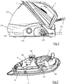
- the figure 1 shows an ironing appliance comprising a steam generator base 100 and an iron 1 connected to each other by a duct 101, the iron 1 comprising a plastic housing incorporating a handle.
- the base 100 comprises an inclined plane on which the iron 1 can come to rest during inactive ironing phases and contains, in a manner known per se, a tank 102 for the production of steam under a pressure of the order of 4 to 6 bars, the tank 102 being supplied with water from a reservoir 103 by means of a pump 104.
- the base 100 is connected to the domestic electrical network by an electrical wire 105 which allows both the electrical supply of the heating means of the tank 102 and the electrical supply of the iron 1 through the conduit 101.
- the iron 1 comprises a cap 2 which comprises a flat lower surface defining an ironing surface intended to come into contact with the laundry, the cap 2 being contiguous to a heating sole 3 comprising a substantially flat lower wall coming directly into contact with the cover 2, the latter being bonded to the heating sole 3 by a silicone adhesive.
- the cover 2 is advantageously constituted by an aluminum sheet, with a thickness of the order of 1.4 mm, covered with enamel on its underside, and comprises a front part, disposed in front of the transverse axis Y passing through the middle of the cover 2, generally having a triangular shape with a point at its front end and a rear part, arranged behind the transverse axis Y, of greater width ending in a rounded rear edge.
- the heating sole 3 consists of an aluminum foundry in which is embedded a heating element consisting of a first U-shaped shielded electrical resistance 31, the latter extending only in a rear part of the heating sole. 3 surmounting the rear part of the cap 2 so as to generate at the rear part of the cap 2 a so-called hot zone where the temperature of the ironing surface is the highest.
- the power supply to the first electrical resistance 31 is regulated by means of a first thermostat, advantageously constituted by a relay controlled by an electronic card connected to a CTN probe (not shown in the figures) placed on a boss 32 provided on the rear part of the heated sole 3.
- the first electrical resistance 31 advantageously has a power of between 300 W and 600 W and the first thermostat comprises a setpoint temperature which is adjustable by the user over a range advantageously between 90 ° C and 240 ° C, and preferably between 110 ° C and 200 ° C, this setpoint temperature of the first thermostat corresponding to the temperature at a point A located in the hot zone of the ironing surface, near the center of the hood 2.
- the heating soleplate 3 may be produced by molding in an aluminum alloy foundry having a mass of the order of 175 g which is molded onto a shielded electrical resistance with a power of the order of 450 W.
- the heating sole 3 comprises, facing the front part of the cover 2, a front part devoid of a heating element, this front part comprising a through opening 30 limiting the heat exchange taking place by conduction between the heating sole 3 and the cap 2 and thus generating, in the front part of the cap 2, a so-called cold zone where the temperature of the ironing surface is lower than in the hot zone located in the rear part of the cap.
- the opening 30 has a generally triangular shape, matching the shape of the front part of the cover 2, the width of which represents at least 65% of the width of the cover 2.
- the opening 30 furthermore comprises, at its rear end, two protuberances extending on either side of the rounded front end of the first electrical resistance 31.
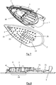
- the iron 1 also comprises a heating body 4 which is attached to the heating sole 3, this heating body 4 preferably being constituted by an aluminum foundry in which is embedded a heating element constituted by a second electrical resistance 41 shielded in the form of U, also having a power advantageously between 300 W and 600 W.
- the heating body 4 is disposed above the opening 30 and has a generally triangular outline matching the general shape of the opening 30, the heating body 4 comprising a peripheral edge comprising six fixing holes 40 intended to receive stainless steel screws which are fixed on six fixing studs 33 provided on the heating soleplate 3, at the edge of the opening 30, a silicone seal 5 being advantageously arranged between the heating body 4 and the heating sole 3.
- the heating body 4 comprises an upper face on which protrudes a peripheral wall 42 which laterally delimits a space comprising a vaporization chamber 43, of the instantaneous vaporization type, the vaporization chamber 43 being arranged directly above the cold zone of the ironing surface and being closed at its upper end by a cover 6 which comes to rest on the upper edge of the peripheral wall 42.
- the heating body 4 may be produced by molding in an aluminum alloy foundry having a mass of the order of 175 g which is overmolded on a shielded electrical resistance with a power of the order of 450 W, the cover 6 being produced in an aluminum alloy foundry having a mass of the order of 80 g.
- the cover 6 supports a second thermostat 60 fixed on a stud 44 projecting into the vaporization chamber 43 and passing through the cover 6, the second thermostat 60 being connected to the second electrical resistance 41 to regulate the temperature of the vaporization chamber 43 around a fixed setpoint temperature, not adjustable by the user, slightly greater than 100 ° C and preferably of the order of 105 ° C.
- the second thermostat 60 is advantageously produced by means of a mechanical thermostat of the bimetal type, the precision required for the temperature regulation of the heating body 4 being less important than that required for the temperature regulation of the heating sole 3.
- the cover 6 comprises a connector 61, which is connected to a steam pipe, not shown in the figures, which is integrated in the duct 101 connecting the steam generator base 100 to the iron 1, this connector 61 making it possible to supply the vaporization chamber 43 with the vapor produced by the tank 102.
- the connector 61 opens into the vaporization chamber 43 at an injection point 45 from which the vapor escapes through a condensate separation device, the latter comprising a first pipe 43A extending in the form of a spiral around a circular central volume where the stud 44 and a second pipe 43B protrude, communicating with this central volume via a lateral opening 43C.
- the second pipe 43B extends outside the first pipe 43A and has a shape such that the flow of steam makes a 180 ° turn passing from the first pipe 43A to the second pipe 43B through the side opening 43C .
- the second pipe 43B then extends in the direction of the front end of the heating body 4 where it communicates with two passages 46 passing through the heating body 4 to open out on the underside of the heating body 4, in a vapor diffusion chamber 7. formed in the opening 30 of the heating sole 3, between the vaporization chamber 43 and the cap 2.
- the diffusion chamber 7 makes it possible to supply steam to a first group 21 of steam outlet holes 20 located mainly in the front part of the cap 2, in the cold zone of the ironing surface, and a second group 22 of steam outlet holes 20 arranged in the rear part of the cap 2, in the hot zone of the ironing surface.
- the vapor outlet holes 20 of the first group 21 are mainly arranged directly opposite the diffusion chamber 7 so that the vapor diffused by these holes does not come into contact with the heating sole 3 and is not heated by this last before to be diffused outside the cover 2.
- the steam outlet holes 20 of the first group 21 are distributed over the entire surface of the cap 2 surmounted by the opening 30 so as to diffuse steam over a width corresponding to at least 65% of the width. of the cover 2.
- the steam outlet holes 20 of the second group 22 are for their part supplied indirectly, by means of distribution channels 47 formed on the rear part of the cover 2 at which the steam is heated before being diffused through the outside of the fairing 2.
- the tank 102 When the appliance is started up, the tank 102 is heated and the water it contains is brought to a boil, the pressurized steam produced by the tank 102 being transmitted through the pipe 101 to the iron 1. When This transmission of the steam through the duct 101, the temperature of the steam is lowered so that condensates form in the flow of steam arriving in the iron 1.
- the largest condensates are eliminated during the passage of the vapor flow in the vaporization chamber 43.
- the flow of the vapor through the first and second pipes 43A, 43B makes it possible to separate the condensates from the vapor of water, the sudden change in direction of the steam flow being established at the inlet of the second pipe 43B making it possible to separate the condensates from the steam flow and to retain them in the central volume.
- the sudden increase in the passage section being established at the level of the central volume of the vaporization chamber 43 makes it possible to lower the speed of the vapor flow and to collect by gravity, in the bottom of the central volume, the vapor. condensates transported in the form of large drops or in the form of a liquid film entrained on the walls of the vaporization chamber 43 by the flow of steam.
- Such a construction of the vaporization chamber 43 makes it possible to obtain a vapor at the outlet of the vaporization chamber 43 loaded only with micro-droplets of water, this vapor passing through the passages 46 to be delivered into the diffusion chamber 7. cut above the front part of the fairing 2.
- the diffusion chamber 7 being remote from the hot zone of the cap 2, the vapor therein is diffused through the vapor outlet holes 20 of the first group 21 with a high moisture content, that is to say - say by being loaded with micro-droplets of liquid water which are deposited on the fabric being ironed.
- such a construction makes it possible to establish a strong thermal gradient between a point B located in the cold zone of the ironing surface and point A located in the hot zone of the ironing surface, thanks to a geometry which makes it possible to limit the heat flow between the center of the cover 2, subjected directly to the heating of the heating sole 3, and the front part of the cover 2.
- the opening 30 made in the heating sole 3 makes it possible to limit approximately 18 W the maximum heat flux being able to pass by conduction through the peripheral edges of the heating soleplate 3 which laterally border the opening 30, when the point A of the cap 2 is at a temperature of 180 ° C.
- the temperature of the heating sole 3, and therefore of the rear part of the ironing surface can be regulated around a set temperature which can reach more than 240 ° C, while maintaining a temperature in the front part of the ironing surface, and in particular in the vicinity of point B, of the of the order of 100 ° C, the temperature of the ironing surface possibly reaching a maximum temperature of around 130 ° C on the peripheral zone where the cap 2 is in contact with the peripheral edges of the heating sole 3 which border the opening 30.
- the steam, at high humidity, emitted by the steam outlet holes 20 of the first group 21 can therefore condense quickly in the thickness of the laundry, allowing better ironing performance to be obtained, this condensation in the laundry. being favored by the low temperature of the ironing surface, close to 100 ° C., in the vicinity of the steam outlet holes 20 of the first group 21 which avoids overheating the laundry.
- the temperature of the front part of the cap 2 remains above 90 ° C thanks to the heat exchange being established by radiation with the body heating 4, by convection through the steam, or by conduction with the part of the heating sole 3 bordering the opening 30, which is sufficient to prevent the steam from condensing directly on the cap 2, creating a wetting of the laundry by capillary action which would generate too long a drying time.
- the steam emitted by the second group 22 of steam outlet holes 20 has the advantage of having a lower humidity level than that of the steam emitted by the first group 21, due to the heating of the steam taking place during its diffusion through the distribution channels of the heating soleplate 3, so that the emission of steam through these holes does not interfere with the drying of the laundry by the rear part of the cap 2.
- the presence of the steam outlet holes 20 of the second group 22 improves the efficiency of the iron when only the rear part of the cap 2 is used to iron a particular area of the laundry on which the iron 1 is moved only rearward.
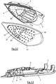
- the figure 8 illustrates a sub-assembly of an iron according to a second embodiment of the invention.
- This sub-assembly differs from the iron previously described for the first embodiment in that the ironing surface is constituted directly by a flat lower face of the heating sole 3, the iron not having a cap attached under the heated sole 3.
- the heating soleplate 3 comprises, in the front part of the ironing surface, a zone 34 where the thickness of the heating soleplate 3 is reduced, this zone 34 being located in place of the through opening. provided in the first embodiment and advantageously representing at least 65% of the surface of the front part of the ironing surface.
- the zone 34 where the thickness of the heating sole 3 is reduced forms a cavity in the upper part of the heating sole 3 which is closed in its upper part by the heating body 4 and together with the latter constitutes the vapor diffusion chamber 7 , the zone 34 of the heating sole being provided with vapor outlet holes 20.
- the operation of the iron according to this second embodiment is similar to that described for the first embodiment, the reduced thickness of the heating sole 3 at the level of the zone 34 making it possible to limit the heat transfer by conduction through the heating sole 3 between the hot zone, located in the rear part of the ironing surface, and the cold zone, located in the front part of the ironing surface.
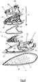
- the figures 9 to 11 illustrate a sub-assembly of an iron according to a third embodiment of the invention.
- This iron differs from the iron described in the first embodiment only in that it comprises, in addition to all the elements described for the first embodiment, a collector 8 arranged across the opening 30. the heated soleplate 3.
- This collector 8 is mechanically integral with the heating body 4 and has dimensions slightly smaller than those of the opening 30 so as to take place in the opening 30 without being in contact with the heating sole 3.
- the manifold 8 is advantageously produced by stamping a sheet of stainless steel or aluminum alloy crimped on pins projecting on the underside of the heating body 4, the manifold 8 preferably comprising an exhaust port 80 in sight of each hole 20 of the vapor outlet of the first group 21 in order to pre-orient the flow of vapor in the direction of the latter.
- Such a manifold 8 makes it possible to further limit the heat exchanges established between the flow of steam and the heating soleplate 3, which makes it possible to further lower the temperature of the steam at the outlet of the steam outlet holes 20 of the first group. 21, for greater humidity of the laundry and better ironing performance.
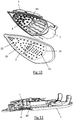
- the figures 12 and 13 illustrate a cap / heating sole / heating body sub-assembly of an iron according to a fourth embodiment of the invention.
- the iron according to this embodiment differs from the iron according to the first embodiment both by the presence of a collector 8 across the opening 30 of the heating sole 3 and by the shape of the cap 2.
- the manifold 8 is provided with exhaust orifices 80 which make it possible, just as for the third embodiment described above, to pre-orient the flow of steam in the direction of steam outlet holes 20 of the first group 21 to limit the heat exchanges being established between the steam flow and the heating soleplate.
- the iron also comprises a cap 2 which has the particularity of having a recessed area 23 in its front part at which the cap 2 comprises a plane which is set back by the order of 2 to 5 mm. relative to the ironing plane of the cover 2 coming into contact with the laundry.
- the hollow zone receives part of the steam outlet holes 20 of the first group 21 thus forming a cavity located between the cap 2 and the clothes to be ironed in which the steam coming from the vaporization chamber 43 is diffused.
- Such a hollow zone 23 makes it possible, by limiting the heat exchange taking place between the cover 2 and the linen, to further improve the humidification of the linen, the vapor diffused in the cavity coming to condense more significantly in the laundry due to its lower temperature.
- the cap could include only the first group of steam outlet holes and be devoid of the second group of steam outlet holes.
- the vessel for the production of steam can be installed directly in the iron and / or be constituted by an instantaneous vaporization chamber.
- the heating element could be produced by a screen printed flat heating element.
- the setpoint temperature of the second thermostat can be adjusted automatically by a control unit as a function of the setpoint temperature of the first. thermostat or according to the temperature measurement of the heating soleplate.
Landscapes
- Engineering & Computer Science (AREA)
- Textile Engineering (AREA)
- Irons (AREA)
Claims (13)
- Bügeleisen (1) mit einer Bügelfläche, einer Heizsohle (3), die zum Beheizen der Bügelfläche vorgesehen ist, und einer Dampfkammer (43), wobei die Heizsohle (3) einen ersten elektrischen Widerstand (31) umfasst, der senkrecht zu einer sogenannten heißen Zone der Bügelfläche angeordnet ist, wobei die Dampfkammer (43) in einem Heizkörper (4) mit einem zweiten elektrischen Widerstand (41) ausgebildet ist, wobei die Dampfkammer (43) senkrecht zu einer sogenannten kalten Zone der Bügelfläche mit Dampfaustrittslöchern (20) angeordnet ist, wobei die Dampfaustrittslöcher (20) von einer außerhalb der Dampfkammer (43) angeordneten Dampfdiffusionskammer (7) in einen zwischen der Dampfkammer (43) und der kalten Zone der Bügelfläche gebildeten Hohlraum gespeist werden, wobei der Heizkörper (4) und die Heizsohle (3) in zwei getrennten Teilen ausgeführt sind, dadurch gekennzeichnet, dass der Heizkörper (4) auf der Heizsohle (3) angebracht ist.
- Bügeleisen (1) nach Anspruch 1, dadurch gekennzeichnet, dass die Bügelfläche von einer Kappe (2) getragen wird, die unter der Stirnseite der Heizsohle (3) angebracht ist, und dass die Heizsohle (3) gegenüber der kalten Zone eine Öffnung (30) aufweist, die zumindest teilweise von der Kappe (2) verdeckt ist, wobei sich der Heizkörper oberhalb dieser Öffnung (30) erstreckt.
- Bügeleisen (1) nach Anspruch 1, dadurch gekennzeichnet, dass die Bügelfläche durch eine Unterseite der Heizsohle (3) gebildet wird und dass die Heizsohle (3) im Bereich der kalten Zone einen Teil (34) aufweist, in dem ihre Dicke im Verhältnis zu ihrer Dicke gegenüber der heißen Zone reduziert ist.
- Bügeleisen (1) nach einem der Ansprüche 1 bis 3, dadurch gekennzeichnet, dass die heiße Zone der Bügelfläche als die kleinste geschlossene konvexe Fläche definiert ist, in der die Orthogonalprojektion des ersten elektrischen Widerstands (31) liegt.
- Bügeleisen (1) nach einem der Ansprüche 1 bis 4, dadurch gekennzeichnet, dass die Speisung des ersten elektrischen Widerstands (31) mittels eines ersten Thermostats geregelt wird, um die heiße Zone um eine Solltemperatur zwischen 90° und 240°C zu halten.
- Bügeleisen (1) nach Anspruch 5, dadurch gekennzeichnet, dass die Solltemperatur des ersten Thermostats durch den Benutzer einstellbar ist.
- Bügeleisen (1) nach einem der Ansprüche 1 bis 6, dadurch gekennzeichnet, dass die Stromversorgung des zweiten elektrischen Widerstands (41) mittels eines zweiten Thermostats (60) geregelt wird, um die Temperatur der Dampfkammer (43) um eine Solltemperatur zwischen 100°C und 135°C zu halten.
- Bügeleisen (1) nach Anspruch 7, dadurch gekennzeichnet, dass die Solltemperatur des zweiten Thermostats (60) nicht vom Benutzer einstellbar ist.
- Bügeleisen (1) nach einem der Ansprüche 1 bis 8, dadurch gekennzeichnet, dass die kalte Zone auf der vorderen Hälfte der Bügelfläche und die heiße Zone auf der hinteren Hälfte der Bügelfläche angeordnet ist.
- Bügeleisen (1) nach einem der Ansprüche 1 bis 9, dadurch gekennzeichnet, dass die heiße Zone der Bügelfläche Dampfaustrittslöcher (20) aufweist.
- Bügeleisen (1) nach einem der Ansprüche 1 bis 10, dadurch gekennzeichnet, dass der Heizkörper (4) mit der Heizsohle (3) durch am Rand des die Diffusionskammer (7) bildenden Hohlraums angeordnete Befestigungspunkte mechanisch gekoppelt ist.
- Bügeleisen (1) nach Anspruch 11, dadurch gekennzeichnet, dass zwischen dem Heizkörper (4) und der Heizsohle (3) eine Dichtung (5) angeordnet ist.
- Bügeleisen (1) nach einem der Ansprüche 1 bis 12, dadurch gekennzeichnet, dass es einen Verteiler (8) aufweist, der sich in der Diffusionskammer (7) befindet, wobei der Verteiler (8) eine Öffnung (80) gegenüber jedem der Dampfaustrittslöcher (20) der kalten Zone der Bügelfläche aufweist.
Applications Claiming Priority (1)
| Application Number | Priority Date | Filing Date | Title |
|---|---|---|---|
| FR1662364A FR3060033B1 (fr) | 2016-12-13 | 2016-12-13 | Fer a repasser comportant une surface de repassage, une semelle chauffante et une chambre de vaporisation |
Publications (2)
| Publication Number | Publication Date |
|---|---|
| EP3336244A1 EP3336244A1 (de) | 2018-06-20 |
| EP3336244B1 true EP3336244B1 (de) | 2021-03-17 |
Family
ID=58054307
Family Applications (1)
| Application Number | Title | Priority Date | Filing Date |
|---|---|---|---|
| EP17206032.9A Active EP3336244B1 (de) | 2016-12-13 | 2017-12-07 | Bügeleisen, das eine bügelfläche, eine heizsohle und eine dampfkammer besitzt |
Country Status (3)
| Country | Link |
|---|---|
| EP (1) | EP3336244B1 (de) |
| CN (2) | CN208167372U (de) |
| FR (1) | FR3060033B1 (de) |
Families Citing this family (1)
| Publication number | Priority date | Publication date | Assignee | Title |
|---|---|---|---|---|
| FR3060033B1 (fr) * | 2016-12-13 | 2018-11-23 | Seb S.A. | Fer a repasser comportant une surface de repassage, une semelle chauffante et une chambre de vaporisation |
Family Cites Families (18)
| Publication number | Priority date | Publication date | Assignee | Title |
|---|---|---|---|---|
| FR2654122B1 (fr) * | 1989-11-07 | 1993-07-30 | Moulinex Sa | Fer a repasser electrique. |
| DE4107236A1 (de) * | 1991-03-07 | 1992-09-10 | Braun Ag | Dampfbuegeleisen |
| FR2700560B1 (fr) * | 1993-01-20 | 1995-09-08 | Moulinex Sa | Dispositif de repassage a vapeur. |
| FR2704248B1 (fr) * | 1993-04-23 | 1995-11-10 | Moulinex Sa | Fer a repasser et procede de fabrication d'un tel fer. |
| FR2740787B1 (fr) * | 1995-11-03 | 1999-06-11 | Moulinex Sa | Fer a repasser a vapeur |
| JP3288013B2 (ja) * | 1998-07-17 | 2002-06-04 | 直本工業株式会社 | 業務用アイロン及びスチームブラシ |
| US6953912B2 (en) * | 2001-11-21 | 2005-10-11 | Celaya Emparanza Y Galdos, Internacional, S.A. | Domestic steam iron with autonomous steam assembly heated by separate heating element |
| FR2899907B1 (fr) * | 2006-04-18 | 2008-10-17 | Domena Soc Par Actions Simplif | Fer a repasser a double chambre de vaporisation |
| GB2437283A (en) * | 2006-04-22 | 2007-10-24 | Richards Morphy N I Ltd | Steam iron |
| CN201183911Y (zh) * | 2008-04-16 | 2009-01-21 | 李文庆 | 蒸气熨斗的底座 |
| JP2010240150A (ja) * | 2009-04-06 | 2010-10-28 | Toyonaka Hot Kenkyusho:Kk | スチーム機器用加熱装置 |
| FR2971796B1 (fr) * | 2011-02-18 | 2014-05-09 | Seb Sa | Fer a repasser a vapeur comportant une plaque de repassage comprenant au moins un premier groupe et un deuxieme groupe de trous de sortie de vapeur |
| FR3000111B1 (fr) * | 2012-12-21 | 2015-01-02 | Seb Sa | Appareil de repassage a la vapeur comportant un generateur de vapeur sous pression et un fer a repasser |
| FR3001234B1 (fr) * | 2013-01-22 | 2015-12-25 | Seb Sa | Appareil de repassage a la vapeur comportant un generateur de vapeur et un fer a repasser |
| FR3006337B1 (fr) * | 2013-05-30 | 2015-05-22 | Seb Sa | Appareil de repassage a la vapeur comprenant un fer a repasser |
| FR3011559B1 (fr) * | 2013-10-04 | 2015-11-06 | Seb Sa | Appareil de repassage comportant une base generatrice de vapeur et un fer a repasser relies entre eux par un conduit de vapeur |
| EP3098345B1 (de) * | 2015-05-29 | 2019-07-03 | Sda Factory Victoria Slu | Dampfbügeleisen und verfahren zum betrieb eines dampfbügeleisens |
| FR3060033B1 (fr) * | 2016-12-13 | 2018-11-23 | Seb S.A. | Fer a repasser comportant une surface de repassage, une semelle chauffante et une chambre de vaporisation |
-
2016
- 2016-12-13 FR FR1662364A patent/FR3060033B1/fr not_active Expired - Fee Related
-
2017
- 2017-12-07 EP EP17206032.9A patent/EP3336244B1/de active Active
- 2017-12-12 CN CN201721722958.7U patent/CN208167372U/zh not_active Withdrawn - After Issue
- 2017-12-12 CN CN201711321421.4A patent/CN108611833B/zh active Active
Non-Patent Citations (1)
| Title |
|---|
| None * |
Also Published As
| Publication number | Publication date |
|---|---|
| CN108611833A (zh) | 2018-10-02 |
| CN208167372U (zh) | 2018-11-30 |
| FR3060033B1 (fr) | 2018-11-23 |
| EP3336244A1 (de) | 2018-06-20 |
| CN108611833B (zh) | 2021-06-25 |
| FR3060033A1 (fr) | 2018-06-15 |
Similar Documents
| Publication | Publication Date | Title |
|---|---|---|
| EP3336242A1 (de) | Dampfbügelgerät, das eine dampferzeugende basis und ein bügeleisen umfasst, die über eine leitung miteinander verbunden sind | |
| EP2757190B1 (de) | Dampfbügelgerät, das einen dampfdruckerzeuger und ein bügeleisen umfasst | |
| EP2808438B1 (de) | Dampfbügelgerät, das ein Bügeleisen umfasst | |
| FR3060027A1 (fr) | Appareil de defroissage a la vapeur | |
| EP3246459B1 (de) | Dampfbügeleisen mit heizkörper, der eine dampfkammer und eine bügelfläche umfasst, die in wärmeverbindung mit dem heizkörper steht | |
| EP2578743B1 (de) | Elektrohaushaltsgerät, das einen Dampfverteilungskreis umfasst | |
| EP4551749A1 (de) | Knitterglättungsvorrichtung | |
| EP3336243B1 (de) | Bügeleisen, das eine bügelfläche, eine heizsohle und eine dampfkammer besitzt | |
| EP3266927B1 (de) | Bügeleisen, das einen heizkörper in thermischem kontakt mit einer bügelplatte umfasst | |
| EP3336240B1 (de) | Bügeleisen, das eine rückhalte- und verdampfungsvorrichtung von kondensaten umfasst | |
| EP3868951B1 (de) | Tragbares dampfentknitterungsgerät | |
| EP2808439B1 (de) | Dampfbügelgerät | |
| EP3336245B1 (de) | Dampfbügelgerät, das eine dampferzeugende basis und ein bügeleisen umfasst, die über eine leitung miteinander verbunden sind | |
| EP3336244B1 (de) | Bügeleisen, das eine bügelfläche, eine heizsohle und eine dampfkammer besitzt | |
| FR3129410A1 (fr) | Appareil de Traitement du linge à vapeur | |
| EP3002364B1 (de) | Dampfbügelgerät, das ein bügeleisen mit einer grundplatte umfasst, auf die ein mit einem heizelement ausgestatteter körper montiert ist | |
| FR3124200A1 (fr) | appareil de défroissage portatif comprenant une poignée renfermant un conduit de vapeur | |
| WO2026012724A1 (fr) | Appareil de défroissage | |
| WO2024223129A1 (fr) | Fer à repasser comprenant un générateur de vapeur | |
| WO2023280724A1 (fr) | Appareil pour le traitement du linge à la vapeur comportant une base destinée à reposer sur un support | |
| WO2026012720A1 (fr) | Appareil de défroissage | |
| EP4299825A1 (de) | Elektrisches haushaltsgerät zum bügeln und/oder glätten mit einer vorrichtung zum zurückhalten von dampfgetragenen kalkpartikeln | |
| FR3164486A1 (fr) | Appareil de défroissage | |
| FR3137111A1 (fr) | Appareil électroménager de repassage et/ou défroissage comportant au moins deux chambres de vaporisation reliées entre elles par un conduit de liaison. |
Legal Events
| Date | Code | Title | Description |
|---|---|---|---|
| PUAI | Public reference made under article 153(3) epc to a published international application that has entered the european phase |
Free format text: ORIGINAL CODE: 0009012 |
|
| STAA | Information on the status of an ep patent application or granted ep patent |
Free format text: STATUS: THE APPLICATION HAS BEEN PUBLISHED |
|
| AK | Designated contracting states |
Kind code of ref document: A1 Designated state(s): AL AT BE BG CH CY CZ DE DK EE ES FI FR GB GR HR HU IE IS IT LI LT LU LV MC MK MT NL NO PL PT RO RS SE SI SK SM TR |
|
| AX | Request for extension of the european patent |
Extension state: BA ME |
|
| STAA | Information on the status of an ep patent application or granted ep patent |
Free format text: STATUS: REQUEST FOR EXAMINATION WAS MADE |
|
| 17P | Request for examination filed |
Effective date: 20181205 |
|
| RBV | Designated contracting states (corrected) |
Designated state(s): AL AT BE BG CH CY CZ DE DK EE ES FI FR GB GR HR HU IE IS IT LI LT LU LV MC MK MT NL NO PL PT RO RS SE SI SK SM TR |
|
| STAA | Information on the status of an ep patent application or granted ep patent |
Free format text: STATUS: EXAMINATION IS IN PROGRESS |
|
| 17Q | First examination report despatched |
Effective date: 20200416 |
|
| REG | Reference to a national code |
Ref country code: DE Ref legal event code: R079 Ref document number: 602017034677 Country of ref document: DE Free format text: PREVIOUS MAIN CLASS: D06F0075100000 Ipc: D06F0075240000 |
|
| GRAP | Despatch of communication of intention to grant a patent |
Free format text: ORIGINAL CODE: EPIDOSNIGR1 |
|
| STAA | Information on the status of an ep patent application or granted ep patent |
Free format text: STATUS: GRANT OF PATENT IS INTENDED |
|
| RIC1 | Information provided on ipc code assigned before grant |
Ipc: D06F 75/24 20060101AFI20201001BHEP Ipc: D06F 75/38 20060101ALN20201001BHEP |
|
| INTG | Intention to grant announced |
Effective date: 20201103 |
|
| GRAS | Grant fee paid |
Free format text: ORIGINAL CODE: EPIDOSNIGR3 |
|
| GRAA | (expected) grant |
Free format text: ORIGINAL CODE: 0009210 |
|
| STAA | Information on the status of an ep patent application or granted ep patent |
Free format text: STATUS: THE PATENT HAS BEEN GRANTED |
|
| AK | Designated contracting states |
Kind code of ref document: B1 Designated state(s): AL AT BE BG CH CY CZ DE DK EE ES FI FR GB GR HR HU IE IS IT LI LT LU LV MC MK MT NL NO PL PT RO RS SE SI SK SM TR |
|
| REG | Reference to a national code |
Ref country code: GB Ref legal event code: FG4D Free format text: NOT ENGLISH |
|
| REG | Reference to a national code |
Ref country code: CH Ref legal event code: EP |
|
| REG | Reference to a national code |
Ref country code: DE Ref legal event code: R096 Ref document number: 602017034677 Country of ref document: DE |
|
| REG | Reference to a national code |
Ref country code: IE Ref legal event code: FG4D Free format text: LANGUAGE OF EP DOCUMENT: FRENCH |
|
| REG | Reference to a national code |
Ref country code: AT Ref legal event code: REF Ref document number: 1372344 Country of ref document: AT Kind code of ref document: T Effective date: 20210415 |
|
| REG | Reference to a national code |
Ref country code: LT Ref legal event code: MG9D |
|
| PG25 | Lapsed in a contracting state [announced via postgrant information from national office to epo] |
Ref country code: BG Free format text: LAPSE BECAUSE OF FAILURE TO SUBMIT A TRANSLATION OF THE DESCRIPTION OR TO PAY THE FEE WITHIN THE PRESCRIBED TIME-LIMIT Effective date: 20210617 Ref country code: NO Free format text: LAPSE BECAUSE OF FAILURE TO SUBMIT A TRANSLATION OF THE DESCRIPTION OR TO PAY THE FEE WITHIN THE PRESCRIBED TIME-LIMIT Effective date: 20210617 Ref country code: HR Free format text: LAPSE BECAUSE OF FAILURE TO SUBMIT A TRANSLATION OF THE DESCRIPTION OR TO PAY THE FEE WITHIN THE PRESCRIBED TIME-LIMIT Effective date: 20210317 Ref country code: GR Free format text: LAPSE BECAUSE OF FAILURE TO SUBMIT A TRANSLATION OF THE DESCRIPTION OR TO PAY THE FEE WITHIN THE PRESCRIBED TIME-LIMIT Effective date: 20210618 Ref country code: FI Free format text: LAPSE BECAUSE OF FAILURE TO SUBMIT A TRANSLATION OF THE DESCRIPTION OR TO PAY THE FEE WITHIN THE PRESCRIBED TIME-LIMIT Effective date: 20210317 |
|
| REG | Reference to a national code |
Ref country code: AT Ref legal event code: MK05 Ref document number: 1372344 Country of ref document: AT Kind code of ref document: T Effective date: 20210317 |
|
| REG | Reference to a national code |
Ref country code: NL Ref legal event code: MP Effective date: 20210317 |
|
| PG25 | Lapsed in a contracting state [announced via postgrant information from national office to epo] |
Ref country code: LV Free format text: LAPSE BECAUSE OF FAILURE TO SUBMIT A TRANSLATION OF THE DESCRIPTION OR TO PAY THE FEE WITHIN THE PRESCRIBED TIME-LIMIT Effective date: 20210317 Ref country code: RS Free format text: LAPSE BECAUSE OF FAILURE TO SUBMIT A TRANSLATION OF THE DESCRIPTION OR TO PAY THE FEE WITHIN THE PRESCRIBED TIME-LIMIT Effective date: 20210317 Ref country code: SE Free format text: LAPSE BECAUSE OF FAILURE TO SUBMIT A TRANSLATION OF THE DESCRIPTION OR TO PAY THE FEE WITHIN THE PRESCRIBED TIME-LIMIT Effective date: 20210317 |
|
| PG25 | Lapsed in a contracting state [announced via postgrant information from national office to epo] |
Ref country code: NL Free format text: LAPSE BECAUSE OF FAILURE TO SUBMIT A TRANSLATION OF THE DESCRIPTION OR TO PAY THE FEE WITHIN THE PRESCRIBED TIME-LIMIT Effective date: 20210317 |
|
| PG25 | Lapsed in a contracting state [announced via postgrant information from national office to epo] |
Ref country code: LT Free format text: LAPSE BECAUSE OF FAILURE TO SUBMIT A TRANSLATION OF THE DESCRIPTION OR TO PAY THE FEE WITHIN THE PRESCRIBED TIME-LIMIT Effective date: 20210317 Ref country code: CZ Free format text: LAPSE BECAUSE OF FAILURE TO SUBMIT A TRANSLATION OF THE DESCRIPTION OR TO PAY THE FEE WITHIN THE PRESCRIBED TIME-LIMIT Effective date: 20210317 Ref country code: EE Free format text: LAPSE BECAUSE OF FAILURE TO SUBMIT A TRANSLATION OF THE DESCRIPTION OR TO PAY THE FEE WITHIN THE PRESCRIBED TIME-LIMIT Effective date: 20210317 Ref country code: AT Free format text: LAPSE BECAUSE OF FAILURE TO SUBMIT A TRANSLATION OF THE DESCRIPTION OR TO PAY THE FEE WITHIN THE PRESCRIBED TIME-LIMIT Effective date: 20210317 Ref country code: SM Free format text: LAPSE BECAUSE OF FAILURE TO SUBMIT A TRANSLATION OF THE DESCRIPTION OR TO PAY THE FEE WITHIN THE PRESCRIBED TIME-LIMIT Effective date: 20210317 |
|
| PG25 | Lapsed in a contracting state [announced via postgrant information from national office to epo] |
Ref country code: IS Free format text: LAPSE BECAUSE OF FAILURE TO SUBMIT A TRANSLATION OF THE DESCRIPTION OR TO PAY THE FEE WITHIN THE PRESCRIBED TIME-LIMIT Effective date: 20210717 Ref country code: RO Free format text: LAPSE BECAUSE OF FAILURE TO SUBMIT A TRANSLATION OF THE DESCRIPTION OR TO PAY THE FEE WITHIN THE PRESCRIBED TIME-LIMIT Effective date: 20210317 Ref country code: SK Free format text: LAPSE BECAUSE OF FAILURE TO SUBMIT A TRANSLATION OF THE DESCRIPTION OR TO PAY THE FEE WITHIN THE PRESCRIBED TIME-LIMIT Effective date: 20210317 Ref country code: PT Free format text: LAPSE BECAUSE OF FAILURE TO SUBMIT A TRANSLATION OF THE DESCRIPTION OR TO PAY THE FEE WITHIN THE PRESCRIBED TIME-LIMIT Effective date: 20210719 Ref country code: PL Free format text: LAPSE BECAUSE OF FAILURE TO SUBMIT A TRANSLATION OF THE DESCRIPTION OR TO PAY THE FEE WITHIN THE PRESCRIBED TIME-LIMIT Effective date: 20210317 |
|
| REG | Reference to a national code |
Ref country code: DE Ref legal event code: R097 Ref document number: 602017034677 Country of ref document: DE |
|
| PLBE | No opposition filed within time limit |
Free format text: ORIGINAL CODE: 0009261 |
|
| STAA | Information on the status of an ep patent application or granted ep patent |
Free format text: STATUS: NO OPPOSITION FILED WITHIN TIME LIMIT |
|
| PG25 | Lapsed in a contracting state [announced via postgrant information from national office to epo] |
Ref country code: ES Free format text: LAPSE BECAUSE OF FAILURE TO SUBMIT A TRANSLATION OF THE DESCRIPTION OR TO PAY THE FEE WITHIN THE PRESCRIBED TIME-LIMIT Effective date: 20210317 Ref country code: DK Free format text: LAPSE BECAUSE OF FAILURE TO SUBMIT A TRANSLATION OF THE DESCRIPTION OR TO PAY THE FEE WITHIN THE PRESCRIBED TIME-LIMIT Effective date: 20210317 Ref country code: AL Free format text: LAPSE BECAUSE OF FAILURE TO SUBMIT A TRANSLATION OF THE DESCRIPTION OR TO PAY THE FEE WITHIN THE PRESCRIBED TIME-LIMIT Effective date: 20210317 |
|
| 26N | No opposition filed |
Effective date: 20211220 |
|
| PG25 | Lapsed in a contracting state [announced via postgrant information from national office to epo] |
Ref country code: SI Free format text: LAPSE BECAUSE OF FAILURE TO SUBMIT A TRANSLATION OF THE DESCRIPTION OR TO PAY THE FEE WITHIN THE PRESCRIBED TIME-LIMIT Effective date: 20210317 |
|
| PG25 | Lapsed in a contracting state [announced via postgrant information from national office to epo] |
Ref country code: IS Free format text: LAPSE BECAUSE OF FAILURE TO SUBMIT A TRANSLATION OF THE DESCRIPTION OR TO PAY THE FEE WITHIN THE PRESCRIBED TIME-LIMIT Effective date: 20210717 |
|
| PG25 | Lapsed in a contracting state [announced via postgrant information from national office to epo] |
Ref country code: MC Free format text: LAPSE BECAUSE OF FAILURE TO SUBMIT A TRANSLATION OF THE DESCRIPTION OR TO PAY THE FEE WITHIN THE PRESCRIBED TIME-LIMIT Effective date: 20210317 |
|
| REG | Reference to a national code |
Ref country code: CH Ref legal event code: PL |
|
| GBPC | Gb: european patent ceased through non-payment of renewal fee |
Effective date: 20211207 |
|
| REG | Reference to a national code |
Ref country code: BE Ref legal event code: MM Effective date: 20211231 |
|
| PG25 | Lapsed in a contracting state [announced via postgrant information from national office to epo] |
Ref country code: LU Free format text: LAPSE BECAUSE OF NON-PAYMENT OF DUE FEES Effective date: 20211207 Ref country code: IE Free format text: LAPSE BECAUSE OF NON-PAYMENT OF DUE FEES Effective date: 20211207 Ref country code: GB Free format text: LAPSE BECAUSE OF NON-PAYMENT OF DUE FEES Effective date: 20211207 |
|
| PG25 | Lapsed in a contracting state [announced via postgrant information from national office to epo] |
Ref country code: BE Free format text: LAPSE BECAUSE OF NON-PAYMENT OF DUE FEES Effective date: 20211231 |
|
| PG25 | Lapsed in a contracting state [announced via postgrant information from national office to epo] |
Ref country code: LI Free format text: LAPSE BECAUSE OF NON-PAYMENT OF DUE FEES Effective date: 20211231 Ref country code: CH Free format text: LAPSE BECAUSE OF NON-PAYMENT OF DUE FEES Effective date: 20211231 |
|
| PG25 | Lapsed in a contracting state [announced via postgrant information from national office to epo] |
Ref country code: IT Free format text: LAPSE BECAUSE OF NON-PAYMENT OF DUE FEES Effective date: 20211207 |
|
| PG25 | Lapsed in a contracting state [announced via postgrant information from national office to epo] |
Ref country code: HU Free format text: LAPSE BECAUSE OF FAILURE TO SUBMIT A TRANSLATION OF THE DESCRIPTION OR TO PAY THE FEE WITHIN THE PRESCRIBED TIME-LIMIT; INVALID AB INITIO Effective date: 20171207 |
|
| PG25 | Lapsed in a contracting state [announced via postgrant information from national office to epo] |
Ref country code: CY Free format text: LAPSE BECAUSE OF FAILURE TO SUBMIT A TRANSLATION OF THE DESCRIPTION OR TO PAY THE FEE WITHIN THE PRESCRIBED TIME-LIMIT Effective date: 20210317 |
|
| PG25 | Lapsed in a contracting state [announced via postgrant information from national office to epo] |
Ref country code: MK Free format text: LAPSE BECAUSE OF FAILURE TO SUBMIT A TRANSLATION OF THE DESCRIPTION OR TO PAY THE FEE WITHIN THE PRESCRIBED TIME-LIMIT Effective date: 20210317 |
|
| PG25 | Lapsed in a contracting state [announced via postgrant information from national office to epo] |
Ref country code: MT Free format text: LAPSE BECAUSE OF FAILURE TO SUBMIT A TRANSLATION OF THE DESCRIPTION OR TO PAY THE FEE WITHIN THE PRESCRIBED TIME-LIMIT Effective date: 20210317 |
|
| PGFP | Annual fee paid to national office [announced via postgrant information from national office to epo] |
Ref country code: DE Payment date: 20241211 Year of fee payment: 8 |
|
| PGFP | Annual fee paid to national office [announced via postgrant information from national office to epo] |
Ref country code: FR Payment date: 20241224 Year of fee payment: 8 |
|
| PG25 | Lapsed in a contracting state [announced via postgrant information from national office to epo] |
Ref country code: TR Free format text: LAPSE BECAUSE OF FAILURE TO SUBMIT A TRANSLATION OF THE DESCRIPTION OR TO PAY THE FEE WITHIN THE PRESCRIBED TIME-LIMIT Effective date: 20210317 |