EP2578526B1 - Ascenseur à sécurité électronique - Google Patents
Ascenseur à sécurité électronique Download PDFInfo
- Publication number
- EP2578526B1 EP2578526B1 EP10852084.2A EP10852084A EP2578526B1 EP 2578526 B1 EP2578526 B1 EP 2578526B1 EP 10852084 A EP10852084 A EP 10852084A EP 2578526 B1 EP2578526 B1 EP 2578526B1
- Authority
- EP
- European Patent Office
- Prior art keywords
- car
- floor
- elevator
- detected
- stored
- Prior art date
- Legal status (The legal status is an assumption and is not a legal conclusion. Google has not performed a legal analysis and makes no representation as to the accuracy of the status listed.)
- Active
Links
- 238000001514 detection method Methods 0.000 claims description 7
- 230000007774 longterm Effects 0.000 claims description 5
- 238000012423 maintenance Methods 0.000 description 19
- 230000006870 function Effects 0.000 description 17
- 238000010586 diagram Methods 0.000 description 14
- 230000005856 abnormality Effects 0.000 description 4
- 238000010276 construction Methods 0.000 description 4
- 230000004888 barrier function Effects 0.000 description 2
- 238000013461 design Methods 0.000 description 2
- 230000000694 effects Effects 0.000 description 2
- 230000002708 enhancing effect Effects 0.000 description 2
- 238000011835 investigation Methods 0.000 description 2
- 238000000034 method Methods 0.000 description 2
- 230000007704 transition Effects 0.000 description 2
- 230000001174 ascending effect Effects 0.000 description 1
- 230000008859 change Effects 0.000 description 1
- 230000003247 decreasing effect Effects 0.000 description 1
- 230000001419 dependent effect Effects 0.000 description 1
- 238000011161 development Methods 0.000 description 1
- 230000018109 developmental process Effects 0.000 description 1
- 238000009434 installation Methods 0.000 description 1
- 230000002452 interceptive effect Effects 0.000 description 1
- 238000004519 manufacturing process Methods 0.000 description 1
- 238000012544 monitoring process Methods 0.000 description 1
- 230000008569 process Effects 0.000 description 1
- 230000008707 rearrangement Effects 0.000 description 1
- 230000009467 reduction Effects 0.000 description 1
- 230000001105 regulatory effect Effects 0.000 description 1
- 230000004044 response Effects 0.000 description 1
- 238000004092 self-diagnosis Methods 0.000 description 1
- 238000004904 shortening Methods 0.000 description 1
- 238000003860 storage Methods 0.000 description 1
Images


Classifications
-
- B—PERFORMING OPERATIONS; TRANSPORTING
- B66—HOISTING; LIFTING; HAULING
- B66B—ELEVATORS; ESCALATORS OR MOVING WALKWAYS
- B66B1/00—Control systems of elevators in general
- B66B1/34—Details, e.g. call counting devices, data transmission from car to control system, devices giving information to the control system
- B66B1/3492—Position or motion detectors or driving means for the detector
Definitions
- the present invention relates to a safety system for elevators. More particularly, the present invention is preferable for a highly-functional electronic safety system in which mechanical safety devices are reduced using electronic safety devices.
- the conventional elevator is provided with a safety device including mechanical safety switches, relay circuits and the like, which detects overrun of a car (limit switch), secures an uppermost space (predetermined required clearance between the apex of car at the uppermost floor and the ceiling of a shaft, checks that a maintenance person enters into a pit (pit switch), and ascertains whether an access door is opened or closed (access door switch).
- the relay circuits receive outputs from the respective safety switches to thereby perform shutoff of power supply and actuation of a brake in elevator operation.
- a limit switch which provides a stop command for limiting descending of the car and a final limit switch at a lower location, whereby when the car descends up to the position of the limit switch after passing through the lowermost floor, the elevator is decelerated.
- Patent Literature 2 on which the preamble of claim 1 is based, describes a process for the regulated control of an electric motor more particularly for an elevator, goods lift or storage installation.
- a coded strip is disposed comprising evenly spaced marks which are read by a reader fixed to the moving body.
- Counting means give the absolute position of the moving body and means are provided for calculating its speed from counting of the marks.
- Patent Literature 3 describes a method which provides for level monitoring of an elevator car within a hoistway at a plurality of floors by providing a plurality of sensed signals which is indicative of an elevator position of the elevator car relative to a plurality of targets having a plurality of light absorptive surfaces and a plurality of light interactive regions, the plurality of targets mounted within the hoistway at the plurality of floors.
- Patent Literature 4 describes an elevator system which generates a landing speed pattern.
- Patent Literature 5 describes a floor selector adaptable for use in an elevator system which uses binary counters and comparators to provide a continuous, a discrete, and a serial advanced car position signal.
- Patent Literature 6 describes an apparatus that determines the position of an elevator car servicing a plurality of floors of a building.
- Patent Literature 7 describes an over-velocity detector that uses a multi-channel light barrier associated with the lift cabin and a redundant measuring rail attached to the side of the lift shaft, with markings defining a travel path and a control path, which are scanned by the light barrier.
- the elevator described in patent literature 1 uses mechanical safety switches, so that the constitutional components wear out and deteriorate with repeated use. As a result, there is a fear of causing an ON failure due to fixing of contact, short circuit or the like and cause an OFF failure due to shortage of contact and breaking of a wire. Therefore, a maintenance person must check the system periodically. The checking work is greatly influenced by not only the technical power of a different maintenance person but also the maintenance system, so that the checking may result incompletely or in fail.
- the mechanical safety switch is usually constructed using a cam, which occupies a space within the shaft, causes restriction of the layout and hinders the transportation capability from being improved. Further, the mechanical safety device is difficult to make highly functional, so that the only deceleration at the position of the limit switch as disclosed in patent literature 1 is difficult to achieve sufficiently.
- An object of the present invention is to solve the problem of the above-mentioned prior art, realize highly-functional safety, reduce mechanical safety switches and reduce the objects to be maintained and checked to thereby improve the reliability.
- Another object of the present invention is to reduce mechanical safety devices to thereby increase the space available in the elevator shaft.
- a further object of the present invention is to commonize the maintenance work without dependency to the technical power of the maintenance person and reduce the total cost involving the maintenance cost.
- a still further object of the present invention is to allow self-diagnosis of the safety device and make investigation of causes at the occurrence of abnormality and replacement of the components at the maintenance work highly efficient.
- the present invention contemplates to achieve at least either one of the above-mentioned objects.
- an electronic safety elevator which detects the position of a car moving through a plurality of floors in the shaft, the elevator comprising a pulse generator which outputs pulses in accordance with the amount of movement of said car, a position detector which detects that said car arrives at a predetermined position, and a safety controller which outputs a command corresponding to a pre-stored value when said pulses are counted after detection of the predetermined position and the counted value of the pulses reaches the pre-stored value.
- the pulses when the pulses are counted after detection of the predetermined position and the counted value of the pulses reaches the pre-stored value the command corresponding to a pre-stored value is outputted.
- the mechanical safety switch provided in the shaft can be recognized by replacing with electronic position, and the function of the safety device can be executed. Accordingly, highly functional safety can be realized and the objects to be maintained and checked can be decreased, thereby enhancing the reliability.
- a safety system is constituted by an electronic system which mainly comprises a safety controller independently of conventional elevator systems.
- the safety controller combines input information of a plurality of safety switches to thereby judge the safety condition of the elevator.
- the safety controller can realize highly functional safety than using the conventional relay circuit.
- the safety controller performs the safety function using software, which safety function has conventionally been implemented using mechanical safety switches. Therefore, mechanical safety switches may be cut in the invention. Because of reduction of the safety switches themselves the objects to be maintained and checked decrease, and the space available in the shaft is possible to increase.
- the safety controller is constituted to self-diagnose each safety switch, maintenance work without dependency to the maintenance person's level of technical skill, that is, standardization and commonization of the maintenance will be made possible, enhancing the quality of work and the reliability.
- the safety controller stores an operation history of safety switch in a memory or the like, whereby investigation of the cause at the occurrence of abnormality and replacement of components at the maintenance can be performed with high efficiency.
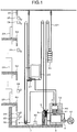
- Fig. 1 is a whole construction diagram showing an elevator of one embodiment, in which a car 20 moves through a plurality of floor s within a shaft constructed in a building, and is connected to a weight 22 via a rope 21.
- the movement of car 20 is made by a motor 9, and the motor 9 is supplied with electric power for driving by a power converter provided in an elevator controller 3.
- An encoder as a pulse generator is equipped to the motor 9 and the elevator controller 3 counts pulses generated by the rotation of the motor 9.
- the elevator controller 3 calculates the speed of motor 9, the position and the movement distance of car 20 along the direction of car movement and the like based on the count value of pulses to make a match between the car and the hatch.
- the car 20 is equipped with a car (cage) door which opens and closes in engagement with a hoistway door 23 and a position detecting sensor 27.
- a position detector is comprised of the position detecting sensor 27 and plates 50-54 to be detected as predetermined positions which are provided at a terminating floor, floors of intermediate floors and a floor side of the terminal portion, and identifies that the car 20 has arrived at the predetermined position.
- the position detecting sensor 27 detects a region (door zone) within which opening and closing of the hoistway door and the car door are permissible.
- the plate 51 to be detected at the lowermost floor, the plate 53 to be detected at the uppermost floor and the plate 52 to be detected at the intermediate floor are fixed to the respective floor surfaces.
- the plate 51 to be detected at the lowermost floor and the plate 53 to be detected at the uppermost floor have plate shapes different from that of the plate 52 to be detected at the intermediate floor, and the lowermost floor and the uppermost floor are made to be identifiable.
- the plates 50, 54 to be detected are provided which are capable of identifying the terminals.
- a governor 7 is wound with a governor rope connected with car 20 and rotates with movement of the car 20 to follow, and a governor encoder 8 equipped to the governor 7 detects the amount of revolution of the governor. Therefore, the governor encoder 8 generates pulses in accordance with the movement amount of the car 20.
- the outputs of the position detecting sensor 27 and the governor encoder 8 are inputted to the safety controller 2.
- the safety controller 2 is independent from the elevator controller 3, and outputs a power supply shutoff command or a braking command to stop the car 20 when the car reaches a predetermined position and thereafter is placed at another predetermined position.
- a first limit switch position 24 As mechanical switches a first limit switch position 24, a second limit switch position 25 and a third limit switch position 26 are provided. These positions are pre-stored and commands corresponding to the stored values are stored in the safety controller 2.
- the safety controller 2 In place of using the first limit switch position 24, the second limit switch position 25 and the third limit switch position 26, the safety controller 2 detects positions corresponding to those positions based on information from the position detecting sensor 27 and the governor encoder 8. The safety controller 2 outputs a signal 40 deciding the current car position to the elevator controller 3 if the current position of car 20 is in a defined condition. The safety controller 2 further outputs a position signal 41 indicating the current position of car 20 to the elevator controller 3.
- the governor encoder 8 may be replaced with an encoder equipped to the motor 9 or an encoder equipped to a guide roller of car 20, so that the governor rope may be dispensed with and the occupied space in the shaft may be reduced.
- Fig. 2 shows output patterns based on the position detecting sensor 27 required for detection of the terminating floor (on the car side) and shapes of the respective plates to be detected (on the floor side: 50, 51, 52, 53, 54).
- the position detecting sensor 27 is a three-axis sensor including a set of three sensors (sensor A, sensor B and sensor C).
- the plates to be detected are shaped so that either output of the sensors may be made OFF at the uppermost floor and the lowermost floor as terminating floors and the intermediate floor to thereby identify the terminating floor.
- the plates to be detected are shaped so that all sensor outputs may be made ON.
- the Figure shows that when any sensor of the position detecting sensor 27 opposes to a color painted portion of the plate to be detected the sensor output turns ON to be "1".
- sensor A, sensor B and sensor C output "1, 0, 1".
- the output at the intermediate floor is "1, 1, 0", and the output at the lowermost floor is "0, 1, 1".
- the size of plates to be detected in the vertical direction in the Figure corresponds to the length of the door zone.
- the sensor A, sensor B and sensor C output "1, 1, 1", and therefore, the size in the vertical direction corresponds to the same length as the region in which the conventional final limit switch functions.
- the safety controller 2 detects a combination of "1, 1, 1"
- power supply shutoff and brake operation are carried out as does the conventional final limit switch.
- the terminating floor may be identified as follows. A bar code is applied to only the terminating floor, and the applied bar code is read using a bar code reader provided to the car. Alternatively, a sensor capable of detecting a gap length against the plate to be detected may be used, where the gap length is made different between the intermediate floor and the terminating floor. The more the number of sensors increases the more floors can be identified, respectively.
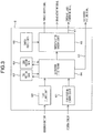
- Fig. 3 shows a block diagram regarding the function implemented by the safety controller. Basic operation of the respective blocks will be described as follows.
- a pulse counting unit 60 receives an input from the governor encoder 8, counts pulses corresponding to the movement amount of car 20, and outputs the counted value to a car position detecting unit 64.
- a floor position identifying unit 61 receives the output of position detecting sensor 27, identifies the current position of car 20 by an output pattern as shown in Fig. 2 , and outputs identification information of the car position.
- the car position detecting unit 64 based on the counted pulse value and identification information of the car position, outputs information of the current position of car 20 to a car position data 62 and a switch function executing unit 66.
- the car position data 62 stores the current position information as a history or log.
- the present data is preferably stored on mainly a RAM.
- a floor position data 63 data such as the distances between the respective floors and the distances between a buffer and the respective floors are stored, which the maintenance person pre-stores based on building design information.
- the present data are established on a ROM or a flash memory. When highly frequently updated the data may be established on RAM.
- the car position detecting unit 64 refers to the car position data 62, and stops the output of a car position deciding signal 40 when the car position information has not been stored (has not been memorized).
- the car position detecting unit 64 arithmetically operates the distance between floors every operation of the elevator, refers to the floor position data 63, and, for example, if the floor position data is different from the stored distance between the respective floors, outputs such a fact to the elevator controller.
- a switch position data 65 data corresponding to the positions in the shaft of electronic switches and the like are memorized and stored. These data are stored by maintenance person's inputting based on design information of the building or previously inputting when manufacturing the safety controller. These data are stored mainly on ROM or flash memory.
- a switch function executing unit 66 outputs a command for executing the function of the corresponding relevant switch when the current position of the car matches with the stored switch position data. For example, if the function of the relevant switch is a limit switch power shutoff or brake actuation is executed to stop or decelerate the car.
- the switch function executing unit 66 transmits information of the actuated switch function to the car controller 3.
- Fig. 4 shows transitions of states of from detection of car at the lowermost floor to arrival at the positions corresponding to a first limit switch 24 and a second limit switch 25 by three steps (a) to (c).
- the first floor IF is assumed as a reference floor.
- the number of pulses of the governor encoder for the descending direction of car in the shaft is assumed minus.
- the first limit switch is required for limiting the moving direction of the car. In its function, when the car reaches the position corresponding to the first limit switch only brake actuation is carried out and the car is permitted to move only in the ascending direction.
- the second limit switch is called "a final limit switch”. In its function, brake actuation and power shutoff are performed in order to prevent the car from colliding with a buffer 30 when car 20 reaches the second limit switch position.
- the safety controller 2 pre-stores the distances of from the plate 28 to be detected at the lowermost floor up to the first limit switch 24 and the second limit switch 25 (L1 and L1+L2, respectively) as data corresponding to the number of pulses outputted by the governor encoder 8 (L1 is -800 and L1+L2 is -1200 in Fig. 4 ).
- pre-stored switch position data 65 are provided in the safety controller as an initial setting. Therefore, the pre-stored value may be changed even in the restructure or reform.
- the maintenance person may input the pre-stored data directly to the safety controller through a data terminal. Alternatively, the pre-stored data may be inputted previously as an initial setting of the safety controller at the delivery. As a result, maintenance work such as data checking as well as arrangement work will be easy to do, so that the total cost can be reduced.
- Fig. 5 shows the case where a virtual limit switch is between the lowermost floor and the intermediate floor, and shows transitions of states of from detection of car at the lowermost floor up to arrival at the position corresponding to the third limit switch 26 by three steps (a) to (c).
- the function using the third limit switch is required for securing the uppermost space of elevator shaft when the maintenance person enters below a pit to work therein, and also is required for a terminating floor forced deceleration device for shortening the length of buffer 30 by early applying the brake in accordance with the position and the speed of car 20.
- the safety controller 2 pre-stores the distance (L3) of from the plate 28 to be detected at the lowermost floor 28 to the third limit switch 26 as data (L3 is 700 in Fig. 5 ) corresponding to the number of pulses outputted by the governor encoder 8.
- Column (a) indicates the state in which the position detecting sensor 27 has detected the plate 28 to be detected at the lowermost floor.
- the safety controller 2 discriminates that the car has arrived at the lowermost floor, and initializes the current position Lx to zero.
- the safety controller 2 in response to when car 20 ascends to cause the position detecting sensor 27 to pass through the plate 28 to be detected at the lowermost floor, the safety controller 2 starts counting of pulses outputted from the governor encoder 8 and calculates the relative distance from the plate 28 to be detected at the lowermost floor.
- the safety controller 2 compares the current position Lx of car 20 with the position L3 corresponding to the third limit switch and detects that both positions are coincident, so that the function of the third limit switch is carried out.
- FIG. 5 shows the case of the lowermost floor
- the like matter will be applied to the case of the uppermost floor as well.
- a more sophisticated functionality can be realized.
- Figs. 6 and 7 show operations when returned from power outage or a long-term unavailable state, and when returned from emergency stop.
- Fig. 6 shows the case where the car 20 is in the intermediate floor.
- Column (a) indicates the state in which a floor N of a reference position is unknown.
- the safety controller 2 is impossible to hold data of the safety controller 2, so that the reliability of position information of the floor N as the reference position and the current position Lx for car 20 is lowered.
- a backup battery may be provided to the controller 2 or the data themselves may be held in a flash memory.
- the safety controller 2 turns OFF a car position deciding signal 40 outputted to elevator controller 3 to signal to the elevator controller 3 that the current position of car 20 has not been decidable by the safety controller 2.
- the operation speed of car 20 is limited to start the descending operation slowly as shown in Fig. 6(b) .
- the safety controller 2 also monitors the operation speed of car, and when speed abnormality occurs, power shutoff and brake actuation will be performed to thereby stop the car.
- the safety controller 2 turns the car position deciding signal 40 ON, and initializes the current position Lx of car 20 to zero. Accordingly, the elevator controller 3 can restart the operation at the normal time.
- Fig. 7 shows the case where car 20 is below the terminating floor.
- the safety controller 2 turns OFF the position signal outputted to the elevator controller 3 (current position deciding signal) because of the car current position being unknown to signal that the current position of car 20 is undeterminable by the safety controller 2.
- the elevator controller 3 detects that the position signal 40 has been turned OFF, the operation speed of car 20 is limited and the descending operation starts slowly.
- the safety controller 2 monitors the operation speed of car as well, and when speed abnormality occurs, power shutoff and brake actuation will be carried out to stop the car.
- the safety controller 3 when the car arrives at the lowermost floor terminal portion as shown in Fig. 7(b) , and the safety controller 3 detects the arrival at the lowermost floor terminal portion through the position detecting sensor 27, the safety controller 2 effects power shutoff and brake actuation to stop the car. Subsequently, the car 20 is elevated, and when the safety controller 3 detects that the car has arrived at the lowermost floor through the position detecting sensor 27, the safety controller 2 turns the car position deciding signal 40 ON and initializes the current position Lx of car 20 to zero.
- the governor encoder 8 serving as a pulse generator for generating pulses in accordance with the movement amount of car
- the safety controller 2 receiving inputs from the position detecting sensor 27 and the pulse generator, deciding the current position by the safety controller 2, and outputting the car position deciding signal 40 to the elevator controller 3, it can be made to replace the safety system which has been conventionally mechanical, with electronic positions based on the safety controller, and identify the electronic positions to thereby implement the function of the safety system. Accordingly, the mechanical switches can be dispensed with, making it possible to improve the maintenance and effectively utilize the space of horizontal area in the shaft.
- Fig. 8 is the overall construction diagram showing an elevator according to another embodiment, in which a range sensor 70 is provided in the lower portion of a car, and plates 50, 54 to be detected at the lowermost floor terminal portion and at the uppermost floor terminal portion are not provided.
- the range sensor 70 may be capable of measuring the distance La indicated in Fig. 8 .
- Fig. 9 shows a block diagram of the function implemented by the safety controller 2, in which a terminating floor position measuring unit 67 is additionally added which outputs distance information provided by the range sensor 70 to the car position detecting unit 64.
- Fig. 10 shows the case where electronic switches are disposed below the terminating floor, in which the switches disposed below the terminating floor are made electronic (substituted for mechanical switches) based on information of the height from the shaft floor measured by the range sensor 70.
- the range sensor capable of measuring the region below the terminating floor it is possible to make electronic a plurality of switches disposed below the terminating floor even when returned from power outage or long-term inoperative state, thus making it possible to contribute to space saving and improve the operation speed when returned.
Claims (10)
- Ascenseur à sécurité électronique pour détecter la position d'une cabine (20) se déplaçant à travers une pluralité de planchers dans une cage, comprenant :un générateur d'impulsions qui sort des impulsions en accord avec l'amplitude de déplacement de ladite cabine (20) ; etun détecteur de position qui détecte que ladite cabine (20) arrive à une position prédéterminée,caractérisé parun contrôleur de sécurité (2) qui est configuré pour compter lesdites impulsions après que ladite position prédéterminée est détectée, et pour sortir un ordre correspondant à une valeur pré-stockée quand la valeur comptée atteint la valeur pré-stockée, dans lequel la valeur pré-stockée correspond à des positions stockées dans des données de position de commutateur (65) du contrôleur de sécurité (2) et les positions correspondant à un premier commutateur de limite virtuelle et à un second commutateur de limite virtuelle après détection d'un plancher terminal, et dans lequel l'ordre au niveau du premier commutateur de limite virtuelle est de limiter la direction de déplacement de la cabine (20) et, au niveau du second commutateur de limite virtuelle, d'actionner un freinage et de couper la puissance.
- Ascenseur à sécurité électronique selon la revendication 1, dans lequel ledit détecteur de position (27) détecte que ladite cabine (20) arrive audit plancher, et lesdites impulsions sont comptées après que ledit plancher est détecté.
- Ascenseur à sécurité électronique selon la revendication 1 ou 2, dans lequel lesdites impulsions sont comptées après que ladite cabine (20) arrive à un plancher terminal, et ladite cabine est décélérée ou arrêtée quand la valeur comptée atteint la valeur pré-stockée.
- Ascenseur à sécurité électronique selon l'une des revendications précédentes, dans lequel ledit détecteur de position (27) comprend un capteur de position prévu dans ladite cabine (20), et une plaque devant être détectée, qui est fixée sur le côté plancher dudit plancher terminal.
- Ascenseur à sécurité électronique sur l'une des revendications précédentes, dans lequel ledit détecteur de position (27) comprend un capteur de position prévu dans ladite cabine (20), et des plaques (50-54) devant être détectées, qui sont fixées sur les planchers respectifs et qui ont des longueurs correspondantes aux zones de porte.
- Ascenseur à sécurité électronique sur l'une des revendications précédentes, dans lequel
ledit détecteur de position (27) identifie la position de plancher via un capteur de détection de position prévu dans ladite cabine et des plaques (50-54) devant être détectées, qui sont fixées sur les planchers respectifs, et
ledit contrôleur de sécurité (2) comprend une unité de détection de position de cabine destinée à détecter la position actuelle de ladite cabine (20) sur la base de ladite valeur comptée d'impulsions et d'une information sur la position de plancher identifiée, d'une donnée de position de commutateur dans laquelle une donnée correspondant à des positions à l'intérieur de ladite cage sont stockées, et une unité d'exécution de fonction de commutateur répondant à une correspondance entre la position actuelle de ladite cabine et ladite donnée de position de commutateur pour sortir un ordre correspondant à une donnée en accord avec les positions à l'intérieur de la cage. - Ascenseur à sécurité électronique selon l'une des revendications précédentes, dans lequel ladite valeur pré-stockée est une valeur entrée précédemment.
- Ascenseur à sécurité électronique selon l'une des revendications précédentes, dans lequel, quand il revient d'une panne de courant ou d'un état de non-fonctionnement à long terme, ou quand il revient depuis un arrêt d'urgence, la valeur comptée est initialisée par ledit contrôleur de sécurité (2) quand ladite cabine (20) est amenée à descendre et que le plancher terminal est détecté.
- Ascenseur à sécurité électronique selon l'une des revendications précédentes, dans lequel une information de la position actuelle de ladite cabine (20) est stockée sur la base de ladite valeur comptée.
- Ascenseur à sécurité électronique selon l'une des revendications précédentes, dans lequel une donnée de position de cabine stockant la position actuelle de ladite cabine (20) sur la base de ladite valeur comptée est fournie, et la valeur comptée est initialisée par ledit contrôleur de sécurité (2) quand l'information de position de cabine n'est pas stockée ou quand ladite cabine (20) est amenée à descendre et que le plancher terminal est détecté.
Applications Claiming Priority (1)
| Application Number | Priority Date | Filing Date | Title |
|---|---|---|---|
| PCT/JP2010/003505 WO2011148411A1 (fr) | 2010-05-26 | 2010-05-26 | Ascenseur à sécurité électronique |
Publications (3)
| Publication Number | Publication Date |
|---|---|
| EP2578526A1 EP2578526A1 (fr) | 2013-04-10 |
| EP2578526A4 EP2578526A4 (fr) | 2016-08-03 |
| EP2578526B1 true EP2578526B1 (fr) | 2021-09-08 |
Family
ID=45003423
Family Applications (1)
| Application Number | Title | Priority Date | Filing Date |
|---|---|---|---|
| EP10852084.2A Active EP2578526B1 (fr) | 2010-05-26 | 2010-05-26 | Ascenseur à sécurité électronique |
Country Status (6)
| Country | Link |
|---|---|
| EP (1) | EP2578526B1 (fr) |
| JP (1) | JP5516727B2 (fr) |
| CN (1) | CN102869594B (fr) |
| HK (1) | HK1174603A1 (fr) |
| SG (1) | SG185682A1 (fr) |
| WO (1) | WO2011148411A1 (fr) |
Families Citing this family (24)
| Publication number | Priority date | Publication date | Assignee | Title |
|---|---|---|---|---|
| JP5607126B2 (ja) * | 2012-10-16 | 2014-10-15 | 株式会社Yutaka | エレベータ監視装置 |
| CN104936879B (zh) * | 2013-01-23 | 2017-04-19 | 三菱电机株式会社 | 电梯装置 |
| JP6190171B2 (ja) * | 2013-06-10 | 2017-08-30 | 株式会社日立製作所 | エレベータ |
| JP6317077B2 (ja) * | 2013-07-05 | 2018-04-25 | 株式会社日立製作所 | エレベーターの安全システム |
| JP6157962B2 (ja) * | 2013-07-17 | 2017-07-05 | 株式会社日立製作所 | エレベータ装置 |
| JP6207961B2 (ja) * | 2013-10-11 | 2017-10-04 | 株式会社日立製作所 | エレベータの安全システム |
| JP6187978B2 (ja) * | 2014-06-20 | 2017-08-30 | 株式会社日立ビルシステム | エレベーターの制御装置 |
| JP6362963B2 (ja) * | 2014-08-20 | 2018-07-25 | 株式会社日立製作所 | エレベーター装置 |
| CN104743414A (zh) * | 2015-03-19 | 2015-07-01 | 深圳市海浦蒙特科技有限公司 | 电梯运行控制方法及系统 |
| JP6549065B2 (ja) * | 2016-07-01 | 2019-07-24 | 株式会社日立製作所 | エレベーター装置及びプログラム |
| CN107804764A (zh) | 2016-09-09 | 2018-03-16 | 奥的斯电梯公司 | 电梯系统的位置识别和位置恢复 |
| JP2018104175A (ja) * | 2016-12-28 | 2018-07-05 | 株式会社日立製作所 | ガバナ装置およびエレベーター |
| EP3345852B1 (fr) * | 2017-01-09 | 2023-03-01 | KONE Corporation | Contrôleur de puissance |
| JP6641308B2 (ja) * | 2017-01-25 | 2020-02-05 | 株式会社日立製作所 | エレベーター |
| US10494228B2 (en) | 2017-02-28 | 2019-12-03 | Otis Elevator Company | Guiding devices for elevator systems having roller guides and motion sensors |
| CN107539857A (zh) * | 2017-08-30 | 2018-01-05 | 顺德职业技术学院 | 一种双稳态感应的教学实训电梯 |
| WO2020070795A1 (fr) * | 2018-10-02 | 2020-04-09 | 三菱電機株式会社 | Dispositif de commande de caractéristiques de système de limiteur de vitesse et dispositif d'ascenseur |
| CA3117772A1 (fr) * | 2018-12-20 | 2020-06-25 | Inventio Ag | Procede permettant de deplacer une cabine d'un ascenseur pour evacuer des passagers et dispositif d'ouverture de frein permettant de deplacer une cabine d'ascenseur pour evacuer d es passagers |
| JP7132438B2 (ja) * | 2019-07-02 | 2022-09-06 | 株式会社日立製作所 | エレベーター装置 |
| CN110422709B (zh) * | 2019-08-02 | 2022-04-08 | 上海三菱电梯有限公司 | 电梯楼层位置学习系统 |
| KR102265012B1 (ko) * | 2019-08-14 | 2021-06-15 | 현대엘리베이터주식회사 | 가변속도 엘리베이터의 강제 감속 제어장치 및 방법 |
| EP3848317A1 (fr) * | 2020-01-09 | 2021-07-14 | KONE Corporation | Système de sécurité d'ascenseur |
| CN111762645B (zh) * | 2020-07-28 | 2022-06-07 | 北京三快在线科技有限公司 | 电梯轿厢位置检测系统、方法及装置 |
| CN112623893B (zh) * | 2020-12-03 | 2023-04-14 | 深圳市普渡科技有限公司 | 一种电梯楼层确定方法、装置、计算机设备及存储介质 |
Family Cites Families (12)
| Publication number | Priority date | Publication date | Assignee | Title |
|---|---|---|---|---|
| US3750850A (en) * | 1972-05-17 | 1973-08-07 | Westinghouse Electric Corp | Floor selector for an elevator car |
| JPS5675367A (en) * | 1979-11-22 | 1981-06-22 | Hitachi Ltd | Method of controlling elevator |
| JPS5767475A (en) * | 1980-10-14 | 1982-04-24 | Hitachi Ltd | Method of generating deceleration command of elevator |
| US4515247A (en) * | 1984-02-09 | 1985-05-07 | Westinghouse Electric Corp. | Elevator system |
| JPS6194984A (ja) * | 1984-10-15 | 1986-05-13 | 三菱電機株式会社 | エレベ−タの位置制御装置 |
| FR2577329B1 (fr) * | 1985-02-12 | 1988-04-29 | Logilift Sarl | Procede de commande regulee d'un moteur electrique pour le deplacement d'un mobile et dispositif de commande pour la mise en oeuvre du procede |
| JPH05319726A (ja) * | 1992-05-13 | 1993-12-03 | Mitsubishi Electric Corp | エレベータの終端階減速装置 |
| CA2161291C (fr) * | 1994-11-18 | 2006-01-10 | Christian Arpagaus | Detecteur de vitesse excessive, utilisant plusieurs barrieres lumineuses |
| US5889239A (en) * | 1996-11-04 | 1999-03-30 | Otis Elevator Company | Method for monitoring elevator leveling performance with improved accuracy |
| JP2001322773A (ja) * | 2000-05-15 | 2001-11-20 | Toshiba Corp | エレベータの制御装置 |
| JP2007217136A (ja) * | 2006-02-17 | 2007-08-30 | Toshiba Elevator Co Ltd | エレベータ制御装置 |
| JP5140390B2 (ja) * | 2007-11-22 | 2013-02-06 | 株式会社日立製作所 | エレベーター制御システム |
-
2010
- 2010-05-26 EP EP10852084.2A patent/EP2578526B1/fr active Active
- 2010-05-26 JP JP2012516986A patent/JP5516727B2/ja active Active
- 2010-05-26 CN CN201080066528.9A patent/CN102869594B/zh active Active
- 2010-05-26 SG SG2012085528A patent/SG185682A1/en unknown
- 2010-05-26 WO PCT/JP2010/003505 patent/WO2011148411A1/fr active Application Filing
-
2013
- 2013-02-05 HK HK13101581.8A patent/HK1174603A1/zh unknown
Also Published As
| Publication number | Publication date |
|---|---|
| EP2578526A1 (fr) | 2013-04-10 |
| SG185682A1 (en) | 2013-01-30 |
| HK1174603A1 (zh) | 2013-06-14 |
| CN102869594B (zh) | 2015-11-25 |
| JPWO2011148411A1 (ja) | 2013-07-22 |
| CN102869594A (zh) | 2013-01-09 |
| WO2011148411A1 (fr) | 2011-12-01 |
| JP5516727B2 (ja) | 2014-06-11 |
| EP2578526A4 (fr) | 2016-08-03 |
Similar Documents
| Publication | Publication Date | Title |
|---|---|---|
| EP2578526B1 (fr) | Ascenseur à sécurité électronique | |
| US7201256B2 (en) | Elevator installation having a virtual protection area at the bottom and/or the top of the elevator shaft, and method for controlling the same | |
| CN110461748B (zh) | 多轿厢电梯系统和操作多轿厢电梯系统的方法 | |
| US7891467B2 (en) | Elevator safety arrangement having safety spaces | |
| EP2722300B1 (fr) | Dispositif de sécurité pour ascenseur | |
| US8261885B2 (en) | Safety arrangements for elevators and methods for monitoring safety of elevator systems | |
| US9676591B2 (en) | Elevator apparatus | |
| EP3366626B1 (fr) | Système de sécurité d'ascenseur et procédé de surveillance d'un système d'ascenseur | |
| JP5442679B2 (ja) | エレベーター用制御装置 | |
| US10947087B2 (en) | Elevator safety system and method of operating an elevator system | |
| EP3587323A1 (fr) | Système d'ascenseur | |
| CA1190676A (fr) | Systeme pour ascenseurs | |
| EP3878788A1 (fr) | Systèmes de sécurité d'ascenseur | |
| US20110240412A1 (en) | Elevator braking control | |
| US20220063955A1 (en) | Elevator systems |
Legal Events
| Date | Code | Title | Description |
|---|---|---|---|
| PUAI | Public reference made under article 153(3) epc to a published international application that has entered the european phase |
Free format text: ORIGINAL CODE: 0009012 |
|
| 17P | Request for examination filed |
Effective date: 20130102 |
|
| AK | Designated contracting states |
Kind code of ref document: A1 Designated state(s): AL AT BE BG CH CY CZ DE DK EE ES FI FR GB GR HR HU IE IS IT LI LT LU LV MC MK MT NL NO PL PT RO SE SI SK SM TR |
|
| DAX | Request for extension of the european patent (deleted) | ||
| RA4 | Supplementary search report drawn up and despatched (corrected) |
Effective date: 20160630 |
|
| RIC1 | Information provided on ipc code assigned before grant |
Ipc: B66B 5/06 20060101ALI20160624BHEP Ipc: B66B 5/10 20060101AFI20160624BHEP Ipc: B66B 1/34 20060101ALI20160624BHEP |
|
| STAA | Information on the status of an ep patent application or granted ep patent |
Free format text: STATUS: EXAMINATION IS IN PROGRESS |
|
| 17Q | First examination report despatched |
Effective date: 20170324 |
|
| STAA | Information on the status of an ep patent application or granted ep patent |
Free format text: STATUS: EXAMINATION IS IN PROGRESS |
|
| GRAP | Despatch of communication of intention to grant a patent |
Free format text: ORIGINAL CODE: EPIDOSNIGR1 |
|
| STAA | Information on the status of an ep patent application or granted ep patent |
Free format text: STATUS: GRANT OF PATENT IS INTENDED |
|
| INTG | Intention to grant announced |
Effective date: 20210503 |
|
| GRAS | Grant fee paid |
Free format text: ORIGINAL CODE: EPIDOSNIGR3 |
|
| GRAA | (expected) grant |
Free format text: ORIGINAL CODE: 0009210 |
|
| STAA | Information on the status of an ep patent application or granted ep patent |
Free format text: STATUS: THE PATENT HAS BEEN GRANTED |
|
| RIN1 | Information on inventor provided before grant (corrected) |
Inventor name: YOSHIKAWA, TOSHIFUMI Inventor name: OKAMURA, KIYOSHI Inventor name: FUKATA, HIRONORI Inventor name: FURUHASHI, MASAYA Inventor name: INOUE, SHINSUKE |
|
| AK | Designated contracting states |
Kind code of ref document: B1 Designated state(s): AL AT BE BG CH CY CZ DE DK EE ES FI FR GB GR HR HU IE IS IT LI LT LU LV MC MK MT NL NO PL PT RO SE SI SK SM TR |
|
| REG | Reference to a national code |
Ref country code: GB Ref legal event code: FG4D |
|
| REG | Reference to a national code |
Ref country code: CH Ref legal event code: EP Ref country code: AT Ref legal event code: REF Ref document number: 1428429 Country of ref document: AT Kind code of ref document: T Effective date: 20210915 |
|
| REG | Reference to a national code |
Ref country code: DE Ref legal event code: R096 Ref document number: 602010067572 Country of ref document: DE |
|
| REG | Reference to a national code |
Ref country code: IE Ref legal event code: FG4D |
|
| REG | Reference to a national code |
Ref country code: LT Ref legal event code: MG9D |
|
| REG | Reference to a national code |
Ref country code: NL Ref legal event code: MP Effective date: 20210908 |
|
| PG25 | Lapsed in a contracting state [announced via postgrant information from national office to epo] |
Ref country code: HR Free format text: LAPSE BECAUSE OF FAILURE TO SUBMIT A TRANSLATION OF THE DESCRIPTION OR TO PAY THE FEE WITHIN THE PRESCRIBED TIME-LIMIT Effective date: 20210908 Ref country code: SE Free format text: LAPSE BECAUSE OF FAILURE TO SUBMIT A TRANSLATION OF THE DESCRIPTION OR TO PAY THE FEE WITHIN THE PRESCRIBED TIME-LIMIT Effective date: 20210908 Ref country code: BG Free format text: LAPSE BECAUSE OF FAILURE TO SUBMIT A TRANSLATION OF THE DESCRIPTION OR TO PAY THE FEE WITHIN THE PRESCRIBED TIME-LIMIT Effective date: 20211208 Ref country code: LT Free format text: LAPSE BECAUSE OF FAILURE TO SUBMIT A TRANSLATION OF THE DESCRIPTION OR TO PAY THE FEE WITHIN THE PRESCRIBED TIME-LIMIT Effective date: 20210908 Ref country code: NO Free format text: LAPSE BECAUSE OF FAILURE TO SUBMIT A TRANSLATION OF THE DESCRIPTION OR TO PAY THE FEE WITHIN THE PRESCRIBED TIME-LIMIT Effective date: 20211208 Ref country code: ES Free format text: LAPSE BECAUSE OF FAILURE TO SUBMIT A TRANSLATION OF THE DESCRIPTION OR TO PAY THE FEE WITHIN THE PRESCRIBED TIME-LIMIT Effective date: 20210908 Ref country code: FI Free format text: LAPSE BECAUSE OF FAILURE TO SUBMIT A TRANSLATION OF THE DESCRIPTION OR TO PAY THE FEE WITHIN THE PRESCRIBED TIME-LIMIT Effective date: 20210908 |
|
| REG | Reference to a national code |
Ref country code: AT Ref legal event code: MK05 Ref document number: 1428429 Country of ref document: AT Kind code of ref document: T Effective date: 20210908 |
|
| PG25 | Lapsed in a contracting state [announced via postgrant information from national office to epo] |
Ref country code: LV Free format text: LAPSE BECAUSE OF FAILURE TO SUBMIT A TRANSLATION OF THE DESCRIPTION OR TO PAY THE FEE WITHIN THE PRESCRIBED TIME-LIMIT Effective date: 20210908 Ref country code: GR Free format text: LAPSE BECAUSE OF FAILURE TO SUBMIT A TRANSLATION OF THE DESCRIPTION OR TO PAY THE FEE WITHIN THE PRESCRIBED TIME-LIMIT Effective date: 20211209 |
|
| PG25 | Lapsed in a contracting state [announced via postgrant information from national office to epo] |
Ref country code: AT Free format text: LAPSE BECAUSE OF FAILURE TO SUBMIT A TRANSLATION OF THE DESCRIPTION OR TO PAY THE FEE WITHIN THE PRESCRIBED TIME-LIMIT Effective date: 20210908 |
|
| PG25 | Lapsed in a contracting state [announced via postgrant information from national office to epo] |
Ref country code: IS Free format text: LAPSE BECAUSE OF FAILURE TO SUBMIT A TRANSLATION OF THE DESCRIPTION OR TO PAY THE FEE WITHIN THE PRESCRIBED TIME-LIMIT Effective date: 20220108 Ref country code: SM Free format text: LAPSE BECAUSE OF FAILURE TO SUBMIT A TRANSLATION OF THE DESCRIPTION OR TO PAY THE FEE WITHIN THE PRESCRIBED TIME-LIMIT Effective date: 20210908 Ref country code: SK Free format text: LAPSE BECAUSE OF FAILURE TO SUBMIT A TRANSLATION OF THE DESCRIPTION OR TO PAY THE FEE WITHIN THE PRESCRIBED TIME-LIMIT Effective date: 20210908 Ref country code: RO Free format text: LAPSE BECAUSE OF FAILURE TO SUBMIT A TRANSLATION OF THE DESCRIPTION OR TO PAY THE FEE WITHIN THE PRESCRIBED TIME-LIMIT Effective date: 20210908 Ref country code: PT Free format text: LAPSE BECAUSE OF FAILURE TO SUBMIT A TRANSLATION OF THE DESCRIPTION OR TO PAY THE FEE WITHIN THE PRESCRIBED TIME-LIMIT Effective date: 20220110 Ref country code: PL Free format text: LAPSE BECAUSE OF FAILURE TO SUBMIT A TRANSLATION OF THE DESCRIPTION OR TO PAY THE FEE WITHIN THE PRESCRIBED TIME-LIMIT Effective date: 20210908 Ref country code: NL Free format text: LAPSE BECAUSE OF FAILURE TO SUBMIT A TRANSLATION OF THE DESCRIPTION OR TO PAY THE FEE WITHIN THE PRESCRIBED TIME-LIMIT Effective date: 20210908 Ref country code: EE Free format text: LAPSE BECAUSE OF FAILURE TO SUBMIT A TRANSLATION OF THE DESCRIPTION OR TO PAY THE FEE WITHIN THE PRESCRIBED TIME-LIMIT Effective date: 20210908 Ref country code: CZ Free format text: LAPSE BECAUSE OF FAILURE TO SUBMIT A TRANSLATION OF THE DESCRIPTION OR TO PAY THE FEE WITHIN THE PRESCRIBED TIME-LIMIT Effective date: 20210908 Ref country code: AL Free format text: LAPSE BECAUSE OF FAILURE TO SUBMIT A TRANSLATION OF THE DESCRIPTION OR TO PAY THE FEE WITHIN THE PRESCRIBED TIME-LIMIT Effective date: 20210908 |
|
| REG | Reference to a national code |
Ref country code: DE Ref legal event code: R097 Ref document number: 602010067572 Country of ref document: DE |
|
| PLBE | No opposition filed within time limit |
Free format text: ORIGINAL CODE: 0009261 |
|
| STAA | Information on the status of an ep patent application or granted ep patent |
Free format text: STATUS: NO OPPOSITION FILED WITHIN TIME LIMIT |
|
| PG25 | Lapsed in a contracting state [announced via postgrant information from national office to epo] |
Ref country code: DK Free format text: LAPSE BECAUSE OF FAILURE TO SUBMIT A TRANSLATION OF THE DESCRIPTION OR TO PAY THE FEE WITHIN THE PRESCRIBED TIME-LIMIT Effective date: 20210908 |
|
| 26N | No opposition filed |
Effective date: 20220609 |
|
| PG25 | Lapsed in a contracting state [announced via postgrant information from national office to epo] |
Ref country code: SI Free format text: LAPSE BECAUSE OF FAILURE TO SUBMIT A TRANSLATION OF THE DESCRIPTION OR TO PAY THE FEE WITHIN THE PRESCRIBED TIME-LIMIT Effective date: 20210908 |
|
| REG | Reference to a national code |
Ref country code: CH Ref legal event code: PL |
|
| REG | Reference to a national code |
Ref country code: BE Ref legal event code: MM Effective date: 20220531 |
|
| GBPC | Gb: european patent ceased through non-payment of renewal fee |
Effective date: 20220526 |
|
| PG25 | Lapsed in a contracting state [announced via postgrant information from national office to epo] |
Ref country code: MC Free format text: LAPSE BECAUSE OF FAILURE TO SUBMIT A TRANSLATION OF THE DESCRIPTION OR TO PAY THE FEE WITHIN THE PRESCRIBED TIME-LIMIT Effective date: 20210908 Ref country code: LU Free format text: LAPSE BECAUSE OF NON-PAYMENT OF DUE FEES Effective date: 20220526 Ref country code: LI Free format text: LAPSE BECAUSE OF NON-PAYMENT OF DUE FEES Effective date: 20220531 Ref country code: IT Free format text: LAPSE BECAUSE OF FAILURE TO SUBMIT A TRANSLATION OF THE DESCRIPTION OR TO PAY THE FEE WITHIN THE PRESCRIBED TIME-LIMIT Effective date: 20210908 Ref country code: CH Free format text: LAPSE BECAUSE OF NON-PAYMENT OF DUE FEES Effective date: 20220531 |
|
| REG | Reference to a national code |
Ref country code: FR Ref legal event code: PLFP Year of fee payment: 14 |
|
| PG25 | Lapsed in a contracting state [announced via postgrant information from national office to epo] |
Ref country code: IE Free format text: LAPSE BECAUSE OF NON-PAYMENT OF DUE FEES Effective date: 20220526 |
|
| PG25 | Lapsed in a contracting state [announced via postgrant information from national office to epo] |
Ref country code: GB Free format text: LAPSE BECAUSE OF NON-PAYMENT OF DUE FEES Effective date: 20220526 Ref country code: BE Free format text: LAPSE BECAUSE OF NON-PAYMENT OF DUE FEES Effective date: 20220531 |
|
| PGFP | Annual fee paid to national office [announced via postgrant information from national office to epo] |
Ref country code: FR Payment date: 20230411 Year of fee payment: 14 Ref country code: DE Payment date: 20230331 Year of fee payment: 14 |
|
| PG25 | Lapsed in a contracting state [announced via postgrant information from national office to epo] |
Ref country code: HU Free format text: LAPSE BECAUSE OF FAILURE TO SUBMIT A TRANSLATION OF THE DESCRIPTION OR TO PAY THE FEE WITHIN THE PRESCRIBED TIME-LIMIT; INVALID AB INITIO Effective date: 20100526 |