EP2578364A2 - Robot system - Google Patents
Robot system Download PDFInfo
- Publication number
- EP2578364A2 EP2578364A2 EP12156108.8A EP12156108A EP2578364A2 EP 2578364 A2 EP2578364 A2 EP 2578364A2 EP 12156108 A EP12156108 A EP 12156108A EP 2578364 A2 EP2578364 A2 EP 2578364A2
- Authority
- EP
- European Patent Office
- Prior art keywords
- unit
- robot
- horizontal arm
- base
- arm unit
- Prior art date
- Legal status (The legal status is an assumption and is not a legal conclusion. Google has not performed a legal analysis and makes no representation as to the accuracy of the status listed.)
- Withdrawn
Links
Images



Classifications
-
- B—PERFORMING OPERATIONS; TRANSPORTING
- B25—HAND TOOLS; PORTABLE POWER-DRIVEN TOOLS; MANIPULATORS
- B25J—MANIPULATORS; CHAMBERS PROVIDED WITH MANIPULATION DEVICES
- B25J9/00—Program-controlled manipulators
- B25J9/02—Program-controlled manipulators characterised by movement of the arms, e.g. cartesian coordinate type
- B25J9/04—Program-controlled manipulators characterised by movement of the arms, e.g. cartesian coordinate type by rotating at least one arm, excluding the head movement itself, e.g. cylindrical coordinate type or polar coordinate type
- B25J9/041—Cylindrical coordinate type
- B25J9/042—Cylindrical coordinate type comprising an articulated arm
-
- B—PERFORMING OPERATIONS; TRANSPORTING
- B25—HAND TOOLS; PORTABLE POWER-DRIVEN TOOLS; MANIPULATORS
- B25J—MANIPULATORS; CHAMBERS PROVIDED WITH MANIPULATION DEVICES
- B25J19/00—Accessories fitted to manipulators, e.g. for monitoring, for viewing; Safety devices combined with or specially adapted for use in connection with manipulators
- B25J19/0066—Means or methods for maintaining or repairing manipulators
-
- B—PERFORMING OPERATIONS; TRANSPORTING
- B25—HAND TOOLS; PORTABLE POWER-DRIVEN TOOLS; MANIPULATORS
- B25J—MANIPULATORS; CHAMBERS PROVIDED WITH MANIPULATION DEVICES
- B25J5/00—Manipulators mounted on wheels or on carriages
- B25J5/02—Manipulators mounted on wheels or on carriages travelling along a guideway
-
- B—PERFORMING OPERATIONS; TRANSPORTING
- B25—HAND TOOLS; PORTABLE POWER-DRIVEN TOOLS; MANIPULATORS
- B25J—MANIPULATORS; CHAMBERS PROVIDED WITH MANIPULATION DEVICES
- B25J9/00—Program-controlled manipulators
- B25J9/02—Program-controlled manipulators characterised by movement of the arms, e.g. cartesian coordinate type
- B25J9/04—Program-controlled manipulators characterised by movement of the arms, e.g. cartesian coordinate type by rotating at least one arm, excluding the head movement itself, e.g. cylindrical coordinate type or polar coordinate type
- B25J9/046—Revolute coordinate type
-
- H—ELECTRICITY
- H10—SEMICONDUCTOR DEVICES; ELECTRIC SOLID-STATE DEVICES NOT OTHERWISE PROVIDED FOR
- H10P—GENERIC PROCESSES OR APPARATUS FOR THE MANUFACTURE OR TREATMENT OF DEVICES COVERED BY CLASS H10
- H10P72/00—Handling or holding of wafers, substrates or devices during manufacture or treatment thereof
- H10P72/30—Handling or holding of wafers, substrates or devices during manufacture or treatment thereof for conveying, e.g. between different workstations
- H10P72/33—Handling or holding of wafers, substrates or devices during manufacture or treatment thereof for conveying, e.g. between different workstations into and out of processing chamber
- H10P72/3302—Mechanical parts of transfer devices
-
- H—ELECTRICITY
- H10—SEMICONDUCTOR DEVICES; ELECTRIC SOLID-STATE DEVICES NOT OTHERWISE PROVIDED FOR
- H10P—GENERIC PROCESSES OR APPARATUS FOR THE MANUFACTURE OR TREATMENT OF DEVICES COVERED BY CLASS H10
- H10P72/00—Handling or holding of wafers, substrates or devices during manufacture or treatment thereof
- H10P72/70—Handling or holding of wafers, substrates or devices during manufacture or treatment thereof for supporting or gripping
- H10P72/76—Handling or holding of wafers, substrates or devices during manufacture or treatment thereof for supporting or gripping using mechanical means, e.g. clamps or pinches
- H10P72/7602—Handling or holding of wafers, substrates or devices during manufacture or treatment thereof for supporting or gripping using mechanical means, e.g. clamps or pinches the wafers being placed on a robot blade or gripped by a gripper for conveyance
Definitions
- Patent Document 1 proposes a robot that vertically moves by moving a leg unit and conveys a thin-plate like work, such as a semiconductor wafer, by an arm unit arranged in the upper portion.
- Examples of documents related to the above-described conventional technology include Japanese Patent No. 4466785 .
- An aspect of embodiments is achieved in view of the above and an object thereof is to provide a robot system capable of reducing the time required for the maintenance operation.
- a robot system includes a robot and a control unit.
- the robot includes a plurality of movable units that operate in a predetermined direction and links connected to the movable units, and the control unit controls an operation of the movable units of the robot.
- the robot system transfers a detachable member mounted on a predetermined movable unit by causing a movable unit other than the predetermined movable unit to operate in a state where the predetermined movable unit is stopped.
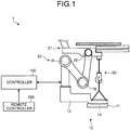
- FIG. 1 is an explanatory diagram of a robot system according to a first embodiment
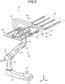
- FIG. 2 is a schematic perspective view of a robot according to the first embodiment
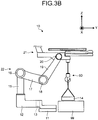
- FIG. 3A and FIG. 3B are schematic front views of the robot according to the first embodiment
- FIG. 4A , FIG. 4B , and FIG. 4C are schematic front views of a robot according to a second embodiment
- FIG. 5A , FIG. 5B , FIG. 5C , and FIG. 5D are schematic front views of a robot according to a third embodiment.
- FIG. 6A and FIG. 6B are schematic front views of a robot according to a fourth embodiment.
- FIG. 1 is an explanatory diagram of the robot system 1 according to the first embodiment.
- the shape is partially simplified to make the explanation easy.
- the robot system 1 includes a robot 10, a controller 100, and a remote controller 200.
- the robot 10 and the controller 100 are connected and the controller 100 and the remote controller 200 are connected.
- the robot 10, the controller 100, and the remote controller 200 may be connected to each other by cables or may be capable of communicating with each other wirelessly.
- the robot 10 is an industrial robot called manipulator.
- the robot 10 performs an operation, such as gripping and transfer of a work, by generating a program (hereinafter, described as "teaching") for moving the robot 10 by the remote controller 200 or the controller 100 and reproducing the taught teaching data.
- a program hereinafter, described as "teaching"
- the robot 10 is configured to include one leg unit.
- the leg unit is a part that includes a base part 12 and a lift mechanism 22 and supports a horizontal arm unit 21.
- the robot 10 includes a base 11, the base part 12, a speed reducer 14, the lift mechanism 22, and the horizontal arm unit 21, and the lift mechanism 22 includes a first joint 16, a second joint 18, a third joint 20, a first link 17, and a second link 19.
- the robot 10 raises and lowers the horizontal arm unit 21 in a vertical direction by driving an actuator and a motor (not shown) built in the first joint 16, the second joint 18, and the third joint 20. Details of the shape of the robot 10 and the operation of the horizontal arm unit 21 are described later with reference to FIG. 2 .
- the controller 100 is a control apparatus that controls an operation such as start and stop of the robot 10.
- the controller 100 can perform teaching and reproduction of teaching data.
- the remote controller 200 is generally called teaching pendant and is an input/output terminal of the controller 100.
- the remote controller 200 is a portable operation device for teaching.
- the remote controller 200 reproduces teaching data recorded by teaching via the controller 100 and causes the robot 10 to perform a series of operations.
- the remote controller 200 is composed of various switches and buttons, and the like and includes an operating unit for performing an operation such as teaching and a display unit that displays teaching data in teaching, a control state of the robot 10, and the like.
- the robot 10 when performing an operation such as gripping and transfer of a work, the robot 10 performs an operation such as gripping and transfer of a work as instructed by the taught teaching data.
- a robot system when performing the maintenance operation of a robot, performs the operation after stopping the robot or turning off the power by a controller.
- the operation in the case of the maintenance operation of, for example, replacing a heavy part such as a motor included in the robot, the operation needs to be performed by using heavy machinery such as a crane. Therefore, it takes time to prepare heavy machinery and perform an actual operation.
- the movable units may include a joint, and an actuator and a motor as a driving source or include only a driving source.
- the robot system 1 can raise and lower the horizontal arm unit 21 of the robot 10 in the vertical direction by an operator operating a handle, a lever, and the like of the remote controller 200.
- a detachable lifting jig 50 is mounted on the lower surface of the horizontal arm unit 21.
- a case of replacing the speed reducer 14 as a heavy part arranged in the base part 12 is explained.
- the robot system 1 raises and lowers the lifting jig 50 by causing the horizontal arm unit 21 to operate in the vertical direction, thereby lifting and transferring the speed reducer 14 arranged in the base part 12. With such an operation, in the robot system 1 according to the first embodiment, heavy machinery such as a crane is not needed, so that the time required for the maintenance operation can be reduced.
- FIG. 2 is a schematic perspective view of the robot 10 according to the first embodiment.
- a Z axis direction is the vertical direction.
- the robot 10 includes the base 11, the base part 12, the lift mechanism 22, and the horizontal arm unit 21, and the lift mechanism 22 includes a supporting column 15, the first joint 16, the second joint 18, the third joint 20, the first link 17, and the second link 19.
- the base part 12 includes an approximately disk-shaped pivot portion pivotally attached to the base 11 and an extension portion extending from one end of the pivot portion in a horizontal direction, and pivots around a pivot o1, which is vertical to the base 11, by driving the speed reducer 14. Then, the lift mechanism 22 and the horizontal arm unit 21 revolve around the pivot 01 with the pivoting of the base part 12.
- the supporting column 15 is set up in the vertical direction from the tip end of the base part 12.
- the first link 17 is connected to the tip end of the supporting column 15 at the base end via the first joint 16. Therefore, the first link 17 is supported at the tip end of the supporting column 15 to be rotatable around a joint axis 02 of the first joint 16 that is an axis parallel to the X axis.
- the second link 19 is connected to the tip end of the first link 17 at the base end via the second joint 18. Therefore, the second link 19 is supported at the tip end of the first link 17 to be rotatable around a joint axis 03 of the second joint 18 that is an axis parallel to the X axis.
- the horizontal arm unit 21 is connected to the tip end of the second link 19 via the third joint 20. Therefore, the horizontal arm unit 21 is supported at the tip end of the second link 19 to be rotatable around a joint axis 04 of the third joint 20 that is an axis parallel to the X axis.
- the lift mechanism 22 causes each of the first joint 16, the second joint 18, and the third joint 20 to operate by a not-shown actuator. Consequently, the lift mechanism 22 raises and lowers the horizontal arm unit 21 in the vertical direction (Z axis direction) by changing the attitude of the first link 17 and the second link 19. In this manner, in the robot 10 according to the first embodiment, the horizontal arm unit 21 is supported by one lift mechanism 22.
- the horizontal arm unit 21 includes a lower arm unit 31a and an upper arm unit 31b.
- the lower arm unit 31a and the upper arm unit 31b haves a similar configuration, so that only the lower arm unit 31a is explained.
- the lower arm unit 31a includes a hand part 33 for placing a work W as an object to be conveyed, an arm part 32 that supports the hand part 33 at the tip end, and a lower support member 34.
- the lower support member 34 is supported at the tip end of the second link 19 to be rotatable around the joint axis 04 of the third joint 20.
- the arm part 32 includes a base end side arm 35 and a tip end side arm 36.
- the base end side arm 35 is supported by the lower support member 34 to be rotatable around the joint axis of a joint 37.
- the tip end side arm 36 is supported at the tip end of the base end side arm 35 to be rotatable around the joint axis of a joint 38.
- the hand part 33 is rotatably supported at the tip end of the tip end side arm 36.
- the arm part 32 extends and retracts by a rotation operation of the base end side arm 35 and the tip end side arm 36, whereby the hand part 33 linearly moves in the X axis direction.
- the hand part 33 on which the work W is to be placed is moved in a direction parallel to the joint axis 03 on the pivot o1 side with respect to the supporting column 15.
- the X axis direction is a moving direction of the hand part 33 and extension and retraction directions of the arm part 32.
- the horizontal arm unit 21 includes the lower arm unit 31a and the upper arm unit 31b however, for example, the horizontal arm unit 21 may be configured without providing the upper arm unit 31b.
- FIG. 3A is a first schematic front view of the robot 10 according to the first embodiment
- FIG. 3B is a second schematic front view of the robot 10 according to the first embodiment.
- explanation is given by appropriately using the coordinate axes as shown in the upper right in FIG. 3A and FIG. 3B .
- the upper arm unit 31b in the horizontal arm unit 21 has a configuration similar to the lower arm unit 31a, so that the upper arm unit 31b is omitted in FIG. 3A and FIG. 3B .
- the lifting jig 50 is mounted on the lower side of the horizontal arm unit 21 and the speed reducer 14 arranged in the base part 12 is lifted by the lifting jig 50.
- the robot 10 includes the base 11, the base part 12, a pivoting motor 13, the speed reducer 14, the lift mechanism 22, and the horizontal arm unit 21, and the lift mechanism 22 includes the supporting column 15, the first joint 16, the second joint 18, the third joint 20, the first link 17, and the second link 19. Moreover, a work station 99 for performing a replacing operation of the speed reducer 14 is arranged on the positive direction side of the Y axis of the base 11.
- the pivoting motor 13 is a driving source of the pivot mechanism arranged in the base part 12, and the driving force of the pivoting motor 13 is transmitted to the speed reducer 14 via a not-shown belt.
- the output shaft of the speed reducer 14 is fixed to the base 11 and the base part 12 pivots around a pivot parallel to the Z axis by driving the speed reducer 14.
- the robot system 1 In the maintenance operation of the robot 10, for example, when replacing the speed reducer 14, the robot system 1 causes only the lift mechanism 22 as one of the movable units to operate and keeps other movable units including the pivoting motor 13 and the like stopped.
- the robot system 1 rotates the first link 17 and the second link 19 by driving an actuator and a motor (not shown) built in the first joint 16 and the second joint 18. Consequently, the horizontal arm unit 21 is raised and lowered along the pivot 01.
- the lifting jig 50 is detachable from the lower surface of the horizontal arm unit 21 on the extension of the pivot o1. Because the pivot o1 and the third joint 20 are located at positions that do not intersect each other, the first link 17 and the second link 19 do not obstruct the lifting jig 50 and the rope of the lifting jig 50.
- the lifting jig 50 is raised by a normal operation, that is, a lift control same as the operation when performing gripping and transfer of a work, whereby the detachable speed reducer 14 can be lifted in the vertical direction.
- the horizontal arm unit 21 of the robot 10 is raised and lowered in the vertical direction by an operator operating a handle, a lever, and the like included in the remote controller 200.
- the robot system 1 further causes the lift mechanism 22 to operate to move the horizontal arm unit 21 in the positive direction of the Y axis as shown in FIG. 3B , thereby transferring the speed reducer 14 to the work station 99 for performing a replacing operation of the speed reducer 14.
- the horizontal arm unit 21 is moved in the vertical direction and the positive direction of the Y axis by causing the lift mechanism 22 to operate, however, it is not limited thereto.
- a slide mechanism which linearly moves in the Y axis direction or the X axis direction, may be provided in the upper portion of the lifting jig 50.
- the robot system 1 can raise and lower the horizontal arm unit 21 in the vertical direction by the lift mechanism 22 and moreover, move the lifting jig 50 in the horizontal direction by the slide mechanism included in the lifting jig 50.
- the lifting jig 50 may be mounted on the hand part 33 for placing the work W, and with this configuration, the robot system 1 can move the lifting jig 50 in the vertical direction and a direction parallel to the joint axis 03 with respect to the supporting column 15.
- the robot system transfers a heavy part by causing only part of the movable units included in the robot to operate. Consequently, the robot system according to the first embodiment does not need heavy machinery such as a crane and thus can reduce the time required for the maintenance operation.
- the lift mechanism included in the robot includes a plurality of joints and links.
- a lift mechanism composed of different members may be used.
- FIG. 4A to FIG. 4C are first to third schematic front views of a robot 10A according to the second embodiment.
- a lift mechanism 310 included in the robot 10A according to the second embodiment travels in the vertical direction while being guided by a guide rail, which is different from the first embodiment.
- the configuration of a horizontal arm unit 304 is similar to FIG. 2 , so that explanation of the configuration thereof is omitted here.
- the robot 10A includes a base 301, a base part 302, a speed reducer 303, the lift mechanism 310, and the horizontal arm unit 304, and the lift mechanism 310 includes a supporting column 311, a vertical driving unit 305, and a rail part 306.
- the base part 302 includes an approximately disk-shaped pivot portion pivotally attached to the base 301 and an extension portion extending from one end of the pivot portion in the horizontal direction.
- the extension portion side of the base part 302 is fixed to the lower portion of the supporting column 311.
- the speed reducer 303 is arranged in the base 301 or the pivot portion side in the base part 302, and the base part 302 pivots around a pivot 05 vertical to the base 301 by the speed reducer 303.
- the supporting column 311 revolves around the pivot 05 with the pivoting of the base part 302, however, the supporting column 311 revolves at a position distance from the center by the length of the base part 302.
- the vertical driving unit 305 slides in the vertical direction (Z axis direction) along the rail part 306 arranged parallel to the supporting column 311 by causing the vertical driving unit 305 to operate by a not-shown actuator.
- the horizontal arm unit 304 connected to the vertical driving unit 305 is raised and lowered in the vertical direction along the supporting column 311 above the base 301.
- the vertical driving unit 305 and the horizontal arm unit 304 are detachable.
- the horizontal arm unit 304 is fixed by a fall preventing jig 307, and a lifting jig 308 is mounted on the vertical driving unit 305 included in the lift mechanism 310.
- a jig arm 309 prepared in advance for maintenance is connected to the vertical driving unit 305 and moreover, the lifting jig 308 is mounted on the jig arm 309 in a state where the hook of the lifting jig 308 is located on the extension of the pivot 05.
- the jig arm 309 can extend and retract in the horizontal direction (Y axis direction).
- the robot system transfers the speed reducer 303 by extending and retracting the jig arm 309 in the Y axis direction. In this manner, in robot system, the operation is performed while reducing a loaded on the motor built in the vertical driving unit 305 by temporarily separating the horizontal arm unit 304.
- the jig arm 309 and the speed reducer 303 are composed of members with which the total weight of the jig arm 309 and the speed reducer 303 becomes lighter than the horizontal arm unit 304. Therefore, it is sufficient that the motor built in the vertical driving unit 305 has a capacity enough to move the horizontal arm unit 304 and a load when lifting the speed reducer 303 does not need to be considered.
- the jig arm 309 is separated from the robot and is configured to be connected to the vertical driving unit 305 in the case of the "maintenance mode".
- the configuration may be such that the horizontal arm unit 304 excluding the arm is separated in a state where the arm included in the horizontal arm unit 304 is connected to the vertical driving unit 305.
- the horizontal arm unit 304 is temporarily separated and the jig arm 309 and the lifting jig 308 are mounted, however, it is not limited thereto.
- the detachable lifting jig 308 may be directly mounted on the horizontal arm unit 304 in a state where the horizontal arm unit 304 is connected to the vertical driving unit 305.
- the lifting jig 308 is mounted on the horizontal arm unit 304 in a state where the hook of the lifting jig 308 is located on the extension of the pivot 05. Then, the vertical driving unit 305 raises the lifting jig 308 to lift the detachable speed reducer 303 in the vertical direction.
- the robot system transfers a heavy part by activating only part of the movable units included in the robot. Moreover, it is possible to operate by attaching an arm, on which the lifting jig is directly mounted, to the lift mechanism so that the lifting jig is movable in the horizontal direction (Y axis direction). With this configuration, in the robot system according to the second embodiment, heavy machinery such as a crane is not needed, so that the time required for the maintenance operation can be reduced.
- the robot 10B according to the third embodiment includes a travel mechanism 39, which is different from the robots 10 and 10A in the first and second embodiments.
- FIG. 5A to FIG. 5D are first to fourth schematic front views of the robot 10B according to the third embodiment.
- the robot 10B according to the third embodiment includes the travel mechanism 39.
- the robot 10B has a configuration similar to the robot 10 in the first embodiment except for the configuration of a base 11B, so that, in this embodiment, only the different configuration is explained.
- the base 11B and the base part 12 pivot around the pivot 01 vertical to the base 11B by driving the driving source of a not-shown pivot mechanism. Then, with the pivoting of the base part 12, the lift mechanism 22 and the horizontal arm unit 21 revolve around the pivot o1.
- the travel mechanism 39 is provided with a rack gear 42 extending along the Y axis direction.
- a travelling unit 40 is connected to the lower portion of the base 11B and the base 11B and the travelling unit 40 are detachable.
- a travelling motor 44 and a CRB (cross roller bearing) 41 are incorporated and a pinion gear 43 is provided.
- the pinion gear 43 meshes with the rack gear 42 of the travel mechanism 39 and rotates by the travelling motor 44.
- the CRB 41 rotates around the pivot O1 with the pivoting of the base 11B and the base part 12.
- the pinion gear 43 rotates by driving the travelling motor 44, and a portion above the base 11B moves together with the travelling unit 40 with the Y axis direction, which is the extending direction of the rack gear 42, as a travel axis.
- a not-shown linear guide is arranged, and the portion above the base 11B is driven by the above rack and pinion and travels while being guided by the linear guide.
- the travel mechanism 39 is not limited thereto.
- the travel mechanism 39 may perform the traveling movement by a pulley and a belt instead of the rack and pinion.
- the jacks 45 jack up the base 11B and the base part 12 by causing drive mechanisms 46 arranged in the jacks 45 to operate.
- the drive mechanism 46 may be a hydraulic type or may be a screw jack driven by a motor.
- the driving source of the drive mechanism 46 arranged in the jack 45 may be arranged in a different driving source that is stopped, and an actuator, which is not a hydraulic type, may be removed and used. In this manner, with the use of a driving source, which is not a hydraulic type, there is no risk of adhesion of oil of a hydraulic jack to the robot 10B, enabling to maintain performance of the robot 10B.
- the base 11B and the base part 12 are jacked up by the jacks 45 in a state where connection between the base 11B and the travelling unit 40 is released.
- the base 11B and the base part 12 may be raised by rotating the first link 17.
- the robot system releases connection between the base 11B and the travelling unit 40, and as shown in FIG. 5D , the stand 47 prepared for maintenance is arranged.
- the first link 17 and the second link 19 are rotated to place the second joint 18 on the stand 47, and moreover, the first link 17 is rotated to raise the base 11B and the base part 12.
- the travelling unit 40 is moved in the positive direction of the Y axis by driving only the travelling motor 44. Consequently, the upper surface of the travelling unit 40 is exposed, and in the robot system, an operator can perform the maintenance operation of the CRB 41 arranged in the upper portion of the travelling unit 40.
- the robot system in the case of the "maintenance mode", releases connection between the base and the travelling unit, and, in a state where the portion above the base is raised, moves only the travelling unit. Consequently, in the robot system according to the third embodiment, working space for the maintenance operation can be ensured and the time required for the maintenance operation can be reduced.
- FIG. 6A and FIG. 6B are first and second schematic front views of the robot 10C according to the fourth embodiment.
- the robot 10C according to the fourth embodiment includes two leg units, which is different from the robot 10 of the first embodiment.
- the leg units are parts that include base parts 402a and 402b and lift mechanisms 404a and 404b, respectively, and support a horizontal arm unit 405.
- the robot 10C includes a base 401, the base parts 402a and 402b, the lift mechanisms 404a and 404b, and the horizontal arm unit 405.
- the base 401 includes a detachable speed reducer 403.
- the lift mechanism 404a and the lift mechanism 404b are arranged to oppose each other with the base 401 therebetween.
- the lift mechanism 404a includes a supporting column 415a, a first joint 416a, a second joint 418a, a third joint 420a, a first link 417a, and a second link 419a.
- the lift mechanism 404b includes a supporting column 415b, a first joint 416b, a second joint 418b, a third joint 420b, a first link 417b, and a second link 419b.
- Each of the lift mechanisms 404a and 404b has a configuration similar to the lift mechanism 22 of the robot 10 in the first embodiment, so that explanation of the configuration of each of the lift mechanisms 404a and 404b is omitted here.
- the lift mechanisms 404a and 404b raise and lower the horizontal arm unit 405 in the vertical direction (Z axis direction) by causing the first joints 416a and 416b, the second joints 418a and 418b, and the third joints 420a and 420b to operate, respectively, by a not-shown actuator.
- two lift mechanisms 404a and 404b supporting the horizontal arm unit 405 are arranged to be opposed to each other with the base 401 therebetween, so that the horizontal arm unit 405 can move not only in the vertical direction but also in the horizontal direction (Y axis direction).
- the horizontal arm unit 405 has a configuration similar to the horizontal arm unit 21 of the robot 10 in the first embodiment, so that explanation of the configuration of the horizontal arm unit 405 is omitted here.
- the base parts 402a and 402b pivot around the pivot 06 vertical to the base 401. Then, with the pivoting of the base parts 402a and 402b, the lift mechanisms 404a and 404b and the horizontal arm unit 405 pivot around the pivot 06.
- a lifting jig 406 is mounted on the lower surface of the horizontal arm unit 405 in a state where the hook of the lifting jig 406 is located on the extension of the pivot 06.
- the speed reducer 403 is moved in the horizontal direction.
- one lifting jig 406 is mounted on the lower surface of the horizontal arm unit 405.
- the lifting jig 406 may be mounted on the horizontal arm unit 405 on each of the lift mechanism 404a side and the lift mechanism 404b side.
- the speed reducer 403 may be lifted in the vertical direction by two lifting jigs 406.
- the lift mechanisms 404a and 404b are arranged on the right and left sides to oppose each other with the pivot 06 therebetween and the horizontal arm unit 405 is supported by the two lift mechanisms 404a and 404b.
- the horizontal arm unit 405 rotates around the horizontal axis (X axis direction). Specifically, when the attitude is changed by the two lift mechanisms 404a and 404b so that the height of the third joint 420a and the third joint 420b becomes different, the horizontal arm unit 405 pivots around the horizontal axis (X axis direction).
- a member such as the speed reducer 403 which needs to be inserted and removed into and from a member with a high accuracy, can be smoothly attached and detached without being damaged.
- the robot system can reduce the time required for the maintenance operation by causing only part of the movable units included in the robot to operate in the case of the "maintenance mode".
Landscapes
- Engineering & Computer Science (AREA)
- Robotics (AREA)
- Mechanical Engineering (AREA)
- Manipulator (AREA)
Abstract
Description
- The embodiments discussed herein are directed to a robot system.
- Conventionally, there is known a robot system that instruct a robot by a controller controlling the robot to move a work into and out of a container or the like.
- For example, Patent Document 1 proposes a robot that vertically moves by moving a leg unit and conveys a thin-plate like work, such as a semiconductor wafer, by an arm unit arranged in the upper portion.
- Examples of documents related to the above-described conventional technology include Japanese Patent No.
4466785 - However, when performing a maintenance operation of a robot included in a conventional robot system, the operation needs to be performed by using heavy machinery such as a crane for lifting heavy goods. Therefore, there is a problem in that it takes time to prepare heavy machinery and perform an actual operation.
- For example, when replacing a heavy part such as a motor included in a conventional robot, it takes a long time, for example, to carry in and carry out a crane, ensure working space, and mount and remove jigs.
- An aspect of embodiments is achieved in view of the above and an object thereof is to provide a robot system capable of reducing the time required for the maintenance operation.
- A robot system according to an aspect of embodiments includes a robot and a control unit. The robot includes a plurality of movable units that operate in a predetermined direction and links connected to the movable units, and the control unit controls an operation of the movable units of the robot. Moreover, the robot system transfers a detachable member mounted on a predetermined movable unit by causing a movable unit other than the predetermined movable unit to operate in a state where the predetermined movable unit is stopped.
- According to an aspect of embodiments, it is possible to reduce the time required for the maintenance operation.
- A more complete appreciation of the invention and many of the attendant advantages thereof will be readily obtained as the same becomes better understood by reference to the following detailed description when considered in connection with the accompanying drawings, wherein:
-
FIG. 1 is an explanatory diagram of a robot system according to a first embodiment; -
FIG. 2 is a schematic perspective view of a robot according to the first embodiment; -
FIG. 3A andFIG. 3B are schematic front views of the robot according to the first embodiment; -
FIG. 4A ,FIG. 4B , andFIG. 4C are schematic front views of a robot according to a second embodiment; -
FIG. 5A ,FIG. 5B ,FIG. 5C , andFIG. 5D are schematic front views of a robot according to a third embodiment; and -
FIG. 6A andFIG. 6B are schematic front views of a robot according to a fourth embodiment. - First, a robot system 1 according to a first embodiment is explained with reference to
FIG. 1. FIG. 1 is an explanatory diagram of the robot system 1 according to the first embodiment. InFIG. 1 , the shape is partially simplified to make the explanation easy. - As shown in
FIG. 1 , the robot system 1 according to the first embodiment includes arobot 10, acontroller 100, and aremote controller 200. - The
robot 10 and thecontroller 100 are connected and thecontroller 100 and theremote controller 200 are connected. For example, therobot 10, thecontroller 100, and theremote controller 200 may be connected to each other by cables or may be capable of communicating with each other wirelessly. - The
robot 10 is an industrial robot called manipulator. Therobot 10 performs an operation, such as gripping and transfer of a work, by generating a program (hereinafter, described as "teaching") for moving therobot 10 by theremote controller 200 or thecontroller 100 and reproducing the taught teaching data. - The
robot 10 according to the first embodiment is configured to include one leg unit. The leg unit is a part that includes abase part 12 and alift mechanism 22 and supports ahorizontal arm unit 21. - The
robot 10 includes abase 11, thebase part 12, aspeed reducer 14, thelift mechanism 22, and thehorizontal arm unit 21, and thelift mechanism 22 includes afirst joint 16, asecond joint 18, athird joint 20, afirst link 17, and asecond link 19. - The
robot 10 raises and lowers thehorizontal arm unit 21 in a vertical direction by driving an actuator and a motor (not shown) built in thefirst joint 16, thesecond joint 18, and thethird joint 20. Details of the shape of therobot 10 and the operation of thehorizontal arm unit 21 are described later with reference toFIG. 2 . - The
controller 100 is a control apparatus that controls an operation such as start and stop of therobot 10. Thecontroller 100 can perform teaching and reproduction of teaching data. - The
remote controller 200 is generally called teaching pendant and is an input/output terminal of thecontroller 100. For example, theremote controller 200 is a portable operation device for teaching. Moreover, theremote controller 200 reproduces teaching data recorded by teaching via thecontroller 100 and causes therobot 10 to perform a series of operations. - The
remote controller 200 is composed of various switches and buttons, and the like and includes an operating unit for performing an operation such as teaching and a display unit that displays teaching data in teaching, a control state of therobot 10, and the like. - Typically, when performing an operation such as gripping and transfer of a work, the
robot 10 performs an operation such as gripping and transfer of a work as instructed by the taught teaching data. - However, conventionally, when performing the maintenance operation of a robot, a robot system performs the operation after stopping the robot or turning off the power by a controller. Moreover, in the case of the maintenance operation of, for example, replacing a heavy part such as a motor included in the robot, the operation needs to be performed by using heavy machinery such as a crane. Therefore, it takes time to prepare heavy machinery and perform an actual operation.
- In the robot system 1 according to the first embodiment, when performing the maintenance operation of the
robot 10, part of the movable units of therobot 10 is caused to operate. In the followings, the state of reproducing teaching data is described as a "play mode" and the state of performing the maintenance operation of therobot 10 is described as a "maintenance mode". - Specifically, in the robot system 1, in the case of the "maintenance mode", only the
lift mechanism 22 as one of the movable units is caused to operate and other movable units are stopped. In this embodiment, the movable units may include a joint, and an actuator and a motor as a driving source or include only a driving source. - The robot system 1 can raise and lower the
horizontal arm unit 21 of therobot 10 in the vertical direction by an operator operating a handle, a lever, and the like of theremote controller 200. - As a preparation stage of the operation, as shown in
FIG. 1 , adetachable lifting jig 50 is mounted on the lower surface of thehorizontal arm unit 21. In the followings, a case of replacing thespeed reducer 14 as a heavy part arranged in thebase part 12 is explained. - The robot system 1 raises and lowers the lifting
jig 50 by causing thehorizontal arm unit 21 to operate in the vertical direction, thereby lifting and transferring thespeed reducer 14 arranged in thebase part 12. With such an operation, in the robot system 1 according to the first embodiment, heavy machinery such as a crane is not needed, so that the time required for the maintenance operation can be reduced. - Next, details of the
robot 10 according to the first embodiment are explained with reference toFIG. 2. FIG. 2 is a schematic perspective view of therobot 10 according to the first embodiment. In the followings, for convenience' sake of explanation, the positional relationship of each part of therobot 10 is explained under the condition that pivot positions of therobot 10 are in a state shown inFIG. 2 . A Z axis direction is the vertical direction. - As shown in
FIG. 2 , therobot 10 includes thebase 11, thebase part 12, thelift mechanism 22, and thehorizontal arm unit 21, and thelift mechanism 22 includes a supportingcolumn 15, the first joint 16, the second joint 18, the third joint 20, thefirst link 17, and thesecond link 19. - The
base part 12 includes an approximately disk-shaped pivot portion pivotally attached to thebase 11 and an extension portion extending from one end of the pivot portion in a horizontal direction, and pivots around a pivot o1, which is vertical to thebase 11, by driving thespeed reducer 14. Then, thelift mechanism 22 and thehorizontal arm unit 21 revolve around thepivot 01 with the pivoting of thebase part 12. - The supporting
column 15 is set up in the vertical direction from the tip end of thebase part 12. Thefirst link 17 is connected to the tip end of the supportingcolumn 15 at the base end via the first joint 16. Therefore, thefirst link 17 is supported at the tip end of the supportingcolumn 15 to be rotatable around ajoint axis 02 of the first joint 16 that is an axis parallel to the X axis. - The
second link 19 is connected to the tip end of thefirst link 17 at the base end via the second joint 18. Therefore, thesecond link 19 is supported at the tip end of thefirst link 17 to be rotatable around a joint axis 03 of the second joint 18 that is an axis parallel to the X axis. - The
horizontal arm unit 21 is connected to the tip end of thesecond link 19 via the third joint 20. Therefore, thehorizontal arm unit 21 is supported at the tip end of thesecond link 19 to be rotatable around ajoint axis 04 of the third joint 20 that is an axis parallel to the X axis. - The
lift mechanism 22 causes each of the first joint 16, the second joint 18, and the third joint 20 to operate by a not-shown actuator. Consequently, thelift mechanism 22 raises and lowers thehorizontal arm unit 21 in the vertical direction (Z axis direction) by changing the attitude of thefirst link 17 and thesecond link 19. In this manner, in therobot 10 according to the first embodiment, thehorizontal arm unit 21 is supported by onelift mechanism 22. - The
horizontal arm unit 21 includes alower arm unit 31a and anupper arm unit 31b. Thelower arm unit 31a and theupper arm unit 31b haves a similar configuration, so that only thelower arm unit 31a is explained. - The
lower arm unit 31a includes ahand part 33 for placing a work W as an object to be conveyed, anarm part 32 that supports thehand part 33 at the tip end, and alower support member 34. Thelower support member 34 is supported at the tip end of thesecond link 19 to be rotatable around thejoint axis 04 of the third joint 20. - The
arm part 32 includes a baseend side arm 35 and a tipend side arm 36. The baseend side arm 35 is supported by thelower support member 34 to be rotatable around the joint axis of a joint 37. The tipend side arm 36 is supported at the tip end of the baseend side arm 35 to be rotatable around the joint axis of a joint 38. - The
hand part 33 is rotatably supported at the tip end of the tipend side arm 36. Thearm part 32 extends and retracts by a rotation operation of the baseend side arm 35 and the tipend side arm 36, whereby thehand part 33 linearly moves in the X axis direction. - Then, in the
horizontal arm unit 21, thehand part 33 on which the work W is to be placed is moved in a direction parallel to the joint axis 03 on the pivot o1 side with respect to the supportingcolumn 15. When the pivot positions of therobot 10 are in a state shown inFIG. 2 , the X axis direction is a moving direction of thehand part 33 and extension and retraction directions of thearm part 32. - In this embodiment, the
horizontal arm unit 21 includes thelower arm unit 31a and theupper arm unit 31b however, for example, thehorizontal arm unit 21 may be configured without providing theupper arm unit 31b. - Next, details of the operation of the
robot 10 according to the first embodiment are explained with reference toFIG. 3A andFIG. 3B .FIG. 3A is a first schematic front view of therobot 10 according to the first embodiment andFIG. 3B is a second schematic front view of therobot 10 according to the first embodiment. In the followings, explanation is given by appropriately using the coordinate axes as shown in the upper right inFIG. 3A andFIG. 3B . - In
FIG. 3A andFIG. 3B , theupper arm unit 31b in thehorizontal arm unit 21 has a configuration similar to thelower arm unit 31a, so that theupper arm unit 31b is omitted inFIG. 3A andFIG. 3B . Moreover, the liftingjig 50 is mounted on the lower side of thehorizontal arm unit 21 and thespeed reducer 14 arranged in thebase part 12 is lifted by the liftingjig 50. - As shown in
FIG. 3A , therobot 10 includes thebase 11, thebase part 12, a pivotingmotor 13, thespeed reducer 14, thelift mechanism 22, and thehorizontal arm unit 21, and thelift mechanism 22 includes the supportingcolumn 15, the first joint 16, the second joint 18, the third joint 20, thefirst link 17, and thesecond link 19. Moreover, awork station 99 for performing a replacing operation of thespeed reducer 14 is arranged on the positive direction side of the Y axis of thebase 11. - The pivoting
motor 13 is a driving source of the pivot mechanism arranged in thebase part 12, and the driving force of the pivotingmotor 13 is transmitted to thespeed reducer 14 via a not-shown belt. The output shaft of thespeed reducer 14 is fixed to thebase 11 and thebase part 12 pivots around a pivot parallel to the Z axis by driving thespeed reducer 14. - In the maintenance operation of the
robot 10, for example, when replacing thespeed reducer 14, the robot system 1 causes only thelift mechanism 22 as one of the movable units to operate and keeps other movable units including the pivotingmotor 13 and the like stopped. - Specifically, in the case of the "maintenance mode", the robot system 1 rotates the
first link 17 and thesecond link 19 by driving an actuator and a motor (not shown) built in the first joint 16 and the second joint 18. Consequently, thehorizontal arm unit 21 is raised and lowered along thepivot 01. - In the robot system 1, the lifting
jig 50 is detachable from the lower surface of thehorizontal arm unit 21 on the extension of the pivot o1. Because the pivot o1 and the third joint 20 are located at positions that do not intersect each other, thefirst link 17 and thesecond link 19 do not obstruct the liftingjig 50 and the rope of the liftingjig 50. - In the robot system 1, the lifting
jig 50 is raised by a normal operation, that is, a lift control same as the operation when performing gripping and transfer of a work, whereby thedetachable speed reducer 14 can be lifted in the vertical direction. - In the robot system 1, in the case of the "maintenance mode", the
horizontal arm unit 21 of therobot 10 is raised and lowered in the vertical direction by an operator operating a handle, a lever, and the like included in theremote controller 200. - From this state, the robot system 1 further causes the
lift mechanism 22 to operate to move thehorizontal arm unit 21 in the positive direction of the Y axis as shown inFIG. 3B , thereby transferring thespeed reducer 14 to thework station 99 for performing a replacing operation of thespeed reducer 14. - In this embodiment, the
horizontal arm unit 21 is moved in the vertical direction and the positive direction of the Y axis by causing thelift mechanism 22 to operate, however, it is not limited thereto. For example, a slide mechanism, which linearly moves in the Y axis direction or the X axis direction, may be provided in the upper portion of the liftingjig 50. - Consequently, the robot system 1 can raise and lower the
horizontal arm unit 21 in the vertical direction by thelift mechanism 22 and moreover, move the liftingjig 50 in the horizontal direction by the slide mechanism included in the liftingjig 50. - Moreover, the lifting
jig 50 may be mounted on thehand part 33 for placing the work W, and with this configuration, the robot system 1 can move the liftingjig 50 in the vertical direction and a direction parallel to the joint axis 03 with respect to the supportingcolumn 15. - As above, in the first embodiment, in the case of the "maintenance mode", the robot system transfers a heavy part by causing only part of the movable units included in the robot to operate. Consequently, the robot system according to the first embodiment does not need heavy machinery such as a crane and thus can reduce the time required for the maintenance operation.
- In the above-described robot system according to the first embodiment, the lift mechanism included in the robot includes a plurality of joints and links. However, a lift mechanism composed of different members may be used.
- In a second embodiment described below, explanation is given for a robot that includes a lift mechanism composed of members different from the robot system according to the first embodiment.
-
FIG. 4A to FIG. 4C are first to third schematic front views of arobot 10A according to the second embodiment. Alift mechanism 310 included in therobot 10A according to the second embodiment travels in the vertical direction while being guided by a guide rail, which is different from the first embodiment. - The configuration of a
horizontal arm unit 304 is similar toFIG. 2 , so that explanation of the configuration thereof is omitted here. - First, as shown in
FIG. 4A , therobot 10A includes abase 301, abase part 302, aspeed reducer 303, thelift mechanism 310, and thehorizontal arm unit 304, and thelift mechanism 310 includes a supportingcolumn 311, avertical driving unit 305, and arail part 306. - The
base part 302 includes an approximately disk-shaped pivot portion pivotally attached to thebase 301 and an extension portion extending from one end of the pivot portion in the horizontal direction. The extension portion side of thebase part 302 is fixed to the lower portion of the supportingcolumn 311. - The
speed reducer 303 is arranged in the base 301 or the pivot portion side in thebase part 302, and thebase part 302 pivots around apivot 05 vertical to thebase 301 by thespeed reducer 303. The supportingcolumn 311 revolves around thepivot 05 with the pivoting of thebase part 302, however, the supportingcolumn 311 revolves at a position distance from the center by the length of thebase part 302. - In the
lift mechanism 310, thevertical driving unit 305 slides in the vertical direction (Z axis direction) along therail part 306 arranged parallel to the supportingcolumn 311 by causing thevertical driving unit 305 to operate by a not-shown actuator. - With this movement, the
horizontal arm unit 304 connected to thevertical driving unit 305 is raised and lowered in the vertical direction along the supportingcolumn 311 above thebase 301. Thevertical driving unit 305 and thehorizontal arm unit 304 are detachable. - In the followings, explanation is given for a case of replacing a heavy part such as a motor included in the
robot 10A having the above configuration with reference toFIG. 4B . In this embodiment, a case of replacing thespeed reducer 303 is explained. - As shown in
FIG. 4B , in the robot system according to the second embodiment, in the case of the "maintenance mode", first, in a state where connection between thehorizontal arm unit 304 and thevertical driving unit 305 is released, thehorizontal arm unit 304 is jacked up. - Then, in the robot system, the
horizontal arm unit 304 is fixed by afall preventing jig 307, and a liftingjig 308 is mounted on thevertical driving unit 305 included in thelift mechanism 310. - Specifically, in the robot system, a
jig arm 309 prepared in advance for maintenance is connected to thevertical driving unit 305 and moreover, the liftingjig 308 is mounted on thejig arm 309 in a state where the hook of the liftingjig 308 is located on the extension of thepivot 05. Thejig arm 309 can extend and retract in the horizontal direction (Y axis direction). - Next, in the robot system, an actuator and a motor (not shown) built in the
vertical driving unit 305 are driven. Consequently, thevertical driving unit 305 raises the liftingjig 308 to lift thedetachable speed reducer 303 in the vertical direction. - Moreover, the robot system transfers the
speed reducer 303 by extending and retracting thejig arm 309 in the Y axis direction. In this manner, in robot system, the operation is performed while reducing a loaded on the motor built in thevertical driving unit 305 by temporarily separating thehorizontal arm unit 304. - In this embodiment, the
jig arm 309 and thespeed reducer 303 are composed of members with which the total weight of thejig arm 309 and thespeed reducer 303 becomes lighter than thehorizontal arm unit 304. Therefore, it is sufficient that the motor built in thevertical driving unit 305 has a capacity enough to move thehorizontal arm unit 304 and a load when lifting thespeed reducer 303 does not need to be considered. - The
jig arm 309 is separated from the robot and is configured to be connected to thevertical driving unit 305 in the case of the "maintenance mode". However, it is not limited thereto and, for example, the configuration may be such that thehorizontal arm unit 304 excluding the arm is separated in a state where the arm included in thehorizontal arm unit 304 is connected to thevertical driving unit 305. - Moreover, in the robot system shown in
FIG. 4B , thehorizontal arm unit 304 is temporarily separated and thejig arm 309 and the liftingjig 308 are mounted, however, it is not limited thereto. - For example, as shown in
FIG. 4C , thedetachable lifting jig 308 may be directly mounted on thehorizontal arm unit 304 in a state where thehorizontal arm unit 304 is connected to thevertical driving unit 305. - In this case, the lifting
jig 308 is mounted on thehorizontal arm unit 304 in a state where the hook of the liftingjig 308 is located on the extension of thepivot 05. Then, thevertical driving unit 305 raises the liftingjig 308 to lift thedetachable speed reducer 303 in the vertical direction. - As described above, in the second embodiment, in the case of the "maintenance mode", the robot system transfers a heavy part by activating only part of the movable units included in the robot. Moreover, it is possible to operate by attaching an arm, on which the lifting jig is directly mounted, to the lift mechanism so that the lifting jig is movable in the horizontal direction (Y axis direction). With this configuration, in the robot system according to the second embodiment, heavy machinery such as a crane is not needed, so that the time required for the maintenance operation can be reduced.
- Next, a
robot 10B according to the third embodiment is explained with reference toFIG. 5A to FIG. 5D . Therobot 10B according to the third embodiment includes atravel mechanism 39, which is different from therobots -
FIG. 5A to FIG. 5D are first to fourth schematic front views of therobot 10B according to the third embodiment. First, as shown inFIG. 5A , therobot 10B according to the third embodiment includes thetravel mechanism 39. Therobot 10B has a configuration similar to therobot 10 in the first embodiment except for the configuration of abase 11B, so that, in this embodiment, only the different configuration is explained. - The
base 11B and thebase part 12 pivot around thepivot 01 vertical to thebase 11B by driving the driving source of a not-shown pivot mechanism. Then, with the pivoting of thebase part 12, thelift mechanism 22 and thehorizontal arm unit 21 revolve around the pivot o1. - The
travel mechanism 39 is provided with arack gear 42 extending along the Y axis direction. On the other hand, a travellingunit 40 is connected to the lower portion of thebase 11B and thebase 11B and the travellingunit 40 are detachable. - In the travelling
unit 40, a travellingmotor 44 and a CRB (cross roller bearing) 41 are incorporated and apinion gear 43 is provided. Thepinion gear 43 meshes with therack gear 42 of thetravel mechanism 39 and rotates by the travellingmotor 44. TheCRB 41 rotates around the pivot O1 with the pivoting of thebase 11B and thebase part 12. - Therefore, the
pinion gear 43 rotates by driving the travellingmotor 44, and a portion above thebase 11B moves together with the travellingunit 40 with the Y axis direction, which is the extending direction of therack gear 42, as a travel axis. Moreover, a not-shown linear guide is arranged, and the portion above thebase 11B is driven by the above rack and pinion and travels while being guided by the linear guide. - In this embodiment, a structure in which the rack and pinion is used as the
travel mechanism 39 is explained as an example, however, thetravel mechanism 39 is not limited thereto. For example, thetravel mechanism 39 may perform the traveling movement by a pulley and a belt instead of the rack and pinion. - In the followings, explanation is given for a case of performing the maintenance operation of the
CRB 41 included in therobot 10B having the above configuration with reference toFIG. 5B and FIG. 5C . As shown inFIG. 5B , in the robot system according to the third embodiment, in the case of the "maintenance mode", first, thebase 11B and thebase part 12 are jacked up byjacks 45 in a state where connection between the base 11B and the travellingunit 40 is released. - At this time, the
jacks 45 jack up thebase 11B and thebase part 12 by causingdrive mechanisms 46 arranged in thejacks 45 to operate. Specifically, thedrive mechanism 46 may be a hydraulic type or may be a screw jack driven by a motor. - Then, as shown in
FIG. 5C , in the robot system, in a state where thebase 11B and thebase part 12 are jacked up by thejacks 45, only the travellingmotor 44 is driven. Because connection between the base 11B and the travellingunit 40 is released, only the travellingunit 40 travels in the positive direction of the Y axis. - Consequently, the upper surface of the travelling
unit 40 is exposed, and in the robot system, an operator can perform the maintenance operation of theCRB 41 arranged in the upper portion of the travellingunit 40. - The driving source of the
drive mechanism 46 arranged in thejack 45 may be arranged in a different driving source that is stopped, and an actuator, which is not a hydraulic type, may be removed and used. In this manner, with the use of a driving source, which is not a hydraulic type, there is no risk of adhesion of oil of a hydraulic jack to therobot 10B, enabling to maintain performance of therobot 10B. - Moreover, in the robot system shown in
FIG. 5A to FIG. 5C , in the case of the "maintenance mode", thebase 11B and thebase part 12 are jacked up by thejacks 45 in a state where connection between the base 11B and the travellingunit 40 is released. - However, it is not limited thereto. For example, as shown in
FIG. 5D , in a state where the second joint 18 is placed on astand 47, thebase 11B and thebase part 12 may be raised by rotating thefirst link 17. - Specifically, in the case of the "maintenance mode", the robot system releases connection between the base 11B and the travelling
unit 40, and as shown inFIG. 5D , thestand 47 prepared for maintenance is arranged. - In the robot system, the
first link 17 and thesecond link 19 are rotated to place the second joint 18 on thestand 47, and moreover, thefirst link 17 is rotated to raise thebase 11B and thebase part 12. - Then, in the robot system, in a state where the
base 11B and thebase part 12 are raised, the travellingunit 40 is moved in the positive direction of the Y axis by driving only the travellingmotor 44. Consequently, the upper surface of the travellingunit 40 is exposed, and in the robot system, an operator can perform the maintenance operation of theCRB 41 arranged in the upper portion of the travellingunit 40. - As described above, in the third embodiment, in the case of the "maintenance mode", the robot system releases connection between the base and the travelling unit, and, in a state where the portion above the base is raised, moves only the travelling unit. Consequently, in the robot system according to the third embodiment, working space for the maintenance operation can be ensured and the time required for the maintenance operation can be reduced.
- Next, a
robot 10C according to the fourth embodiment is explained with reference toFIG. 6A andFIG. 6B .FIG. 6A andFIG. 6B are first and second schematic front views of therobot 10C according to the fourth embodiment. - The
robot 10C according to the fourth embodiment includes two leg units, which is different from therobot 10 of the first embodiment. The leg units are parts that includebase parts lift mechanisms horizontal arm unit 405. - As shown in
FIG. 6A , therobot 10C according to the fourth embodiment includes abase 401, thebase parts lift mechanisms horizontal arm unit 405. - Moreover, the
base 401 includes adetachable speed reducer 403. Thelift mechanism 404a and thelift mechanism 404b are arranged to oppose each other with the base 401 therebetween. Thelift mechanism 404a includes a supportingcolumn 415a, a first joint 416a, a second joint 418a, a third joint 420a, afirst link 417a, and asecond link 419a. Thelift mechanism 404b includes a supportingcolumn 415b, a first joint 416b, a second joint 418b, a third joint 420b, afirst link 417b, and asecond link 419b. - Each of the
lift mechanisms lift mechanism 22 of therobot 10 in the first embodiment, so that explanation of the configuration of each of thelift mechanisms - The
lift mechanisms horizontal arm unit 405 in the vertical direction (Z axis direction) by causing thefirst joints second joints third joints - Moreover, two
lift mechanisms horizontal arm unit 405 are arranged to be opposed to each other with the base 401 therebetween, so that thehorizontal arm unit 405 can move not only in the vertical direction but also in the horizontal direction (Y axis direction). - The
horizontal arm unit 405 has a configuration similar to thehorizontal arm unit 21 of therobot 10 in the first embodiment, so that explanation of the configuration of thehorizontal arm unit 405 is omitted here. - The
base parts pivot 06 vertical to thebase 401. Then, with the pivoting of thebase parts lift mechanisms horizontal arm unit 405 pivot around thepivot 06. - In the robot system according to the fourth embodiment also, in the similar manner to the robot system 1 in the first embodiment, in the case of the "maintenance mode", only the
lift mechanisms - A lifting
jig 406 is mounted on the lower surface of thehorizontal arm unit 405 in a state where the hook of the liftingjig 406 is located on the extension of thepivot 06. - Then, in the robot system, after the
detachable speed reducer 403 is lifted in the vertical direction by the liftingjig 406 mounted on the lower surface of thehorizontal arm unit 405, thespeed reducer 403 is moved in the horizontal direction. - In the robot system shown in
FIG. 6A , onelifting jig 406 is mounted on the lower surface of thehorizontal arm unit 405. However, it is not limited thereto, and, for example as shown inFIG. 6B , the liftingjig 406 may be mounted on thehorizontal arm unit 405 on each of thelift mechanism 404a side and thelift mechanism 404b side. - In the robot system shown in
FIG. 6B , thespeed reducer 403 may be lifted in the vertical direction by two liftingjigs 406. - In the
robot 10C according to the fourth embodiment, thelift mechanisms pivot 06 therebetween and thehorizontal arm unit 405 is supported by the twolift mechanisms - Therefore, the
horizontal arm unit 405 rotates around the horizontal axis (X axis direction). Specifically, when the attitude is changed by the twolift mechanisms horizontal arm unit 405 pivots around the horizontal axis (X axis direction). - Consequently, in the
robot 10C according to the fourth embodiment, a member such as thespeed reducer 403, which needs to be inserted and removed into and from a member with a high accuracy, can be smoothly attached and detached without being damaged. - As described above, in the fourth embodiment, the robot system can reduce the time required for the maintenance operation by causing only part of the movable units included in the robot to operate in the case of the "maintenance mode".
Claims (8)
- A robot system comprising:a robot (10) that includes a plurality of movable units that operate in a predetermined direction; anda control unit (100) that controls an operation of the movable units of the robot (10), whereina detachable member (14) mounted on a predetermined movable unit is transferred by causing a movable unit other than the predetermined movable unit to operate in a state where the predetermined movable unit is stopped.
- The robot system according to claim 1, wherein
the robot (10) includes, as the movable units,
a horizontal arm unit (21) that includes a hand part (33) that holds an object to be carried,
a lift mechanism (22) that raises and lowers the horizontal arm unit (21), and
a pivot mechanism that causes the lift mechanism (22) to pivot with respect to a base (11),
a jig (50) is provided between the predetermined member (14), which is detachably provided in the pivot mechanism, and the horizontal arm unit (21), and
the control unit (100) makes the predetermined member (14) movable from the pivot mechanism by causing the lift mechanism (22) to operate in a state where at least the pivot mechanism is stopped and raising and lowering the horizontal arm unit (21) in a vertical direction. - The robot system according to claim 2, wherein
the lift mechanism (22) includes
a base part (12) that is connected to the base (11) at a base end side to be rotatable around a vertical axis,
a first link (17) that is connected to a tip end side of the base part (12) at a base end side to be rotatable around a horizontal axis of a first joint (16),
a second link (19) that is connected to a tip end of the first link (17) at a base end side to be rotatable around a horizontal axis of a second joint (18) and is connected to the horizontal arm unit (21) at a tip end side via a horizontal axis of a third joint (20), and
a driving source that rotates each of the horizontal axes. - The robot system according to claim 2, wherein
the lift mechanism (310) includes
a base part (302) that is connected to the base (301) at a base end side to be rotatable around a vertical axis,
a supporting column (311) that includes a rail part (306) and is set up on a tip end side of the base part (302),
a vertical lifting unit (305) which is movable along the rail part (306) and to which the horizontal arm unit (304) is connected, and
a driving source that raises and lowers the vertical lifting unit (305). - The robot system according to claim 1, wherein
the robot (10A) includes, as the movable units,
a horizontal arm unit (304) that includes a hand part that holds an object to be carried,
a lift mechanism (310) that raises and lowers the horizontal arm unit (304), and
a pivot mechanism that causes the lift mechanism (310) to pivot with respect to a base (301),
the lift mechanism (310) includes
a base part (302) that is connected to the base (301) at a base end side to be rotatable around a vertical axis,
a supporting column (311) that includes a rail part (306) and is set up on a tip end side of the base part (302),
a vertical lifting unit (305) which is movable along the rail part (306) and to which the horizontal arm unit (304) is detachably connected, and
a driving source that raises and lowers the vertical lifting unit (305),
a jig arm (309) is connected to the vertical lifting unit instead of the horizontal arm unit (304) and a jig (308) is provided between a predetermined member (303) detachably provided in the pivot mechanism and the jig arm (309), and
the control unit (100) makes the predetermined member (303) movable from the pivot mechanism by causing the lift mechanism (310) to operate in a state where the pivot mechanism is stopped and raising and lowering the jig arm (309) in a vertical direction. - The robot system according to claim 1, wherein
the robot (10B) includes, as the movable units,
a horizontal arm unit (21) that includes a hand part that holds an object to be carried,
a lift mechanism (22) that raises and lowers the horizontal arm unit (21), and
a pivot mechanism that causes the lift mechanism (22) to pivot in a horizontal direction with respect to a travel mechanism, and
the travel mechanism that horizontally moves the lift mechanism (22) via a traveling unit (40) provided with the pivot mechanism,
the traveling unit (40) further includes a travel driving unit (44) that is attachable and detachable to and from the lift mechanism (22) and drives the traveling unit (40), and
the control unit (100) makes a detachable member (41) mounted on the pivot mechanism capable of being transferred by causing the travel driving unit (44) to operate in a state where at least the pivot mechanism is stopped and moving the traveling unit (40) in a horizontal direction under a condition where the traveling unit (40) is released from the lift mechanism (22). - The robot system according to claim 1, wherein
the robot (10C) includes, as the movable units,
a horizontal arm unit (405) that includes a hand part that holds an object to be carried,
a lift mechanism (404a, 404b) that connects tip ends, which extend from base parts (402a, 402b) connected with each other, to the horizontal arm unit (405) with a predetermined interval therebetween, and is capable of raising and lowering the horizontal arm unit (405), and
a pivot mechanism that causes the lift mechanism (404a, 404b) to pivot with respect to a base (401),
a jig (406) is provided between a predetermined member (403) detachably provided in the pivot mechanism and the horizontal arm unit (405), and
the control unit (100) makes the predetermined member (403) movable from the pivot mechanism by causing the lift mechanism (404a, 404b) to operate in a state where at least the pivot mechanism is stopped and raising and lowering the horizontal arm unit (405) in a vertical direction. - The robot system according to claim 7, wherein
the lift mechanism (404a, 404b) includes
a pair of link mechanisms extending from the base parts (402a, 402b), and
a driving source that drives each of the link mechanisms,
the jig (406) includes a first lifting jig (406) and a second lifting jig (406) that are locked to the predetermined member at lower ends with a predetermined interval therebetween and are connected to the horizontal arm unit (405) at upper ends.
Applications Claiming Priority (1)
| Application Number | Priority Date | Filing Date | Title |
|---|---|---|---|
| JP2011219356A JP5429256B2 (en) | 2011-10-03 | 2011-10-03 | Robot system |
Publications (2)
| Publication Number | Publication Date |
|---|---|
| EP2578364A2 true EP2578364A2 (en) | 2013-04-10 |
| EP2578364A3 EP2578364A3 (en) | 2013-06-19 |
Family
ID=45656136
Family Applications (1)
| Application Number | Title | Priority Date | Filing Date |
|---|---|---|---|
| EP12156108.8A Withdrawn EP2578364A3 (en) | 2011-10-03 | 2012-02-20 | Robot system |
Country Status (6)
| Country | Link |
|---|---|
| US (1) | US8761929B2 (en) |
| EP (1) | EP2578364A3 (en) |
| JP (1) | JP5429256B2 (en) |
| KR (1) | KR20130036138A (en) |
| CN (1) | CN103029987B (en) |
| TW (1) | TWI511852B (en) |
Cited By (1)
| Publication number | Priority date | Publication date | Assignee | Title |
|---|---|---|---|---|
| FR3078007A1 (en) * | 2018-02-22 | 2019-08-23 | Psa Automobiles Sa | METHOD FOR REPLACING A REDUCER OF A ROBOT. |
Families Citing this family (11)
| Publication number | Priority date | Publication date | Assignee | Title |
|---|---|---|---|---|
| CN107866787A (en) * | 2016-09-28 | 2018-04-03 | 青岛恒昌机器人科技有限公司 | Cotton bucket transfer robot |
| CN107414872B (en) * | 2017-05-12 | 2024-03-26 | 河南森源电气股份有限公司 | Box clamp and manipulator device using same |
| KR102196755B1 (en) * | 2019-03-12 | 2020-12-30 | 현대중공업지주 주식회사 | Maintenance unit of substrate transfer apparatus |
| CN110026989A (en) * | 2019-04-01 | 2019-07-19 | 马鞍山南马智能制造研究所有限公司 | A kind of intelligent plant robot |
| JP7068224B2 (en) * | 2019-04-04 | 2022-05-16 | ファナック株式会社 | A jig that supports the reducer of the robot, and a method of replacing the reducer using the jig |
| JP7092706B2 (en) * | 2019-04-24 | 2022-06-28 | ファナック株式会社 | Robot maintenance equipment and robot maintenance method |
| JP2021062431A (en) * | 2019-10-11 | 2021-04-22 | ソニー株式会社 | Robot device and method for controlling the same |
| CN116367978B (en) * | 2020-10-13 | 2025-10-28 | 发那科株式会社 | Robot maintenance fixture |
| JP7415900B2 (en) * | 2020-12-02 | 2024-01-17 | 株式会社豊田自動織機 | Transfer equipment |
| DE112022003315T5 (en) * | 2021-06-30 | 2024-04-18 | Kito Corporation | TRANSPORT SYSTEM AND METHOD FOR CONTROLLING A TRANSPORT SYSTEM |
| CN118876111A (en) * | 2024-07-03 | 2024-11-01 | 山东现代庆炀智能装备有限公司 | Display panel grabbing robot and display panel production line |
Citations (1)
| Publication number | Priority date | Publication date | Assignee | Title |
|---|---|---|---|---|
| JP4466785B2 (en) | 2007-09-13 | 2010-05-26 | 株式会社安川電機 | Transfer robot and control method of transfer robot |
Family Cites Families (16)
| Publication number | Priority date | Publication date | Assignee | Title |
|---|---|---|---|---|
| JPS6268293A (en) | 1985-09-20 | 1987-03-28 | 株式会社明電舎 | Manipulator shoulder mechanism |
| JP2564371B2 (en) * | 1988-08-26 | 1996-12-18 | ファナック株式会社 | Swivel body structure of industrial robot |
| EP0441397A1 (en) | 1990-02-09 | 1991-08-14 | Hitachi, Ltd. | Assembling a modular robot arm by means of a second robot arm |
| JP2002172583A (en) | 2000-12-08 | 2002-06-18 | Mitsubishi Heavy Ind Ltd | Robot arm mechanism |
| JP4222068B2 (en) * | 2003-03-10 | 2009-02-12 | 東京エレクトロン株式会社 | Conveyance device for workpiece |
| KR101120824B1 (en) * | 2006-07-11 | 2012-03-23 | 가부시키가이샤 야스카와덴키 | Multijoint robot |
| JP2008254138A (en) * | 2007-04-06 | 2008-10-23 | Yaskawa Electric Corp | Articulated robot |
| JP5146641B2 (en) * | 2007-06-06 | 2013-02-20 | 株式会社安川電機 | Substrate transfer robot and control method of substrate transfer robot |
| WO2009014647A1 (en) * | 2007-07-20 | 2009-01-29 | Applied Materials, Inc. | Dual-mode robot systems and methods for electronic device manufacturing |
| JP5125638B2 (en) * | 2008-03-12 | 2013-01-23 | 株式会社安川電機 | Double arm robot |
| KR100955405B1 (en) * | 2008-03-26 | 2010-04-29 | 가부시키가이샤 야스카와덴키 | Articulated robot and its reducer replacement method |
| JP5078738B2 (en) * | 2008-05-07 | 2012-11-21 | 新電元工業株式会社 | Robot for workpiece transfer |
| DE102008058154A1 (en) | 2008-11-20 | 2010-05-27 | Dr.Ing.H.C.F.Porsche Aktiengesellschaft | Repairing device for industrial robot for handling and assembling motor vehicle, has lifting devices provided with base ends for supporting at underground and/or at base, and lifting drive changing distance between base and manipulator ends |
| JP2010260139A (en) * | 2009-05-08 | 2010-11-18 | Ntn Corp | Remote-controlled work robot |
| CN201565954U (en) * | 2009-10-16 | 2010-09-01 | 北京工业大学 | Planar multi-degree-of-freedom robot |
| CN201856250U (en) * | 2010-04-28 | 2011-06-08 | 青岛思威机器人科技有限公司 | Robot joint driving device |
-
2011
- 2011-10-03 JP JP2011219356A patent/JP5429256B2/en not_active Expired - Fee Related
- 2011-12-16 US US13/327,758 patent/US8761929B2/en not_active Expired - Fee Related
- 2011-12-28 TW TW100149236A patent/TWI511852B/en not_active IP Right Cessation
-
2012
- 2012-02-09 CN CN201210028826.XA patent/CN103029987B/en not_active Expired - Fee Related
- 2012-02-17 KR KR1020120016216A patent/KR20130036138A/en not_active Abandoned
- 2012-02-20 EP EP12156108.8A patent/EP2578364A3/en not_active Withdrawn
Patent Citations (1)
| Publication number | Priority date | Publication date | Assignee | Title |
|---|---|---|---|---|
| JP4466785B2 (en) | 2007-09-13 | 2010-05-26 | 株式会社安川電機 | Transfer robot and control method of transfer robot |
Cited By (1)
| Publication number | Priority date | Publication date | Assignee | Title |
|---|---|---|---|---|
| FR3078007A1 (en) * | 2018-02-22 | 2019-08-23 | Psa Automobiles Sa | METHOD FOR REPLACING A REDUCER OF A ROBOT. |
Also Published As
| Publication number | Publication date |
|---|---|
| US8761929B2 (en) | 2014-06-24 |
| EP2578364A3 (en) | 2013-06-19 |
| JP5429256B2 (en) | 2014-02-26 |
| TW201315578A (en) | 2013-04-16 |
| TWI511852B (en) | 2015-12-11 |
| KR20130036138A (en) | 2013-04-11 |
| CN103029987B (en) | 2015-04-22 |
| CN103029987A (en) | 2013-04-10 |
| US20130085601A1 (en) | 2013-04-04 |
| JP2013078815A (en) | 2013-05-02 |
Similar Documents
| Publication | Publication Date | Title |
|---|---|---|
| US8761929B2 (en) | Robot system | |
| US8571712B2 (en) | Robot system | |
| JP5480246B2 (en) | Working apparatus and working method | |
| JP2008213060A (en) | Articulated robot | |
| US20080315167A1 (en) | Engagement chain type hoisting and lowering device | |
| JP2010269380A (en) | Robot and article transfer system | |
| CN107073717B (en) | Conveying system and control method thereof | |
| TWI675728B (en) | Robot and robot system | |
| CN111252534B (en) | Carrying manipulator and carrying robot | |
| JPWO2016189565A1 (en) | Horizontal articulated robot | |
| CN113460684A (en) | Automatic stacking equipment | |
| CN115159097A (en) | Loading robot based on robot vision | |
| JP6128085B2 (en) | Lifting device and auxiliary drive unit | |
| JP3163939U (en) | Transport device | |
| CN215364585U (en) | Handling device for winding material | |
| CN213445154U (en) | Visual guide four-degree-of-freedom pile-up removing robot | |
| CN117961948B (en) | Robot | |
| JPH079378A (en) | Automatic article handling device | |
| CN119748416A (en) | Multi-dimensional robot system and its application in interior decoration | |
| CN106903495A (en) | A kind of robot mechanism that assembly manipulation is directed at for heavy parts | |
| WO2006022231A1 (en) | Articulated robot | |
| CN116674455A (en) | Battery replacing device and battery replacing vehicle | |
| CN223057126U (en) | Material taking and placing device and product assembly line | |
| CN221850256U (en) | Automatic bar disassembling mechanical arm equipment | |
| CN118081805B (en) | Automatic mobile robot spraying material taking and placing device based on servo system |
Legal Events
| Date | Code | Title | Description |
|---|---|---|---|
| PUAI | Public reference made under article 153(3) epc to a published international application that has entered the european phase |
Free format text: ORIGINAL CODE: 0009012 |
|
| AK | Designated contracting states |
Kind code of ref document: A2 Designated state(s): AL AT BE BG CH CY CZ DE DK EE ES FI FR GB GR HR HU IE IS IT LI LT LU LV MC MK MT NL NO PL PT RO RS SE SI SK SM TR |
|
| AX | Request for extension of the european patent |
Extension state: BA ME |
|
| PUAL | Search report despatched |
Free format text: ORIGINAL CODE: 0009013 |
|
| AK | Designated contracting states |
Kind code of ref document: A3 Designated state(s): AL AT BE BG CH CY CZ DE DK EE ES FI FR GB GR HR HU IE IS IT LI LT LU LV MC MK MT NL NO PL PT RO RS SE SI SK SM TR |
|
| AX | Request for extension of the european patent |
Extension state: BA ME |
|
| RIC1 | Information provided on ipc code assigned before grant |
Ipc: B25J 19/00 20060101ALI20130510BHEP Ipc: B25J 9/04 20060101AFI20130510BHEP Ipc: B25J 5/02 20060101ALI20130510BHEP |
|
| STAA | Information on the status of an ep patent application or granted ep patent |
Free format text: STATUS: THE APPLICATION IS DEEMED TO BE WITHDRAWN |
|
| 18D | Application deemed to be withdrawn |
Effective date: 20131220 |