EP2576263B1 - A tank closing unit - Google Patents
A tank closing unit Download PDFInfo
- Publication number
- EP2576263B1 EP2576263B1 EP11729360.5A EP11729360A EP2576263B1 EP 2576263 B1 EP2576263 B1 EP 2576263B1 EP 11729360 A EP11729360 A EP 11729360A EP 2576263 B1 EP2576263 B1 EP 2576263B1
- Authority
- EP
- European Patent Office
- Prior art keywords
- detector
- unit
- cover
- tank
- tank closing
- Prior art date
- Legal status (The legal status is an assumption and is not a legal conclusion. Google has not performed a legal analysis and makes no representation as to the accuracy of the status listed.)
- Active
Links
Images

Classifications
-
- B—PERFORMING OPERATIONS; TRANSPORTING
- B60—VEHICLES IN GENERAL
- B60K—ARRANGEMENT OR MOUNTING OF PROPULSION UNITS OR OF TRANSMISSIONS IN VEHICLES; ARRANGEMENT OR MOUNTING OF PLURAL DIVERSE PRIME-MOVERS IN VEHICLES; AUXILIARY DRIVES FOR VEHICLES; INSTRUMENTATION OR DASHBOARDS FOR VEHICLES; ARRANGEMENTS IN CONNECTION WITH COOLING, AIR INTAKE, GAS EXHAUST OR FUEL SUPPLY OF PROPULSION UNITS IN VEHICLES
- B60K15/00—Arrangement in connection with fuel supply of combustion engines or other fuel consuming energy converters, e.g. fuel cells; Mounting or construction of fuel tanks
- B60K15/03—Fuel tanks
- B60K15/04—Tank inlets
-
- B—PERFORMING OPERATIONS; TRANSPORTING
- B60—VEHICLES IN GENERAL
- B60K—ARRANGEMENT OR MOUNTING OF PROPULSION UNITS OR OF TRANSMISSIONS IN VEHICLES; ARRANGEMENT OR MOUNTING OF PLURAL DIVERSE PRIME-MOVERS IN VEHICLES; AUXILIARY DRIVES FOR VEHICLES; INSTRUMENTATION OR DASHBOARDS FOR VEHICLES; ARRANGEMENTS IN CONNECTION WITH COOLING, AIR INTAKE, GAS EXHAUST OR FUEL SUPPLY OF PROPULSION UNITS IN VEHICLES
- B60K15/00—Arrangement in connection with fuel supply of combustion engines or other fuel consuming energy converters, e.g. fuel cells; Mounting or construction of fuel tanks
- B60K15/03—Fuel tanks
- B60K2015/03328—Arrangements or special measures related to fuel tanks or fuel handling
- B60K2015/03434—Arrangements or special measures related to fuel tanks or fuel handling for preventing theft of fuel
Definitions
- the present invention relates to a tank closing unit comprising a cover and a detector which is adapted to determine when the tank closing unit is removed from an inlet and/or an outlet of a tank. Moreover the present invention relates to a system comprising the tank closing unit and an external receiving unit adapted to receive a signal transmitted from the tank closing unit.
- Fuel tanks are often closed by means of a simple cover which is designed to be easily detached such that a driver of a vehicle in an easy manner can remove the cover and refill the tank.
- easily removable covers can also be easily removed by third persons, who thus can steal the content of the tank.
- tanks have a content which may not be contaminated or polluted.
- examples are tanks containing drinking water and tanks containing chemicals for use in a production e.g. production of a medicament. It is desirable that the content of such tanks are not contaminated or polluted accidently or purposely, e.g. in connection with a terrorist attack.
- US 6,271,753 Disclosed in US 6,271,753 is a device that is built in a lid or cover which is closing the top of a container or bottle and which alerts the user when the container is opened or its content is leaking. According to this invention a switch in the alarm system activates once a user opens the lid or cover.
- a fuel tank alarm system comprising a fuel tank cap incorporating a movement sensor switch which detects the turning of the cap.
- the sensitivity of the movement sensor switch can be adjusted to detect vibrations caused by interference with the body of a fuel tank.
- a tank closing unit according to the preamble of claim 1 is known from DE 198 07 452 .
- the present invention relates to a tank closing unit comprising:
- the inlet or outlet is closed when the cover is attached to the tank.
- a seal is provided between the inlet/outlet and the cover such that the inlet/outlet is sealingly closed when the cover is attached to the tank.
- the cover is adapted to allow passage e.g. flow of content in one direction through the cover, when the cover is attached to the outlet/inlet.
- the cover may be adapted to allow fluid (e.g. fuel) to be pumped or poured into the tank, as the cover comprises a one-way valve which is open in an inwards flow-direction.
- inlet/outlet shall be understood as “inlet and/or outlet”.
- the cover may be adapted to be fastened to the inlet/outlet by means of a threaded connection.
- the cover may be secured to the inlet/outlet by means of a securing element which is adapted to allow the cover to be secured to the inlet/outlet by means of a lock such as a padlock.
- the lock may form an integral part of the cover.
- Examples of a tank are a fuel tank, a drinking water tank, a tank containing a medicament, a tank containing a chemical e.g. for use in an industrial process.
- the tank may be adapted to contain one or more of: a gas, a liquid and a mass of solid particles/elements.
- the detector is adapted to determine if the cover is rotated relative to the inlet/outlet, e.g. when a person tries to unscrew the cover from the inlet/outlet.
- the detector may be adapted to determine if the cover is moved axially relative to the inlet/outlet.
- the cover may be adapted to determine when the cover is moved in a direction transverse to the axial direction of the inlet/outlet.
- the detector may be adapted to determine when the detector is removed from the outlet. In one embodiment, the detector is adapted to determine when the cover is brought out of contact/engagement with the inlet/outlet. In another embodiment, the detector is adapted to determine when the cover has been removed a predetermined distance from the inlet/outlet, such as 2 cm, such as 4 cm, such as 6 cm, such as 8 cm, such as 10 cm, such as 15 cm, such as 25 cm, such as 50 cm, such as 100 cm, such as 200 cm.
- the detector transmitter unit is adapted to transmit a signal when the cover is moved or removed, e.g. relative to the inlet/outlet.
- the signal may be an acoustic signal and/or a tactile signal and/or a visual signal.
- the detector transmitter unit may be adapted to transmit an electromagnetic signal when the cover is moved or removed. Examples of such electromagnetic signals are: an ultraviolet signal, a radio signal, light within the visual spectrum, an infrared signal.
- the detector is detachably attachable to the cover.
- detachably attachable shall be understood that the cover may be detached and re-attached.
- the detector is permanently attached/secured to the cover.
- permanently attached/secured shall be understood that the detector cannot be removed from the cover by hand and without tools.
- the detector, the detector registration unit and/or the detector transmitter unit forms an integral part of the cover, such that the detector cannot be removed from the cover without damaging the detector and/or the cover.
- the cover may comprise two cover parts such as an outer gripping part and an inner insertion part which are integrated so that they are movable in relation to each other by friction e.g. at rotation.
- the detector registration unit and/or the detector transmitter unit may be integrated in a compartment formed between the said two cover parts.
- the two cover parts may be established so as to engage when the two cover parts are rotated in relation to each other whereby e.g. a switch unit that monitors the position of the two cover parts relative to each other may initiate an alarm.
- the integrated gripping part and insertion part forming the cover are made so that the physical dimensions as well as the form of the cover is substantially similar to original tank covers without integrated detector systems.
- the detector registration unit may comprise one or more of a magnetic sensor, an acceleration sensor and an electrical contact.
- the magnetic sensor may be arranged to determine the presence of a magnetic material provided in the inlet/outlet.
- the magnetic sensor may comprise a magnet and a sensor which is adapted to determine when the inlet/outlet forms a yoke contacting at the north and south pole of the magnet.
- the acceleration sensor may be adapted to determine when a user twists the cover e.g. in order to unscrew/ remove the cover.
- the acceleration sensor may be adapted to determine when the acceleration of the cover is above a predetermined threshold.
- the detector comprises an electrical contact which is arranged such that when the cover is fully screwed onto the inlet/outlet the electrical contact is activated or deactivated and when the cover is twisted away from the fully on-screwed position, the electrical contact is deactivated or activated, respectively.
- the electrical contact may be arranged to abut a rim of the inlet/outlet, when the cover is screwed fully onto the inlet/outlet.
- the electrical contact may be arranged to abut a peripheral surface of the inlet/outlet.
- the tank closing unit comprise two parts which are twistable relative to each other and the electrical contact may be arranged such that when the two parts are twisted relative to each other, the contact is activated or deactivated.
- the detector comprises a proximity sensor e.g. based on electromagnetic radiation, which is adapted to determine when the inlet/outlet is located within the proximity of the cover. Thus if the cover is removed, the proximity sensor will determine that the inlet/outlet is no longer located within the proximity of the cover.
- the tank closing unit further comprises a key which is adapted to deactivate the detector.
- the key may be a physical key which is adapted to engage a mechanical lock which when unlocked deactivates or activates at least a part of the detector.
- the key may be an electronic key which when brought into physical contact with the cover and/or the detector is electrically connected with the detector registration unit and/or the detector transmitter unit such that one of said units are deactivated.
- the detector comprises a detector receiver unit adapted to receive an electromagnetic signal and/or an electrically signal
- the key comprises a key transmitter unit which is adapted to communicate with the detector receiving unit.
- the key may be adapted to emit an ultraviolet signal and/or an infrared signal and/or a radio signal and/or light within the visual spectrum.
- the key transmitter unit and detector receiver unit may be adapted for one-way or two-way communication.
- the detector receiving unit and the key transmitter unit are adapted to communicate by means of coded signals. It will be appreciated that by coding the signal, the risk of a third party circumventing the system may be reduced.
- the tank closing unit further comprises a vandalism detector which is adapted to detect if the detector is subjected to vandalism.
- the vandalism detector may be adapted to determine if the tank closing unit is subjected to hits by an object e.g. a hammer.
- the vandalism detector may comprise an acceleration sensor, which is adapted to determine the vandalism based on sudden changes in the acceleration of the tank closing unit.
- the detector has a unique ID for identification of the detector.
- An advantage of providing the detector with an ID is that it may be determined which of the detectors are removed. This is advantageous when a company owns a plurality of vehicles.
- tank closing unit comprises a unit for determination of the geographical location, such as a GPS unit or a telecommunication unit.
- the tank closing unit may be adapted to communicate the position of the tank closing unit to an external device. Such communication may e.g. be carried out by means of a telecommunication unit provided in the tank closing unit.
- the detector is provided in the form of a collar adapted to be arranged around the inlet/outlet such that when the cover is fastened to the inlet/outlet, the detector registration unit will register the cover.
- the collar may be adapted to be fastened to the outer surface of the inlet/outlet.
- the collar comprises a threaded surface allowing the collar and the cover to be screwed together.
- the threaded surface of the collar is arranged such that when the cover is screwed onto the inlet/outlet, the cover will additionally be screwed onto the collar.
- the present invention relates to a detector for use in the tank closing unit according the first aspect of the invention.
- the detector according to the second aspect may comprise any combination of features and elements of the detector according to the first aspect.
- the present invention relates to a system comprising a tank closing unit according to the first aspect of the invention and an external receiver unit adapted to detect a signal transmitted from the detector transmitter unit.
- the present invention relates to a system comprising a detector according to the first aspect and an external receiver unit adapted to detect a signal transmitted from the detector transmitter unit.
- the external receiving unit is attached to or mounted on the tank either such that the external receiving unit is hidden or visually detectable.
- the external receiving unit is attached to or mounted on a vehicle which comprises the tank.
- the external receiving unit is arranged on a parking area where vehicles comprising the tank closing unit parks.
- the external receiving unit may be adapted to activate an acoustic and/or a tactile and/or visual signal, and/or to transmit a signal to an external unit.
- the signal may be an electromagnetic signal, such as an ultraviolet signal, an infrared signal, light in the visible spectrum.
- the external receiving unit comprises a unit for determination of the geographical location of the external receiving unit.
- the external receiving unit may be adapted to transmit the position of the external receiving unit and/or the detector to a third device e.g. an alarm central or the owner of the vehicle or to the mobile telephone of the driver or owner of the vehicle.
- Fig. 1 discloses a tank closing unit 100 comprising a cover 102 adapted to cover an inlet/outlet 104 (not shown) of a tank 106 (also not shown).
- the tank closing unit 100 comprises a gripping part 108 which is adapted to be gripped by the user when mounting or demounting the tank closing unit 100 from the inlet/outlet 104.
- the tank closing unit 100 comprises an insertion part 110 which is adapted to be inserted into the inlet/outlet 104. On the outer surface of the insertion part 110 is provided a thread 112 which is adapted to engage a corresponding thread (not shown) of the inlet/outlet.
- Fig. 2 discloses a cross-section of a first embodiment of the tank closing unit 100, comprising a cover 102, a gripping part 108, an insertion part 110 and a thread 112.
- the gripping part 108 comprises a lower part 114 and an upper part 116 which are fastened to each other e.g. by means of screws (not shown) or glue (not shown).
- a compartment 118 is defined between the lower part 114 and the upper part 116. In this compartment 118 the detector 120 is provided. The detector is described in further detail in relation to Fig. 7 .
- Fig. 3 discloses a cross-section of a second embodiment of the tank closing unit 100, comprising a cover 102, a gripping part 108, an insertion part 110 and a thread 112.
- the gripping part 108 is detachably attachable to the insertion part 110.
- the gripping part 108 may be slided onto the insertion part 110 by moving the gripping part into or out of the figure, i.e. in a along the geometrical normal of the figure.
- the gripping part comprises a snap-lock connection 122 allowing the gripping part to be detachably attached to the insertion part 110 by moving the gripping part 108 downwards in the figure.
- the detector 120 (not shown in the figure) is provided inside the gripping part.
- the detector 120 may be removed by detaching the gripping part 108 from the insertion part 110.
- the detector 120 may be adapted to determine when the gripping part 108 is removed from the insertion part 110 and to activate an alarm when this is done, unless the detector 120 is deactivated.
- the gripping part 108 and the insertion part 110 forms a monolithic element e.g. by being injection molded into one piece or by being welded together.
- the detector is provided inside the gripping part 108.
- the tank closing unit 100 may be activated or deactivated by means of a remote control 124 which in Fig. 4 is incorporated into a physical key.
- the physical key may be the key for the vehicle to which the tank closing unit 100 is attached.
- the key may be used to activate a physical lock in the tank closing unit 100 which is used to lock the tank closing unit 100 to the inlet/outlet 104.
- the tank closing units 100 of the remaining figures may similarly be activated or deactivated by means of a remote control 124, however for simplicity reasons the remote control is only described in connection with Fig. 4 .
- the tank closing unit 100 comprises a cover 102 and a detector 120.
- the cover 102 is a standard cover for a predetermined brand of vehicle and the detector 120 is shaped such that it may be attached to the cover 102 while not preventing the normal functions of the cover 102.
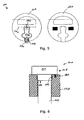
- the cover 102 comprises a locking handle 126 which is pivotabel about axis 130. Once the locking handle is pivoted such that it extends away from the cover 102, rotation about the pin 132 causes the cover to be locked or unlocked depending on whether the locking handle 126 is rotated clockwise or counter clockwise. When the locking handle 126 is in the position discloses in Fig. 5 , the cover 102 is in its locked position.
- a pad-lock locking member 134 extends through a passage 136 in the locking handle 126.
- a pad-lock may be fastened to the pad-lock locking member 134, whereby the locking handle 126 is prevented from pivoting about axis 130.
- the detector 120 is shaped so as to correspond to the shape of the cover 102.
- the detector comprises a proximity sensor (not shown) which is adapted to determine when the locking handle 126 is pivoted away from a predetermined position e.g. the position disclosed in Fig. 5 .
- a magnet sensor (not shown) may be provided which is adapted to determine when the locking handle 126 is moved away from a predetermined position. In the latter embodiment, a magnet may be incorporated into the locking handle 126 if the locking handle 126 is not made from a magnetic material.
- the detector 120 is provided in the form of a collar 138 comprising a detector registration unit 140 which is arranged to determine when the cover 102 is removed from the inlet/outlet 104.
- the collar 138 may be fastened to the inlet/outlet 104 and may comprise a threaded inner surface, which is adapted to engage the corresponding thread 112 of the insertion part 110.
- the collar 138 is fastened to the inlet/outlet 104 by being screwed onto the existing thread.
- a screw (not shown) may be arranged such that it may be screwed into the outer surface of the inlet/outlet 104, whereby the collar 138 is fastened to the inlet/outlet 104.
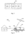
- Fig. 7 discloses an example of the electrical components of detector 120.
- the detector 120 comprises a detector registration unit 140 which is electrically connected to a processing unit 142.
- the detector registration unit 140 is arranged such that if the detector is removed from the cover 102 and/or if the cover 102 is removed from the inlet/outlet 104, then this will be registered by the detector registration unit 140.
- the processing unit 142 will operate a transceiver unit 144 which is adapted to emit a signal e.g. a radio signal, to one or more external units 146.
- the transceiver unit 146 may alternatively be provided in the form of a separate transmitter unit and a separate receiver unit.
- Fig. 8 discloses an alarm system 148 comprising a tank closing unit 100 and a first external receiver unit 146.
- the tank closing unit 100 is used to close the fuel tank of a vehicle 150.
- the first external receiver unit 146 is provided at a hidden place e.g. inside the drivers cabin 152 of the vehicle.
- the tank closing unit 100 emits a signal 154 (e.g. a radio signal) to the first external receiver unit 146.
- the external receiver unit 146 is adapted to emit a sound adapted to cause the thieves to run away.
- the first external receiver unit 146 emits a signal 156 to a second external receiver unit (not shown) which may be located near by e.g. in a house.
- the first receiver unit 146 sends a signal to a mobile device (not shown) via a satellite 158.
- the mobile device may be a mobile telephone.
- the tank closing unit 100 may be adapted to communicate directly with the second external receiver unit i.e. not via the first external receiver unit.
Landscapes
- Engineering & Computer Science (AREA)
- Life Sciences & Earth Sciences (AREA)
- Sustainable Development (AREA)
- Sustainable Energy (AREA)
- Chemical & Material Sciences (AREA)
- Combustion & Propulsion (AREA)
- Transportation (AREA)
- Mechanical Engineering (AREA)
- Closures For Containers (AREA)
- Accessory Devices And Overall Control Thereof (AREA)
- Cooling, Air Intake And Gas Exhaust, And Fuel Tank Arrangements In Propulsion Units (AREA)
Priority Applications (1)
| Application Number | Priority Date | Filing Date | Title |
|---|---|---|---|
| PL11729360T PL2576263T3 (pl) | 2010-05-28 | 2011-05-27 | Element zamykający zbiornik |
Applications Claiming Priority (2)
| Application Number | Priority Date | Filing Date | Title |
|---|---|---|---|
| DKPA201000470 | 2010-05-28 | ||
| PCT/DK2011/000052 WO2011147415A1 (en) | 2010-05-28 | 2011-05-27 | A tank closing unit |
Publications (2)
| Publication Number | Publication Date |
|---|---|
| EP2576263A1 EP2576263A1 (en) | 2013-04-10 |
| EP2576263B1 true EP2576263B1 (en) | 2014-10-29 |
Family
ID=44583891
Family Applications (1)
| Application Number | Title | Priority Date | Filing Date |
|---|---|---|---|
| EP11729360.5A Active EP2576263B1 (en) | 2010-05-28 | 2011-05-27 | A tank closing unit |
Country Status (5)
| Country | Link |
|---|---|
| EP (1) | EP2576263B1 (da) |
| DK (1) | DK2576263T3 (da) |
| ES (1) | ES2529245T3 (da) |
| PL (1) | PL2576263T3 (da) |
| WO (1) | WO2011147415A1 (da) |
Families Citing this family (2)
| Publication number | Priority date | Publication date | Assignee | Title |
|---|---|---|---|---|
| GB2505866A (en) * | 2012-07-06 | 2014-03-19 | David John Stuart | Alarm apparatus including vehicle fuel cap and sensor |
| WO2014167589A1 (en) * | 2013-04-11 | 2014-10-16 | Dario Bartesaghi | Security device for tanks, and associated assembly |
Family Cites Families (7)
| Publication number | Priority date | Publication date | Assignee | Title |
|---|---|---|---|---|
| DE19807452B4 (de) * | 1998-02-21 | 2005-03-24 | Trebe-Elektronik Gmbh & Co Kg | Vorrichtung zur Verhinderung unbefugter Entnahme von Treibstoff aus Treibstofftanks |
| GB2343283A (en) | 1998-10-28 | 2000-05-03 | Robert William Wilkinson | A fuel tank alarm system |
| US6271753B1 (en) | 2000-03-21 | 2001-08-07 | Kavita M Shukla | Smart lid |
| US20070137730A1 (en) * | 2005-12-15 | 2007-06-21 | Stant Manufacturing Inc. | Filler neck closure detector |
| FR2897683B3 (fr) * | 2006-02-17 | 2008-04-18 | Tanguy Herbert | Systeme electronique de detection/alarme sans fil,permettant la surveillance du niveau d'un liquide contenu dans un reservoir ou une citerne |
| ITTO20070113A1 (it) * | 2007-02-15 | 2008-08-16 | Eltek Spa | Dispositivo di rilevazione per veicoli |
| HU3516U (en) * | 2008-07-31 | 2008-11-28 | Zoltan Kuthi | Anti-theft protection of draining for fuel tanks |
-
2011
- 2011-05-27 PL PL11729360T patent/PL2576263T3/pl unknown
- 2011-05-27 ES ES11729360.5T patent/ES2529245T3/es active Active
- 2011-05-27 DK DK11729360.5T patent/DK2576263T3/da active
- 2011-05-27 EP EP11729360.5A patent/EP2576263B1/en active Active
- 2011-05-27 WO PCT/DK2011/000052 patent/WO2011147415A1/en not_active Ceased
Also Published As
| Publication number | Publication date |
|---|---|
| EP2576263A1 (en) | 2013-04-10 |
| ES2529245T3 (es) | 2015-02-18 |
| DK2576263T3 (da) | 2015-01-26 |
| PL2576263T3 (pl) | 2015-05-29 |
| WO2011147415A1 (en) | 2011-12-01 |
Similar Documents
| Publication | Publication Date | Title |
|---|---|---|
| US7688201B2 (en) | Detection device for vehicles | |
| US10940984B2 (en) | Battery powered keyless locking cap | |
| EP3189198B1 (en) | Bicycle security device | |
| US9715802B2 (en) | Alarmed theft-preventing device | |
| WO1999022277A1 (en) | Locking device for tools and equipment | |
| WO2005094172A2 (en) | Monitorable locking assemblies | |
| ZA200502849B (en) | Bicycle lock | |
| Prashantkumar et al. | Two wheeler vehicle security system | |
| EP2576263B1 (en) | A tank closing unit | |
| US20170086610A1 (en) | Deterrent and alert system for a beverage container | |
| CN106800009A (zh) | 一种车载防盗报警系统 | |
| KR101169754B1 (ko) | 자전거용 위치추적장치 | |
| CN205534534U (zh) | 防盗阀 | |
| CN209351239U (zh) | 一种具有防盗功能的汽车钢质燃油箱 | |
| KR101061836B1 (ko) | 유체 도난 감시시스템 | |
| TW201738448A (zh) | 用於二輪車的上鎖裝置 | |
| KR20160131174A (ko) | 오토바이 도난 방지 장치 | |
| KR100997311B1 (ko) | 유체 도난 감시시스템 | |
| KR101656713B1 (ko) | 자전거 도난방지장치 | |
| WO2001011896A3 (en) | Dtmf interface for vehicle control and security system | |
| KR101540279B1 (ko) | 오토바이 도난 방지 장치 | |
| US20250375988A1 (en) | Tire valve with a secondary air release mechanism | |
| CN103507753B (zh) | 一种汽车防盗装置和汽车 | |
| CN109263463A (zh) | 一种油箱防盗报警器 | |
| CN212889850U (zh) | 一种油箱防盗系统 |
Legal Events
| Date | Code | Title | Description |
|---|---|---|---|
| PUAI | Public reference made under article 153(3) epc to a published international application that has entered the european phase |
Free format text: ORIGINAL CODE: 0009012 |
|
| 17P | Request for examination filed |
Effective date: 20121220 |
|
| AK | Designated contracting states |
Kind code of ref document: A1 Designated state(s): AL AT BE BG CH CY CZ DE DK EE ES FI FR GB GR HR HU IE IS IT LI LT LU LV MC MK MT NL NO PL PT RO RS SE SI SK SM TR |
|
| RAP1 | Party data changed (applicant data changed or rights of an application transferred) |
Owner name: KULDBJERG INVEST APS |
|
| RIN1 | Information on inventor provided before grant (corrected) |
Inventor name: VINGE, CARL |
|
| RAP1 | Party data changed (applicant data changed or rights of an application transferred) |
Owner name: VINGE, CARL |
|
| RIN1 | Information on inventor provided before grant (corrected) |
Inventor name: VINGE, CARL |
|
| DAX | Request for extension of the european patent (deleted) | ||
| 17Q | First examination report despatched |
Effective date: 20131015 |
|
| GRAP | Despatch of communication of intention to grant a patent |
Free format text: ORIGINAL CODE: EPIDOSNIGR1 |
|
| INTG | Intention to grant announced |
Effective date: 20140312 |
|
| GRAS | Grant fee paid |
Free format text: ORIGINAL CODE: EPIDOSNIGR3 |
|
| GRAA | (expected) grant |
Free format text: ORIGINAL CODE: 0009210 |
|
| AK | Designated contracting states |
Kind code of ref document: B1 Designated state(s): AL AT BE BG CH CY CZ DE DK EE ES FI FR GB GR HR HU IE IS IT LI LT LU LV MC MK MT NL NO PL PT RO RS SE SI SK SM TR |
|
| REG | Reference to a national code |
Ref country code: GB Ref legal event code: FG4D |
|
| REG | Reference to a national code |
Ref country code: CH Ref legal event code: EP |
|
| REG | Reference to a national code |
Ref country code: AT Ref legal event code: REF Ref document number: 693388 Country of ref document: AT Kind code of ref document: T Effective date: 20141115 |
|
| REG | Reference to a national code |
Ref country code: IE Ref legal event code: FG4D |
|
| REG | Reference to a national code |
Ref country code: DE Ref legal event code: R096 Ref document number: 602011010952 Country of ref document: DE Effective date: 20141211 |
|
| REG | Reference to a national code |
Ref country code: DK Ref legal event code: T3 Effective date: 20150123 |
|
| REG | Reference to a national code |
Ref country code: SE Ref legal event code: TRGR |
|
| REG | Reference to a national code |
Ref country code: NL Ref legal event code: T3 |
|
| REG | Reference to a national code |
Ref country code: ES Ref legal event code: FG2A Ref document number: 2529245 Country of ref document: ES Kind code of ref document: T3 Effective date: 20150218 |
|
| REG | Reference to a national code |
Ref country code: AT Ref legal event code: MK05 Ref document number: 693388 Country of ref document: AT Kind code of ref document: T Effective date: 20141029 |
|
| REG | Reference to a national code |
Ref country code: LT Ref legal event code: MG4D |
|
| PG25 | Lapsed in a contracting state [announced via postgrant information from national office to epo] |
Ref country code: FI Free format text: LAPSE BECAUSE OF FAILURE TO SUBMIT A TRANSLATION OF THE DESCRIPTION OR TO PAY THE FEE WITHIN THE PRESCRIBED TIME-LIMIT Effective date: 20141029 Ref country code: NO Free format text: LAPSE BECAUSE OF FAILURE TO SUBMIT A TRANSLATION OF THE DESCRIPTION OR TO PAY THE FEE WITHIN THE PRESCRIBED TIME-LIMIT Effective date: 20150129 Ref country code: PT Free format text: LAPSE BECAUSE OF FAILURE TO SUBMIT A TRANSLATION OF THE DESCRIPTION OR TO PAY THE FEE WITHIN THE PRESCRIBED TIME-LIMIT Effective date: 20150302 Ref country code: LT Free format text: LAPSE BECAUSE OF FAILURE TO SUBMIT A TRANSLATION OF THE DESCRIPTION OR TO PAY THE FEE WITHIN THE PRESCRIBED TIME-LIMIT Effective date: 20141029 Ref country code: IS Free format text: LAPSE BECAUSE OF FAILURE TO SUBMIT A TRANSLATION OF THE DESCRIPTION OR TO PAY THE FEE WITHIN THE PRESCRIBED TIME-LIMIT Effective date: 20150228 |
|
| PGFP | Annual fee paid to national office [announced via postgrant information from national office to epo] |
Ref country code: ES Payment date: 20150313 Year of fee payment: 5 Ref country code: NL Payment date: 20150312 Year of fee payment: 5 |
|
| PG25 | Lapsed in a contracting state [announced via postgrant information from national office to epo] |
Ref country code: GR Free format text: LAPSE BECAUSE OF FAILURE TO SUBMIT A TRANSLATION OF THE DESCRIPTION OR TO PAY THE FEE WITHIN THE PRESCRIBED TIME-LIMIT Effective date: 20150130 Ref country code: HR Free format text: LAPSE BECAUSE OF FAILURE TO SUBMIT A TRANSLATION OF THE DESCRIPTION OR TO PAY THE FEE WITHIN THE PRESCRIBED TIME-LIMIT Effective date: 20141029 Ref country code: RS Free format text: LAPSE BECAUSE OF FAILURE TO SUBMIT A TRANSLATION OF THE DESCRIPTION OR TO PAY THE FEE WITHIN THE PRESCRIBED TIME-LIMIT Effective date: 20141029 Ref country code: LV Free format text: LAPSE BECAUSE OF FAILURE TO SUBMIT A TRANSLATION OF THE DESCRIPTION OR TO PAY THE FEE WITHIN THE PRESCRIBED TIME-LIMIT Effective date: 20141029 Ref country code: AT Free format text: LAPSE BECAUSE OF FAILURE TO SUBMIT A TRANSLATION OF THE DESCRIPTION OR TO PAY THE FEE WITHIN THE PRESCRIBED TIME-LIMIT Effective date: 20141029 Ref country code: CY Free format text: LAPSE BECAUSE OF FAILURE TO SUBMIT A TRANSLATION OF THE DESCRIPTION OR TO PAY THE FEE WITHIN THE PRESCRIBED TIME-LIMIT Effective date: 20141029 |
|
| REG | Reference to a national code |
Ref country code: PL Ref legal event code: T3 |
|
| REG | Reference to a national code |
Ref country code: DE Ref legal event code: R097 Ref document number: 602011010952 Country of ref document: DE |
|
| PG25 | Lapsed in a contracting state [announced via postgrant information from national office to epo] |
Ref country code: CZ Free format text: LAPSE BECAUSE OF FAILURE TO SUBMIT A TRANSLATION OF THE DESCRIPTION OR TO PAY THE FEE WITHIN THE PRESCRIBED TIME-LIMIT Effective date: 20141029 Ref country code: EE Free format text: LAPSE BECAUSE OF FAILURE TO SUBMIT A TRANSLATION OF THE DESCRIPTION OR TO PAY THE FEE WITHIN THE PRESCRIBED TIME-LIMIT Effective date: 20141029 Ref country code: SK Free format text: LAPSE BECAUSE OF FAILURE TO SUBMIT A TRANSLATION OF THE DESCRIPTION OR TO PAY THE FEE WITHIN THE PRESCRIBED TIME-LIMIT Effective date: 20141029 Ref country code: RO Free format text: LAPSE BECAUSE OF FAILURE TO SUBMIT A TRANSLATION OF THE DESCRIPTION OR TO PAY THE FEE WITHIN THE PRESCRIBED TIME-LIMIT Effective date: 20141029 |
|
| PGFP | Annual fee paid to national office [announced via postgrant information from national office to epo] |
Ref country code: IT Payment date: 20150508 Year of fee payment: 5 |
|
| PLBE | No opposition filed within time limit |
Free format text: ORIGINAL CODE: 0009261 |
|
| STAA | Information on the status of an ep patent application or granted ep patent |
Free format text: STATUS: NO OPPOSITION FILED WITHIN TIME LIMIT |
|
| 26N | No opposition filed |
Effective date: 20150730 |
|
| REG | Reference to a national code |
Ref country code: CH Ref legal event code: PL |
|
| PG25 | Lapsed in a contracting state [announced via postgrant information from national office to epo] |
Ref country code: MC Free format text: LAPSE BECAUSE OF FAILURE TO SUBMIT A TRANSLATION OF THE DESCRIPTION OR TO PAY THE FEE WITHIN THE PRESCRIBED TIME-LIMIT Effective date: 20141029 Ref country code: LU Free format text: LAPSE BECAUSE OF FAILURE TO SUBMIT A TRANSLATION OF THE DESCRIPTION OR TO PAY THE FEE WITHIN THE PRESCRIBED TIME-LIMIT Effective date: 20150527 Ref country code: CH Free format text: LAPSE BECAUSE OF NON-PAYMENT OF DUE FEES Effective date: 20150531 Ref country code: LI Free format text: LAPSE BECAUSE OF NON-PAYMENT OF DUE FEES Effective date: 20150531 |
|
| REG | Reference to a national code |
Ref country code: IE Ref legal event code: MM4A |
|
| PG25 | Lapsed in a contracting state [announced via postgrant information from national office to epo] |
Ref country code: SI Free format text: LAPSE BECAUSE OF FAILURE TO SUBMIT A TRANSLATION OF THE DESCRIPTION OR TO PAY THE FEE WITHIN THE PRESCRIBED TIME-LIMIT Effective date: 20141029 |
|
| PG25 | Lapsed in a contracting state [announced via postgrant information from national office to epo] |
Ref country code: IE Free format text: LAPSE BECAUSE OF NON-PAYMENT OF DUE FEES Effective date: 20150527 |
|
| REG | Reference to a national code |
Ref country code: FR Ref legal event code: PLFP Year of fee payment: 6 |
|
| PG25 | Lapsed in a contracting state [announced via postgrant information from national office to epo] |
Ref country code: MT Free format text: LAPSE BECAUSE OF FAILURE TO SUBMIT A TRANSLATION OF THE DESCRIPTION OR TO PAY THE FEE WITHIN THE PRESCRIBED TIME-LIMIT Effective date: 20141029 |
|
| REG | Reference to a national code |
Ref country code: NL Ref legal event code: MM Effective date: 20160601 |
|
| PG25 | Lapsed in a contracting state [announced via postgrant information from national office to epo] |
Ref country code: IT Free format text: LAPSE BECAUSE OF NON-PAYMENT OF DUE FEES Effective date: 20160527 Ref country code: NL Free format text: LAPSE BECAUSE OF NON-PAYMENT OF DUE FEES Effective date: 20160601 |
|
| REG | Reference to a national code |
Ref country code: FR Ref legal event code: PLFP Year of fee payment: 7 |
|
| PG25 | Lapsed in a contracting state [announced via postgrant information from national office to epo] |
Ref country code: BG Free format text: LAPSE BECAUSE OF FAILURE TO SUBMIT A TRANSLATION OF THE DESCRIPTION OR TO PAY THE FEE WITHIN THE PRESCRIBED TIME-LIMIT Effective date: 20141029 Ref country code: SM Free format text: LAPSE BECAUSE OF FAILURE TO SUBMIT A TRANSLATION OF THE DESCRIPTION OR TO PAY THE FEE WITHIN THE PRESCRIBED TIME-LIMIT Effective date: 20141029 Ref country code: HU Free format text: LAPSE BECAUSE OF FAILURE TO SUBMIT A TRANSLATION OF THE DESCRIPTION OR TO PAY THE FEE WITHIN THE PRESCRIBED TIME-LIMIT; INVALID AB INITIO Effective date: 20110527 |
|
| PG25 | Lapsed in a contracting state [announced via postgrant information from national office to epo] |
Ref country code: TR Free format text: LAPSE BECAUSE OF FAILURE TO SUBMIT A TRANSLATION OF THE DESCRIPTION OR TO PAY THE FEE WITHIN THE PRESCRIBED TIME-LIMIT Effective date: 20141029 |
|
| PG25 | Lapsed in a contracting state [announced via postgrant information from national office to epo] |
Ref country code: BE Free format text: LAPSE BECAUSE OF FAILURE TO SUBMIT A TRANSLATION OF THE DESCRIPTION OR TO PAY THE FEE WITHIN THE PRESCRIBED TIME-LIMIT Effective date: 20141029 |
|
| REG | Reference to a national code |
Ref country code: FR Ref legal event code: PLFP Year of fee payment: 8 |
|
| PG25 | Lapsed in a contracting state [announced via postgrant information from national office to epo] |
Ref country code: ES Free format text: LAPSE BECAUSE OF NON-PAYMENT OF DUE FEES Effective date: 20160528 |
|
| REG | Reference to a national code |
Ref country code: ES Ref legal event code: FD2A Effective date: 20180627 |
|
| PG25 | Lapsed in a contracting state [announced via postgrant information from national office to epo] |
Ref country code: MK Free format text: LAPSE BECAUSE OF FAILURE TO SUBMIT A TRANSLATION OF THE DESCRIPTION OR TO PAY THE FEE WITHIN THE PRESCRIBED TIME-LIMIT Effective date: 20141029 |
|
| PG25 | Lapsed in a contracting state [announced via postgrant information from national office to epo] |
Ref country code: AL Free format text: LAPSE BECAUSE OF FAILURE TO SUBMIT A TRANSLATION OF THE DESCRIPTION OR TO PAY THE FEE WITHIN THE PRESCRIBED TIME-LIMIT Effective date: 20141029 |
|
| PGFP | Annual fee paid to national office [announced via postgrant information from national office to epo] |
Ref country code: GB Payment date: 20240527 Year of fee payment: 14 |
|
| PGFP | Annual fee paid to national office [announced via postgrant information from national office to epo] |
Ref country code: FR Payment date: 20240527 Year of fee payment: 14 |
|
| PGFP | Annual fee paid to national office [announced via postgrant information from national office to epo] |
Ref country code: PL Payment date: 20240509 Year of fee payment: 14 |
|
| PGFP | Annual fee paid to national office [announced via postgrant information from national office to epo] |
Ref country code: DE Payment date: 20250529 Year of fee payment: 15 |
|
| PGFP | Annual fee paid to national office [announced via postgrant information from national office to epo] |
Ref country code: DK Payment date: 20250526 Year of fee payment: 15 |
|
| PGFP | Annual fee paid to national office [announced via postgrant information from national office to epo] |
Ref country code: SE Payment date: 20250527 Year of fee payment: 15 |
|
| GBPC | Gb: european patent ceased through non-payment of renewal fee |
Effective date: 20250527 |