EP2575554B1 - Element für ein beleuchtetes regal, beleuchtetes regal und beleuchtete ragaleinheit - Google Patents
Element für ein beleuchtetes regal, beleuchtetes regal und beleuchtete ragaleinheit Download PDFInfo
- Publication number
- EP2575554B1 EP2575554B1 EP11720312.5A EP11720312A EP2575554B1 EP 2575554 B1 EP2575554 B1 EP 2575554B1 EP 11720312 A EP11720312 A EP 11720312A EP 2575554 B1 EP2575554 B1 EP 2575554B1
- Authority
- EP
- European Patent Office
- Prior art keywords
- shelf
- lighted
- light
- front edge
- blocking mask
- Prior art date
- Legal status (The legal status is an assumption and is not a legal conclusion. Google has not performed a legal analysis and makes no representation as to the accuracy of the status listed.)
- Not-in-force
Links
- 238000009792 diffusion process Methods 0.000 claims description 37
- 230000000903 blocking effect Effects 0.000 claims 13
- 230000011664 signaling Effects 0.000 description 14
- 239000000463 material Substances 0.000 description 4
- 230000000295 complement effect Effects 0.000 description 3
- 230000000007 visual effect Effects 0.000 description 3
- 230000004069 differentiation Effects 0.000 description 2
- 239000000123 paper Substances 0.000 description 2
- 229920003023 plastic Polymers 0.000 description 2
- 238000004026 adhesive bonding Methods 0.000 description 1
- 229920002457 flexible plastic Polymers 0.000 description 1
- 238000005286 illumination Methods 0.000 description 1
- 238000009434 installation Methods 0.000 description 1
- 239000004973 liquid crystal related substance Substances 0.000 description 1
- 230000001737 promoting effect Effects 0.000 description 1
- 230000002787 reinforcement Effects 0.000 description 1
- 238000003466 welding Methods 0.000 description 1
Images


Classifications
-
- A—HUMAN NECESSITIES
- A47—FURNITURE; DOMESTIC ARTICLES OR APPLIANCES; COFFEE MILLS; SPICE MILLS; SUCTION CLEANERS IN GENERAL
- A47F—SPECIAL FURNITURE, FITTINGS, OR ACCESSORIES FOR SHOPS, STOREHOUSES, BARS, RESTAURANTS OR THE LIKE; PAYING COUNTERS
- A47F11/00—Arrangements in shop windows, shop floors or show cases
- A47F11/06—Means for bringing about special optical effects
- A47F11/10—Arrangements of light sources
-
- A—HUMAN NECESSITIES
- A47—FURNITURE; DOMESTIC ARTICLES OR APPLIANCES; COFFEE MILLS; SPICE MILLS; SUCTION CLEANERS IN GENERAL
- A47B—TABLES; DESKS; OFFICE FURNITURE; CABINETS; DRAWERS; GENERAL DETAILS OF FURNITURE
- A47B2220/00—General furniture construction, e.g. fittings
- A47B2220/0075—Lighting
- A47B2220/0077—Lighting for furniture, e.g. cupboards and racks
-
- F—MECHANICAL ENGINEERING; LIGHTING; HEATING; WEAPONS; BLASTING
- F21—LIGHTING
- F21W—INDEXING SCHEME ASSOCIATED WITH SUBCLASSES F21K, F21L, F21S and F21V, RELATING TO USES OR APPLICATIONS OF LIGHTING DEVICES OR SYSTEMS
- F21W2131/00—Use or application of lighting devices or systems not provided for in codes F21W2102/00-F21W2121/00
- F21W2131/30—Lighting for domestic or personal use
- F21W2131/301—Lighting for domestic or personal use for furniture
-
- F—MECHANICAL ENGINEERING; LIGHTING; HEATING; WEAPONS; BLASTING
- F21—LIGHTING
- F21Y—INDEXING SCHEME ASSOCIATED WITH SUBCLASSES F21K, F21L, F21S and F21V, RELATING TO THE FORM OR THE KIND OF THE LIGHT SOURCES OR OF THE COLOUR OF THE LIGHT EMITTED
- F21Y2115/00—Light-generating elements of semiconductor light sources
- F21Y2115/10—Light-emitting diodes [LED]
Definitions
- the present invention relates to a luminous tablet element, a luminous tablet comprising such an element and a luminous shelf comprising such a luminous tablet, intended to be used to form any type of storage rack and / or presentation of objects.
- Tablets are commonly used to constitute storage racks and / or presentation of objects.
- the shelves are arranged on a support or assembled to amounts to form shelves.
- the shelves thus formed can be freestanding or be attached to a wall, for example a wall.
- Such tablets can thus be used in industry, in shops or even in private homes.
- the tablets are often coupled to signaling elements, for example tabs provided on the nose of the tablet as described for example in WO 98/49490 A .
- the labels may include any type of product information such as, for example, price, product references, brands, etc. Labels may also include any type of racking information, such as aisle, row, and so on.
- the labels may be traditional labels for example printed on paper or any other equivalent medium.
- the labels can also be electronic labels, thin, provided with a display screen, for example liquid crystal. The content of the display of this screen can be controlled by a microprocessor, for example remotely controllable by means of the central computer of the store or the storage location.
- the labels are often not very visible, not very readable and do not allow to highlight sufficiently the products they present.
- store and storage managers are increasingly planning illuminating systems, for example by means of light spots directed towards the labels to illuminate them. These illuminating systems are nevertheless impractical to install and expensive.
- the location of the spotlights must be uniquely adapted for each new rack configuration which makes their installation laborious.
- light spots can be easily damaged during traffic or by acts of negligence or even vandalism.
- the present invention aims to remedy these drawbacks by proposing a luminous tablet element, a luminous tablet and a light shelf.
- a signage element such as a tag
- the element, shelf and light shelf being robust and enabling new visual effects to increase differentiation and attractiveness of the products presented.
- the invention relates to a luminous tablet element comprising at least one substantially flat upper bearing surface defined by a front edge of a tablet, fastening means provided under said bearing surface and able to receive at least one signaling element. means for securing said luminous tablet element to at least one support.
- This luminous tablet is remarkable in that said tablet element comprises at least one shutter mask delimited by a front edge of a shutter mask and defining, under said bearing surface, at least one housing having a front opening provided between said front edges of tablet and shutter mask, said housing being adapted to receive light means disposed between said fixing means and said shutter mask, in that said fixing means are arranged not to limit the front diffusion of the light emitted by said light means through said front opening, and in that said shutter mask is adapted to limit the dorsal diffusion and the downward diffusion of the light emitted by said light means.
- the luminous tablet element thus makes it possible to effectively illuminate the signaling element in order to improve its visibility and readability.
- the created visual effect is new and makes it possible to increase the differentiation and the attractiveness of the products presented.
- the shutter mask allows in particular to focus the light on the signaling element.
- the element for luminous tablet according to the invention may be a tablet to which it is appropriate to add luminous means to transform it into a luminous tablet.
- Said fastening means are preferably arranged to define a fastening plane substantially parallel to said bearing surface.
- said fastening means have a shape selected from the group comprising at least one dovetail, a C-profile, an inverted V profile, an open inverted V profile.
- Said bearing surface preferably comprises first through orifices provided between said fastening means and said shutter mask, said first through orifices being each adapted to allow the light emitted by said light means to pass through said luminous tablet element.
- Said shutter mask advantageously comprises second through holes each able to let the light emitted by said light means through said light shelf element.
- the signaling element may be a label holder adapted to receive at least one of said traditional label, electronic tag.
- the element for luminous tablet is formed of at least two separate parts joined together, a first part forming at least said bearing surface, a second part forming at least said blanking mask, the fastening means being carried by at least one of said first and second parts.
- said fixing means are carried by said bearing surface.
- said fixing means can advantageously arranged to be at least partly tangent to said front edge of the tablet.
- said fixing means are carried by said shutter mask.
- said fixing means may advantageously be arranged to be at least partly tangent to said front edge of the shutter mask.
- At least one of said front edges of a tablet, of a closure mask preferably forms at least one ample fold defining a groove forming at least in part said fixing means.
- Said shutter mask advantageously extends under said bearing surface so that said front edge of the shutter mask defines a flange provided beyond said front edge of the tablet and adapted to receive the support of said signal element.
- the invention also relates to a luminous shelf for shelving, remarkable in that it comprises at least one element for luminous shelf as described above, luminous means provided in said housing, at least one signal element secured by said fixing means said luminous tablet element, said luminous tablet element and said signal element being arranged so that said signal element at least partially closes said front opening.
- the luminous means being received in the housing, they are thus protected and their access is made difficult which reinforces the robustness of the luminous tablet comprising such a luminous tablet element.
- said signaling element is preferably arranged to close all of said front opening.
- said signaling element is arranged to close only a part of said front opening by preserving at least one unsealed line through which it allows the passage of the light emitted by said light means so as to to form a luminous ray.
- Said signaling element is advantageously arranged to allow the passage of light emitted by said light means through at least part of the surface of said signaling element.
- the invention relates to a light shelf, remarkable in that it comprises at least one light shelf as described above, said light shelf being connected to at least one support for forming said light shelf.
- the luminous tablet 1 to -1 k comprises a luminous tablet element formed of several parts secured to each other and provided with means for securing to a support (not shown) such as for example vertical uprights.
- the luminous tablet thus forms, with the uprights and other shelves luminous or not, a light shelf.
- the light shelf may also be carried by cleats fixed on a wall, for example a wall.
- the element for a light shelf comprises in particular a plate defining a substantially planar upper bearing surface 2 and fastening means 5a-5k able to receive an interchangeable signaling element 3 such as, for example, a label holder receiving a label.
- the label may be a traditional paper, cardboard, plastic material or other type of label.
- the label may also be an electronic tag.
- the signaling element 3 may finally be any other suitable element.
- the fastening means are provided under the bearing surface. In the illustrated examples, the label is not shown.
- the element for luminous tablet also comprises a shutter mask 4 to -4 k provided under the bearing surface 2 with which it defines a housing 5 provided with a front opening oriented towards the front of the luminous tablet 1 to -1 k , this frontal opening being intended for at least partly blocked by the signaling element 3.
- the luminous tablet 1 to -1 k comprises luminous means 6 (represented by a rectangle), arranged in the housing 5.
- These luminous means 6 are for example in the form of a light strip, for example a strip of LEDs, or a fluorescent tube, for example of the T5 type.
- the bearing surface 2 of the light shelf 1 a- 1 k limit the upward diffusion of the light emitted by the light means 6.
- the shutter mask 4 has -4 k limit the back diffusion (to the rear of the light shelf 1 a - k ) and downwards, light emitted by the light means 6.
- the fixing means 5 has -5 k define a substantially parallel plane of attachment to the support surface 2 do not limit the forward scatter of light emitted by the light means 6.
- the front opening is maximum and thus enables optimal frontal diffusion of the light.
- the support surface 2 may comprise a plurality of first through holes 21 provided for example between the fastening means 5 c -5 and 5 f k and the light means 6. These first through orifices 21 allow upward diffusion of the light emitted by the light means 6.
- the shutter mask 4 c -4 g and 4 k may comprise a plurality of second through holes 41 and / or third through holes 42 These second through orifices 41 and / or third through orifices 42 allow downward and / or rearward diffusion of the light emitted by the light means 6.
- the signaling element is a label holder 3 having a label (no shown).
- the label holder 3 is made of flexible and transparent plastic material.
- Each label holder 3 comprises an elongated blade 30 whose lower part is extended by a return 31 folded forward on the blade 30 in order to define, with the blade 30, a slot into which a traditional label can be inserted.
- the upper part of the blade 30 is extended forward and backward by fastening lobes 32 of the label holder 3 intended to cooperate with the fixing means 5 a -5 k of the light shelf 1 a -1 k to ensure the fixing of the label holder 3 on the light shelf 1 to -1 k .
- the label holder 3 can of course be of any other shape and made of any other material compatible with its use and the fixing means 5a-5k of the light tablet 1a-1k.
- the label holder 3 and the label that it contains are translucent so that the light is perceptible through the label holder 3 and the label by an observer arranged in front of the luminous tablet 1 a -1 k .
- the plate of the light shelf 1 has a shelf comprises front end provided with an ample bend 20 defining the front edge of light and tablet 1 has a first groove. Furthermore, the plate has cutouts 22, aligned, substantially parallel to the front edge of the tablet, only one is shown. These cutouts 22 are deformed towards the underside of the light shelf in order to define second grooves.
- the first groove and the second grooves define a dovetail in which the fixing lobes 32 of the label holder 3 are housed to ensure the fixing of the label holder 3 on the light shelf 1a.
- the fixing means 5 a are partly tangential to the shelf front edge.
- the shutter mask 4 has a shaped part having a Z first flange 43 fixed under the bearing surface 2 of the light shelf 1 has a back 44 substantially perpendicular to the first wing 43 and extended by a second flange 45 substantially perpendicular to the back 44 and therefore substantially parallel to the bearing surface 2.
- the front end of the second wing 45 is provided with a tight envelope 40 making the cutting edge of the shutter mask 4 has all unreachable preserving maximum frontal opening.
- This tight fold 40 delimits a front edge of the shutter mask beyond the front edge of the tablet delimited by the wide fold 20.
- the tight fold 40 forms a support flange adapted to receive the support of the blade 30 of the label holder 3.
- the orientation of the label holder 3 is thus determined in advance in an optimized manner to ensure the readability of the information carried by the label.
- the lighting means 6 are arranged in the rear upper corner of the housing 5 defined by the mask 4 has shutter and the tray under the support surface 2.
- the mask 4 has shutter comprises a plurality of second through holes 41, aligned substantially parallel at the front edge of the shutter mask and only one of which is shown. These second through orifices 41 allow the downward diffusion of the light emitted by the light means 6 and symbolized by the arrow L2.
- the label holder 3 and the label also allow the frontal diffusion of the light emitted by the luminous means 6 and symbolized by the arrow L4 through the label holder 3.
- the luminous tablet 1a of this first embodiment thus allows the frontal diffusion L4 and L2 downward of the light emitted by the light means 6.
- the front L4 light diffusion is achieved by the front opening delimited by the front edges of tray and shutter mask through the label holder 3.
- the tray of the light shelf 1b has a front end of the tablet provided with a wide fold 20 defining the front edge of the light shelf 1b and a first groove.
- the shutter mask 4b is substantially similar to shutter mask 4a of the previous embodiment and the fixing means 5 b are partially tangent to the shelf front edge.
- Light shelf 1 b comprises an intermediate part 7 in the form of part-Z, the first wing 70 is disposed between the first wing 43 of the shutter mask 4b and the supporting surface 2.
- the back 70 and the second flange 72 of the intermediate piece 7 define a second groove forming, with the first groove, a dovetail.
- the fastening means 5b are tangent to the front edge of the tablet.
- the label holder 3 and the light means 6 are substantially similar to those of the previous embodiment.
- the luminous tablet 1b of this second embodiment thus allows the L4 and L2 downward diffusion L2 of the light emitted by the light means 6.
- the front L4 light diffusion is achieved by the front opening delimited by the front edges tray and shutter mask.
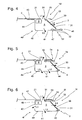
- the plateau of the third embodiment is substantially similar to that of the figure 1 . It differs in that it includes a plurality of first through holes 21, aligned, provided between the fastening means 5 c and the lighting means 6 and substantially parallel to the shelf front edge. These first through orifices 21 allow the diffusion, towards the top, of the light emitted by the luminous means 6 and symbolized by the arrow L1.
- the shutter mask 4 c is substantially similar to those of Figures 1 and 2 . It differs in that it comprises a plurality of third through holes 42 provided through the return 44 and allowing the dorsal diffusion of the light emitted by the light means 6 and symbolized by the arrow L3.
- the label holder 3 and the light means 6 are substantially similar to those of the previous embodiment.
- the luminous tablet 1 c of this third embodiment thus allows the frontal diffusion L4, down L2, dorsal L3 and L1 top of the light emitted by the light means 6.
- the edge 4 c shutter face is not positioned beyond the front edge of the tablet and the label holder 3 has a height less than the distance separating the plate of the second flange 45 of the shutter mask 4 c .
- a luminous line is formed between the bottom of the label holder 3 and the shutter mask 4 c .
- the luminous tablet 1 c of this third embodiment also allows the front diffusion L4, down L2, dorsal L3 and up L1 of the light emitted by the light means 6.
- the intensity of the light ray is in particular superior to that of the light resulting from the frontal diffusion. This creates a new visual effect.
- the frontal diffusion L4 of light is thus realized by the front opening delimited by the frontal edges of plateau and mask shutter, a part being through the label holder 3, the other part being done by the light line.
- the tray of the light shelf 1d has a front end of the tablet provided with a tight fold 23 making the cutting edge of the light shelf 1d inaccessible.
- This tight fold 23 delimits the front edge of the tablet.
- the plate also has first through orifices 21 allowing the diffusion of the light emitted by the light means 6 and symbolized by the arrow L1.
- the plate further comprises cutouts 24 aligned provided between the first through holes 21 and the tight fold 23. These cuts 24 are deformed towards the underside of the light shelf 1 d to define stops 25 able to receive the support of the door label 3.
- the label holder 3 is substantially similar to the previous ones. As detailed below, the label holder 3 is nevertheless fixed to the shutter mask 4 d and not to the plate.
- the shutter mask 4 d has a partial Z shape including a first wing 43 fixed under the bearing surface 2 of the light shelf 1d, a return 44 substantially perpendicular to the first flange 43 and extended by a second flange 45 substantially perpendicular to the return 44 and therefore substantially parallel to the bearing surface 2.
- the front end of the second flange 45 is provided with a large ply 46 defining the front edge of the shutter mask and a first groove.
- the shutter mask 4 d further includes cutouts 47, aligned, substantially parallel to the front edge of the shutter mask and only one is shown.
- These cuts 47 are deformed towards the top of the shutter mask 4d in order to define second grooves.
- the first groove and the second grooves define a dovetail in which the fixing lobes 32 of the label holder 3 are housed to ensure the fixing of the label holder 3 on the shutter mask 4 d .
- the fixing means 5 d are partly tangent to the front edge of the shutter mask.
- the light means 6 are substantially similar to the previous ones and the label holder 3 and the label allow the frontal diffusion of the light emitted by the luminous means 6 and symbolized by the arrow L4.
- the front diffusion L4 of light is produced by the front opening delimited by the front edges of the plate and shutter mask through the label holder 3.
- the luminous tablet 1 d of this fourth embodiment thus allows the front diffusion L4, to the bottom L2 and towards the top L1 of the light emitted by the luminous means 6.
- the plate does not comprise cutouts forming abutment, the label holder bearing directly on the front edge of the tablet.
- the plate of the light shelf 1 e is provided at its front end with a complementary piece 8 disposed under the bearing surface 2, prominently relative to the plate.
- This complementary piece 8 has a C-shaped dovetail shape with two grooves and is adapted to receive the attachment lobes 32 of the label holder 3.
- the plate has first through holes 21 substantially similar to the previous ones and allowing the diffusion towards the top of the light emitted by the light means 6 and symbolized by the arrow L1.
- the shutter mask 4 e is substantially similar to that of Figures 1 and 2 .
- the light means 6 are substantially similar to the previous ones.
- the luminous tablet 1e of this fifth embodiment thus allows the frontal diffusion L4, downwards L2 and towards the top L1 of the light emitted by the light means 6.
- the front diffusion L4 of light is produced by the delimited front opening by the front edges of the plate and the shutter mask through the label holder 3.
- the plate of the light 1f tablet is substantially similar to the above and includes first through holes 21.
- the shutter mask 4 f to a lying U-shape whose upper branch 47 is secured under the bearing surface 2 of the light tablet 1f and the lower branch 49 extends substantially parallel to the bearing surface 2.
- the shutter mask 4 f is disposed under the bearing surface 2 in a prominent manner with respect to the plate. Thus the cutting edge of the tray is rendered harmless.
- the shutter mask 4f is provided with fourth threaded holes 51 provided opposite the first through orifices 21 so that the first and fourth orifices 21, 51 through allow the diffusion to the top of the light emitted by the light means 6 and symbolized by the arrow L1.
- the front end of the upper branch 47 of the shutter mask 4 f is provided with a wide fold 52 defining the front edge of the light shelf 1 f and a first groove.
- the front end of the lower branch 49 is provided with a fold tight 40 making the lower cutting edge of the shutter mask 4 f inaccessible while maintaining a maximum frontal opening.
- This tight fold 40 is provided beyond the ample fold 52 so that the tight fold 40 forms a support flange adapted to receive the support of the blade 30 of the label holder 3.
- the light means 6 are substantially similar to the previous ones .
- the shutter mask 4 f has cutouts 53 aligned, substantially parallel to the first groove, only one is shown. These cutouts 53 are deformed towards the underside of the shutter mask 4 f in order to define second grooves.
- the first groove and the second grooves define a dovetail in which the lobes for fixing the label holder 3 are housed.
- the fixing means 5 f are partly tangent to the front edge of the tablet.
- the light means 6 are substantially similar to the previous ones.
- the return valve 48 between the first and second branch 47, 49 of the shutter mask 4 f comprises third openings 42 substantially similar to those of the figure 3 and allowing the dorsal diffusion of the light emitted by the light means 6 and symbolized by the arrow L3.
- the luminous tablet 1 f of this sixth embodiment thus allows the frontal diffusion L4, downwards L2, dorsal L3 and towards the top L1 of the light emitted by the light means 6.
- the front diffusion L4 of light is produced by the front opening defined by the front edges of plate and shutter mask through the label holder 3.
- Fixing between the parts constituting the luminous tablet 1 a - f is by example provided by spot welding, gluing, riveting or any other suitable means.
- the luminous tablet 1 h - j may comprise fixing means 5 h - j such that respectively a profile C 53 ( figure 8A ), an open inverted V profile 54 ( Figure 8B ), an inverted inverted V profile 55 ( Figure 8C ).
- the shape of the signaling element 3, and in particular of its attachment zone, will of course be chosen to be compatible with these fixing means 5 h - j .
- the front edges of the plate and the shutter mask 4 h -4 j form a tight fold.
- the plateau of the luminous tablet 1 k is substantially similar to that of the figure 4 . It differs in that it comprises first orifices 21 substantially similar to those of figures 1 , 3 to 6 .
- the shutter mask 4 k is substantially similar to that of Figures 1 and 2 . It differs in that its first flange 43 'is extended at the rear by a flap 43' substantially perpendicular to the first flange 43 and to stiffen and consolidate the light shelf 1 k .
- the light shelf 1 k further comprises an intermediate piece 7 substantially similar to that of the figure 2 .
- the first flange 70 is extended at the rear by a complementary flap 70 'substantially perpendicular to the first flange 70 and to stiffen and consolidate the light shelf 1 k .
- the light means 6 and the label holder are substantially similar to those described above.
- the luminous tablet 1 k of this preferred embodiment thus allows the frontal diffusion L4 and downward L2 of the light emitted by the light means 6.
- the front diffusion L4 of light is formed by the front opening delimited by the edges front plate and shutter mask through the label holder.
- the luminous tablet 1 k is also provided with longitudinal reinforcements 10 to stiffen the support surface 2 and securing means of the luminous tablet 1 k for example to vertical uprights (not shown) or any other suitable support.
- the securing means comprise lateral flaps 11 making it possible to stiffen the luminous shelf 1 k and to bear on abutments integral with vertical uprights, orifices 12 and a rear longitudinal flap 13.
- the through holes may have any type of shape, circular, ovoid, square, rectangular or other and for example form characters or numbers.
- the labels and / or label holders may be colored and / or include cutouts promoting the frontal diffusion of light.
- the luminous means used can emit a light white or a light of any other suitable color.
- the vertical and horizontal portions of the shutter mask can be inclined.
- the second wing of the shutter mask may be non-parallel to the bearing surface to allow a housing of dimensions greater than that of the front opening, or vice versa.
Landscapes
- Display Racks (AREA)
- Arrangement Of Elements, Cooling, Sealing, Or The Like Of Lighting Devices (AREA)
- Illuminated Signs And Luminous Advertising (AREA)
Claims (18)
- Leuchtregalbodenelement (1 a-1 k) mit wenigstens einer oberen Auflagefläche (2), die im Wesentlichen eben und von einer stirnseitigen Regalbodenkante begrenzt ist, Befestigungsmitteln (5a-5k), die unter der Auflagefläche (2) vorgesehen sind und wenigstens ein Kennzeichnungselement (3) aufzunehmen vermögen, Mitteln (11-13) zum festen Verbinden des Leuchtregalbodenelements mit wenigstens einem Träger, dadurch gekennzeichnet, dass es wenigstens eine Abdeckblende (4a-4k) aufweist, die von einer stirnseitigen Kante der Abdeckblende begrenzt ist und unter der Auflagefläche (2) wenigstens eine Aufnahme (5) bildet, die eine zwischen der stirnseitigen Kante des Regalbodens und der der Abdeckblende vorgesehene stirnseitige Öffnung aufweist, wobei die Aufnahme (5) Leuchtmittel (6) aufzunehmen vermag, die zwischen den Befestigungsmitteln (5a-5k) und der Abdeckblende (4a-4k) angeordnet sind, wobei die Befestigungsmittel (5a-5k) so angeordnet sind, dass sie die stirnseitige Abstrahlung des von den Leuchtmitteln (6) durch die stirnseitige Öffnung hindurch abgegebenen Lichts nicht einschränken, wobei die Abdeckblende (4a-4k) dazu ausgeführt ist, die rückwärtige Abstrahlung und die Abstrahlung nach unten des von den Leuchtmitteln (6) abgegebenen Lichts einzuschränken.
- Leuchtregalbodenelement (1 a-1 k) nach dem vorhergehenden Anspruch, dadurch gekennzeichnet, dass die Befestigungsmittel (5a-5k) dazu angeordnet sind, eine zur Auflagefläche (2) im Wesentlichen parallele Befestigungsebene festzulegen.
- Leuchtregalbodenelement (1 a-1 k) nach einem der vorhergehenden Ansprüche,
dadurch gekennzeichnet, dass die Befestigungsmittel (5a-5k) eine Form haben, die aus der Gruppe gewählt ist, die aus wenigstens einem Schwalbenschwanz, einem C-förmigen Profil (53), einem offenen umgekehrten V-förmigen Profil (54), einem offenen umgekehrten V-förmigen Profil (55) besteht. - Leuchtregalbodenelement (1d-f, 1k) nach einem der vorhergehenden Ansprüche,
dadurch gekennzeichnet, dass die Auflagefläche (2) erste Durchgangsöffnungen (21) aufweist, die zwischen den Befestigungsmitteln (5d-5f, 5k) und der Abdeckblende (4d-4f, 4k) vorgesehen sind, wobei die ersten Durchgangsöffnungen (21) jeweils das Licht hindurchtreten lassen, das von den Leuchtmitteln (6) durch das Leuchtregalbodenelement (1d-f, 1k) hindurch abgegeben wird. - Leuchtregalbodenelement (1 a-1 g, 1 k) nach einem der vorhergehenden Ansprüche,
dadurch gekennzeichnet, dass die Abdeckblende (4a-4g, 4k) zweite Durchgangsöffnungen (41) aufweist, die jeweils das Licht hindurchtreten lassen, das von den Leuchtmitteln durch das Leuchtregalbodenelement (1a-1g, 1k) hindurch abgegeben wird. - Leuchtregalbodenelement (1a-k) nach einem der vorhergehenden Ansprüche, dadurch gekennzeichnet, dass das Kennzeichnungselement ein Etikettenhalter (3) ist, der wenigstens eines von herkömmlichen bzw. elektronischen Etiketten aufzunehmen vermag.
- Leuchtregalbodenelement (1 a-1 k) nach einem der vorhergehenden Ansprüche,
dadurch gekennzeichnet, dass es aus wenigstens zwei separaten, fest miteinander verbundenen Teilen gebildet ist, nämlich einem wenigstens die Auflagefläche (2) bildenden ersten Teil und einem wenigstens die Abdeckblende (4a-4k) bildenden zweiten Teil, wobei die Befestigungsmittel (5a-5k) von wenigstens einem der ersten und zweiten Teile getragen werden. - Leuchtregalbodenelement (1a-1c, 1e-1k) nach einem der vorhergehenden Ansprüche,
dadurch gekennzeichnet, dass die Befestigungsmittel (5a-5c, 5e-5k) mit der Auflagefläche (2) verbunden sind. - Leuchtregalbodenelement (1a-1c, 1e-1g, 1k) nach dem vorhergehenden Anspruch,
dadurch gekennzeichnet, dass die Befestigungsmittel (5a-5c, 5e-g, 5k) so angeordnet sind, dass sie die stirnseitige Kante des Regalbodens wenigstens teilweise berühren. - Leuchtregalbodenelement (1d) nach einem der Ansprüche 1 bis 7,
dadurch gekennzeichnet, dass die Befestigungsmittel (5d) mit der Abdeckblende (4d) verbunden sind. - Leuchtregalbodenelement (1a-1c, 1e-1g, 1k) nach dem vorhergehenden Anspruch,
dadurch gekennzeichnet, dass die Befestigungsmittel (5d) so angeordnet sind, dass sie die stirnseitige Kante der Abdeckblende wenigstens teilweise berühren. - Leuchtregalbodenelement (1a-d, 1g, 1k) nach einem der Ansprüche 8 oder 10,
dadurch gekennzeichnet, dass wenigstens eine der stirnseitigen Kanten des Regalbodens bzw. der Abdeckblende wenigstens einen weiten Knick (20, 46) bilden, der eine Nut bildet, die wenigstens zum Teil die Befestigungsmittel (5a-5d, 5g, 5k) bildet. - Leuchtregalbodenelement (1a-b, 1d-g, 1k) nach einem der vorhergehenden Ansprüche,
dadurch gekennzeichnet, dass die Abdeckblende (4a-4b, 4d-4g, 4k) unter der Auflagefläche (2) solchermaßen verläuft, dass die stirnseitige Kante der Abdeckblende einen Rand bildet, der über die stirnseitige Regalbodenkante hinaus reicht und das Kennzeichnungselement (3) anliegend aufzunehmen vermag. - Leuchtregalboden (1a-1k) für Regale,
dadurch gekennzeichnet, dass er wenigstens ein Leuchtregalbodenelement nach einem der vorhergehenden Ansprüche, in der Aufnahme (5) vorgesehene Leuchtmittel (6), wenigstens ein durch die Befestigungsmittel (5a-5k) mit dem Leuchtregalbodenelement fest verbundenes Kennzeichnungselement (3) umfasst, wobei das Leuchtregalbodenelement und das Kennzeichnungselement (3) so angeordnet sind, dass das Kennzeichnungselement (3) die stirnseitige Öffnung wenigstens teilweise abdeckt. - Leuchtregalboden (1 a-1 k) nach Anspruch 14,
dadurch gekennzeichnet, dass das Kennzeichnungselement (3) so angeordnet ist, dass es die stirnseitige Öffnung vollständig abdeckt. - Leuchtregalboden (1 a-1 k) nach Anspruch 14,
dadurch gekennzeichnet, dass das Kennzeichnungselement (3) so angeordnet ist, dass es nur einen Teil der stirnseitigen Öffnung abdeckt und dabei wenigstens einen nicht abgedeckten Streifen bewahrt, durch den hindurch es den Hindurchtritt des von den Leuchtmitteln (6) abgegebenen Lichts zum Bilden eines Lichtstreifens erlaubt. - Leuchtregalboden (1a-1k) nach einem der Ansprüche 14 bis 16,
dadurch gekennzeichnet, dass das Kennzeichnungselement (3) so angeordnet ist, dass es den Hindurchtritt des von den Leuchtmitteln (6) abgegebenen Lichts durch wenigstens einen Teil der Fläche des Kennzeichnungselements (3) hindurch erlaubt. - Leuchtregal,
dadurch gekennzeichnet, dass es wenigstens einen Leuchtregalboden (1 a-1 k) nach einem der vorhergehenden Ansprüche umfasst, wobei der Leuchtregalboden (1a-k) mit wenigstens einem Träger zum Bilden des Leuchtregals verbunden ist.
Applications Claiming Priority (2)
| Application Number | Priority Date | Filing Date | Title |
|---|---|---|---|
| FR1001067A FR2957503B1 (fr) | 2010-03-17 | 2010-03-17 | Element pour tablette lumineuse, tablette lumineuse et etagere lumineuse |
| PCT/FR2011/000150 WO2011114026A1 (fr) | 2010-03-17 | 2011-03-17 | Element pour tablette lumineuse, tablette lumineuse et etagere lumineuse |
Publications (2)
| Publication Number | Publication Date |
|---|---|
| EP2575554A1 EP2575554A1 (de) | 2013-04-10 |
| EP2575554B1 true EP2575554B1 (de) | 2015-10-07 |
Family
ID=43014157
Family Applications (1)
| Application Number | Title | Priority Date | Filing Date |
|---|---|---|---|
| EP11720312.5A Not-in-force EP2575554B1 (de) | 2010-03-17 | 2011-03-17 | Element für ein beleuchtetes regal, beleuchtetes regal und beleuchtete ragaleinheit |
Country Status (5)
| Country | Link |
|---|---|
| EP (1) | EP2575554B1 (de) |
| ES (1) | ES2558473T3 (de) |
| FR (1) | FR2957503B1 (de) |
| PT (1) | PT2575554E (de) |
| WO (1) | WO2011114026A1 (de) |
Families Citing this family (5)
| Publication number | Priority date | Publication date | Assignee | Title |
|---|---|---|---|---|
| EP2732729B1 (de) * | 2012-11-16 | 2018-12-26 | Diam UK Ltd | Regalfach mit Beleuchtungseinheit |
| DE102012111677A1 (de) | 2012-11-30 | 2014-06-05 | Andreas Weyer | Regalbeleuchtungsvorrichtung |
| EP3012563B1 (de) * | 2014-10-10 | 2019-01-09 | Liebherr-Hausgeräte Lienz GmbH | Kühl- und/oder gefriergerät umfassend einen ablageboden mit einem beleuchtungsmittel |
| CN106724404B (zh) * | 2016-12-22 | 2023-12-22 | 赛尔富电子有限公司 | 一种货架及用于该货架的标示牌led条形灯 |
| US11109677B2 (en) | 2019-03-01 | 2021-09-07 | Schott Gemtron Corporation | Shelf assemblies that display illuminated indicia |
Family Cites Families (4)
| Publication number | Priority date | Publication date | Assignee | Title |
|---|---|---|---|---|
| DE3612296A1 (de) * | 1986-04-11 | 1987-10-15 | Diekmann Licht Werbung Gmbh | Leuchtanzeige, insbesondere fuer werbezwecke |
| DE19718486C1 (de) * | 1997-04-30 | 1999-05-06 | Decor Metall Karl Becker Gmbh | Leuchte an einem Präsentations- oder Verkaufsregal |
| US6179434B1 (en) * | 1999-02-03 | 2001-01-30 | Illumitech, Llc. | Modular lighting system for product display unit |
| DE10311876A1 (de) * | 2003-03-17 | 2004-11-18 | Vosshenrich, Udo | Regalvorsatzleuchte |
-
2010
- 2010-03-17 FR FR1001067A patent/FR2957503B1/fr not_active Expired - Fee Related
-
2011
- 2011-03-17 EP EP11720312.5A patent/EP2575554B1/de not_active Not-in-force
- 2011-03-17 ES ES11720312.5T patent/ES2558473T3/es active Active
- 2011-03-17 PT PT117203125T patent/PT2575554E/pt unknown
- 2011-03-17 WO PCT/FR2011/000150 patent/WO2011114026A1/fr not_active Ceased
Also Published As
| Publication number | Publication date |
|---|---|
| PT2575554E (pt) | 2016-01-22 |
| EP2575554A1 (de) | 2013-04-10 |
| FR2957503B1 (fr) | 2012-03-16 |
| FR2957503A1 (fr) | 2011-09-23 |
| WO2011114026A1 (fr) | 2011-09-22 |
| ES2558473T3 (es) | 2016-02-04 |
Similar Documents
| Publication | Publication Date | Title |
|---|---|---|
| EP2575554B1 (de) | Element für ein beleuchtetes regal, beleuchtetes regal und beleuchtete ragaleinheit | |
| FR2925204A1 (fr) | Structure pliable de presentation d'informations. | |
| US4148533A (en) | Display rack for packaged and dispensable beverages | |
| US5722747A (en) | Merchandising display | |
| US10641445B2 (en) | Illumination system | |
| FR2984705A3 (fr) | Presentoir en materiau semi-rigide, en particulier en carton, a deploiement rapide. | |
| US6533130B1 (en) | Illuminated chip rack | |
| FR2654602A1 (fr) | Meuble presentoir. | |
| EP3014602B1 (de) | Auswahlfeld für eine getränkeausgabevorrichtung | |
| FR2663613A1 (fr) | Emballage pour la vente d'un lot de plusieurs articles regroupes a l'interieur de l'emballage. | |
| EP2507782B1 (de) | Regal für ein elektronisches etikett und anzeigeständer | |
| FR2660177A1 (fr) | Presentoir en un materiau semi-rigide tel que le carton ondule, pour l'exposition et la vente d'articles divers. | |
| EP3922141B1 (de) | Verkaufs- oder testständer mit lichtleiter | |
| FR2954812A1 (fr) | Conditionnement presentant au moins un motif lumineux | |
| FR3069766A1 (fr) | Armoire de presentation | |
| JP3071355U (ja) | 商品見本 | |
| EP0803214A1 (de) | Selbständige Schauvorrichtung für den kombinierten Verkauf von Bildern und Rahmen und die Einrichtung verschiedener Schaueinheiten | |
| EP0781207B1 (de) | Vorrichtung zum lagern, presentieren und dauernd visuell festlegen von dokumenten | |
| BE658773A (de) | ||
| FR2600624A1 (fr) | Boite de conditionnement destinee notamment a constituer un emballage commercial pour produits de differentes natures | |
| FR2821473A1 (fr) | Dispositif de support de fiche d'information pour presentoir | |
| FR2925833A1 (fr) | Broche de presentation d'articles. | |
| JP2018198671A (ja) | 商品陳列用什器と表示用サイドパネル | |
| FR2953629A1 (fr) | Presentoir publicitaire | |
| FR2952288A1 (fr) | Presentoir a geometrie variable evolutive |
Legal Events
| Date | Code | Title | Description |
|---|---|---|---|
| PUAI | Public reference made under article 153(3) epc to a published international application that has entered the european phase |
Free format text: ORIGINAL CODE: 0009012 |
|
| 17P | Request for examination filed |
Effective date: 20130115 |
|
| AK | Designated contracting states |
Kind code of ref document: A1 Designated state(s): AL AT BE BG CH CY CZ DE DK EE ES FI FR GB GR HR HU IE IS IT LI LT LU LV MC MK MT NL NO PL PT RO RS SE SI SK SM TR |
|
| DAX | Request for extension of the european patent (deleted) | ||
| GRAP | Despatch of communication of intention to grant a patent |
Free format text: ORIGINAL CODE: EPIDOSNIGR1 |
|
| INTG | Intention to grant announced |
Effective date: 20150423 |
|
| RIN1 | Information on inventor provided before grant (corrected) |
Inventor name: BERTHAUD, PHILIPPE |
|
| GRAS | Grant fee paid |
Free format text: ORIGINAL CODE: EPIDOSNIGR3 |
|
| GRAA | (expected) grant |
Free format text: ORIGINAL CODE: 0009210 |
|
| AK | Designated contracting states |
Kind code of ref document: B1 Designated state(s): AL AT BE BG CH CY CZ DE DK EE ES FI FR GB GR HR HU IE IS IT LI LT LU LV MC MK MT NL NO PL PT RO RS SE SI SK SM TR |
|
| REG | Reference to a national code |
Ref country code: GB Ref legal event code: FG4D Free format text: NOT ENGLISH |
|
| REG | Reference to a national code |
Ref country code: AT Ref legal event code: REF Ref document number: 753176 Country of ref document: AT Kind code of ref document: T Effective date: 20151015 Ref country code: CH Ref legal event code: EP |
|
| REG | Reference to a national code |
Ref country code: IE Ref legal event code: FG4D Free format text: LANGUAGE OF EP DOCUMENT: FRENCH |
|
| REG | Reference to a national code |
Ref country code: DE Ref legal event code: R096 Ref document number: 602011020316 Country of ref document: DE |
|
| REG | Reference to a national code |
Ref country code: PT Ref legal event code: SC4A Free format text: AVAILABILITY OF NATIONAL TRANSLATION Effective date: 20151221 |
|
| REG | Reference to a national code |
Ref country code: ES Ref legal event code: FG2A Ref document number: 2558473 Country of ref document: ES Kind code of ref document: T3 Effective date: 20160204 |
|
| REG | Reference to a national code |
Ref country code: NL Ref legal event code: MP Effective date: 20151007 |
|
| REG | Reference to a national code |
Ref country code: AT Ref legal event code: MK05 Ref document number: 753176 Country of ref document: AT Kind code of ref document: T Effective date: 20151007 |
|
| REG | Reference to a national code |
Ref country code: LT Ref legal event code: MG4D |
|
| REG | Reference to a national code |
Ref country code: FR Ref legal event code: PLFP Year of fee payment: 6 |
|
| PG25 | Lapsed in a contracting state [announced via postgrant information from national office to epo] |
Ref country code: NO Free format text: LAPSE BECAUSE OF FAILURE TO SUBMIT A TRANSLATION OF THE DESCRIPTION OR TO PAY THE FEE WITHIN THE PRESCRIBED TIME-LIMIT Effective date: 20160107 Ref country code: IS Free format text: LAPSE BECAUSE OF FAILURE TO SUBMIT A TRANSLATION OF THE DESCRIPTION OR TO PAY THE FEE WITHIN THE PRESCRIBED TIME-LIMIT Effective date: 20160207 Ref country code: LT Free format text: LAPSE BECAUSE OF FAILURE TO SUBMIT A TRANSLATION OF THE DESCRIPTION OR TO PAY THE FEE WITHIN THE PRESCRIBED TIME-LIMIT Effective date: 20151007 Ref country code: HR Free format text: LAPSE BECAUSE OF FAILURE TO SUBMIT A TRANSLATION OF THE DESCRIPTION OR TO PAY THE FEE WITHIN THE PRESCRIBED TIME-LIMIT Effective date: 20151007 Ref country code: NL Free format text: LAPSE BECAUSE OF FAILURE TO SUBMIT A TRANSLATION OF THE DESCRIPTION OR TO PAY THE FEE WITHIN THE PRESCRIBED TIME-LIMIT Effective date: 20151007 |
|
| PG25 | Lapsed in a contracting state [announced via postgrant information from national office to epo] |
Ref country code: PL Free format text: LAPSE BECAUSE OF FAILURE TO SUBMIT A TRANSLATION OF THE DESCRIPTION OR TO PAY THE FEE WITHIN THE PRESCRIBED TIME-LIMIT Effective date: 20151007 Ref country code: RS Free format text: LAPSE BECAUSE OF FAILURE TO SUBMIT A TRANSLATION OF THE DESCRIPTION OR TO PAY THE FEE WITHIN THE PRESCRIBED TIME-LIMIT Effective date: 20151007 Ref country code: GR Free format text: LAPSE BECAUSE OF FAILURE TO SUBMIT A TRANSLATION OF THE DESCRIPTION OR TO PAY THE FEE WITHIN THE PRESCRIBED TIME-LIMIT Effective date: 20160108 Ref country code: SE Free format text: LAPSE BECAUSE OF FAILURE TO SUBMIT A TRANSLATION OF THE DESCRIPTION OR TO PAY THE FEE WITHIN THE PRESCRIBED TIME-LIMIT Effective date: 20151007 Ref country code: AT Free format text: LAPSE BECAUSE OF FAILURE TO SUBMIT A TRANSLATION OF THE DESCRIPTION OR TO PAY THE FEE WITHIN THE PRESCRIBED TIME-LIMIT Effective date: 20151007 Ref country code: FI Free format text: LAPSE BECAUSE OF FAILURE TO SUBMIT A TRANSLATION OF THE DESCRIPTION OR TO PAY THE FEE WITHIN THE PRESCRIBED TIME-LIMIT Effective date: 20151007 Ref country code: LV Free format text: LAPSE BECAUSE OF FAILURE TO SUBMIT A TRANSLATION OF THE DESCRIPTION OR TO PAY THE FEE WITHIN THE PRESCRIBED TIME-LIMIT Effective date: 20151007 |
|
| REG | Reference to a national code |
Ref country code: DE Ref legal event code: R097 Ref document number: 602011020316 Country of ref document: DE |
|
| PG25 | Lapsed in a contracting state [announced via postgrant information from national office to epo] |
Ref country code: CZ Free format text: LAPSE BECAUSE OF FAILURE TO SUBMIT A TRANSLATION OF THE DESCRIPTION OR TO PAY THE FEE WITHIN THE PRESCRIBED TIME-LIMIT Effective date: 20151007 |
|
| PLBE | No opposition filed within time limit |
Free format text: ORIGINAL CODE: 0009261 |
|
| STAA | Information on the status of an ep patent application or granted ep patent |
Free format text: STATUS: NO OPPOSITION FILED WITHIN TIME LIMIT |
|
| PG25 | Lapsed in a contracting state [announced via postgrant information from national office to epo] |
Ref country code: SM Free format text: LAPSE BECAUSE OF FAILURE TO SUBMIT A TRANSLATION OF THE DESCRIPTION OR TO PAY THE FEE WITHIN THE PRESCRIBED TIME-LIMIT Effective date: 20151007 Ref country code: SK Free format text: LAPSE BECAUSE OF FAILURE TO SUBMIT A TRANSLATION OF THE DESCRIPTION OR TO PAY THE FEE WITHIN THE PRESCRIBED TIME-LIMIT Effective date: 20151007 Ref country code: RO Free format text: LAPSE BECAUSE OF FAILURE TO SUBMIT A TRANSLATION OF THE DESCRIPTION OR TO PAY THE FEE WITHIN THE PRESCRIBED TIME-LIMIT Effective date: 20151007 Ref country code: EE Free format text: LAPSE BECAUSE OF FAILURE TO SUBMIT A TRANSLATION OF THE DESCRIPTION OR TO PAY THE FEE WITHIN THE PRESCRIBED TIME-LIMIT Effective date: 20151007 Ref country code: DK Free format text: LAPSE BECAUSE OF FAILURE TO SUBMIT A TRANSLATION OF THE DESCRIPTION OR TO PAY THE FEE WITHIN THE PRESCRIBED TIME-LIMIT Effective date: 20151007 |
|
| 26N | No opposition filed |
Effective date: 20160708 |
|
| PG25 | Lapsed in a contracting state [announced via postgrant information from national office to epo] |
Ref country code: LU Free format text: LAPSE BECAUSE OF FAILURE TO SUBMIT A TRANSLATION OF THE DESCRIPTION OR TO PAY THE FEE WITHIN THE PRESCRIBED TIME-LIMIT Effective date: 20160317 Ref country code: MC Free format text: LAPSE BECAUSE OF FAILURE TO SUBMIT A TRANSLATION OF THE DESCRIPTION OR TO PAY THE FEE WITHIN THE PRESCRIBED TIME-LIMIT Effective date: 20151007 |
|
| REG | Reference to a national code |
Ref country code: CH Ref legal event code: PL |
|
| PG25 | Lapsed in a contracting state [announced via postgrant information from national office to epo] |
Ref country code: SI Free format text: LAPSE BECAUSE OF FAILURE TO SUBMIT A TRANSLATION OF THE DESCRIPTION OR TO PAY THE FEE WITHIN THE PRESCRIBED TIME-LIMIT Effective date: 20151007 |
|
| REG | Reference to a national code |
Ref country code: IE Ref legal event code: MM4A |
|
| PG25 | Lapsed in a contracting state [announced via postgrant information from national office to epo] |
Ref country code: LI Free format text: LAPSE BECAUSE OF NON-PAYMENT OF DUE FEES Effective date: 20160331 Ref country code: CH Free format text: LAPSE BECAUSE OF NON-PAYMENT OF DUE FEES Effective date: 20160331 Ref country code: IE Free format text: LAPSE BECAUSE OF NON-PAYMENT OF DUE FEES Effective date: 20160317 |
|
| REG | Reference to a national code |
Ref country code: FR Ref legal event code: PLFP Year of fee payment: 7 |
|
| PG25 | Lapsed in a contracting state [announced via postgrant information from national office to epo] |
Ref country code: IT Free format text: LAPSE BECAUSE OF NON-PAYMENT OF DUE FEES Effective date: 20160317 |
|
| PG25 | Lapsed in a contracting state [announced via postgrant information from national office to epo] |
Ref country code: MT Free format text: LAPSE BECAUSE OF FAILURE TO SUBMIT A TRANSLATION OF THE DESCRIPTION OR TO PAY THE FEE WITHIN THE PRESCRIBED TIME-LIMIT Effective date: 20151007 Ref country code: IT Free format text: LAPSE BECAUSE OF NON-PAYMENT OF DUE FEES Effective date: 20160317 |
|
| PGRI | Patent reinstated in contracting state [announced from national office to epo] |
Ref country code: IT Effective date: 20170710 |
|
| REG | Reference to a national code |
Ref country code: FR Ref legal event code: PLFP Year of fee payment: 8 |
|
| PG25 | Lapsed in a contracting state [announced via postgrant information from national office to epo] |
Ref country code: CY Free format text: LAPSE BECAUSE OF FAILURE TO SUBMIT A TRANSLATION OF THE DESCRIPTION OR TO PAY THE FEE WITHIN THE PRESCRIBED TIME-LIMIT Effective date: 20151007 Ref country code: HU Free format text: LAPSE BECAUSE OF FAILURE TO SUBMIT A TRANSLATION OF THE DESCRIPTION OR TO PAY THE FEE WITHIN THE PRESCRIBED TIME-LIMIT; INVALID AB INITIO Effective date: 20110317 |
|
| PG25 | Lapsed in a contracting state [announced via postgrant information from national office to epo] |
Ref country code: MK Free format text: LAPSE BECAUSE OF FAILURE TO SUBMIT A TRANSLATION OF THE DESCRIPTION OR TO PAY THE FEE WITHIN THE PRESCRIBED TIME-LIMIT Effective date: 20151007 |
|
| PG25 | Lapsed in a contracting state [announced via postgrant information from national office to epo] |
Ref country code: BG Free format text: LAPSE BECAUSE OF FAILURE TO SUBMIT A TRANSLATION OF THE DESCRIPTION OR TO PAY THE FEE WITHIN THE PRESCRIBED TIME-LIMIT Effective date: 20151007 |
|
| PG25 | Lapsed in a contracting state [announced via postgrant information from national office to epo] |
Ref country code: AL Free format text: LAPSE BECAUSE OF FAILURE TO SUBMIT A TRANSLATION OF THE DESCRIPTION OR TO PAY THE FEE WITHIN THE PRESCRIBED TIME-LIMIT Effective date: 20151007 |
|
| PGFP | Annual fee paid to national office [announced via postgrant information from national office to epo] |
Ref country code: PT Payment date: 20200310 Year of fee payment: 10 Ref country code: IT Payment date: 20200317 Year of fee payment: 10 |
|
| PGFP | Annual fee paid to national office [announced via postgrant information from national office to epo] |
Ref country code: FR Payment date: 20200316 Year of fee payment: 10 Ref country code: TR Payment date: 20200311 Year of fee payment: 10 |
|
| PGFP | Annual fee paid to national office [announced via postgrant information from national office to epo] |
Ref country code: DE Payment date: 20200408 Year of fee payment: 10 Ref country code: ES Payment date: 20200518 Year of fee payment: 10 |
|
| PGFP | Annual fee paid to national office [announced via postgrant information from national office to epo] |
Ref country code: BE Payment date: 20200331 Year of fee payment: 10 Ref country code: GB Payment date: 20200427 Year of fee payment: 10 |
|
| REG | Reference to a national code |
Ref country code: DE Ref legal event code: R119 Ref document number: 602011020316 Country of ref document: DE |
|
| GBPC | Gb: european patent ceased through non-payment of renewal fee |
Effective date: 20210317 |
|
| PG25 | Lapsed in a contracting state [announced via postgrant information from national office to epo] |
Ref country code: PT Free format text: LAPSE BECAUSE OF NON-PAYMENT OF DUE FEES Effective date: 20210917 |
|
| REG | Reference to a national code |
Ref country code: BE Ref legal event code: MM Effective date: 20210331 |
|
| PG25 | Lapsed in a contracting state [announced via postgrant information from national office to epo] |
Ref country code: GB Free format text: LAPSE BECAUSE OF NON-PAYMENT OF DUE FEES Effective date: 20210317 Ref country code: FR Free format text: LAPSE BECAUSE OF NON-PAYMENT OF DUE FEES Effective date: 20210331 Ref country code: DE Free format text: LAPSE BECAUSE OF NON-PAYMENT OF DUE FEES Effective date: 20211001 |
|
| REG | Reference to a national code |
Ref country code: ES Ref legal event code: FD2A Effective date: 20220524 |
|
| PG25 | Lapsed in a contracting state [announced via postgrant information from national office to epo] |
Ref country code: ES Free format text: LAPSE BECAUSE OF NON-PAYMENT OF DUE FEES Effective date: 20210318 Ref country code: BE Free format text: LAPSE BECAUSE OF NON-PAYMENT OF DUE FEES Effective date: 20210331 |
|
| PG25 | Lapsed in a contracting state [announced via postgrant information from national office to epo] |
Ref country code: IT Free format text: LAPSE BECAUSE OF NON-PAYMENT OF DUE FEES Effective date: 20210331 |
|
| PG25 | Lapsed in a contracting state [announced via postgrant information from national office to epo] |
Ref country code: TR Free format text: LAPSE BECAUSE OF NON-PAYMENT OF DUE FEES Effective date: 20210317 |