EP2575153B1 - Unité de commutation de pôles - Google Patents
Unité de commutation de pôles Download PDFInfo
- Publication number
- EP2575153B1 EP2575153B1 EP12184683.6A EP12184683A EP2575153B1 EP 2575153 B1 EP2575153 B1 EP 2575153B1 EP 12184683 A EP12184683 A EP 12184683A EP 2575153 B1 EP2575153 B1 EP 2575153B1
- Authority
- EP
- European Patent Office
- Prior art keywords
- movable contact
- pole
- contact
- type switch
- switch gear
- Prior art date
- Legal status (The legal status is an assumption and is not a legal conclusion. Google has not performed a legal analysis and makes no representation as to the accuracy of the status listed.)
- Not-in-force
Links
Images


Classifications
-
- H—ELECTRICITY
- H01—ELECTRIC ELEMENTS
- H01H—ELECTRIC SWITCHES; RELAYS; SELECTORS; EMERGENCY PROTECTIVE DEVICES
- H01H33/00—High-tension or heavy-current switches with arc-extinguishing or arc-preventing means
- H01H33/60—Switches wherein the means for extinguishing or preventing the arc do not include separate means for obtaining or increasing flow of arc-extinguishing fluid
- H01H33/66—Vacuum switches
- H01H33/666—Operating arrangements
-
- H—ELECTRICITY
- H01—ELECTRIC ELEMENTS
- H01H—ELECTRIC SWITCHES; RELAYS; SELECTORS; EMERGENCY PROTECTIVE DEVICES
- H01H3/00—Mechanisms for operating contacts
- H01H3/32—Driving mechanisms, i.e. for transmitting driving force to the contacts
- H01H3/42—Driving mechanisms, i.e. for transmitting driving force to the contacts using cam or eccentric
-
- H—ELECTRICITY
- H01—ELECTRIC ELEMENTS
- H01H—ELECTRIC SWITCHES; RELAYS; SELECTORS; EMERGENCY PROTECTIVE DEVICES
- H01H33/00—High-tension or heavy-current switches with arc-extinguishing or arc-preventing means
- H01H33/60—Switches wherein the means for extinguishing or preventing the arc do not include separate means for obtaining or increasing flow of arc-extinguishing fluid
- H01H33/66—Vacuum switches
- H01H33/666—Operating arrangements
- H01H2033/6667—Details concerning lever type driving rod arrangements
-
- H—ELECTRICITY
- H01—ELECTRIC ELEMENTS
- H01H—ELECTRIC SWITCHES; RELAYS; SELECTORS; EMERGENCY PROTECTIVE DEVICES
- H01H3/00—Mechanisms for operating contacts
- H01H3/32—Driving mechanisms, i.e. for transmitting driving force to the contacts
- H01H3/48—Driving mechanisms, i.e. for transmitting driving force to the contacts using lost-motion device
Definitions
- the invention relates to a Wegerpolhow, in particular for a vacuum circuit breaker, with a vacuum interrupter chamber (2.1) with at least one fixed contact and at least one movable contact (2.2), in particular a bolt which can be brought via a drive in an on position.
- Vacuum circuit breakers are electrical switches that are designed for high currents and separate an electrical connection in the appropriate vacuum interrupters.
- a conventional vacuum switching chamber has a vacuum housing in which two contacts are arranged. One of the contacts is designed as a fixed contact and the other as a movable contact, usually in the form of a conductor pin.
- In the closed switch state contact the two contacts and thus make an electrical connection. In this state, they are subjected to a continuous contact pressure, which presses the two contacts against each other with a defined force.
- the moving contact is moved away from the fixed contact at high speed and an isolating distance is established between the two contacts.
- the design requirements for the circuit breakers increase. Because the higher the voltage to be switched, the higher the required separation distance, the on and off speeds and the height of the contact pressure.
- Another typical switch pole unit is from the DE 40 06 452 A1 known.
- the driving forces are transmitted here by a switching rod on a control disk.
- the control disk is rotatably mounted and has an arcuately curved LanglochausEnglishung.
- the movable contact has a plunger, which engages in the oblong hole and thereby positively guided.
- the movable contact which is linearly movable in the vacuum interrupter in the switch pole housing, placed in the "on" position and a Ausschaltfeder biased.
- the friction losses are comparatively high, which leads to high wear of the mechanical components and to slow switching times.
- a comparatively large angle of rotation of the control disk for the linear movement of the movable contact required for switching is necessary in the case of the positive guidance provided by the arcuate oblong slot recess, which likewise leads to increased switching times.
- the present invention is therefore an object of the invention to provide a Heidelbergerpoltician whose structure meets the requirements of high voltage ranges and at the same time is simple.
- a linear guide is here understood to mean a machine element from linear technology which permits frictionless translation of the movable contact or an associated drive element which moves linearly in the same direction and at the same time guarantees compliance with the direction of movement - a linear path.
- the linear guide is designed as a recirculating ball bearing guide.
- a recirculating ball bearing is characterized by low static and dynamic rolling friction, low wear and good guidance accuracy over the entire service life. moreover
- the guide can absorb forces in two directions, making it a suitable linear guide for the application.
- the achieved high guidance accuracy and the low friction values are achieved high speeds and a reduction of the mechanical load of the means that provide the movement of the contact.
- a slide-mounted linear guide is also usable.
- the switch pole unit according to the invention has a switch-off spring, which acts directly on the movable contact or an abutment rigidly fastened thereto.
- the movable contact is in direct connection with the opening spring, which leads to rapid accelerations and off times.
- a further preferred embodiment is characterized by a contact pressure acting on the movable contact, in particular when it is arranged axially aligned with the movable contact and acts in the axial direction on the movable contact.
- the pivot point of the connecting rod is to be arranged below the contact pressure device on the longitudinal axis of the movement contact.
- the position of the connecting rod should have the smallest possible angle of inclination to the movement contact in the switched-on switch state in order to obtain a good balance of power against the high contact pressure forces occurring at the end of the switching process.
- connection between the connecting rod and a member on the side of the movable contact is preferably designed with a plain bearing or a still frictional rolling or ball bearing in order to further minimize friction losses.
- the design according to the invention fulfills the requirements of high voltage ranges when using the standard drive. Consequently, can be dispensed with a significant change or the redesign of a drive, creating a significant cost advantage.
- switch pole contents suitable for voltages of up to 40.5 kV or even higher can be designed.
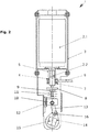
- the in the FIGS. 1 and 2 illustrated switch pole unit 1 has a vacuum switching chamber 2.1, which is arranged in a housing 3.
- a vacuum switching chamber 2.1 which is arranged in a housing 3.
- a first nut 4 which forms a lower contact surface for a Ausschaltfeder 5.
- the upper contact surface for the opening spring 5 forms the housing 3, so that the movable contact 2.2 with the opening spring 5 are in direct operative connection with each other.
- a flexible copper band 6 is connected to the movable contact 2.2, which is held on a cooperating with the nut 4 lower lock nut 7 on the movable contact 2.2.
- the copper band 6 and the movable contact 2.2 are electrically connected to each other and form the lower terminal point of the switch pole unit 1.
- the upper, with the fixed contact in the vacuum interrupter chamber connected terminal point of the switch pole unit is not
- the contact pressure device has a threaded adapter 8, which is firmly connected to the movable contact 2.2.
- the threaded adapter 8 is provided with an upper contact surface for a contact pressure spring 9, which is also part of the contact pressure device and is supported on its lower side on a piston-like drive element 10.
- At the bottom of the threaded adapter 8, it has a guide pin 11, whose longitudinal axis is aligned with that of the movable contact 2.2.
- the guide pin 11 is axially guided in a provided in the piston-like drive element 10 bushing 12 and freely movable in the axial direction. Since the drive element forms the lower bearing for the contact pressure spring 9, it is also considered as part of the contact pressure device.
- the piston-like drive element 10 is guided by a linear guide 12 in the axial direction of the movable contact.
- the linear guide is designed as a recirculating ball guide.
- the piston-like drive element is connected via a connecting rod 13 with the crank arm 14 of a crankshaft 15.
- the connecting rod is connected to the piston-like drive element 10 and the crank arm 14 via sliding or roller bearings.
- the crankshaft 15 is made of a non-conductive material.
- FIG. 2 shows the switch pole unit 1 in the on state.
- a connecting rod with the piston cheek 14 connecting crank pin 16 has almost reached its highest point in this state, so that of the Ausschaltfeder 5 while a moment acts on the crankshaft 16, but the moment is as low as possible.
- the drive should be locked by a suitable mechanism.
- the shutdown is carried out by releasing this Ausschaltverrastung (or a sustained drive torque), whereby the entire unit due to the biased Ausschaltfeder 5 back to the initial state, the in FIG. 1 is shown is offset.
- FIG. 3 shows a further embodiment, in which inertia and friction points are further reduced.
- the Ausschaltverrastung 20 which is usually located in the drive outside the Heidelbergerpoltician, directly integrated in the Heidelbergerpolech 1.
- the Ausschaltverrastung 20 is realized by a mounted in the housing 3 half-wave. After reaching the on position puts the crank arm 21 with a cam-like part 22 behind the half-wave, which faces the crank arm, and the on state is thus maintained.
- the half-wave Ausschaltverrastung 20 is released and the mechanism is returned to the initial state due to the force of the opening spring.
- the drive is designed so that the crankshaft 23 takes the connecting rod 13 only to behind the Ausschaltverrastung 20 and automatically returns from this position back to the starting point.
- the crankshaft 23 is rotatably mounted in the crank arm 21, wherein on the inner bearing surface of the crank arm 21, a franking 24 is provided, in which a provided on the crankshaft 23 shaft pin 25 engages, so that the free path for rotation of the crankshaft 23rd is limited relative to the crank arm 21.
Landscapes
- Driving Mechanisms And Operating Circuits Of Arc-Extinguishing High-Tension Switches (AREA)
- High-Tension Arc-Extinguishing Switches Without Spraying Means (AREA)
Claims (9)
- Unité polaire de commutateur, notamment pour un commutateur de puissance sous vide, comprenant une chambre de commutation sous vide (2.1) avec au moins un contact fixe et au moins un contact mobile (2.2), notamment une broche, qui peut être amené dans une position de marche ou de fermeture par l'intermédiaire d'un entraînement,
caractérisée par un guidage à circulation de billes agencé à distance de la chambre de commutation sous vide (2.1), pour assurer le guidage linéaire du contact mobile (2.2) ou d'un élément d'entraînement (10) qui y est relié et est déplacé linéairement dans la même direction. - Unité polaire de commutateur selon la revendication 1, caractérisée par un ressort d'arrêt ou d'ouverture (5), qui agit directement sur le contact mobile (2.2) ou sur un appui conjugué, qui y est fixé de manière rigide.
- Unité polaire de commutateur selon l'une des revendications 1 ou 2, caractérisée par un dispositif de pression de contact (8) agissant sur le contact mobile (2.2).
- Unité polaire de commutateur selon l'une des revendications 1 à 3, caractérisée en ce que l'entraînement présente un arbre à manivelle (15, 23) et une bielle (13) par laquelle un couple transmis par l'entraînement est converti en une force agissant axialement sur le contact mobile (2.2).
- Unité polaire de commutateur selon la revendication 4 rattachée à la revendication 3, caractérisée en ce que le point de rotation de la bielle (13) est agencé en-dessous du dispositif de pression de contact (8), sur l'axe longitudinal du contact mobile (2.2).
- Unité polaire de commutateur selon la revendication 4 ou la revendication 5, caractérisée en ce que la bielle (13) est reliée, par l'intermédiaire d'un système de palier lisse, à un élément du contact.
- Unité polaire de commutateur selon la revendication 4 ou la revendication 5, caractérisée en ce que la bielle (13) est reliée, par l'intermédiaire d'un système de palier à roulement, à un élément du contact.
- Unité polaire de commutateur selon les revendications 2 et 4 ou l'une des revendications 5 à 7, qui s'y rattachent, caractérisée par un encliquetage d'arrêt (20), qui peut agir sur une manivelle ou un flasque de manivelle (21) reliant la bielle (13) avec l'arbre à manivelle (23), en vue d'empêcher, dans l'état de marche ou de fermeture, une mise à l'arrêt directe en raison du ressort d'arrêt (5) précontraint.
- Unité polaire de commutateur selon la revendication 8, caractérisée en ce que l'arbre à manivelle (23) est monté rotatif dans le flasque de manivelle (21), en ce que dans une surface de palier intérieure du flasque de manivelle (21) est prévu un dégagement (24), et en ce que l'arbre à manivelle (23) présente un tenon d'arbre (25), qui s'engage dans le dégagement (24) et limite le parcours de déplacement libre pour la rotation de l'arbre à manivelle (23) par rapport au flasque de manivelle (21).
Applications Claiming Priority (1)
| Application Number | Priority Date | Filing Date | Title |
|---|---|---|---|
| DE202011106188U DE202011106188U1 (de) | 2011-09-30 | 2011-09-30 | Schalterpoleinheit |
Publications (3)
| Publication Number | Publication Date |
|---|---|
| EP2575153A2 EP2575153A2 (fr) | 2013-04-03 |
| EP2575153A3 EP2575153A3 (fr) | 2015-03-04 |
| EP2575153B1 true EP2575153B1 (fr) | 2017-07-19 |
Family
ID=46924312
Family Applications (1)
| Application Number | Title | Priority Date | Filing Date |
|---|---|---|---|
| EP12184683.6A Not-in-force EP2575153B1 (fr) | 2011-09-30 | 2012-09-17 | Unité de commutation de pôles |
Country Status (3)
| Country | Link |
|---|---|
| EP (1) | EP2575153B1 (fr) |
| DE (1) | DE202011106188U1 (fr) |
| DK (1) | DK2575153T3 (fr) |
Families Citing this family (3)
| Publication number | Priority date | Publication date | Assignee | Title |
|---|---|---|---|---|
| DE102014212583A1 (de) | 2014-06-30 | 2015-12-31 | Siemens Aktiengesellschaft | Vermeidung von Fehlausrichtungen einer Antriebsstange eines Leistungsschalters |
| FR3030103A1 (fr) * | 2014-12-11 | 2016-06-17 | Alstom Technology Ltd | Disjoncteur a moyens de guidage limitant les frottements internes |
| WO2018027545A1 (fr) * | 2016-08-09 | 2018-02-15 | 尚艳燕 | Véhicule à équilibrage électrique et ensemble pédale associé |
Citations (3)
| Publication number | Priority date | Publication date | Assignee | Title |
|---|---|---|---|---|
| JPS55131919A (en) * | 1979-03-30 | 1980-10-14 | Mitsubishi Electric Corp | Device for switching vacuum switch |
| DE2934776A1 (de) * | 1979-08-28 | 1981-03-12 | Siemens AG, 1000 Berlin und 8000 München | Mittelspannungslasttrennschalter. |
| DD240801A1 (de) * | 1985-09-06 | 1986-11-12 | Ilmenau Tech Hochschule | Schnellschalter |
Family Cites Families (13)
| Publication number | Priority date | Publication date | Assignee | Title |
|---|---|---|---|---|
| SE341491B (fr) * | 1969-05-09 | 1971-12-27 | Skf Svenska Kullagerfab Ab | |
| US3784774A (en) * | 1972-08-21 | 1974-01-08 | Ite Imperial Corp | Vacuum circuit breaker current transfer and actuation |
| DE2949753A1 (de) * | 1979-12-07 | 1981-06-11 | Siemens AG, 1000 Berlin und 8000 München | Hochspannungs-leistungsschalter |
| GB8819166D0 (en) * | 1988-08-12 | 1988-09-14 | Ass Elect Ind | Magnetic actuator & permanent magnet |
| FR2655768B1 (fr) * | 1989-12-13 | 1993-10-08 | Merlin Gerin | Interrupteur tripolaire a haute tension et a isolement gazeux. |
| DE4002934A1 (de) * | 1990-02-01 | 1991-08-08 | Sachsenwerk Ag | Vakuumschalter |
| DE4006452A1 (de) | 1990-03-01 | 1991-09-05 | Driescher Eltech Werk | Elektrischer schalter |
| DE19906156C2 (de) * | 1999-02-10 | 2001-12-13 | Siemens Ag | Vakuumschalter mit mindestens einer Vakuumschaltkammer |
| DE29906480U1 (de) | 1999-04-03 | 1999-09-09 | SGM Schaltgeräte Bad Muskau GmbH, 02953 Bad Muskau | Vakuum-Leistungsschalter |
| DE19959207C2 (de) * | 1999-12-08 | 2001-10-18 | Siemens Ag | Vakuumschütz mit verschiebbarem Führungselement |
| CN2590157Y (zh) * | 2002-12-10 | 2003-12-03 | 周鹤铭 | 高压隔离真空负荷开关联动操作机构 |
| CN201327799Y (zh) * | 2008-10-15 | 2009-10-14 | 镇江大全伊顿电器有限公司 | 断路器操纵机构脱扣装置 |
| CN201417684Y (zh) * | 2009-07-07 | 2010-03-03 | 涂大石 | 一种新型高压开关设备用电磁式操动机构 |
-
2011
- 2011-09-30 DE DE202011106188U patent/DE202011106188U1/de not_active Expired - Lifetime
-
2012
- 2012-09-17 DK DK12184683.6T patent/DK2575153T3/en active
- 2012-09-17 EP EP12184683.6A patent/EP2575153B1/fr not_active Not-in-force
Patent Citations (3)
| Publication number | Priority date | Publication date | Assignee | Title |
|---|---|---|---|---|
| JPS55131919A (en) * | 1979-03-30 | 1980-10-14 | Mitsubishi Electric Corp | Device for switching vacuum switch |
| DE2934776A1 (de) * | 1979-08-28 | 1981-03-12 | Siemens AG, 1000 Berlin und 8000 München | Mittelspannungslasttrennschalter. |
| DD240801A1 (de) * | 1985-09-06 | 1986-11-12 | Ilmenau Tech Hochschule | Schnellschalter |
Also Published As
| Publication number | Publication date |
|---|---|
| DE202011106188U1 (de) | 2013-01-09 |
| EP2575153A3 (fr) | 2015-03-04 |
| EP2575153A2 (fr) | 2013-04-03 |
| DK2575153T3 (en) | 2017-10-30 |
Similar Documents
| Publication | Publication Date | Title |
|---|---|---|
| DE102010015051B4 (de) | Mechanischer Schaltkontakt | |
| EP2843676B1 (fr) | Dispositif de commutation | |
| EP2815413B1 (fr) | Commutateur de prises en charge avec au moins deux vacuostats et actionnement pour un commutateur de prises en charge avec au moins deux vacuostats | |
| DE60130106T2 (de) | Unterbrecherschalter | |
| WO2016110430A1 (fr) | Élément de couplage pour commutateur électrique, en particulier tube commutateur à vide | |
| EP2575153B1 (fr) | Unité de commutation de pôles | |
| EP2337047B1 (fr) | Commutateur de puissance électrique ainsi qu'affichage de position correspondant | |
| EP1310970B1 (fr) | Disjoncteur hybride avec transmission | |
| DE102004060165B3 (de) | Schubtrennschalter | |
| DE7702053U1 (de) | Vakuumschaltgerät | |
| DE3906786C2 (fr) | ||
| EP1665304B1 (fr) | Dispositif permettant d'actionner un appareil de commutation electrique | |
| WO2004084241A2 (fr) | Commutateur de reglage en charge pour combinateur | |
| DE3943514C2 (fr) | ||
| WO2002041439A1 (fr) | Dispositif de contact pour disjoncteurs de protection limiteurs de courant | |
| EP1325508B1 (fr) | Unite d'arbre de commande pour commutateur electrique, notamment pour commutateur basse tension | |
| EP1334504B1 (fr) | Systeme de contact pour disjoncteurs limiteurs de courant | |
| EP4091186A1 (fr) | Unité de commande pour commander des contacts de commutation de disjoncteur haute tension | |
| DE3514184A1 (de) | Hochspannungsschalter mit einschaltwiderstand | |
| EP0197339A1 (fr) | Interrupteur à haute tension avec résistance de fermeture | |
| EP3011575B1 (fr) | Dispositif de transfert de forces | |
| EP0091082B1 (fr) | Appareil de commutation actionné électromagnétiquement | |
| DE19814398C1 (de) | Elektrisches Schaltgerät, insbesondere elektromagnetisches Schaltgerät mit Vakuumschaltröhre | |
| DE19813177C1 (de) | Elektrischer Schalter | |
| DE102019120185A1 (de) | Kopfgestaltung eines endschalters mit neutraler position mit teilereduktion und verbesserter zuverlässigkeit |
Legal Events
| Date | Code | Title | Description |
|---|---|---|---|
| PUAI | Public reference made under article 153(3) epc to a published international application that has entered the european phase |
Free format text: ORIGINAL CODE: 0009012 |
|
| AK | Designated contracting states |
Kind code of ref document: A2 Designated state(s): AL AT BE BG CH CY CZ DE DK EE ES FI FR GB GR HR HU IE IS IT LI LT LU LV MC MK MT NL NO PL PT RO RS SE SI SK SM TR |
|
| AX | Request for extension of the european patent |
Extension state: BA ME |
|
| RIC1 | Information provided on ipc code assigned before grant |
Ipc: H01H 3/46 20060101ALI20140728BHEP Ipc: H01H 33/666 20060101AFI20140728BHEP |
|
| PUAL | Search report despatched |
Free format text: ORIGINAL CODE: 0009013 |
|
| RIC1 | Information provided on ipc code assigned before grant |
Ipc: H01H 3/42 20060101ALI20150121BHEP Ipc: H01H 3/48 20060101ALN20150121BHEP Ipc: H01H 33/666 20060101AFI20150121BHEP |
|
| AK | Designated contracting states |
Kind code of ref document: A3 Designated state(s): AL AT BE BG CH CY CZ DE DK EE ES FI FR GB GR HR HU IE IS IT LI LT LU LV MC MK MT NL NO PL PT RO RS SE SI SK SM TR |
|
| AX | Request for extension of the european patent |
Extension state: BA ME |
|
| 17P | Request for examination filed |
Effective date: 20150904 |
|
| RBV | Designated contracting states (corrected) |
Designated state(s): AL AT BE BG CH CY CZ DE DK EE ES FI FR GB GR HR HU IE IS IT LI LT LU LV MC MK MT NL NO PL PT RO RS SE SI SK SM TR |
|
| 17Q | First examination report despatched |
Effective date: 20160927 |
|
| GRAP | Despatch of communication of intention to grant a patent |
Free format text: ORIGINAL CODE: EPIDOSNIGR1 |
|
| RIC1 | Information provided on ipc code assigned before grant |
Ipc: H01H 3/48 20060101ALN20170330BHEP Ipc: H01H 33/666 20060101AFI20170330BHEP Ipc: H01H 3/42 20060101ALI20170330BHEP |
|
| RIC1 | Information provided on ipc code assigned before grant |
Ipc: H01H 33/666 20060101AFI20170406BHEP Ipc: H01H 3/42 20060101ALI20170406BHEP Ipc: H01H 3/48 20060101ALN20170406BHEP |
|
| INTG | Intention to grant announced |
Effective date: 20170424 |
|
| RIN1 | Information on inventor provided before grant (corrected) |
Inventor name: BUENGER, STEFAN |
|
| GRAS | Grant fee paid |
Free format text: ORIGINAL CODE: EPIDOSNIGR3 |
|
| GRAA | (expected) grant |
Free format text: ORIGINAL CODE: 0009210 |
|
| AK | Designated contracting states |
Kind code of ref document: B1 Designated state(s): AL AT BE BG CH CY CZ DE DK EE ES FI FR GB GR HR HU IE IS IT LI LT LU LV MC MK MT NL NO PL PT RO RS SE SI SK SM TR |
|
| REG | Reference to a national code |
Ref country code: GB Ref legal event code: FG4D Free format text: NOT ENGLISH |
|
| REG | Reference to a national code |
Ref country code: CH Ref legal event code: EP |
|
| REG | Reference to a national code |
Ref country code: IE Ref legal event code: FG4D Free format text: LANGUAGE OF EP DOCUMENT: GERMAN |
|
| REG | Reference to a national code |
Ref country code: AT Ref legal event code: REF Ref document number: 911121 Country of ref document: AT Kind code of ref document: T Effective date: 20170815 |
|
| REG | Reference to a national code |
Ref country code: DE Ref legal event code: R096 Ref document number: 502012010790 Country of ref document: DE |
|
| REG | Reference to a national code |
Ref country code: NL Ref legal event code: FP |
|
| REG | Reference to a national code |
Ref country code: DK Ref legal event code: T3 Effective date: 20171023 |
|
| PGFP | Annual fee paid to national office [announced via postgrant information from national office to epo] |
Ref country code: CH Payment date: 20170915 Year of fee payment: 6 Ref country code: LU Payment date: 20170912 Year of fee payment: 6 |
|
| REG | Reference to a national code |
Ref country code: SE Ref legal event code: TRGR |
|
| PGFP | Annual fee paid to national office [announced via postgrant information from national office to epo] |
Ref country code: NL Payment date: 20170914 Year of fee payment: 6 Ref country code: DK Payment date: 20170918 Year of fee payment: 6 Ref country code: SE Payment date: 20170915 Year of fee payment: 6 Ref country code: AT Payment date: 20170914 Year of fee payment: 6 Ref country code: BE Payment date: 20170914 Year of fee payment: 6 |
|
| REG | Reference to a national code |
Ref country code: LT Ref legal event code: MG4D |
|
| REG | Reference to a national code |
Ref country code: NO Ref legal event code: T2 Effective date: 20170719 |
|
| PG25 | Lapsed in a contracting state [announced via postgrant information from national office to epo] |
Ref country code: FI Free format text: LAPSE BECAUSE OF FAILURE TO SUBMIT A TRANSLATION OF THE DESCRIPTION OR TO PAY THE FEE WITHIN THE PRESCRIBED TIME-LIMIT Effective date: 20170719 Ref country code: LT Free format text: LAPSE BECAUSE OF FAILURE TO SUBMIT A TRANSLATION OF THE DESCRIPTION OR TO PAY THE FEE WITHIN THE PRESCRIBED TIME-LIMIT Effective date: 20170719 Ref country code: HR Free format text: LAPSE BECAUSE OF FAILURE TO SUBMIT A TRANSLATION OF THE DESCRIPTION OR TO PAY THE FEE WITHIN THE PRESCRIBED TIME-LIMIT Effective date: 20170719 |
|
| PGFP | Annual fee paid to national office [announced via postgrant information from national office to epo] |
Ref country code: NO Payment date: 20170915 Year of fee payment: 6 |
|
| PG25 | Lapsed in a contracting state [announced via postgrant information from national office to epo] |
Ref country code: PL Free format text: LAPSE BECAUSE OF FAILURE TO SUBMIT A TRANSLATION OF THE DESCRIPTION OR TO PAY THE FEE WITHIN THE PRESCRIBED TIME-LIMIT Effective date: 20170719 Ref country code: ES Free format text: LAPSE BECAUSE OF FAILURE TO SUBMIT A TRANSLATION OF THE DESCRIPTION OR TO PAY THE FEE WITHIN THE PRESCRIBED TIME-LIMIT Effective date: 20170719 Ref country code: IS Free format text: LAPSE BECAUSE OF FAILURE TO SUBMIT A TRANSLATION OF THE DESCRIPTION OR TO PAY THE FEE WITHIN THE PRESCRIBED TIME-LIMIT Effective date: 20171119 Ref country code: BG Free format text: LAPSE BECAUSE OF FAILURE TO SUBMIT A TRANSLATION OF THE DESCRIPTION OR TO PAY THE FEE WITHIN THE PRESCRIBED TIME-LIMIT Effective date: 20171019 Ref country code: RS Free format text: LAPSE BECAUSE OF FAILURE TO SUBMIT A TRANSLATION OF THE DESCRIPTION OR TO PAY THE FEE WITHIN THE PRESCRIBED TIME-LIMIT Effective date: 20170719 Ref country code: GR Free format text: LAPSE BECAUSE OF FAILURE TO SUBMIT A TRANSLATION OF THE DESCRIPTION OR TO PAY THE FEE WITHIN THE PRESCRIBED TIME-LIMIT Effective date: 20171020 Ref country code: LV Free format text: LAPSE BECAUSE OF FAILURE TO SUBMIT A TRANSLATION OF THE DESCRIPTION OR TO PAY THE FEE WITHIN THE PRESCRIBED TIME-LIMIT Effective date: 20170719 |
|
| REG | Reference to a national code |
Ref country code: DE Ref legal event code: R097 Ref document number: 502012010790 Country of ref document: DE |
|
| PG25 | Lapsed in a contracting state [announced via postgrant information from national office to epo] |
Ref country code: CZ Free format text: LAPSE BECAUSE OF FAILURE TO SUBMIT A TRANSLATION OF THE DESCRIPTION OR TO PAY THE FEE WITHIN THE PRESCRIBED TIME-LIMIT Effective date: 20170719 Ref country code: RO Free format text: LAPSE BECAUSE OF FAILURE TO SUBMIT A TRANSLATION OF THE DESCRIPTION OR TO PAY THE FEE WITHIN THE PRESCRIBED TIME-LIMIT Effective date: 20170719 |
|
| PLBE | No opposition filed within time limit |
Free format text: ORIGINAL CODE: 0009261 |
|
| STAA | Information on the status of an ep patent application or granted ep patent |
Free format text: STATUS: NO OPPOSITION FILED WITHIN TIME LIMIT |
|
| PG25 | Lapsed in a contracting state [announced via postgrant information from national office to epo] |
Ref country code: IT Free format text: LAPSE BECAUSE OF FAILURE TO SUBMIT A TRANSLATION OF THE DESCRIPTION OR TO PAY THE FEE WITHIN THE PRESCRIBED TIME-LIMIT Effective date: 20170719 Ref country code: MC Free format text: LAPSE BECAUSE OF FAILURE TO SUBMIT A TRANSLATION OF THE DESCRIPTION OR TO PAY THE FEE WITHIN THE PRESCRIBED TIME-LIMIT Effective date: 20170719 Ref country code: SM Free format text: LAPSE BECAUSE OF FAILURE TO SUBMIT A TRANSLATION OF THE DESCRIPTION OR TO PAY THE FEE WITHIN THE PRESCRIBED TIME-LIMIT Effective date: 20170719 Ref country code: SK Free format text: LAPSE BECAUSE OF FAILURE TO SUBMIT A TRANSLATION OF THE DESCRIPTION OR TO PAY THE FEE WITHIN THE PRESCRIBED TIME-LIMIT Effective date: 20170719 Ref country code: EE Free format text: LAPSE BECAUSE OF FAILURE TO SUBMIT A TRANSLATION OF THE DESCRIPTION OR TO PAY THE FEE WITHIN THE PRESCRIBED TIME-LIMIT Effective date: 20170719 |
|
| 26N | No opposition filed |
Effective date: 20180420 |
|
| GBPC | Gb: european patent ceased through non-payment of renewal fee |
Effective date: 20171019 |
|
| REG | Reference to a national code |
Ref country code: IE Ref legal event code: MM4A |
|
| REG | Reference to a national code |
Ref country code: FR Ref legal event code: ST Effective date: 20180531 |
|
| PG25 | Lapsed in a contracting state [announced via postgrant information from national office to epo] |
Ref country code: IE Free format text: LAPSE BECAUSE OF NON-PAYMENT OF DUE FEES Effective date: 20170917 Ref country code: GB Free format text: LAPSE BECAUSE OF NON-PAYMENT OF DUE FEES Effective date: 20171019 |
|
| PG25 | Lapsed in a contracting state [announced via postgrant information from national office to epo] |
Ref country code: FR Free format text: LAPSE BECAUSE OF NON-PAYMENT OF DUE FEES Effective date: 20171002 Ref country code: SI Free format text: LAPSE BECAUSE OF FAILURE TO SUBMIT A TRANSLATION OF THE DESCRIPTION OR TO PAY THE FEE WITHIN THE PRESCRIBED TIME-LIMIT Effective date: 20170719 |
|
| PG25 | Lapsed in a contracting state [announced via postgrant information from national office to epo] |
Ref country code: MT Free format text: LAPSE BECAUSE OF FAILURE TO SUBMIT A TRANSLATION OF THE DESCRIPTION OR TO PAY THE FEE WITHIN THE PRESCRIBED TIME-LIMIT Effective date: 20170719 |
|
| REG | Reference to a national code |
Ref country code: NO Ref legal event code: MMEP |
|
| REG | Reference to a national code |
Ref country code: SE Ref legal event code: EUG Ref country code: CH Ref legal event code: PL |
|
| REG | Reference to a national code |
Ref country code: DK Ref legal event code: EBP Effective date: 20180930 |
|
| REG | Reference to a national code |
Ref country code: NL Ref legal event code: MM Effective date: 20181001 |
|
| REG | Reference to a national code |
Ref country code: AT Ref legal event code: MM01 Ref document number: 911121 Country of ref document: AT Kind code of ref document: T Effective date: 20180917 |
|
| PG25 | Lapsed in a contracting state [announced via postgrant information from national office to epo] |
Ref country code: SE Free format text: LAPSE BECAUSE OF NON-PAYMENT OF DUE FEES Effective date: 20180918 |
|
| REG | Reference to a national code |
Ref country code: BE Ref legal event code: MM Effective date: 20180930 |
|
| PG25 | Lapsed in a contracting state [announced via postgrant information from national office to epo] |
Ref country code: LU Free format text: LAPSE BECAUSE OF NON-PAYMENT OF DUE FEES Effective date: 20180917 Ref country code: NL Free format text: LAPSE BECAUSE OF NON-PAYMENT OF DUE FEES Effective date: 20181001 Ref country code: HU Free format text: LAPSE BECAUSE OF FAILURE TO SUBMIT A TRANSLATION OF THE DESCRIPTION OR TO PAY THE FEE WITHIN THE PRESCRIBED TIME-LIMIT; INVALID AB INITIO Effective date: 20120917 |
|
| PG25 | Lapsed in a contracting state [announced via postgrant information from national office to epo] |
Ref country code: NO Free format text: LAPSE BECAUSE OF NON-PAYMENT OF DUE FEES Effective date: 20180930 |
|
| PG25 | Lapsed in a contracting state [announced via postgrant information from national office to epo] |
Ref country code: BE Free format text: LAPSE BECAUSE OF NON-PAYMENT OF DUE FEES Effective date: 20180930 Ref country code: CH Free format text: LAPSE BECAUSE OF NON-PAYMENT OF DUE FEES Effective date: 20180930 Ref country code: LI Free format text: LAPSE BECAUSE OF NON-PAYMENT OF DUE FEES Effective date: 20180930 |
|
| PG25 | Lapsed in a contracting state [announced via postgrant information from national office to epo] |
Ref country code: DK Free format text: LAPSE BECAUSE OF NON-PAYMENT OF DUE FEES Effective date: 20180930 Ref country code: AT Free format text: LAPSE BECAUSE OF NON-PAYMENT OF DUE FEES Effective date: 20180917 Ref country code: CY Free format text: LAPSE BECAUSE OF NON-PAYMENT OF DUE FEES Effective date: 20170719 |
|
| PG25 | Lapsed in a contracting state [announced via postgrant information from national office to epo] |
Ref country code: MK Free format text: LAPSE BECAUSE OF FAILURE TO SUBMIT A TRANSLATION OF THE DESCRIPTION OR TO PAY THE FEE WITHIN THE PRESCRIBED TIME-LIMIT Effective date: 20170719 |
|
| PG25 | Lapsed in a contracting state [announced via postgrant information from national office to epo] |
Ref country code: TR Free format text: LAPSE BECAUSE OF FAILURE TO SUBMIT A TRANSLATION OF THE DESCRIPTION OR TO PAY THE FEE WITHIN THE PRESCRIBED TIME-LIMIT Effective date: 20170719 |
|
| PG25 | Lapsed in a contracting state [announced via postgrant information from national office to epo] |
Ref country code: PT Free format text: LAPSE BECAUSE OF FAILURE TO SUBMIT A TRANSLATION OF THE DESCRIPTION OR TO PAY THE FEE WITHIN THE PRESCRIBED TIME-LIMIT Effective date: 20170719 |
|
| PG25 | Lapsed in a contracting state [announced via postgrant information from national office to epo] |
Ref country code: AL Free format text: LAPSE BECAUSE OF FAILURE TO SUBMIT A TRANSLATION OF THE DESCRIPTION OR TO PAY THE FEE WITHIN THE PRESCRIBED TIME-LIMIT Effective date: 20170719 |
|
| PGFP | Annual fee paid to national office [announced via postgrant information from national office to epo] |
Ref country code: DE Payment date: 20210923 Year of fee payment: 10 |
|
| REG | Reference to a national code |
Ref country code: DE Ref legal event code: R119 Ref document number: 502012010790 Country of ref document: DE |
|
| PG25 | Lapsed in a contracting state [announced via postgrant information from national office to epo] |
Ref country code: DE Free format text: LAPSE BECAUSE OF NON-PAYMENT OF DUE FEES Effective date: 20230401 |